1
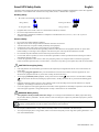
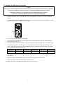
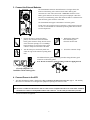
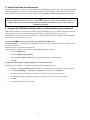
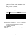
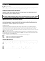
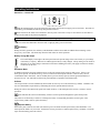
APC Smart-UPS Uninterruptible Power Supply Model 5000UXI User’s Manual 990-7082A REV4 7/01 Entire contents copyright © 2000 by American Power Conversion Corporation. All rights reserved. Reproduction in whole or in part without permission is prohibited. APC, Smart-UPS, and PowerChute are registered trademarks of American Power Conversion Corporation. All other trademarks are the property of their respective owners. 990-7082A REV4 7/01 Smart UPS Safety Guide English This Safety Guide contains important instructions that should be followed during installation and maintenance of the APC equipment and batteries. It is intended for APC customers who setup, install, relocate, or maintain APC equipment. Handling Safety •= •= •= •= Be careful. Do not lift heavy loads without assistance. = <18 kg (<40 lb.) = 32-55 kg (70-120 lb.) = 18-32 kg (40-70 lb.) = >55 kg (>120 lb.) Equipment with casters is built to move on a smooth surface without any obstacles. Do not use a ramp inclined at more than 10°. This equipment is intended for installation in a temperature-controlled indoor area (0 to 40ΓC (+32 to +104ΓF)), free of conductive contaminants. Electrical Safety •= •= •= •= •= •= •= •= Do not work alone under hazardous conditions. High short circuit current through conductive materials could cause severe burns. A licensed electrician is required to install permanently wired equipment. Check that the power cord(s), plug(s), and sockets are in good condition. To reduce the risk of electric shock when grounding cannot be verified, disconnect the equipment from the AC power outlet before installing or connecting to other equipment. Reconnect the power cord only after all connections are made. Do not handle any kind of metallic connector before the power has been removed. Use one hand, whenever possible, to connect or disconnect signal cables to avoid a possible shock from touching two surfaces with different electrical grounds. Connect the equipment to a three wire AC outlet (two poles plus ground). The receptacle must be connected to appropriate branch circuit/mains protection (fuse or circuit breaker). Connection to any other type of receptacle may result in a shock hazard. CAUTION! Deenergizing Safety •= •= •= •= •= If the equipment has an external battery pack connected, the output may be energized when the unit is not connected to an AC power outlet. To deenergize pluggable equipment: first press the Off button for more than one second to switch the equipment off. Next disconnect the equipment from the AC power outlet. Finally, disconnect the battery. To deenergize permanently wired equipment: set the power switch to standby . Next set the AC circuit breaker to standby . Then disconnect the batteries (including any expansion units). Finally, disconnect the AC power from the building power supply. Pluggable equipment includes a protective earth conductor which carries the leakage current from the load devices (computer equipment). Total leakage current must not exceed 3.5 mA. Use of this equipment in life support applications where failure of this equipment can reasonably be expected to cause the failure of the life support equipment or to significantly effect its safety or effectiveness is not recommended. WARNING! Battery Safety •= This equipment contains potentially hazardous voltages. Do not attempt to disassemble the unit. Battery replacement using the procedures below is permissible. The unit contains no user serviceable parts. Repairs are performed only by factory trained service personnel. Batteries must be recycled. Deliver the battery to an appropriate recycling facility or ship it to the supplier in the new battery’s packing material. See the new battery instructions for more information. •= •= •= Do not dispose of batteries in a fire. The batteries may explode. Do not open or mutilate batteries. They contain an electrolyte which is toxic and harmful to the skin and eyes. To avoid personal injury due to energy hazard, remove wrist watches and jewelry such as rings when replacing the batteries. Use tools with insulated handles.. 990-7082A REV4 7/01 Table of Contents Introduction....................................................................................................................................................................1 Unpacking......................................................................................................................................................................1 Installation .....................................................................................................................................................................1 Initial Startup .................................................................................................................................................................6 Operating Instructions....................................................................................................................................................7 User Configuration Items...............................................................................................................................................9 Storage ...........................................................................................................................................................................9 Battery Charge and Run Times ....................................................................................................................................10 Troubleshooting ...........................................................................................................................................................11 Service .........................................................................................................................................................................12 Limited Warranty.........................................................................................................................................................12 APC Contact Information ............................................................................................................................................12 iii 990-7082A REV4 7/01 Introduction About Your New UPS This Uninterruptible Power Supply (UPS) is designed to prevent blackouts, brownouts, sags and surges from reaching your computer and other valuable electronic equipment. This UPS also filters out small utility line fluctuations and isolates your equipment from large disturbances by internally disconnecting from the utility line, while supplying power from its external batteries until the utility line returns to safe levels. Unpacking Inspection Inspect the UPS upon receipt. Notify the carrier and dealer if there is damage. The packaging is recyclable; save it for reuse or dispose of it properly. Contents The shipping package contains the UPS, four IEC jumper cords, one C19 jumper cord, and a cable assembly to connect the battery. Caution: The 5000 VA model must be moved by a forklift due to its weight. Installation Installing your UPS requires six steps: 1. Position the UPS in the desired location.. 2. Hardwire the electrical connections on the input and output sides (must be done by an authorized electrician). 3. Connect the external batteries (UXBP48M or equivalent fused battery packs are recommended). 4. Power up the UPS. 5. 6. Install PowerChute UPS monitoring software and accessories. Program the UPS with the number of external battery packs connected. 1. Position the UPS Placement Install the UPS in a protected area that is free of excessive dust and has adequate air flow. Do not operate the UPS where the temperature and humidity are outside the specified limits. Warning! Changes or modifications to this unit not expressly approved by the party responsible for compliance could void the warranty. •= UPS are heavy. Select a location sturdy enough to handle the weight. •= Select a location with adequate air flow that is free from excessive dust. Ensure that any air vents on the sides of the UPS are not blocked. •= Do not operate the UPS where temperature is outside 0 to 40ΓC (+32 to +104ΓF) or humidity is outside.0 to 95%, non-condensing 1 2. Hardwire the Electrical Connection Caution: The electrical connection must be made by an authorized electrician according to national and local regulations. Verify that the supply line contains a 25 Ampere circuit breaker BEFORE hardwiring the UPS. Ensure that the batteries are not installed in the UPS until the hardwiring is complete. Incorporate a readily accessible disconnect device in the fixed wiring design. 1. Select the appropriate wire size and connectors. For most applications, #10 AWG (5 sq. mm) wire should be sufficient. 2. The input and output wiring terminals are located on the rear panel of the UPS. Remove the hardwire cover by unscrewing the single screw that holds it in place. 3. Use a screwdriver to loosen the Strain clamp . 4. Feed the input wire cable through the strain clamp on the left side and feed the output wire cable through the strain clamp on the right side. Use a knife or pliers to strip off the plastic on the end of the cable to expose the copper wire. Strip all six wires. 5. 6. Use a flathead screwdriver to connect the wires to the terminal block inside the UPS. Loosen the screw, then feed the copper wire into the terminal block and tighten the screw. Make sure the terminal block is wired from left to right as shown in the following table: Input Cable Input Cable Input Cable Output Cable Output Cable Output Cable Black (Hot) White (Neutral) Green (Ground) Green (Ground) Black (Hot) White (Neutral) 7. Once all the wires are connected to the terminal block, verify consistency of colors on the top and bottom of the terminal block. 8. Inspect the connections and location of the excess wires before tightening the strain clamp. 9. Using a screwdriver tighten the strain clamp securing the cables. 10. Replace the hardwire cover and fasten with the screw (removed in step 2). 2 3. Connect the External Batteries The SU5000UXI contains no internal batteries. The figure shows the location of the battery pack connector on the UPS. Battery pack connectors are color coded; the 48 Vdc UXBP48M connector is blue. Battery pack connectors are also keyed to prevent improper connection. Do not try to install battery packs with connectors that are a different color from the battery pack connector in the UPS. The SU5000UXI can support a maximum of 10 battery packs. If a DC bus is to be used for inverter operation, a voltage between 42 and 45 volts is recommended for continuous operation greater than two hours at room temperature. 1. Prepare the UPS to connect the battery pack(s). Note the holes used to attach the battery pack connector clamp (near the center of the connector opening). Use a #2 Phillips head screwdriver to remove the battery pack connector clamp from the back of the UPS. 3. 2. Turn the clamp over and loosely attach one end at the edge of the connector opening in the UPS. 4. Holding the clamp aside, insert the battery pack connector into the UPS. Secure the connector clamp. For additional battery packs, repeat this procedure using the battery pack connectors on the battery packs. Note: Do not stack battery packs. Stacking results in a tipping hazard. Correctly completed UXI installation with two battery packs. 4. Connect Power to the UPS •= The main SU5000UXI output is hardwired in Step 2. Hardwire the Electrical Connection, page 2. The auxiliary IEC and C19 connectors are not designed for equipment requiring more than 10A total. Caution: DO NOT use a standard serial interface cable to connect to the Computer Interface Port on the UPS. Standard serial interface cables are incompatible with the UPS connector. Use the cable provided with your UPS. •= Turn on all connected equipment. 3 5. Install PowerChute and Accessories For additional computer system security, install PowerChute UPS monitoring software. It provides automatic unattended shutdown capabilities on most major network operating systems. Once PowerChute is loaded, install the PowerChute® black communication cable between UPS and computer. See the Software Installation: Instruction Sheet for details. Notes: This UPS is equipped with one accessory slot. See the APC website (www.apc.com) for available accessories. If a standard accessory is installed in this UPS, follow the installation instructions for the accessory, which are included in the package. 6. Program the SU5000UXI with the number of external battery packs connected Smart-UPS UXI models are not designed to know how many external battery packs are connected to them. A customer must program the Smart-UPS UXI with the appropriate number of external batteries in one of four ways. It is important to follow these instructions. The number of batteries affects the runtime calculations which Smart-UPS performs when it is running on battery power. Use PowerChute® ® plus version 5.x for Windows 95, Windows 98, Windows NT. PowerChute® plus 5.x for Windows NT is compatible with NT 3.5.1 SP5, NT 4.0 Workstation (at least SP1), or NT 4.0 Server (at least SP1). Install the software per the instructions on the CD. After rebooting the computer, access the PowerChute® plus graphical user interface. 1. Click on Configuration. 2. Click on UPS Operating Parameters. 3. Adjust the External Battery Pack field to the appropriate number of external batteries. 4. Click OK. Use the Terminal Program to change the number of external battery packs Terminal is used in Windows 3.1x, Windows for Workgroups, and Windows NT 3.51. 1. EXIT out of the PowerChute® plus Server. In the case of Windows NT, the UPS Service must be stopped. 2. Go to: Program Manager > Accessories > Terminal. Double-click on the Terminal icon. 3. Select the COM port to which the black-colored interface cable is attached as the Connector. 4. The COM port settings are 2400 baud, 8 data bits, 1 stop bit, no parity, flow control is Xon/Xoff. 5. Click OK. 6. Continue with the steps in Table 1, page 5. 4 Use the HyperTerminal Program to change the number of external battery packs HyperTerminal is used for Windows 95, Windows 98, and Windows NT 4.0 1. EXIT out of the PowerChute® plus Server. In the case of Windows NT, the UPS service must be stopped. 2. From the Desktop, go to: Start => Programs => Accessories => HyperTerminal. Double-click on the HyperTerminal icon. 3. You are prompted to choose a name and select an icon. Give any name and then click OK. If a message appears which reads “...must install a modem,” disregard it and continue. 4. The port settings are 2400 baud, 8 data bits, 1 stop bit, no parity, flow control is Xon/Xoff. 5. Click on Advanced and ensure the box labeled FIFO buffer is NOT checked. 6. Click OK twice. 7. Once the terminal/hyperterminal window is open, follow the steps in Table 1. Table 1 Step # Type Produced Effect Step 1 Y Produces SM Step 2 > To see the number of external packs. (A new unit will display 000.) Step 3 + Adds a battery pack. Step 4 > To see the change in number of external battery packs. Step 5 - Subtracts a battery pack. Step 6 > To see the change in number of external battery packs. Use the Smart-UPS Battery Pack Utility (BATTPACK) This program can be used with DOS or at a Windows DOS prompt. BATTPACK cannot be used with a DOS emulator or VDM (virtual DOS machine) like those in Windows 95, Windows 98, or Windows NT. The APC UPS Link cable must be used to communicate to the UPS. There are two black cables which can be used; part numbers 940-0024C or 940-1524C. At the DOS prompt, type: battpack com[X] [Y] where: [X] represents the available serial port that Battery Pack Utility uses to access the Smart-UPS. [Y] represents the number of external battery packs. For example: C:> battpack com1 4 The black cable is attached to communication port 1. There are four external battery packs. The program confirms that the update is successful. 5 Initial Startup Charge the battery The UPS charges its battery whenever it is connected to utility power. The battery will charge fully during the first four hours of normal operation. Do not expect full runtime during this initial charge period. Connect Computer Interface Port (Optional) Power management software and interface kits can be used with this UPS. Use only kits supplied or approved by the manufacturer. If used, connect the interface cable to the 9-pin computer interface port on the back panel of the UPS. Secure the connector’s screws to complete the connection. Caution: DO NOT use a standard serial interface cable to connect to the Computer Interface Port on the UPS. Standard serial interface cables are incompatible with the UPS connector. Use the cable provided with your UPS. Connect Ground Leads to TVSS Connector (Optional) The UPS features a TVSS connector for connecting the ground lead on transient voltage surge-suppression (TVSS) devices such as telephone and network line protectors. The TVSS connector provides grounding through the UPS’s power cord ground conductor. To make a connection to the TVSS connector, loosen the screw and connect the surge suppression device’s ground lead. Tighten the screw to secure the lead. Voltage Sensitivity The UPS detects line voltage distortions such as spikes, notches, dips, and swells, as well as distortions caused by operation with inexpensive fuel-powered generators. By default, the UPS reacts to distortions by transferring to onbattery operation to protect the loads. Where power quality is poor, the UPS may frequently transfer to on-battery operation. If the loads can operate normally under such conditions, battery capacity and service life may be conserved by reducing the sensitivity of the UPS. To reduce UPS sensitivity, press the configuration button on the rear panel. Use a pointed object such as a pen to press the button. Press it once to set the UPS’s sensitivity to reduced. Press it again to set the sensitivity to low. Press the button a third time to reset normal sensitivity. normal reduced low When the UPS is set to normal sensitivity, the configuration LED is brightly lit. When it is set to reduced sensitivity, the LED is dimly lit. When it is set to low sensitivity, the LED is off. Low Battery Warning Interval By default, the low battery warning occurs when there are approximately two minutes of on-battery run time remaining. This may not be enough time to gracefully shut down some protected computer systems. To change the warning interval, press the rear panel configuration button while pressing and holding the front-panel on/test button. 2 min. When the LED is brightly lit, the low battery warning interval is approximately two minutes. 5 min. When the LED is dimly lit, the low battery warning interval is approximately five minutes. 7 min. When the LED is off, the low battery warning interval is approximately seven minutes. 6 Operating Instructions Switch On — Switch Off With the UPS plugged in, press and release the large upper on/test button to supply power to the loads. The loads are immediately powered while the UPS beeps and performs a self-test. Press and release the small, lower off button to turn off power to the loads. It may be convenient to use the UPS as a master on/off switch for the protected equipment. Note: Whenever the UPS is plugged in and utility voltage is present, the charger maintains battery charge. The on-line LED illuminates when the UPS is supplying utility power to the loads. On Battery During on-battery operation, the on-battery LED illuminates and the UPS sounds an audible alarm consisting of four beeps every 30 seconds. The alarm stops when the UPS returns to on-line operation. Battery Charge Bar Graph 100% 80% 60% 40% 20% The 5-LED display on the right of the front panel shows the present charge of the UPS’s battery as a percentage of the battery’s capacity. When all five LEDs light, the battery is fully charged. The top LED goes out whenever the battery is not 100% charged. When the lowest LED is flashing, the battery can supply less than two minutes of run time for the load. Shutdown Mode In shutdown mode the UPS stops supplying power to the load, waiting for the return of utility power. If there is no utility power present, external devices (e.g., servers) connected to the computer interface or the accessory slot can command the UPS to shut down. This is normally done to preserve battery capacity after the graceful shutdown of protected servers. The UPS will scroll the front panel indicators sequentially in shutdown mode. Self-test The UPS performs a self-test automatically when turned on, and every two weeks thereafter (by default). Automatic selftest eases maintenance requirements by eliminating the need for periodic manual self-tests. During the self-test, the UPS briefly operates the loads on-battery. If the UPS passes the self-test, it returns to on-line operation. If the UPS fails the self-test it immediately returns to on-line operation and lights the replace battery LED. The loads are not affected by a failed test. Recharge the battery overnight and perform the self-test again. If the replace battery LED is still on, replace the battery. Replace Battery If the battery fails a self-test, the UPS emits short beeps for one minute and the replace battery LED illuminates. The UPS repeats the alarm every five hours. Perform the self-test procedure to confirm replace battery conditions. The alarm stops when the battery passes the self-test. 7 Load Bar Graph 85% 67% 50% 33% 17% The 5-LED display on the left of the front panel represents the power drawn from the UPS as a percentage of total capacity. For example, if three LEDs are lit, the load is drawing between 50% and 67% of the UPS’s capacity. If all five LEDs light, thoroughly test your complete system to make sure that the UPS will not become overloaded. Overload When the UPS is overloaded (the connected loads exceed 5000 VA / 3750 W) , the overload LED comes on and the UPS emits a sustained tone. The alarm remains on until the overload is removed. Disconnect nonessential load equipment from the UPS to eliminate the overload. SmartTrim This LED comes on to indicate that the UPS is compensating for a high voltage. SmartBoost This LED comes on to indicate that the UPS is compensating for a low voltage. Low Battery When the UPS is operating on-battery and the energy reserve of the battery runs low, the UPS beeps continuously until the UPS shuts down from battery exhaustion or returns to on-line operation. Cold Start When the UPS is off and there is no utility power, use the cold start feature to apply power to the loads from the UPS’s battery. Note: Cold start is not a normal condition. •= Press and hold the on/test button until the UPS beeps. •=Release the on/test button during the beep and the loads are powered within four seconds. Note: The UPS starts a self-test as a part of this procedure. The self-test does not affect the voltage display. The utility voltage bar graph has a margin of error of ± 4%. 8 User Configuration Items Function Automatic Self-Test UPS ID Note: Setting these items requires optional software or hardware. Factory User Selectable Description Default Choices Every 14 Every 7 days (168 Sets the interval at which the UPS will days hours), On Startup execute a self-test. (336 hours) Only, No Self-Test UPS_IDEN Up to eight characters Use this field to uniquely identify the UPS to define the UPS. for network management purposes. Date of Last Battery Replacement Manufacture Date Date of Battery Replacement Reset this date on battery replacement. Minimum Capacity Before Return from Shutdown 0 percent 15, 50, 90 percent The UPS will charge its batteries to the specified percentage before return from a shutdown. Sensitivity Normal Reduced, Low Duration of Low Battery Warning 2 minutes 5, 7, 10 minutes Alarm Delay After Line Fail 5 second delay Shutdown Delay 20 seconds 30 second delay, At Low Battery Condition, No Alarm 180, 300, 600 seconds Set lower than normal sensitivity to avoid lowered battery capacity and service life in situations where the load can tolerate minor power disturbances. Sets the time before shutdown at which the UPS issues a low battery warning. Set higher than the default only if the OS needs the time for graceful shutdown. To avoid alarms for minor power glitches, set the alarm delay. Synchronized Turn-on Delay 0 seconds 60, 180, 300 seconds To avoid branch circuit overload, the UPS will wait the specified time after the return of utility power before turn-on. High Transfer Point 253 264, 271, 280 To avoid unnecessary battery usage, set the High Transfer Point higher if the utility voltage is chronically high and the load is known to work well under this condition. Low Transfer Point 196 188, 204, 208 Set the Low Transfer Point lower if the utility voltage is chronically low and the load can tolerate this condition. Sets the interval between when the UPS receives a shutdown command and when shutdown occurs. Storage Storage Conditions Store the UPS covered and upright in a cool, dry location, with its battery disconnected. 9 Battery Charge and Run Times Note: UPS battery life differs based on usage and environment. The tables below show both the time required for charging UPS and battery pack batteries for rated protection and typical run times. Note: The SU5000UXI is designed for use with the UXBP48M or equivalent 48 Volt battery pack. Typical Maximum Recharge Times (In Hours) To 90% Of Rated Capacity Number of Battery Packs Recharge Time Number of Battery Packs Recharge Time 1 5 6 18 2 8 7 20.5 3 10.5 8 23 4 13 9 25.5 5 15.5 10 28 SU5000UXI Typical On-battery Run Times Load VA With 1 battery pack With 2 battery packs With 3 battery packs With 4 battery packs With 5 battery packs With 6 battery packs 1000 4.3 9.0 14.5 20.0 25.0 30.0 2000 2.1 4.8 7.5 9.9 12.5 15.0 3000 1.2 2.4 3.6 4.8 6.0 7.2 4000 0.5 1.4 2.3 3.2 4.0 4.8 5000 0.3 0.8 1.4 2.0 2.5 3.0 10 Troubleshooting Use the chart below to solve minor UPS installation problems. Contact APC Technical Support Staff for assistance with complex UPS problems. See APC Contact Information page 12, for a location near you. Problem and Possible Cause UPS will not turn on. •=ON button not pushed. •=UPS not connected to AC power supply. •=UPS input circuit breaker tripped. •=Very low or no utility voltage. •=Battery not connected properly. UPS will not turn off. •=Internal UPS fault. Solution Press the ON button once to power the UPS and the load. Check that the power cable from the UPS to the power supply is securely connected at both ends. Reduce the load on the UPS by unplugging equipment and reset the circuit breaker (on back of UPS) by pressing the plunger back in. Check the AC power supply to the UPS with a table lamp. If very dim, have the utility voltage checked. Confirm the battery connections. Do not attempt to use the UPS. Unplug the UPS and have it serviced immediately. UPS operates on-battery although normal line voltage exists. Reduce the load on the UPS by unplugging equipment and •=UPS’s input circuit breaker tripped. reset the circuit breaker (on back of UPS) by pressing the plunger back in. Move the UPS to a different outlet on a different circuit. •=Very high, low, or distorted line voltage. Test the input voltage with the utility voltage display. If Inexpensive fuel powered generators can distort acceptable to the load, reduce the UPS’s sensitivity. Refer the voltage. to Voltage Sensitivity, page 6, for procedures. UPS beeps occasionally. None. The UPS is protecting the load. •=Normal UPS operation. UPS does not provide expected backup time. •=The UPS’s battery is weak due to recent outage or Charge the battery. Batteries require recharging after extended outages. Also, they wear faster when put into is near the end of its service life. service often or when operated at elevated temperatures. If the battery is near the end of its service life, consider replacing the battery even if the replace battery indicator is not yet lit. Check the UPS’s load display. Unplug less needed •=The UPS is overloaded. equipment, such as printers. Front panel indicators flash sequentially. None. The UPS will restart automatically when utility •=The UPS has been shut down by remote control. power returns. All indicators are lit and UPS emits a constant beeping. Do not attempt to use the UPS. Turn the UPS off and have •=Internal UPS fault. it serviced immediately. All indicators are off and UPS is plugged into wall outlet. None. The UPS will return to normal operation when the •=The UPS is shut down and the battery is power is restored and the battery has a sufficient charge. discharged from an extended outage. The replace battery light is lit. Do another self test to see if it clears. •=Weak batteries. Confirm the battery connections. •=Replacement batteries not connected properly. 11 Service If the UPS requires service do not return it to the dealer! Follow these steps: 1. Review the problems discussed in Troubleshooting, page 14, to eliminate common problems. 2. Verify that no circuit breakers are tripped. A tripped circuit breaker is the most common UPS problem! 3. If the problem persists, call Customer Service or visit the APC Internet Website (www.apc.com). 4. •= Note the model number of the UPS, the serial number, and the date purchased. A technician will ask you to describe the problem and try to solve it over the phone, if possible. If this is not possible the technician will issue a Returned Material Authorization Number (RMA#). •= If the UPS is under warranty, repairs are free. If not, there is a repair charge. Pack the UPS in its original packaging. If the original packing is not available, ask Customer Service about obtaining a new set. Note: Pack the UPS properly to avoid damage in transit. Never use Styrofoam beads for packaging. Damage sustained in transit is not covered under warranty. 5. Mark the RMA# on the outside of the package. 6. Return the UPS by insured, prepaid carrier to the address given to you by Customer Service. Limited Warranty American Power Conversion (APC) warrants its products to be free from defects in materials and workmanship for a period of two years from the date of purchase. Its obligation under this warranty is limited to repairing or replacing, at its own sole option, any such defective products. To obtain service under warranty you must obtain a Returned Material Authorization (RMA) number from customer support (see the Service section of the User’s Manual). Products must be returned with transportation charges prepaid and must be accompanied by a brief description of the problem encountered and proof of date and place of purchase. This warranty does not apply to equipment which has been damaged by accident, negligence, or misapplication or has been altered or modified in any way. This warranty applies only to the original purchaser who must have properly registered the product within 10 days of purchase. EXCEPT AS PROVIDED HEREIN, AMERICAN POWER CONVERSION MAKES NO WARRANTIES, EXPRESSED OR IMPLIED, INCLUDING WARRANTIES OF MERCHANTABILITY AND FITNESS FOR A PARTICULAR PURPOSE. Some states do not permit limitation or exclusion of implied warranties; therefore, the aforesaid limitation(s) or exclusion(s) may not apply to the purchaser. EXCEPT AS PROVIDED ABOVE, IN NO EVENT WILL APC BE LIABLE FOR DIRECT, INDIRECT, SPECIAL, INCIDENTAL, OR CONSEQUENTIAL DAMAGES ARISING OUT OF THE USE OF THIS PRODUCT, EVEN IF ADVISED OF THE POSSIBILITY OF SUCH DAMAGE. Specifically, APC is not liable for any costs, such as lost profits or revenue, loss of equipment, loss of use of equipment, loss of software, loss of data, costs of substitutes, claims by third parties, or otherwise. APC Contact Information Internet http://www.apc.com/support/contact 12