1
MT 2000TM, MTS 2000TM,
MTX 838TM, MTX 8000TM,
and MTX 9000TM
(MTSX)
Radio Service Software
User’s Guide
Software Part Number: RVN-4097
*6881074C50*
68P81074C50-J
Motorola
8000 West Sunrise Boulevard
Fort Lauderdale, Florida 33322
© 1996 by Motorola, Inc., Radio Products Group
8000 W. Sunrise Blvd., Ft. Lauderdale, FL 33322
Printed in U.S.A. 11/96. All Rights Reserved.
RSS Technical Support (Domestic): 800-367-4803 (Menu #5)
(International): 305-475-3778
68P81074C50-J
MT 2000TM, MTS 2000TM,
MTX 838TM, MTX 8000TM,
and MTX 9000TM
(MTSX)
Radio Service Software
User’s Guide
Software Part Number: RVN-4097L
TABLE OF CONTENTS
LIST OF FIGURES ......................................................................................................................................................................iv
LIST OF TABLES ........................................................................................................................................................................iv
SECTION 1. INTRODUCTION
1.1
1.2
1.3
INTRODUCING THE MT 2000, MTS 2000, MTX 838, MTX 8000, AND
MTX 9000 (MTSX) RADIO SERVICE SOFTWARE........................................................................................................1-1
PREREQUISITES ..........................................................................................................................................................1-2
USING THIS MANUAL ..................................................................................................................................................1-3
SECTION 2. GETTING STARTED AND INITIAL SETUP
2.1
2.2
2.3
2.4
2.5
2.6
2.7
2.8
2.9
ASSEMBLING THE HARDWARE .................................................................................................................................2-1
UNDERSTANDING COMPUTER BASICS ....................................................................................................................2-4
2.2.1
Identifying Major Computer Parts ....................................................................................................................2-6
2.2.1.1 Monitor...............................................................................................................................................2-6
2.2.1.2 System Unit .......................................................................................................................................2-6
2.2.1.3 Keyboard ...........................................................................................................................................2-6
UNDERSTANDING COMPUTER STORAGE SYSTEMS .............................................................................................2-7
2.3.1
Random Access Memory (RAM) .....................................................................................................................2-7
2.3.2
Read Only Memory (ROM) ..............................................................................................................................2-7
2.3.3
Hard-Disk Drive................................................................................................................................................2-7
2.3.4
Diskettes ..........................................................................................................................................................2-7
UNDERSTANDING THE DISK OPERATING SYSTEM (DOS) .....................................................................................2-8
WHAT'S ON THE RSS DISKETTES ...........................................................................................................................2-11
ORGANIZING YOUR HARD DISK AND DISKETTES.................................................................................................2-12
2.6.1
Organizing Your Hard Disk ............................................................................................................................2-13
2.6.2
Organizing Your Archive File Diskette ...........................................................................................................2-14
STARTING THE RSS ..................................................................................................................................................2-15
2.7.1
Making a Backup Copy of RSS Diskette(s) ...................................................................................................2-15
2.7.2
What To Do with Previous Versions of RSS Diskettes ..................................................................................2-16
2.7.3
Starting the RSS From the Hard Disk ............................................................................................................2-16
2.7.4
Installing the RSS on Your Hard Disk ............................................................................................................2-16
2.7.5
Installing the RSS on Multiple Computers or Networks .................................................................................2-17
2.7.6
Hard Disk RSS Startup Procedure.................................................................................................................2-17
2.7.7
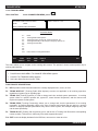
The Banner Screen........................................................................................................................................2-18
2.7.8
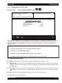
The Main Menu ..............................................................................................................................................2-19
NAVIGATING THROUGH THE RSS MENUS .............................................................................................................2-19
2.8.1
The Keyboard Keys and Their Functions.......................................................................................................2-20
2.8.2
Anatomy of a Menu........................................................................................................................................2-22
2.8.3
Anatomy of a Screen .....................................................................................................................................2-23
2.8.4
A Complete Menu Mapping at a Glance ........................................................................................................2-24
2.8.5
The Relationship Between Screens...............................................................................................................2-27
CHANGING A FIELD VALUE ......................................................................................................................................2-28
, Motorola, MT 2000, MTX 838, MTX 8000, MTX 9000, MTS 2000, Single Tone, SmartZone, HearClear,
Quik-Call, Quik-Call II,and Private-Line are trademarks of Motorola, Inc.
© 1993,1994,1996 by Motorola, Inc., Radio Products Group
8000 W. Sunrise Blvd., Ft. Lauderdale, FL 33322
Printed in U.S.A. 06/95. All Rights Reserved.
68P81074C50
i
TABLE OF CONTENTS (Cont.)
2.10
2.11
2.12
2.13
MTSX RSS
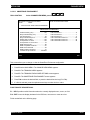
SETTING (CONFIGURING) THE RSS COMPUTER DEFAULTS ..............................................................................2-29
2.10.1 Setting Default Archive and Backup Paths ....................................................................................................2-30
2.10.2 Setting a Communications Port ....................................................................................................................2-31
EXITING THE RSS ......................................................................................................................................................2-32
MAIN MENU .................................................................................................................................................................2-33
2.12.1 How to Read the Codeplug............................................................................................................................2-35
2.12.1.1 Reading the Codeplug ...................................................................................................................................2-35
2.12.1.2 Reading Codeplug Data from the Radio ........................................................................................................2-35
2.12.1.3 Reading Disk Codeplug Files.........................................................................................................................2-35
SETUP CONFIGURATION ..........................................................................................................................................2-36
2.13.1 Configuring Paths and Port............................................................................................................................2-37
2.13.2 Setting Screen Colors ....................................................................................................................................2-39
SECTION 3. BASIC RADIO PROGRAMMING TUTORIAL
3.1
3.2
3.3
3.4
ii
INTRODUCTION TO SECTION.................................................................................................................3-1
PROGRAMMING A BASIC MT2000 CONVENTIONAL RADIO ................................................................3-2
3.2.1 Desired Features...........................................................................................................................3-2
3.2.2 Major Decisions Involved ..............................................................................................................3-2
3.2.3 High Level Programming Flow ......................................................................................................3-2
3.2.4 Step-by-Step Specific Programming Instructions..........................................................................3-2
3.2.5 MT2000 Button/Switch/Menu Item Defaults ..................................................................................3-4
3.2.6 Read Current Radio's Personality (Codeplug) ..............................................................................3-6
3.2.7 Program the Radio Wide Features First........................................................................................3-6
3.2.8 Program the Phone List.................................................................................................................3-7
3.2.9 Programming Conventional Personalties ......................................................................................3-7
3.2.10 Program the Zone/Channel Features Next ...................................................................................3-9
3.2.11 Fill in the Scan List ......................................................................................................................3-10
3.2.12 Program the Personality Into the Codeplug ................................................................................3-11
3.2.13 Program the Personality Into Archive and Backup Files .............................................................3-12
PROGRAMMING A BASIC MTX8000 TRUNKED RADIO.......................................................................3-13
3.3.1 Desired Features.........................................................................................................................3-13
3.3.2 Major Decisions Involved ............................................................................................................3-13
3.3.3 High Level Programming Flow ....................................................................................................3-13
3.3.4 Step-by-Step Specific Programming Instructions........................................................................3-13
3.3.5 MTX8000/9000 Radio Button/Switch/Menu Item Defaults ..........................................................3-15
3.3.6 Read Current Radio's Personality (Codeplug) ............................................................................3-17
3.3.7 TCMS Merge Process .................................................................................................................3-17
3.3.8 Program the Radio Wide Features First......................................................................................3-17
3.3.9 Steps to Assign Controls .............................................................................................................3-18
3.3.10 Program the Phone List...............................................................................................................3-20
3.3.11 Program a Talkgroup Scan with One List....................................................................................3-20
3.3.12 Steps to Modify Personalities ......................................................................................................3-21
3.3.13 Program the Zone/Channel Features Next .................................................................................3-22
3.3.14 Steps to Fill in the Scan List ........................................................................................................3-23
3.3.15 Program Data into Radio Codeplug ............................................................................................3-24
3.3.16 Exit the RSS ................................................................................................................................3-25
CLONING MORE RADIOS THE SAME WAY..........................................................................................3-25
3.4.1 Desired Features.........................................................................................................................3-25
3.4.2 Major Decisions Involved ............................................................................................................3-25
3.4.3 Step-by-Step Specific Programming Instructions........................................................................3-25
3.4.4 Read Desired Source Archive File ..............................................................................................3-26
3.4.5 Clone Current Radio From Archive File ......................................................................................3-26
3.4.6 Cloning Remaining Radios..........................................................................................................3-27
3.4.7 Cloning Additional Radios ...........................................................................................................3-28
68P81074C50
MTSX RSS
3.5
TABLE OF CONTENTS (cont.)
3.4.8 Exit the RSS ................................................................................................................................3-28
ADDITIONAL RADIO MODELS ...............................................................................................................3-29
3.5.1 MTS 2000 Radio Button/Switch/Menu Item Default ....................................................................3-30
SECTION 4. SERVICE MENU FUNCTIONS
4.1
4.2
RADIO SERVICE VIA RSS MANUAL ............................................................................................................................4-1
SERVICE MENU ............................................................................................................................................................4-1
4.2.1 Transmitter Alignment Menu ..............................................................................................................................4-3
4.2.1.1 Reference Oscillator Alignment...........................................................................................................4-5
4.2.1.2 Transmit Power Alignment ..................................................................................................................4-6
4.2.1.3 Transmit Deviation Balance (Compensation) Alignment.....................................................................4-8
4.2.1.4 Transmit Deviation Limit Alignment...................................................................................................4-10
4.2.1.5 Transmit Deviation Limit Alignment: Reference Softpot....................................................................4-11
4.2.1.6 Transmit VCO Crossover Alignment .................................................................................................4-12
4.2.1.7 Secure Transmit Deviation ................................................................................................................4-13
4.2.2 Receiver Alignment Menu ................................................................................................................................4-14
4.2.2.1 Front End Filter Alignment.................................................................................................................4-16
4.2.2.2. Rated Audio Alignment......................................................................................................................4-17
4.2.2.3 Squelch Attenuator (12.5kHz) Alignment ..........................................................................................4-18
4.2.2.4 Squelch Attenuator (20kHz) Alignment .............................................................................................4-19
4.2.2.5 Squelch Attenuator (25/30kHz) Alignment ........................................................................................4-20
4.2.2.6 Receive VCO Crossover Alignment ..................................................................................................4-21
4.2.2.7 Secure Receive Discriminator Level .................................................................................................4-22
4.2.3 Signalling Alignment Menu ..............................................................................................................................4-23
4.2.3.1 DTMF Transmit Deviation .................................................................................................................4-24
4.2.3.2 Transmit Signalling: High Speed .......................................................................................................4-26
4.2.3.3 Transmit Signalling: MDC 1200.........................................................................................................4-27
SECTION 5. GET/SAVE/PROGRAM MENU FUNCTIONS
5.1
5.2
INTRODUCTION TO SECTION.....................................................................................................................................5-1
GET/SAVE/PROGRAM MENU ......................................................................................................................................5-1
5.2.1 Reading Codeplug Data.....................................................................................................................................5-3
5.2.1.1 Reading Codeplug Data From the Radio ............................................................................................5-3
5.2.1.2 Reading Codeplug Data From an Archive File....................................................................................5-4
5.2.2 Get TCMS Ccodeplug update disk file ..............................................................................................................5-6
6.2.2 Radio Cloning
...........................................................................................................................................5-7
5.2.4 Saving Codeplug data to an archive file ..........................................................................................................5-10
5.2.5 Programming the Radio’s Codeplug ................................................................................................................5-12
5.2.6 Programming History .......................................................................................................................................5-13
SECTION 6. CHANGE/VIEW MENU FUNCTIONS
6.1
6.2
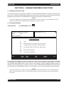
INTRODUCTION TO SECTION.....................................................................................................................................6-1
CHANGE VIEW MENU ..................................................................................................................................................6-1
6.2.1 Radio Wide Configuration Menu ........................................................................................................................6-3
6.2.1.1. Radio Wide Options ............................................................................................................................6-4
6.2.1.1.1 Radio Wide Secure Options ..............................................................................................6-8
6.2.1.1.2 Radio Wide Emergency Options......................................................................................6-10
6.2.1.1.3 More Radio Wide Options................................................................................................6-12
6.2.1.2 Radio Wide Features Configuration Menu ........................................................................................6-14
6.2.1.2.1 Radio Wide Button Configuration ....................................................................................6-15
6.2.1.2.2 Radio Wide Switch Configuration ....................................................................................6-18
6.2.1.2.3 Radio Wide Menu Item Configuration..............................................................................6-20
6.2.1.3 Phone Configuration..........................................................................................................................6-23
6.2.1.3.1 DTMF Access/Deaccess Codes ......................................................................................6-25
6.2.1.3.2 Dial Options ....................................................................................................................6-27
68P81074C50
iii
MTSX RSS
TABLE OF CONTENTS (cont.)
6.2.1.4
6.2.2
6.2.3
6.2.4
Radio Wide Scan Lists And Options .................................................................................................6-29
6.2.1.4.1 Radio Wide Scan Options................................................................................................6-32
6.2.1.5 Radio Wide Display Options..............................................................................................................6-35
6.2.2.5.1 Radio Wide Display More Options...................................................................................6-38
Trunking Menu .................................................................................................................................................6-40
6.2.2.1 Trunking Radio Wide Options ...........................................................................................................6-40
6.2.2.1.1 SmartZone Environment..................................................................................................6-42
6.2.2.1.2 Voice on Control Options.................................................................................................6-46
6.2.2.2 Trunking Systems..............................................................................................................................6-48
6.2.2.2.1 Channel Assignment Data ...............................................................................................6-54
6.2.2.2.2 Control Channel ..............................................................................................................6-56
6.2.2.3 Trunking System Options.................................................................................................................6-58
6.2.2.3.1 One Touch Button Options.................................................................................................6-61
6.2.2.3.2.Trunking Status Alias .........................................................................................................6-62
6.2.2.2.3 Trunking Message Alias .....................................................................................................6-63
6.2.2.4 Trunking Personality ......................................................................................................................6-64
6.2.2.4.1 Trunking Subfleets...........................................................................................................6-70
6.2.2.4.2 Trunking Talkgroup..........................................................................................................6-71
6.2.2.4.3 Trunking Emergency Data Configuration.........................................................................6-73
6.2.2.4.4 Trunking Personality Options...........................................................................................6-77
6.2.2.4.4.1 SmartZone Preferred Sites ...........................................................................6-79
6.2.2.5 Trunking Call List...............................................................................................................................6-81
Conventional Menu ..........................................................................................................................................6-82
6.2.3.1 Conventional Radio Wide Options ....................................................................................................6-85
6.2.3.2 Conventional Personality Using GE Star Signalling ..........................................................................6-87
6.2.3.2.1 Personality MDC Options ................................................................................................6-93
6.2.3.2.2 Conventional Personality Phone Options ........................................................................6-96
6.2.3.2.3 More Conventional Personality Options ..........................................................................6-98
6.2.3.2.3.1 Conventional RAC Options.........................................................................6-102
6.2.3.3 MDC Configuration Menu................................................................................................................6-104
6.2.3.3.1 MDC Systems ...............................................................................................................6-105
6.2.3.3.2 More Emergency Options .............................................................................................6-109
6.2.3.3.2.1 MDC System Options .................................................................................6-110
6.2.3.3.2.2 MDC System Remote Options....................................................................6-113
6.2.3.3.3 Call List Table.................................................................................................................6-115
6.2.3.4 Auxaliry Systems.............................................................................................................................6-117
6.2.3.4.1 Singletone System.........................................................................................................6-119
6.2.3.4.2 Singletone List ...............................................................................................................6-121
6.2.3.4.3 Quik-Call II System ........................................................................................................6-122
6.2.3.4.4 GE Star System .............................................................................................................6-125
6.2.3.4.5 Conventional Message Alias List...................................................................................6-128
6.2.3.4.6 Conventional Status Alias List .......................................................................................6-130
Zone/TalkGroup (Channel) Assignment ........................................................................................................6-132
SECTION 7. PRINT MENU FUNCTIONS
7.1
INTRODUCTION TO SECTION ....................................................................................................................................7-1
7.1.1
Print Radio Wide Features Configuration Menu ..............................................................................................7-3
7.1.2
Trunking Menu .................................................................................................................................................7-4
7.1.3
Conventional Menu ..........................................................................................................................................7-5
SECTION 8. FILE MAINTENANCE MENU FUNCTIONS
8.1
8.2
iv
INTRODUCTION TO SECTION ....................................................................................................................................8-1
FILE MAINTENANCE MENU.........................................................................................................................................8-1
8.2.1
Create Directory Path ......................................................................................................................................8-3
8.2.2
Delete Archive File...........................................................................................................................................8-4
68P81074C50
MTSX RSS
TABLE OF CONTENTS (cont.)
SECTION 9. FLASHPORT UPGRADE
9.1
9.2
9.3
INTRODUCTION TO FLASHPORT ...............................................................................................................................9-1
FLASHING PROCEDURE .............................................................................................................................................9-1
FLASHING UPGRADE ..................................................................................................................................................9-2
APPENDIX A Computer to Radio Communications Error Codes .........................................................................A-1
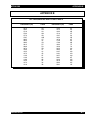
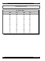
APPENDIX B TPL Frequencies and Codes Table...............................................................................................B-1
APPENDIX C MTSX Features ..............................................................................................................................C-1
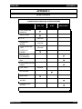
APPENDIX D Trunking Radio Personality Chart ..................................................................................................D-1
APPENDIX E Conventional Radio Personality Chart............................................................................................E-1
KEY MENU INDEX.......................................................................................................................................INDEX-1
GLOSSARY ..........................................................................................................................................................G-1
v
68P81074C50
TABLE OF CONTENTS (cont.)
MTSX RSS
LIST OF TABLES
1-1
2-1
2-2
2-3
2-4
2-5
2-6
2-7
2-8
2-9
2-10
2-11
3-1
3-2
3-3
3-4
3-5
3-6
3-7
3-8
3-9
3-10
3-11
3-12
3-13
3-14
3-15
3-16
3-17
3-18
3-19
3-20
3-21
3-22
3-23
3-24
3-25
3-26
3-27
3-28
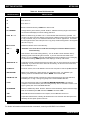
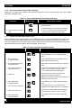
Types of RSS Programmable Features and Functions ............................................................................1-1
Step to Connect Hardware........................................................................................................................2-3
Installation Tone Identification ..................................................................................................................2-3
Some DOS Commands ............................................................................................................................2-9
Special DOS Command Characters .......................................................................................................2-10
RSS Diskette(s) Contents .......................................................................................................................2-11
Steps to Create a Hard Disk Directory Tree ...........................................................................................2-15
Steps to Backup the RSS Diskette(s) .....................................................................................................2-16
RSS Hard Disk Installation Procedure ....................................................................................................2-18
Hard Disk Startup Procedures ................................................................................................................2-19
Creating Archive File Paths ....................................................................................................................2-32
Setting a Port ..........................................................................................................................................2-33
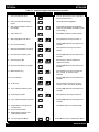
Quick Steps to Bring Up MAIN MENU ......................................................................................................3-1
Conventional Radio Personality Chart ......................................................................................................3-3
MT2000 Radio Button / Switch / Menu Item Defaults ...............................................................................3-4
Steps to Read A Radio's Personality (Codeplug) .....................................................................................3-6
Steps to Program Radio-Wide Features ...................................................................................................3-6
Steps to Create a Phone List ....................................................................................................................3-7
Steps to Program Conventional Personalties ...........................................................................................3-8
Steps to Program Zone/Channel Features ...............................................................................................3-9
Steps to Create a Scan List ....................................................................................................................3-10
Steps to Save Personality to Radio's Codeplug......................................................................................3-11
Steps to Save Radio Personality to Archive and Backup Files...............................................................3-12
Trunked Radio Personality Chart............................................................................................................3-14
MTX8000/9000 Radio Button / Switch / Menu Item Defaults..................................................................3-15
Steps to Read a Radio's Personality (Codeplug)....................................................................................3-17
Steps to Merge/Download TCMS ...........................................................................................................3-17
Steps to Assign Button and Switch Functions ........................................................................................3-18
Steps to Program the Phone List ............................................................................................................3-19
Steps to Program Talkgroup Scan with One Lis .....................................................................................3-20
Steps to Modify Personalities for Scan and Phone.................................................................................3-21
Steps to Program Zone/Channel Features .............................................................................................3-22
Steps to Fill in the Scan List....................................................................................................................3-23
Steps to Save Personality to Radio's Codeplug......................................................................................3-24
Steps to Exit the RSS .............................................................................................................................3-25
Steps to Clone Radios ............................................................................................................................3-27
Cloning Additional Radios.......................................................................................................................3-28
Steps to Exit the RSS .............................................................................................................................3-28
MTS2000 Radio Button/Switch/Menu Item Defaults...............................................................................3-29
MTS2000 Radio Button/Switch/Menu Item Defaults...............................................................................3-30
68P81074C50
vi
MTSX RSS
TABLE OF CONTENTS (cont.)
LIST OF FIGURES
2-1
2-2
2-3
2-4
2-5
2-6
2-7
2-8
2-9
2-10
2-11
2-12
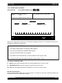
Equipment Setup ....................................................................................................................................................2-1
Hard Disk Directory Tree ......................................................................................................................................2-13
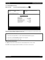
Diskette Directory Tree .........................................................................................................................................2-14
The Banner Screen...............................................................................................................................................2-20
The Main Menu .....................................................................................................................................................2-21
The Computer Keyboard ......................................................................................................................................2-21
An RSS Menu .......................................................................................................................................................2-24
An RSS Screen.....................................................................................................................................................2-25
RSS Menu Mapping at a Glance ..........................................................................................................................2-27
Relationship Between Screens.............................................................................................................................2-29
Changing a Field Value ........................................................................................................................................2-30
Service Software Configuration Menu Options.....................................................................................................2-31
3-1
3-2
Button Locator Diagram (Button Location Purposes Only).....................................................................................3-5
Button Locator Diagram (Button Location Purposes Only)...................................................................................3-16
vii
68P81074C50
MTSX RSS
NOTES
viii
68P81074C50
MTSX RSS
INTRODUCTION
SECTION 1. INTRODUCTION
Welcome to the world of two-way radio programming from Motorola's Radio Products Group.
1.1 INTRODUCING THE MT 2000™, MTS 2000™, MTX 838™, MTX 8000™, AND MTX 9000™ (MTSX)
RADIO SERVICE SOFTWARE
This Radio Service Software (RSS) manual is targeted for anyone who wants to program features into the
MT 2000, MTS 2000, MTX 838, MTX 8000, and MTX 9000 radios or align a radio. This feature programming, or
customizing, personalizes a radio for the needs of individual customers, resulting in radios with unique
personalities.
This series of portable radios has a unique set of features, including unique PL/DPL codes for each channel, a
variety of signalling abilities with channel scan, and the convenience of maintenance-free tuning, due to the
wideband capability.
This feature set makes these radios ideal for commercial businesses and police and fire protection services that
typically utilize radios in their vehicles.
So how can Motorola design radios with such a wide range of features and still offer a variety of radio services
with the ability to customize and personalize radios? The answer is embedded in modern microprocessor chip
technology in the radio and the development of the MTSX RSS - a computer program that, when interfaced with a
radio, electronically programs and personalizes a radio with a unique set of features for each individual customer.
No tools are needed. This RSS computer program resides on the diskettes you received in the package with this
manual (package RVN4097I).
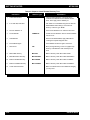
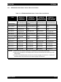
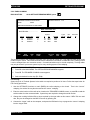
Here are just some of the features and functions available using the RSS.
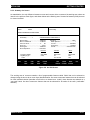
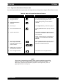
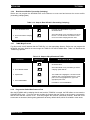
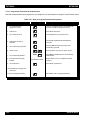
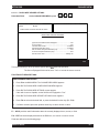
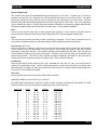
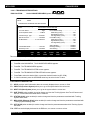
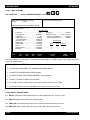
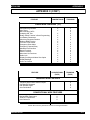
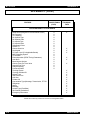
Table 1-1. Types of RSS Programmable Features and Functions
MTSX RSS Programmable Features
MTSX RSS Service Functions
Transmit (Tx) frequencies
Reference oscillator alignment
Receive (Rx) frequencies
Transmit deviation alignment
PL/DPL codes
Transmit power alignment
Signalling system parameters
Replaced power amplifier calibration
Scan lists and scan options
Replaced logic board calibration
FLASHport Upgrade (requires FLASHport
Replaced RF board calibration
upgrade package)
This radio’s customization and servicing is accomplished by using an IBM® Personal System/2® model 30 or
higher computer.
NOTE
We recommend you test any computer’s RSS compatibility before purchasing by taking the computer to your shop,
connecting all the hardware, installing the software, starting the RSS and reading and writing data to and from a
radio. If problems occur, call the phone number on the front cover for help - do this prior to purchasing your
computer.
68P81074C50
1-1
INTRODUCTION
MTSX RSS
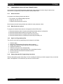
1.2 PREREQUISITES
To use the RSS to program the radios, we recommend a basic working knowledge of the following:
1.
Microcomputers.
2.
MS-DOS operating system, version 5.0 or later.
This application requires:
80386 or 80486
DOS 5.0 or later
4 Megabytes of RAM or greater.
The powerful features and extensive flexibility of these new radio families require much more codeplug data
validation than in the past. For complex configurations, it is recommended that the RSS be executed from a RAM
disk. This will reduce execution time significantly (an order of magnitude).
3.
The radio’s available features (see the appropriate radio Operator's Manual).
4.
Your customers’ needs.
For computer beginners, we’ll teach some computer and MS-DOS basics. However, this manual is written for
both beginners and advanced users, so the primary prerequisite for using the RSS is the desire to program and
deliver an excellent radio to a ready customer.
1.3
INTRODUCTION OF NEW RELEASE
This release of the MTSX RSS utilizes the extended memory capability of the 386 and 486 PCs. To take
advantage of these performance enhancements your machine must be a 386 or 486 based machine with 4M of
memory (1M lower + 3M or more extended). This application is compatible with DOS 6.0, but cannot be run as a
Double Space file.
With extended memory, the application will now run with less than 100K of conventional memory available!
Resident programs and TSR (Terminate & Stay Resident) utilities no longer have to be disabled. This has also
permitted the installation procedure to be significantly improved and simplified. The CONFIG.SYS modifications
required to run the application have been automated, and are described in the rest of this introduction.
A new Tutorial section (Chapter 3) has been added to the manual to discuss programming requirements of some
of the specific MT2000, MTX8000, MTX9000, and MTS2000 models. This release added support for Secure
MTS2000 radio models, and also corrected some defects of the previous release.
1.3.1 EXTENDED MEMORY OPERATION
Previous versions of this application recommended the usage of extended memory for a RAMDrive to reduce the
disk I/O access time. (The application however, only used conventional memory for actual execution.) This
version does not require the use of a RAMDrive or a SMARTDrive.
1-2
68P81074C50
MTSX RSS
INTRODUCTION
The new install program will determine if your system has an adequate amount of memory available (3M) and a
286, 386 (or 486) CPU for extended memory operation. If present, the RSS will be installed.
The following line should be added to the CONFIG.SYS file if necessary:
device = c:\dos\HIMEM.SYS
device =c: \dos\EMM386.EXE OFF
Files = 30
NOTE
The DOS MEM command may be used to determine the amount of available
memory in your machine (i.e. type c:\dos\mem. The location of MEM.EXE may
differ on your machine.) If the command reports 3000K or more of available
extended memory, you can take full advantage of these enhancements.
1.4 SUBSCRIPTION INFORMATION
Your RSS is part of a subscription. We’ll keep you advised of changes and automatically mail revisions
throughout the life of the subscription.
A subscription is good for one site. Under the terms of your subscription, you may install the RSS on as many
personal computers as desired at that one site. Another site location requires another subscription.
1.5 USING THIS MANUAL
This manual is designed to teach basic feature programming and to speed up access to technical reference
information. It is intended for both beginners and advanced users of computers and the RSS. This manual
describes how to connect the radio to your computer and how to install the software. The operation of the
software is described, including how to read the screens, the keyboard commands, and how the screens are
organized.
The MAIN MENU and all available RSS functions are described in detail. The operation of the SERVICE
functions, the GETTING and SAVING of radio codeplug data, and the CHANGING and VIEWING of codeplug
data are described also.
All RSS function screens are depicted in this manual and the operation of each one is described. A description of
each data field is also given.
The GLOSSARY defines terms and abbreviations used within this manual.
The INDEX provides a quick way of locating particular items.
NOTES, CAUTIONS, and WARNINGS are used throughout this manual. The following definitions apply to the
these statements,
NOTE
An operating procedure or condition which is essential to highlight.
CAUTION
An operating procedure or practice which, if not strictly observed, might result in damage or
destruction of equipment.
WARNING
AN OPERATING PROCEDURE OR PRACTICE WHICH MIGHT RESULT IN PERSONAL INJURY OR
LOSS OF LIFE IF NOT CORRECTLY FOLLOWED.
68P81074C50
1-3
INTRODUCTION
MTSX RSS
NOTES
1-4
68P81074C50
MTSX RSS
GETTING STARTED
SECTION 2. GETTING STARTED AND INITIAL SETUP
Introductions accomplished, it’s time to get started. In the GETTING STARTED subsection we’ll guide you
through identifying, installing and learning the necessary hardware and software to run the RSS, which will be
used to service and program a radio. In the GETTING STARTED subsection, we’ll also familiarize you with the
computer, the keyboard, and the RSS menus, screens, and fields. The INITIAL SETUP subsection prepares you
for SECTION 2 through SECTION 8, which describe how to service and program a radio, and maintain your radio
service files.
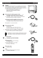
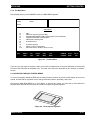
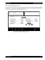
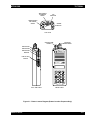
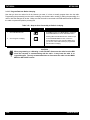
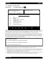
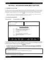
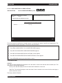
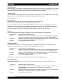
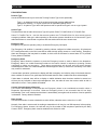
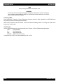
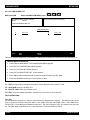
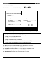
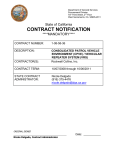
2.1 ASSEMBLING THE HARDWARE
The figure below shows the required and optional equipment to program a radio. The computer recommended is
an IBM® Personal System/2® model 30 or higher computer, with 640K of RAM, one diskette drive, and one hard
disk drive.
D
F
A
B
C
E
MAEPF-22704-O
Figure 2-1. Equipment Setup
68P81074C50
2-1
GETTING STARTED
A
B
MTSX RSS
Computer
An IBM® Personal Computer XTTM (or compatible) may be used, but
we recommend as a minimum a 386 based computer is required to
improve throughput (a 80386 based computer or higher is preferred),
or IBM® Personal System/2® (model 30 or higher)
Computer should have 640k of RAM, one
diskette drive, and one hard drive; computer
should run DOS 5.0.
Radio Interface Box (RIB) to Computer Cable
30-80369B72 cable for IBM® Personal Computer AT®
or compatible computer (9-pin end and a 15-pin end)
or 30-80369B71 cable for computers requiring a 25-pin serial
port connection (25-pin end and a 15-pin end)
Smart Radio Interface Box (SRIB) to Computer Cable
30-80390B49 cable for IBM® Personal Computer AT®
or compatible computer (9-pin end and a 15-pin end)
See Appendix A for connection details.
C
Radio Interface Box (RIB)
RLN4008B RIB
For laptop computer and on-the-road use only;
omit item D below and use a 9V battery (not included).
or
Smart Radio Interface Box (SRIB) for FLASHport Only
RLN1015A RIB (required for FLASHport upgrade)
CAUTION: Use a fresh, 9V battery. LED remains lit with a
weak battery - this may cause certain errors on screen.
D
RIB Power Supply
01-80357A57 (110 Vac) Power Supply
or 01-80358A56 (220 Vac) Power Supply
SRIB Power Supply
01-80302E27 (120 Vac) Power Supply
For FLASHport Only
Using the power supply is more reliable
than using a weak battery.
E
RIB-to-Radio Cable
RKN4035A Cable
F
Radio
MT 2000, MTS 2000, MTX 838, MTX 8000
or MTX 9000 Portable Radio.
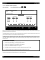
MT 2000
1
2 AB C
3DEF
4 GHI
5 JKL
6 MNO
7P R S
8 TUV
9WXY
0
HOME
2-2
68P81074C50
MTSX RSS
GETTING STARTED
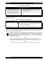
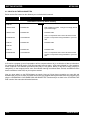
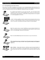
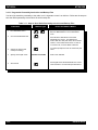
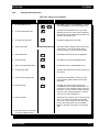
Table 2-1. Steps to Connect Hardware
Steps to Connect the Hardware
1. Connect A and C with B. First, plug the
9-pin end of B into the communications port
of A. Then connect the 15-pin end to C.
If your computer has a 25-pin connections
port connector, you will need the cable 3080369B71 to insert between A and B.
2. Connect F and C with E. The 25-pin end of E goes into C,
and the modular telephone connector end plugs into the side
connector on the front of F.
3. Plug D into the wall outlet, and connect the other end to C.
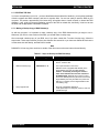
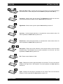
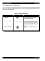
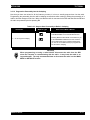
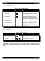
After you connect the hardware, turn on the radio by turning the volume control clockwise. You will hear one of
the following types of tones.
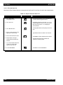
Table 2-2. Installation Tone Identification
This tone .....
Means this....
Higher-pitched, short tone
Hardware is connected correctly and the radio's internal firmware
is operating correctly. Note: This tone may be disabled in the
codeplug and may not be heard.
Continuous, low tone
Critical failure - a radio's internal software malfunction.
You can install, start or explore the RSS using just the diskettes and your computer if you don’t have all the
hardware. You can even update existing radio archive files stored on disk. What you cannot do without the
hardware is read from or save to an actual radio.
CAUTION: When programming or calibrating a radio , DO NOT disconnect the radio from the
RIB when the computer is communicating with the radio - it may leave the radio in an
inoperable state. The only recommended time to disconnect the radio is at the MAIN MENU or
GET/SAVE/PROGRAM screens.
NOTE
If you are using a laptop computer and you plan to use the RSS while the computer is in battery mode, you
may need to set the serial/parallel adapter to run on battery power. This can be done with the application
diskette supplied by the computer manufacturer. If this is not done, you will receive serial bus errors.
NOTE
If your RIB has a switch and LED, be sure to turn on the switch before each programming session.
68P81074C50
2-3
GETTING STARTED
MTSX RSS
2.2 UNDERSTANDING COMPUTER BASICS
If you are already familiar with computers, skip this section and proceed to “STARTING THE RSS” section.
Your computer can be compared to both an electronics technician and a file cabinet. A file cabinet provides easy
handling, storage, and retrieval of written data. Your computer provides the same. The technician can, with tools,
manually and physically alter the radio’s features and functionality. Similarly, the computer provides the same
with the RSS - a radio dealer or employee can give a radio unique features, save those features for future
reference, copy, or service a radio internally. This can all be achieved without opening a drawer, thumbing
through papers, picking up a tool, or disassembling the radio.
Let’s learn some of the types of computers used for programming radios, the major parts of a computer, and the
ways and places to store your desired radio personality data.
The RSS is designed to run on the following IBM computers and their compatibles: IBM Personal Computer AT,
and IBM Personal System/2 model 30 and higher.
The RSS is not a Windows or OS/2 program. You must not have Windows or OS/2 loaded or the RSS
program will not operate correctly.
2-4
68P81074C50
MTSX RSS
GETTING STARTED
2.2.1 Identifying Major Computer Parts
Computers range in complexity and size from ones that easily and lightly fit on your lap to ones the size of a car
that require air-conditioned, smoke and dust-free environments. Falling between this range is the microcomputer,
which is common in many households and businesses today. Whatever their size, most microcomputers
(hereafter referred to as computers) consist of a monitor, a system unit, and a keyboard.
2.2.1.1 Monitor
Monitors perform like a window into the computer, allowing us to see on a display the data inside the computer.
Monitors come in a variety of sizes and colors. Some can be bigger than a 19-inch diagonal television, though a
common size is 12 inches diagonally. Monochrome monitors have only one color behind the words and pictures
on the display, which in many cases is either green, amber, white or black. Color monitors can display two or
more colors on the display at a time, but with color monitors a slight decrease in picture sharpness or text
legibility may be experienced. Colors on the RSS screen can be selected or changed by the user by using the
RSS. To help users quickly find their place on the display before typing, a flashing underscore, called a cursor,
typically serves as a visual place indicator.
Besides the display, a monitor usually has a power cord, an on/off switch, brightness and contrast dials, and a
cable connection to the system unit.
The RSS can function with either monochrome, CGA, EGA or VGA-based monitors.
2.2.1.2 System Unit
The system unit contains a special chip that is the brain of the computer, one or more diskette drives, a hard-disk
drive, a cable connection to the keyboard, one or more communications ports and an on/off switch. The system
unit should be treated with care, as jarring and hot temperatures could internally damage the unit.
2.2.1.3 Keyboard
A user instructs the computer what to do by typing commands on the keyboard. The display shows the
commands as they are typed. Most keyboards have letter keys, numeric keys, and a number of special keys that
perform special functions. The “NAVIGATING THROUGH THE RSS MENU” section describes some of these
special keys and how they perform with the RSS.
2.3 UNDERSTANDING COMPUTER STORAGE SYSTEMS
The computer can store amazing amounts of data (software programs, code, data, files) in several places. Some
of these places are:
•
•
•
•
the random-access memory (RAM),
the read-only memory (ROM),
the hard-disk drives, and
the diskettes
The RAM, ROM, hard disks and diskettes all vary in function and all have certain size limits (memory). They all
store data in terms of bytes, a byte equalling approximately one character as typed on the keyboard. 1,024 bytes
equals one kilobyte, or 1K. For comparison purposes, one page of double-spaced, typed text equals
approximately 2K.
68P81074C50
2-5
GETTING STARTED
MTSX RSS
2.3.1 Random Access Memory (RAM)
Random Access Memory (RAM) is a storage place in the system unit used to run programs and operating
systems. The amount of RAM varies from computer to computer, and it directly affects which programs will run on
your computer. With more RAM you can run larger programs. Most programs indicate how much RAM is required
to run the RSS. You must have at least 200k of free RAM to execute this RSS.
2.3.2 Read Only Memory (ROM)
Read Only Memory (ROM) is a storage place in the system unit that is used by the computer for start-up, booting
and Power-On Self-Test (POST) purposes. The ROM is “read-only,” which means a user cannot write or save
data to it, over it, delete it, or in any other way destroy it by using the keyboard keys. The program in the ROM is
hard-coded into the ROM chip, and as such is protected from user errors.
2.3.3 Hard-Disk Drive
The hard-disk drive stores a user’s programs and files (data). The data can originate from data the user
generates at the keyboard, or from data that is copied from a diskette in a diskette drive, explained below. The
memory capacity of hard-disk drives varies from computer to computer and can be increased with the purchase
and installation of a memory upgrade. Many hard-disk drives can store 20 megabytes (20MB = 20 million bytes),
30MB, or more than 40MB of data. Most hard disks are labeled as the “C” drive.
2.3.4 Diskettes
Diskettes also store users’ programs and files but are different from hard disks because of their transportable,
small size and packaging. A diskette must be “formatted” before storing your files and programs on it. After a
diskette is inserted into a diskette drive, data on the magnetic diskette can be retrieved, stored, manipulated or
erased.
Diskettes come in 3-1/2 inch and 5-1/4 inch sizes, and their memory capacity varies from 360K (low density) to
1.44MB (high density). The RSS is distributed to you on a 3-1/2” low density diskette and two 5-1/4” low density
diskettes so that it may be easily loaded onto any appropriate computer, regardless of the type of diskette drive
that is available. Handle the diskettes carefully - avoid contact with the shiny, brown, magnetic disk surface under
the protective plastic cover on the 5-1/4” diskette and the magnetic disk surface under the sliding metal plate on
the 3-1/2” diskette. Such contact could damage the data or make it unreadable by the drive.
2-6
68P81074C50
MTSX RSS
GETTING STARTED
Diskette drives come in two sizes; one to accommodate the 5-1/4” diskettes. With the 5-1/4” diskette drives, after
a diskette is inserted as far as it will gently go, you must close or push down the “drive door” located on the
outside of the drive or else the computer will not read the data on the diskette. This drive door generally swings
down and locks into place when firmly pressed, and it releases when gently pressed back the other direction
when you want to remove your diskette.
Most diskette drives are labeled “A” or “B,” “A” generally being the topmost (or highest) one. The drives are
labeled by the computer dealer before delivery to the customer.
Instructions, steps, tables and procedures that apply to computers with only diskette drives (no hard disk drive)
will be displayed in a shaded box.
NOTE
To learn more about computer basics, read “The Personal Computer Book” by Peter McWilliams, Prelude Press, Los
Angeles, CA. Call 1-800-LIFE-101 to order or secure further information.
2.4 UNDERSTANDING THE DISK OPERATING SYSTEM (DOS)
•
A computer user operates, communicates with and commands the computer using the computer’s Disk
Operating System (DOS). The DOS commands have special meanings to the computer.
•
Before you can use DOS commands, they must be installed on your hard disk.
•
MS-DOS version 5.0 or later is required to run the RSS.
•
DOS commands can be entered either in upper case or lower case letters. This manual shows shows all
DOS commands in upper case letters.
•
Next is a table of DOS commands that you may use now or in the future for RSS work. Words in italics
mean you should substitute that word for the word that is appropriate for your specific situation.
68P81074C50
2-7
GETTING STARTED
MTSX RSS
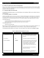
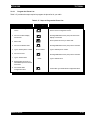
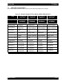
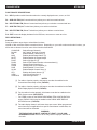
Table 2-3. Some DOS Commands
DOS Command
What it means...
A:
Go to drive “A.”
B:
Go to drive “B.”
C:
Go to drive “C.”
CD\
Return to the Root Directory. CHDIR is the same as CD.
CD DIRNAME
Change directory to the directory named “dirname.” Maximum directory length is 8 characters.
cd used alone will display the current working path name.
COPY B:*.* A:
Makes an identical copy of all files. The *.* means all files within the directory specified. You
can also copy files in the same directory giving the file a different name as the second argument
to copy command, and you can combine several files into one file or append files. In all cases,
the first argument is the source file (the one to copy from) and the last argument is the target file
(the one to copy to).
DEL Filename
Deletes the filename in the current directory
DEL *.*
CAUTION: Files cannot be recovered after executing this command. Delete all files in
current directory
DIR
Lists the files in the current working directory. You can list files in other directories also by
specifying a path name following the command. If you have more files than will fit on the
display, you can type DIR/P, which will make DOS pause when the display is full. Pressing any
key resumes the listing. DIR/W specifies a wide display (5 columns) of file names.
DISKCOPY B: A:
Copies the contents of the disk in drive B to the disk in drive A. Drives must be of the same size
and density. If your drives are not the same size and density, use the same drive name twice,
such as DISKCOPY A: A:.
FORMAT A:
Format an unused, new or old diskette in drive A of the computer so it will accept MS-DOS files.
MD DIRNAME
Makes a new subdirectory called “dirname” of 8 characters or less. You substitute your
directory name for the italicized word dirname. MKDIR is the same as MD.
PROMPT $P $G
Change the display's prompt to include the current working directory's drive and path name,
followed by the “>” sign. This sign is typically seen in the AUTOEXEC.BAT file.
PATH
Set a command search path (such as PATH=C:\MRSS\MTSX\ARCHIVE). This tells the
computer to search this directory after the working directory when a command is entered. This
sign is typically seen in the AUTOEXEC.BAT file.
RD DIRNAME
Remove a subdirectory called “dirname”. Removal of the subdirectory requires that it be empty.
Files can be deleted by the DEL command. RMDIR is the same as RD.
VER
Prints MS-DOS version installed on the computer, such as MS-DOS Version 5.0.
XCOPY
Copies files and directories, including all subdirectories. This command uses disk space more
efficiently and can speed up file access time.
For further information on these and other commands, consult your MS-DOS User’s Manual.
2-8
68P81074C50
MTSX RSS
GETTING STARTED
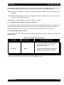
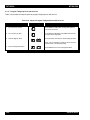
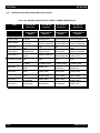
You may have noticed some special characters in the preceding table (*). Certain keyboard characters mean
special things to DOS. Some of these are:
Table 2-4. Special DOS Command Characters
Special DOS Character
What it means...
*
Wildcard character. You can substitute this character for any type or
quantity of characters/digits that follow (not precede) it.
\
Backslash. A special character to separate directories
when specifying path names. By itself, it also represents the root
directory.
?
Wildcard character meaning you can substitute/match it for any
single-digit or character.
/
Front slash. Used for setting options of commands.
There are a couple limitations you may want to know about DOS, RSS files, and directories.
1)
First, DOS only allows file names to be 8 characters long. However, file names can have an optional
1, 2 or 3-character extension after the file name. The extension must be separated from the file name
by a period (sometimes called a dot).
2)
Second, DOS allows only 111 files under the root directory (topmost) on any diskette or hard disk. We
highly recommend that you further subdivide your files into more directories before you accumulate
this many files in any directory, not just the root directory. It’s very confusing and time-consuming to
work with or view this many files at once.
3)
Last, the maximum number of files allowed by the RSS in any non-root directory, whether diskette or
hard disk, is approximately 400. This is an RSS limitation, not a DOS or computer limitation. If you
have more than 400 files, create another directory.
The RSS is not a Microsoft Windows program. The RSS can be executed only from the DOS prompt on
computers which are not running Microsoft Windows.
68P81074C50
2-9
GETTING STARTED
MTSX RSS
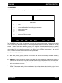
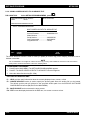
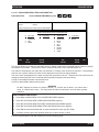
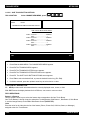
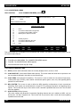
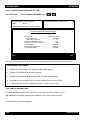
2.5 WHAT’S ON THE RSS DISKETTES
Below are the files located on the diskettes you received with this manual.
File Name
File Type
Description
These files are in the top ROOT directory
DISK #1
INSTALL.EXE
installation file
RSS Installation program. Change to the floppy drive &
type install to begin.
INSTALL.DAT
installation file
Installation Data
MTSXINS.001
executable files
This is a compressed version of the file that the install
program uncompresses during installation to your hard
disk.
DISK.ID
installation file
Installation Data
DISK.ID
installation file
Installation Data
MTSXINS.002
executable files
This is a compressed version of the file that the install
program uncompresses during installation to your hard
disk.
DISK #2
A file can be a program (a set of commands to tell the computer what to do), or a collection of data or information.
As mentioned in the DOS section, DOS files generally have two parts - a file name followed by a file extension,
which is optional. The extension provides an easy way to, at a glance, identify or tag files for easy grouping or
categorizing. In the computer world, some file extension naming conventions have evolved, and Motorola uses
these conventions in the RSS, as you may have noticed.
Now you know what’s on the RSS diskettes we supply. Next you’ll learn how to organize your own disk and
diskettes that you’ll use to store your radio archive files. We suggest that frequent RSS users and computer pros
skip the “ORGANIZING YOUR HARD DISK AND DISKETTES” section and join us back in the “STARTING THE
RSS” section. New users should read all sections.
2-10
68P81074C50
MTSX RSS
GETTING STARTED
2.6 ORGANIZING YOUR HARD DISK AND DISKETTES
When you first start using computers you typically do not have a lot of files to organize. But after a while it gets
increasingly difficult to distinguish between file types, to pick out a specific file in a long list, to keep track of
what’s in which file, or to remember which files are similar in content. Therefore, it’s important to spend some time
now deciding which types or groups of files should be located together in a common place, called a directory.
You can make directories using the DOS MD or MKDIR commands (or inside the RSS via the FILE
MAINTENANCE MENU).
You may want to organize your directories first by customer area, then by customer name, and finally by radio
model type, or perhaps in the reverse order. Consider the different ways in which you operate your business - do
you separate radio files by customer location, by sales revenue, by fiscal year, or perhaps by date of purchase?
When deciding how to organize your files and directories, we suggest a few things:
•
First, we advise you to put as few directories as possible near the top, or root, of your directory tree,
considering your future growth too. (For example, if you have 100 customers within 4 geographical
areas, we suggest your first level of sub directories be the areas that encompass the customer. The next
level of directories would be the customer names within each of those areas.) The idea is to make the
root system spread out wider the deeper you grow, similar to a pyramid shape.
•
Keep the RSS diskette contents in one directory and your archive files in a different directory.
•
Keep archive files in separate directories according to radio model type (MT, MTX, MTS, etc). It is not
possible to know a file’s model type by looking at the file name. Have a separate directory name for each
radio model, then store the archive files for that specific model within the appropriate model directory.
This way archive files for multiple model types are not located in the same directory.
•
The last point we recommend is to dedicate and create a separate diskette for your backup files; always
make backup copies of your files. If you routinely store archive files on your hard disk, make backup
copies of your files on a diskette.
68P81074C50
2-11
GETTING STARTED
MTSX RSS
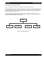
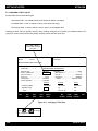
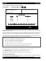
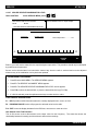
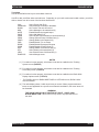
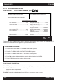
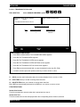
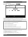
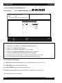
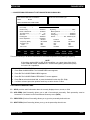
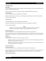
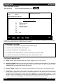
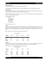
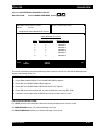
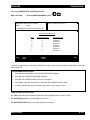
2.6.1 Organizing Your Hard Disk
Below is a sample directory tree for storing your radio archive files on your computer’s hard disk. Though your
hard disk directory tree may be a little different based upon your way of doing business, this setup may be a
starting point for you. The install program will automatically create the MRSS and MTSX directories for you if they
do not exist.
We suggest that you execute the following command before starting. If you place it in your autoexec.bat file, it will
be executed every time the computer is started. PROMPT $P$G. The prompt will the show your current location
in the directory tree. Note how the prompt changes when the following commands are typed to change
directories. The prompt is shown in bold face.
C> prompt $P$G
C:\> CD\mrss
C:\mrss\>
ROOT
SPREAD SHEET
Etc.
WP
SPECTRA
DATA BASE
MRSS
STX
VISARPP
SABER SI
ARCHIVE
SECURITY
MTSX
Etc.
EXECUTABLE PROGRAM FILES
1993
FIRE
GRAPHICS
1994
TOWING
COURIER
FIRE
SECURITY
TOWING
COURIER
Figure 2-2. Hard Disk Directory Tree
2-12
68P81074C50
MTSX RSS
GETTING STARTED
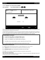
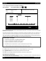
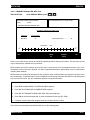
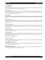
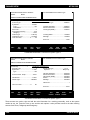
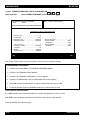
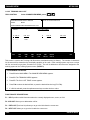
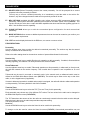
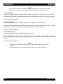
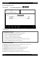
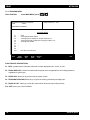
2.6.2 Organizing Your Archive File Diskettes
Below is a sample diskette directory tree for storing your radio archive files on a diskette.
Organizing a diskette is easier due to smaller space on a diskette. Though your tree may be different based upon
your way of doing business, this set-up may be a starting point for you. Be sure to label your diskettes accurately,
such as “1993 MTSX Archive Files”. Depending on the size of your business, you may even have a separate
diskette for FIRE, one for SECURITY, etc.
To create the directory tree shown in Figure 2-3 on your diskette, follow the steps on table 2-6. After each
command, press Return or Enter. This exercise assumes you are using drive A and the diskette contains only
MTSX archive files (not RSS files and not backup files).
ROOT
FIRE
SECURITY
TOWING
COURIER
Figure 2-3. Diskette Directory Tree
68P81074C50
2-13
GETTING STARTED
MTSX RSS
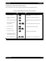
Table 2-6. Steps to Create Diskette Directory Tree
Instruction
What to Type
Explanation
1.
Create diskette label
Label formatted diskette to correspond to the
contents of the diskette such as “MTXS Archive
Files”. Don’t apply it to the diskette yet.
2.
If no hard disk, load DOS
See Table 2-3 to load DOS using drive A. Remove
DOS diskettes after loading. If not at the root
directory of drive A, type: A:cd\
3.
Put new diskette in A
Insert a new diskette into A. Close the drive door.
4.
Format diskette
5.
Label diskette
Remove formatted diskette; apply label without
covering the exposed magnetic area.
6.
Insert diskette again
Insert diskette into drive A again. Close door.
7.
Start at root
CD \
Move (change directory) to the root (uppermost)
directory of the diskette. Omit if already at root
level.
8.
Make FIRE directory
MD FIRE
Make a directory under Root called “FIRE”.
9.
Make SECURITY directory
MD SECURITY
Make a directory under Root called “SECURITY”.
10.
Make a TOWING directory
MD TOWING
Make a directory under Root called “TOWING”.
11.
Make a COURIER directory
MD COURIER
Make a directory under Root called “COURIER”.
12.
Create other directories
2-14
FORMAT A:
Format the new diskette in drive A. Discard diskette
if errors occur.
Make more directories for each additional category
you may need.
68P81074C50
MTSX RSS
GETTING STARTED
2.7 STARTING THE RSS
You have accomplished a lot so far - you have identified and assembled the hardware, you acquired knowledge
of basic computer and DOS concepts, and how to organize disks. You are now ready to start the RSS on your
computer. This section, approximately 30 minutes long, will explain when to install, reinstall, or discard the RSS
diskettes. It will guide you through installation process of the RSS on a hard disk, and finally, it lists how to start
the RSS with the appropriate executable command.
2.7.1 Making a Backup Copy of RSS Diskette(s)
As with any program, it is important to make a backup copy of the RSS diskette before you begin to use it.
Whenever you receive a new version of the RSS, you should make a backup copy.
We recommend a backup copy of your RSS, even if you have a hard disk. To make a backup copy, follow the
steps below. These steps assume you have one diskette drive named A or you have two diskette drives that are
not the same size and density, and that DOS is loaded.
Note
DISKCOPY will not copy from one drive to another if the drives are not the exact same size and density.
Table 2-7. Steps to Backup the RSS Diskette(s)
Instruction
1.
Insert RSS diskette
2.
Make the backup copy
3.
Keep originals safe
68P81074C50
What to Type
Explanation
Put supplied RSS diskette into
drive A; close the door
DISKCOPY A: A:
This copies the data on the source
diskette in drive A (supplied RSS diskette) to the
target diskette (the newly formatted diskette).
Caution: accidentally reversing the insertion
order of the diskettes will erase the contents of
the RSS diskette. DOS will tell you when to insert
the source diskette (RSS one) and when to insert the
target diskette (the newly formatted one). When the
diskcopy is complete, use the target diskette as the
new working copy.
Store the original RSS diskettes in
a safe place away from magnets, moisture, heat and
possible damage.
2-15
GETTING STARTED
MTSX RSS
2.7.2 What To Do with Previous Versions of RSS Diskettes
After you have created a backup copy of the new RSS diskettes, you may wonder what to do with the previous RSS
versions you may have accumulated. We recommend discarding the older versions so that you do not accidently
program the radio with outdated data.
2.7.3 Starting the RSS From the Hard Disk
A hard-disk drive installation program is on the RSS diskettes. After installing the RSS on your hard disk, follow the
startup procedure.
2.7.4 Installing the RSS on Your Hard Disk
Install the latest RSS version as soon as you receive it. Using the install program on the diskettes you received with
this manual assures that you have the latest and greatest version of the RSS. It also keeps important files in a
consistent place for cross-referencing and future use. The software installation takes approximately three minutes.
The install program will:
•
Create the MRSS, MTSX and ARCHIVE directories, if they are not already there.
•
Write over the old version’s program files with the same name, if present.
The install program will not:
•
Write over your archive files.
Before doing the installation steps that follow, be sure you have made a backup copy of the RSS, explained in the
“Making a Backup Copy of RSS Diskette(s)” section and Table 2-7 “Steps to Backup the RSS Diskette(s).”
The steps below install the RSS on your computer. After each “What to Type” step below, press Return or Enter.
Table 2-8. RSS Hard Disk Installation Procedure
Instruction
What to Type
Explanation
Insert the RSS Diskette into Drive A (close the
1. Put RSS diskette in drive A.
door), later you will be instructed to insert the
other one.
2. Go to drive A.
A:
This tells the computer to work from drive A.
3. Start the installation.
INSTALL
This transfers the RSS to your hard disk. Follow
directions and answer questions on the display
when they appear. You will be instructed to
switch diskettes in the diskette drive (for
example, “INSERT DISK CONTAINING FILE
...”).
When the prompt returns, you may start the
RSS (see next section).
4. Store diskettes in safe place
Keep the RSS diskettes in a safe place and
start RSS from the hard disk from now on.
2-16
68P81074C50
MTSX RSS
GETTING STARTED
After installing the RSS on a hard disk, you may notice a .BAT extension and a .ODB extension. These types of
files are explained briefly below. Do not delete or move these files from the C:\MRSS\MTSX directory.
.BAT A batch file. The INSTALL command file creates a file called MTSX.BAT in the top level directory of the
hard drive.
.CFG Created and modified by the RSS, the configuration file (.CFG) contains the PC port choice, the default
pathnames, and the display-type data.
.ODB Used by the RUNTIME.EXE file to properly configure your radio.
2.7.5 Installing the RSS on Multiple Computers or Networks
You may install the RSS on several personal computers and laptop computers at a single site, according to your
license. If you have additional sites (a second shop, etc.) then you should purchase additional subscriptions.
Now that you have a backup and working copy of the RSS, you will start the RSS in the next section.
2.7.6 Hard Disk RSS Startup Procedure
To start the RSS from your hard disk, follow the steps in the table below. After each “What to type” step, press
Return or Enter.
Table 2-9. Hard Disk Startup Procedures
Instruction
1. Move to C drive.
2. Start the RSS
What to Type
C:
MTSX
How to do it/What it Means
Work from hard disk, the C drive. If you have a
hard disk and you bring up your computer with
no diskettes in the diskette drives, you will
already be at the C drive.
This command starts the RSS. If it does not start
correctly, you may hear a tone or see an error
message or error code printed on the display.
After you start the RSS from the hard disk, you will see the BANNER screen.
68P81074C50
2-17
GETTING STARTED
MTSX RSS
2.7.7 The Banner Screen
When the program correctly loads, you will see a “BANNER” screen with the Motorola logo and copyright
information.
Once the program is loaded, press any key. You will then see the MAIN MENU.
MOTOROLA
RADIO SERVICE SOFTWARE
for the
MT2000, MTX8000, MTX9000 and MTS2000
Radios
<Version>
<DATE>
(C) Copyright MOTOROLA Inc. 1994-1996. All rights reserved.
Figure 2-4. The Banner Screen
2-18
68P81074C50
MTSX RSS
GETTING STARTED
2.7.8 The Main Menu
After pressing any key at the BANNER screen, the MAIN MENU appears.
MOTOROLA Radio Service Software
MTSX
Model:
Select Function F1 - F10.
MAIN
MAIN MENU
F1
F2
F3
F4
F5
F6
F7
F8
F9
F10
F1
HELP
-
HELP
SERVICE: Alignment (Requires RIB)
GET/SAVE/PROGRAM/CLONE Codeplug Data From/to Disk/Radio
CHANGE//VIEW Radio Codeplug Data
PRINT Radio Codeplug Data
FILE Maintenance
FLASHport Upgrade
SETUP Computer Configuration
EXIT Radio Service Software, Return to DOS
F2
SERVICE
MENU
F3
GET
SAVE
F4
CHANGE
VIEW
F5
PRINT
MENU
F6
FILE
MAINT
F7
F8
FLASHPORT
UPGRADE
F9
SETUP
MENU
F10
EXIT TO
DOS
Figure 2-5. The Main Menu
From here you can begin to program a radio, but first we will explain how to move around within the menus and
screens of the RSS with the keyboard keys. The parts of the menu are described in the “Anatomy of a Menu”
section.
2.8 NAVIGATING THROUGH THE RSS MENUS
You have successfully started the RSS and are ready to learn just what it is you see on the display, how to move
around, how the RSS is organized, how to change the feature choices, and finally, how to exit.
Now that the RSS MAIN MENU is on your display, to proceed any further you may want to know about the
keyboard keys and what they do. Below is a picture of a typical computer keyboard.
Figure 2-6. The Computer Keyboard
68P81074C50
2-19
GETTING STARTED
MTSX RSS
2.8.1 The Keyboard Keys and Their Functions
Every action of the RSS is controlled by you through the use of formatted displays and function keys. The
function keys are the ten keys labeled F1 to F10 grouped on the left hand side of the keyboard, but be aware that
some other keyboards may have twelve keys labeled F1 to F12 across the top of the keyboard.
F1
F1 - Displays help information on every screen and menu. This on-line help provides
information on how to use the currently displayed menu, screen, line or field. You may
also find system setup information. In many cases the help provided is for the specific
line currently highlighted on the screen.
F2
F3
F4
F5
F6
F7
F8
F9
F2 - F9 - The F2 through F9 keys perform special functions and actions which can vary
from menu to menu and screen to screen. On some screens, F5 will print the current
screen to your printer, and F8 will save the data and options currently displayed.
F10
F10 - Exit to previous menu or screen. The F10 key moves the display backward in the
RSS tree, one screen or menu at a time. F10 performs this function on every menu and
screen. At the MAIN MENU, F10 exits the RSS program.
Esc
Esc - Exit to MAIN MENU. Esc performs this function on every menu and screen.
Tab
Tab - Accepts data currently in a field then moves the prompt forward one field. If entry is
not accepted, an error beep will sound. This key performs exactly like the Enter or
Return key.
Enter or Return
Enter or Return - Accepts data currently in a field then moves the prompt forward one
field. If the entry is not accepted, an error beep will sound. This key is usually two or four
times as large as the letter keys on the keyboard. This key performs exactly like the Tab
key.
2-20
68P81074C50
MTSX RSS
Shift
+
GETTING STARTED
Tab
Back Tab (Shift + Tab) - Accepts data currently in field then moves prompt backward
one field at a time. To back tab, press and hold Shift key and press the Tab key.
Left Arrow - Moves cursor left one space. The Backspace key will also move the
cursor backward (left) one space at a time. Num Lock key must be off.
Right Arrow - Moves cursor right one space. Num Lock key must be off.
Up Arrow - Scrolls through selections, or increases the current relative value. On
some keyboards, the Num Lock key must be off.
Down Arrow - Scrolls through selections, or decreases the current relative value. On
some keyboards, the Num Lock key must be off.
Back
Space
or
Back Space - Erases the current character in the field and moves cursor one space
backward (left). The backspace key on some keyboards is a left arrow. On some
keyboards, the Num Lock key must be off.
Del
Del - Erases current character in field.
PgUp
PgUp - Displays the previous page information on the screen. This is on the numeric
keypad on the right side of the keyboard. On some keyboards, the Num Lock key
must be off.
PgDn
PgDn - Displays the next page of information on the screen. This is on the numeric
keypad. On some keyboards, the Num Lock key must be off.
68P81074C50
2-21
GETTING STARTED
MTSX RSS
2.8.2 Anatomy of a Menu
Within the RSS, there are menus that will take you to screens where you can change the choice or value of a
field. The only difference between a menu and a screen is the information shown in the working area, shown as C
in the figure below. A menu or screen has four areas, labeled below as A, B, C and D.
MOTOROLA Radio Service Software
MTSX
Model: H01WCF4DB5AN
Select Function F1 - F10.
B
A
MAIN
MAIN MENU
F1
F2
F3
F4
F5
F6
F7
F8
F9
F10
F1
HELP
-
HELP
SERVICE: Alignment (Requires RIB)
GET/SAVE/PROGRAM/CLONE Codeplug Data from/to Disk/Radio
CHANGE/CREATE/VIEW Radio Codeplug Data
PRINT Radio Codeplug Data
FILE Maintenance
C
FLASHport Upgrade
SETUP Computer Configuration
EXIT Radio Service Software, Return to DOS
F2
SERVICE
MENU
F3
GET
SAVE
F4
CHANGE
VIEW
F5
PRINT
DATA
F6
FILE
MAINT
F7
D
F8
FLASHP ORT
UPGRADE
F9
SETUP
MENU
F10
EXIT
TO DOS
Figure 2-7. An RSS Menu
A
RSS Location ID Area. In this area you will find the words MOTOROLA Radio Service Software and
a menu or screen pathname for the current menu or screen shown on the display. Each menu and
screen name will be separated by a colon (:). For some examples of this pathname, glance ahead in
this manual to see the menus and screens that are deeper into the RSS tree (past the MAIN MENU,
the highest root level, which is the assumed, default starting point). If a radio is connected, the
current radio model being read will also be displayed in this area.
B
Instruction Area. This area tells you the allowable actions for the current menu or screen. It is
divided into 4 lines; the first two lines are reserved for messages to the user, and the last two lines
are status lines.
C
Working Area. This area of a menu (not a screen) displays a list of functions (menu choices) you
can execute from the current menu. Each menu-item is preceded by an F-number key (function key).
Pressing an F-number key advances you to another menu or screen (see Figure 2-10).
D
F-Key (Function Key) ID Area. This area displays the F-number keys and function names for the
current menu or screen.
NOTE
All functions (supported and unsupported) will be displayed in the menu’s working area. The unsupported
functions (based on the radio’s model or options) will NOT be displayed in the F-key ID area.
2-22
68P81074C50
MTSX RSS
GETTING STARTED
2.8.3 Anatomy of a Screen
As stated before, the only difference between a menu and a screen is the contents of the working area, shown as
letter C in the previous menu figure, and shown below as the Working area. Screens list features (fields) that can
be viewed or edited.
MOTOROLA Radio Service Software
MTSX
Model:
Enter or Scroll to Select
Personality.
MAIN:CHANGE/VIEW:CONV:PERS
Personality ................1
CONVENTIONAL PERSONALITY
Receive Only .................................Disabled
Direct / Talkaround .........................Enabled
Time Out Timer .............................3 60
Scan List .............................................None
Hot Keypad ....................................Disabled
Phone Operation...........................Unlimited
Frequency (MHz)
Signalling Type
Code
F1
HELP
F2
ADD
PERS
F3
PREV
PERS
F4
NEXT
PERS
Signalling ............................................MDC
MDC System # .......................................1
PTT ID ........................................Disabled
Emergency ..................................Enabled
Revert ...............................Selected Chan
Receive
Transmit
Direct
935.06250
CSQ
896.01250
PL
67.0 Hz XZ
896.01250
DPL
023
F5
DELETE
PERS
F6
F7
MDC
OPTIONS
F8
PHONE
OPTIONS
F9
MORE
OPTIONS
F10
EXIT
Figure 2-8. An RSS Screen
The working area of a screen contains a list of programmable features called “fields” that can be selected or
changed using the arrow, tab or return keys described earlier. On some screens are features that can be selected
for each individual channel (hereafter we will refer to a channel as a “mode”); these features are selected on a
“per-mode” basis. On other screens are features that can be selected for all modes of the radio (“radio-wide”
features).
68P81074C50
2-23
GETTING STARTED
MTSX RSS
And still other screens list those features that perform a certain RSS function, such as servicing the radio or
printing the personality data.
2.8.4 A Complete Menu Mapping at a Glance
The screens are organized in a tree-root fashion (Figure 2-9). Though this tree-root system is shown sideways in
the following picture, it shows how the whole system starts with a main root (MAIN MENU) at the left side and
branches outward from the main root. This branching grows deeper as you get closer to the precise screen which
contains the feature you want to program into the radio.
Traveling from one RSS menu or screen to another is similar to the way a car must use the road system to drive
to the other side of a lake, instead of flying directly as a plane would. To move forward from one screen to
another, use one of the F-keys until you’ve reached the menu that contains the other screen you want. To back
up, use the F10 key. Each time you press F10 you retreat to the previous screen or menu, moving closer to the
MAIN MENU.
2-24
68P81074C50
MTSX RSS
GETTING STARTED
MAIN
MENU
F1
F2
HELP
F4
F3
SERVICE
GET/
SAVE/
PROGRAM
F5
CHANGE/
VIEW
PRINT
MENU
F6
F7
F8
FILE
FLASHPORT
MAINTENANCE
UPGRADE
F9
F10
EXIT TO
SETUP
DOS
F2 - Create Directory Path
Refer to the
following page.
F5 - Delete Archive File
F3 - PC
Configuration
F2 - Reading Codeplug Data From the Radio
F7 - Screen Color
Configuration
F3 - Reading Codeplug Data From an Archive File
F4 - TCMS Merge
F5 - Radio Cloning
F2 - View Radio Configuration
F7 - Saving Codeplug Data to an Archive File
F3 - View FLASHkey Configuration
F8 - Programming the Radio’s Codeplug
F8 - Upgrade Radio
F9 - Programming History
F2 - Transmit Alignment Menu
F2 - Reference Oscillator Alignment
F3 - Transmit Power Alignment
F4 - Transmit Deviation Balance (Compensation) Alignment
F5 - Transmit Deviation Limit Alignment
F6 - Transmit Deviation Limit Alignment: Reference Softpot
F3 - Radio Wide Buttons, Scan,
Phone
F4 - Trunking Systems, Personalities,
Options
F6 - Conventional Personalities
F7 - Transmit VCO Crossover Alignment
F8 - Secure Transmit Deviation
F3 - Receive Alignment Menu
F8 - Zone Summary
F9 - Radio Codeplug Data Summary
F2 - Front End Filter Alignment
F3 - Rated Audio Alignment
F4 - Squelch Attenuator (12.5kHz) Alignment
F5 - Squelch Attenuator (20kHz) Alignment
F6 - Squelch Attenuator (25/30kHz) Alignment
F7 - RX VCO Crossover Frequency
F8 - Secure Receive Discriminator Level
F4 - Signalling Alignment Menu
F2 - DTMF Transmit Deviation
F3 - Transmit Signalling: High Speed
F4 - Transmit Signalling: MDC 1200
Figure 2-9. RSS Menu Mapping at a Glance (page 1 of 2)
68P81074C50
2-25
GETTING STARTED
MTSX RSS
MAIN
MENU
F4
CHANGE/
VIEW
F3 - Radio Wide Configuration Menu
F2 - Radio Wide Options
F6 - Radio Wide Secure Options
F7 - Radio Wide Emergency Options
F9 - More Radio Wide Options
F3 - Radio Wide Features Configuration Menu
F2 - Radio Wide Button Configuration
F3 - Radio Wide Switch Configuration
F4 - Radio Wide Menu Item Configuration
F4 - Phone Configuration
F8 - DTMF Access/Deaccess Codes
F9 - Dial Options
F5 - Radio Wide Scan Lists And Options
F8 - Radio Wide Scan Options
F6 - Radio Wide Display Options
F4 - Trunking Menu
F2 - Trunking Radio Wide Options
F2 - SmartZone Environment
F3 - Voice On Control
F3 - Trunking Systems
F6 - Control Channel
F9 - Trunking System Options
F5 - One Touch
F6 - Trunking Status Alias
F7 - Trunking Message Alias
F4 - Trunking Personality
F7 - Trunking Talkgroup
F8 - Emergency Data Configuration
F9 - Trunking Personality Options
F6 - SmartZone Preferred Sites
F5 - Trunking Call List
F6 - Conventional Menu
F2 - Conventional Radio Wide Options
F3 - Conventional Personality Options
F6 - Conventional Secure Personalities
F7 - Personality MDC Options
F8 - Conventional Personality Phone Options
F9 - More Conventional Personality Options
F4 - MDC Configuration Menu
F3 - MDC Systems
F9 - More MDC System Options
F7 - Auxiliary Systems
F2 - Singletone Systems
F3 - Singletone List
F4 - Quick Call II Systems
F5 - GE Star Systems
F8 - Zone/Talkgroup (Channel) Assignment
Figure 2-9. RSS Menu Mapping at a Glance (page 2 of 2)
2-26
68P81074C50
MTSX RSS
GETTING STARTED
2.8.5 The Relationship Between Screens
Some screens contain fields that require or take values from other screens and features, and thus are dependent
upon each other. For example, the signalling system values specified on the CHANGE/VIEW:CONV:PER are
“assigned” at the CHANGE/VIEW:CONV:MDC:SYSTEM screen.
MOTOROLA Radio Service Software
MTSX
Model:
Enter or Scroll to Select System.
MAIN:CHANGE/VIEW:CONV:MDC:SYSTEM
MDC System............1
MDC SYSTEM
Primary ID (Hex) ....................................0001
Secondary ID (Hex) .......................00000000
Variable ID (Hex) .....................................000
Leading PTT-ID ................................Enabled
PTT-ID Sidetone ...........................Disabled
Trailing PTT-ID ................................Disabled
Radio Check ....................................Disabled
F1
HELP
F2
ADD
SYS
F3
PREV
SYS
F4
NEXT
SYS
F5
DELETE
SYS
Emergency Type ..........................Enabled
Emergency Type .....................Alarm Only
PTT ID Sidetone........................Enabled
Acknowledge Alert Tone ...........Enabled
Revert Table
Num
1
2
3
F6
Zone
1
1
1
F7
Channel
1
1
1
F8
F9
MORE
OPTIONS
F10
EXIT
Figure 2-10. Relationship Between Screens
68P81074C50
2-27
GETTING STARTED
MTSX RSS
2.9 CHANGING A FIELD VALUE
Screen fields come in three basic types:
Information fields - non-editable fields which cannot be altered or changed.
Scrollable fields - to edit or change a choice, press the arrow key(s).
Direct-entry fields - to edit or change a choice, type in an acceptable value.
Changing a field’s value is typically done by either scrolling through a list of options (in scrollable fields) or by
typing in a correct value (in direct-entry fields). Scrolling is done with the arrow keys.
Press Tab or Enter to
move to field, then type
new value.
MOTOROLA Radio Service Software
MTSX
Model:
Enter or Scroll to Select
Personality.
MAIN:CHANGE/VIEW:CONV:PERS
Personality ................1
CONVENTIONAL PERSONALITY
Receive Only .................................Disabled
Direct / Talkaround .........................Enabled
Time Out Timer..............................3 60
Scan List .............................................None
Hot Keypad ....................................Disabled
Phone Operation...........................Unlimited
Frequency (MHz)
Signalling Type
Code
F1
HELP
F2
ADD
PERS
F3
PREV
PERS
F4
NEXT
PERS
Signalling ............................................MDC
MDC System # .......................................1
PTT ID ........................................Disabled
Emergency ..................................Enabled
Revert ............................Selected Chan
Receive
Transmit
Direct
935.06250
CSQ
896.01250
PL
67.0 Hz XZ
896.01250
DPL
023
F5
DELETE
PERS
F6
F7
MDC
OPTIONS
F8
PHONE
OPTIONS
F9
MORE
OPTIONS
F10
EXIT
Figure 2-11. Changing a Field Value
Press
or
to change
field, or type new value.
2-28
68P81074C50
MTSX RSS
GETTING STARTED
2.10 SETTING (CONFIGURING) THE RSS COMPUTER DEFAULTS
Now that you are aware of how fields, screens and menus relate to one another, this section introduces the
concept of saving certain default computer information. Setting the computer defaults eliminates the need to
specify them every time you enter the RSS or program a radio.
Read this section if you want to:
1.
Set a default file path name so you won’t have to specify it every time you save a radio archive file,
2.
Set or change the default port used to interface with the radio and RIB,
3.
Set the default colors you see on your RSS screen.
If you’ve been with us from the start, you should be at the MAIN MENU. If you’ve just joined us or got lost inside
the RSS screens, press Esc to get to the MAIN MENU. From the MAIN MENU, press F9 to get to the SERVICE
SOFTWARE CONFIGURATION MENU.
From the SERVICE SOFTWARE CONFIGURATION MENU you can either read the on-line help, set some
default computer values, or exit. Pressing F3 on the SERVICE SOFTWARE CONFIGURATION MENU will
display the CONFIGURE COMPUTER screen, where you can specify the default drive and path names for future
archive files. Pressing F7 on the SERVICE SOFTWARE CONFIGURATION MENU displays CONFIGURE
SCREEN where you can specify the colors for your screen’s text, lines, background and highlighted fields.
ISS.
LETTERING SIZE:
REQUIRES:
MOTOROLA Radio Service Software
MTSX
Model: H01WCF4DB5AN
O
A
MAIN:CONFIGURATION
SERVICE SOFTWARE CONFIGURATION
F1
F2
F3
F4
F5
F6
F7
F8
F9
F10
F1
HELP
-
HELP
F2
F3
CONFIGURE
PC
PC CONFIGURATION, Drives, Paths, Ports, etc.
SCREEN Color Configuration
Exit, Return To Main Menu
F4
F5
F6
F7
SCREEN
COLORS
F3
MOTOROLA Radio Service Software
MTSX
Model: H01WCF4DB5AN
F8
F9
F10
EXIT
F7
MOTOROLA Radio Service Software
MTSX
Model: H01WCF4DB5AN
Enter Path Name.
MAIN:CONFIGURATION:SCREEN COLORS
MAIN:CONFIGURATION:PC
SCREEN COLORS
CONFIGURE PATHS AND PORT
MONITOR TYPE . . . . . . . . . . . . . . . Color
TEXT . . . . . . . . . . . . . . . . . . . . . . . Yellow
STATUS TEXT . . . . . . . . . . . . . . . Yellow
MESSAGE TEXT . . . . . . . . . . . . . White
HIGHTLIGHT . . . . . . . . . . . . . . . . Green
BACKGROUND . . . . . . . . . . . . . . Blue
FRAME. . . . . . . . . . . . . . . . . . . . . . Red
SELECTED TEXT . . . . . . . . . . . . . Yellow
POPUP BACKGROUND. . . . . . . . Brown
Archive Path:....
FLASH Software Path:....
SRIB Software Path & Filename:....
System Key:....
TCMS Path:...............
RIB...................................COM 1
F1
HELP
F2
F3
Use Up/ Down arrows to Select.
F4
F5
F6
COM
TEST
F7
F8
SAVE
F9
F10
EXIT
F1
HELP
F2
F3
F4
F5
F6
F7
F8
SAVE
F9
F10
EXIT
Figure 2-12. Service Software Configuration Menu Options
68P81074C50
2-29
R
GETTING STARTED
MTSX RSS
2.10.1 Setting Default Archive and Backup Paths
First, you can set the drive name and path names for archive files you will create later. Specifying a default path
name here will save much typing time later every time you go to save an archive file. Here’s how to set the
default archive and backup file paths.
Table 2-10. Creating Archive File Paths
Instruction
1. GO to CONFIGURE
COMPUTER
2. Specify archive file path
3. Save this configuration
What to Type
F3
C:\MRSS\MTSX\ARCHIVE
F8
Explanation
Press F3 at the SERVICE SOFTWARE
COMPUTER CONFIGURATION MENU to get
to CONFIGURE COMPUTER.
At CONFIGURE COMPUTER, type this
archive file path name if you have a hard disk.
This is where you will keep your radio archive
files. If you don’t keep archive files on your
hard disk, specify (one of) your diskette
drive(s).
F8 saves the field options displayed on the
screen.
2-30
68P81074C50
MTSX RSS
GETTING STARTED
Next are the steps to specify the serial port you use for interfacing with the radio and RIB. The default port is
COM 1.
2.10.2 Setting a Communications Port
Table 2-11. Setting a Port
Instruction
What to Type
1. Go to CONFIGURE COMPUTER
F3
2. Go to the RIB field
TAB
F6
F8
5. Save this configuration
6. Exit screen when done
68P81074C50
Press F3 at SERVICE SOFTWARE
CONFIGURATION MENU to go to
CONFIGURE COMPUTER.
Pressing Tab , Enter or Return advances to
the next field. Press Tab five times.
Use the arrow keys to scroll through the
available ports. Options are COM 1 or COM
2 on many computers. Some computers will
also have COM 3 and COM 4. Choose the
port where you will connect the computer-toRIB cable.
3. Select a port
4. Test the port
Explanation
F10
You can test the port by pressing F6, COM
TEST - if OK it will beep and in the
Instruction Area (see letter B in Figure 2-7)
of the screen the words “Communication
with the radio was successful” will appear.
F8 saves the field options on the screen.
“Configuration File Written Successfully”
appears in Instruction Area (B) of the
screen.
Press F10 to exit this screen and go to
previous menu.
2-31
GETTING STARTED
MTSX RSS
2.11 EXITING THE RSS
If you want to program a radio, don’t exit yet. Whenever exiting the RSS, always ask yourself these questions:
1. Did you apply the changes to the radio (save to the radio)?
2. Did you apply the changes to a computer file (save archive file)?
If you do want to exit, exiting is very easy - you use the Esc key to return to the MAIN MENU, then press F10/F2
to exit to the DOS prompt.
2-32
68P81074C50
MTSX RSS
GETTING STARTED
2.12 MAIN MENU
RSS LOCATION:
Press any key when instructed on the BANNER Screen.
MOTOROLA Radio Service Software
MTSX
Model:
Select Function F1 - F10.
MAIN
MAIN MENU
F1
F2
F3
F4
F5
F6
F7
F8
F9
F10
F1
HELP
-
HELP
SERVICE Alignment (Requires RIB)
GET/SAVE/PROGRAM Codeplug Data from/to Disk/Radio
CHANGE/CREATE/VIEW Radio Codeplug Data
PRINT Codeplug Data
FILE Maintenance
FLASHport Upgrade
SETUP Computer Configuration
Exit Radio Service Software, Return to DOS
F2
SERVICE
MENU
F3
GET
SAVE
F4
CHANGE
VIEW
F5
PRINT
DATA
F6
FILE
MAINT
F7
F8
FLASHP ORT
UPGRADE
F9
SETUP
MENU
F10
EXIT
TO DOS
The MAIN MENU is the top level of the program from which all function selections start. All selections are made
via the function keys, labeled F1 through F10 on the keyboard. All other menus contain an ESC key, and by
pressing it the operator may at any time return to the MAIN MENU. After making a selection, the user will be
directed to similar menus and/or data entry screens for RF alignment or codeplug data. The user must initially
load data from a radio (or disk) via the GET/SAVE function before being permitted to CHANGE/VIEW any
codeplug data. For any problems not covered by the Radio Service Software Users manual or the service
manual, contact the local MOTOROLA field technical representative.
FUNCTION KEY DESCRIPTIONS:
F1 - HELP when pressed provides additional information on this screen. Generic help is available within any
help screen via the MORE HELP function.
F2 - SERVICE is a multi-level menu that permits access to all radio service alignments via the service screens. A
radio must be connected to the computer via the RIB before access will be permitted to the service screens.
All service screens access the codeplug directly, therefore, it is NOT necessary to read the codeplug data
before using the service screens.
F3 - GET/SAVE is used to read codeplug data from a radio and/or retrieve archived codeplug data from a
diskette or hard disk for editing via the CHANGE/VIEW function. GET/SAVE is also used to program edited
codeplug data back into the radio or to create an archive file on a diskette or hard disk.
68P81074C50
2-33
GETTING STARTED
MTSX RSS
F4 - CHANGE/VIEW is a multi-level menu that is used to change, view, or modify codeplug features and option
configurations. All radio codeplug parameters are classified as either RADIO-WIDE, CONVENTIONAL,
TRUNKED, or PERSONALITY related. CHANGE/VIEW permits access to each of these categories. Unlike
the SERVICE function, a codeplug must be loaded into the computers memory, via GET/SAVE functions,
before CHANGE/VIEW functions can be accessed. An archive file can be accessed without a radio being
connected.
F5 - PRINT MENU will print selected codeplug data.
F6 - FILE MAINTENANCE is available to allow some file manipulation capability without exiting the RSS. New
directories can be created and files can be deleted from this screen.
F8- FLASHPORT UPGRADE is a multi-level menu that is used to view the radio’s configuration, to view the
FLASHkey’s contents, to upgrade the codeplug, and to FLASH the radio.
F9 - SETUP is used to configure the the Radio Service Software to the users particular application. Archive path
names, communication ports, and even screen colors may be customized to the customer’s specific needs.
F10 - EXIT is used to quit the program and return to DOS. Ensure that all desired codeplug changes have been
programmed back to the radio and that an archive copy has been made. If this is not done, all changes will
be lost as returning to DOS erases this data from the computer’s memory.
2-34
68P81074C50
MTSX RSS
GETTING STARTED
2.12.1 How to Read the Codeplug
A. Connect the radio to the computer as shown in Figure 2-1. If you are not already at the MAIN MENU,
press any key at the BANNER screen.
B. From the MAIN MENU press F3; the GET/SAVE/PROGRAM MENU will be displayed.
2.12.1.1 Reading the Codeplug
You may read the codeplug from the radio or from the archive disk. After reading, the codeplug will be checked
for valid serial number, model number, checksums, etc.
2.12.1.2 Reading Codeplug Data from the Radio
Turn the radio on and press F2. A series of status messages will appear in the upper right corner of the screen. If
a communication error occurs, a pop up window will be displayed. If no errors occur, the center of the screen will
display the progress of the codeplug read. The read process will take approximately one minute. After the
codeplug is read, the GET/SAVE/PROGRAM MENU will be displayed.
2.12.1.3 Reading Disk Codeplug Files
Press F3 from the GET/SAVE/PROGRAM MENU. The Disk File Names screen will be displayed. An archive
path and the list of files in that path will be displayed. By default, the path will be the corresponding archive path
specified on the Paths and Port screen. If you want to retrieve a file from another path, press F2, type in the path
name, and then press Enter. The names of the files in the new path will be displayed.
To verify the model number and serial number of the codeplug file before reading it, select the desired file by
pressing Enter, Tab, Shift, or the arrow keys until the desired filename is highlighted.
To retrieve a selected file, press F8. The selected file will be retrieved, validated, and placed in computer
memory. The read process will be displayed on the screen.
68P81074C50
2-35
GETTING STARTED
MTSX RSS
2.13 SETUP CONFIGURATION
RSS LOCATION:
At the MAIN MENU, press
F9
.
MOTOROLA Radio Service Software
MTSX
Model:
MAIN:CONFIGURATION
SERVICE SOFTWARE CONFIGURATION
F1
F2
F3
F4
F5
F6
F7
F8
F9
F10
F1
HELP
-
HELP
PC CONFIGURATION, Drives, Paths, Ports, etc.
SCREEN Color Configuration
Exit, Return to Main Menu
F2
F3
CONFIGURE
PC
F4
F5
F6
F7
SCREEN
COLORS
F8
F9
F10
EXIT
The Setup Computer Configuration screen is accessed by pressing F9 at the MAIN MENU. From this screen, you
may set up the paths for the archive file. You may also setup the serial port (COM 1 or COM 2) that will be used
to communicate with the radio.
FUNCTION KEY DESCRIPTIONS:
F1 - HELP provides useful information about the currently displayed menu, screen, or field.
F3 - CONFIGURE PC is used to set default disk drive paths for archive files and backup files. It is also used to
select which asynchronous communications port (COM 1 or COM 2) the RIB will be connected to. The radio
service software will automatically determine at what clock speed the computer is operating on. No userselectable parameters are required.
F7 - SCREEN COLORS is used to enable the color display option. The standard default configuration for Radio
Service Software is for a monochrome display monitor. However, if the computer is capable of color display
the viewing quality is greatly enhanced. (Refer to your computer’s owner’s manual for a complete
description of path names and asynchronous communication ports.)
F10 - EXIT moves the display backward in the RSS tree, one screen or menu at at time.
2-36
68P81074C50
MTSX RSS
GETTING STARTED
2.13.1 Configuring Paths and Port
RSS LOCATION:
At the MAIN MENU, press
MOTOROLA Radio Service Software
MTSX
Model:
F3
F9
.
Enter Path.
MAIN:CONFIGURATION:PC
CONFIGURE PATHS AND PORT
Archive Path: ....C:\MRSS\MTSX\ARCHIVE
FLASH Software Path:...C:\MRSS\MTSX\UPGRADE
Bootstrap Code Path & Filename: C:\MRSS\MTSX\UPGRADE\MTSXBOOT.ENC
SRIB Software Path & Filename:...C:\MRSS\MTSX\SRIB\SMARTRIB.ENC
System Key: .....C:\MRSS\MTSX\SYSKEY
TCMS Path........C:\MRSS\MTSX\OFP
RIB ...............................COM 1
F1
HELP
F2
F3
F4
F5
F6
COM
TEST
F7
F8
SAVE
F9
F10
EXIT
This screen is used to set default disk drive paths for archive files and backup files. It is also used to select which
asynchronous communications port (COM 1 or COM 2) the RIB (radio interface box) will be connected to.
Refer to your computer’s owner’s manual for a complete description of directory path names and asynchronous
communications ports.
FUNCTION KEY DESCRIPTIONS:
F1 - HELP provides useful information about the currently displayed menu, screen, or field.
F6 - COM TEST (Communications Test) is used to verify that your computer is set up properly and is able to
READ and PROGRAM a radio codeplug properly.
After your computer and RIB are connected per your Radio Service Software manual and you have
selected the appropriate communication port, turn on your radio and execute COM TEST by pressing F6.
COM TEST will verify your system is functioning properly by sending commands to the radio and checking
for the proper response. No codeplug changes will result from these commands. An OK response will be
displayed in the Status Window if the system checks OK. Otherwise, error messages will be displayed.
Consult Appendix A for proper corrective action.
F8 - SAVE is used to save the configuration information to a file on your program disk. Every time you use the
Radio Service Software the configuration that you SAVED last will be used. At anytime the configuration
may be changed and SAVED.
F10 - EXIT moves the display backward in the RSS tree, one screen or menu at at time.
68P81074C50
2-37
GETTING STARTED
MTSX RSS
FIELD DEFINITIONS:
Archive Path
Enter the default directory path where archive files are to be located.
The GET/SAVE — SAVE FILE function will default to this path. Refer to your computer’s owner’s manual for a
complete description of directories and path names.
FLASH Software Path
Enter the default directory path where archive files are to be located. The default path established by the MRSS
installation program is C:\MRSS\MTSX\Upgrade. In order to assure a successful FLASHport Upgrade, it is strongly
recommended that none of the files installed by the MRSS installation program be moved, overwritten by the user,
or renamed. Prior to performing a FLASHport Upgrade, MRSS displays the list of files that exist in the path entered
here. The user is then asked to select the desired FLASHport Upgrade Software Kit and press F8 to start the
upgrade process. Errors such as: UNABLE TO OPEN THE SELECTED UPGRADE FILE, FILE CHECKSUM
ERROR, UNABLE TO OPEN THE SELECTED UPGRADE FILE, or INCORRECT UPGRADE SOFTWARE KIT,
mean that the selected file cannot be accessed, or the selected file has an invalid format (the file is not MRSS
compatible), or the Software Kit No. in the file does not match the one on your FLASHKEY, respectively. In case of
such errors, make sure the selected file is the one that was shipped to you with your upgrade kit.
Bootstrap Code Path & File Name
Enter the default directory path and the default file name for this file. The default path established by the RSS for
this field is “C:MRSS\MTSX\UPGRADE\MTSXBOOT.ENC.
SRIB Software Path & File Name
Enter the default directory path and the default name for the SRIB Software file. The default path established by
the MRSS installation program is C:\MRSS\MTSX\SRIB, and the default file name is SMARTRIB. ENC. In order to
assure a successful FLASHport Upgrade, it is strongly recommended that none of the files installed by the MRSS
installation program be moved, overwritten by the user, or renamed. Errors such as: UNABLE TO OPEN THE
SRIB SOFTWARE FILE, or SRIB SOFTWARE CHECKSUM FILE, UNABLE TO CONTINUE, mean that the
selected file cannot be accessed, or the selected file has an invalid format (the file is not MRSS compatible). In
case of such errors, make sure the selected file is the one that was shipped to you with your upgrade kit.
WARNING
If you install the RSS in a drive or sub-directory other than in the default directory “C:\MRSS\MTSX”, the
above paths for FLASH software, Bootstrap Code, and SRIB software must also be changed.
TCMS Path
Enter the Default directory path from where TCMS Update files will be retrieved. The GET/SAVE — GET TCMS
file function will default to this path. Refer to your computer’s owner’s manual for a complete description of
asynchronous communications ports and how to configure them.
System Key
Enter the default directory path where trunking system keys are to be located. Refer to your computer’s owner’s
manual for a complete description of directories and path names.
RIB
Use the up/down arrow keys to select to which asynchronous communications port (COM 1 or COM 2) your RIB
(radio interface box) is connected.
If you are not sure how your computer is configured or if you have two asynchronous communications ports, first
select COM 1 and use the COM TEST (F6) function to communicate with a radio. If the test fails, select COM 2
and repeat COM TEST. Be sure that all cables and power supplies are connected per the instructions in you radio
service software user’s guide. Refer to your computer’s owner’s manual for a complete description of
asynchronous communications ports and how to configure them.
2-38
68P81074C50
MTSX RSS
GETTING STARTED
2.13.2 Setting Screen Colors
F9
RSS LOCATION:
F7
At the MAIN MENU, press
MOTOROLA Radio Service Software
MTSX
Model:
.
Use Up/Down arrows to Select.
MAIN:CONFIGURATION:SCREEN COLORS
SCREEN COLORS
MONITOR TYPE .............................Color
TEXT............................................Yellow
STATUS TEXT.............................Yellow
MESSAGE TEXT .........................White
HIGHLIGHT .................................Green
BACKGROUND ...........................Blue
FRAME ........................................Red
SELECTED TEXT........................Yellow
POPUP BACKGROUND..............Brown
F1
HELP
F2
F3
F4
F5
F6
F7
F8
SAVE
F9
F10
EXIT
This screen is used to select the type of display monitor that you are using with your computer, that is,
Monochrome or Color.
For proper color operation, you must have a color monitor and the appropriate color display interface card
installed in you computer. Please refer to your computer’s owner’s manual and/or your computer dealer if you
have questions regarding the color capability of your computer.
You may also further customize your screen by selecting colors for the screen’s text, status line, message line,
highlighted text, background, frame, selected text, and popup background.
FUNCTION KEY DESCRIPTIONS:
F1 - HELP provides useful information about the currently displayed menu, screen, or field.
F8 - SAVE is used to save the configuration information to a file on your program disk. Every time you use the
Radio Service Software, the configuration that you SAVED last will be used. At anytime the configuration
may be changed and SAVED.
F10 - EXIT moves the display backward in the RSS tree, one screen or menu at a time.
68P81074C50
2-39
GETTING STARTED
MTSX RSS
FIELD DEFINITIONS:
Monitor Type
Use the UP/DOWN arrow keys to select either a monochrome or color display monitor.
Default = Monochrome.
Text
Use the UP/DOWN arrow keys to select the desired color for screen text.
Default = Light Gray
Status Text
Use the UP/DOWN arrow keys to select the desired color for the status line located in the lower portion of the top
right-side window.
Default = Light Gray
Message Text
Use the UP/DOWN arrow keys to select the desired color for the message line located in the upper portion of the
top right-side window.
Default = Light Gray
Highlight
Use the UP/DOWN arrow keys to select the desired color for the highlighted screen text.
Default = Brown
Background
Use the UP/DOWN arrow keys to select the desired color for the screen.
Default = Black
Frame
Use the up/down arrow keys to select the desired color of the screen outline.
Default = Light Gray
Selected Text
Use the UP/DOWN arrow keys to select the desired color of the selected text.
Default = Light Gray
Popup Background
Use the UP/DOWN arrow keys to select the desired color of the popup background.
Default = Black
Screen configuration changes must be SAVED (F8) before you EXIT (F10) this screen.
2-40
68P81074C50
MTSX RSS
TUTORIAL
SECTION 3. BASIC RADIO PROGRAMMING TUTORIAL
3.1 INTRODUCTION TO SECTION
Now that the hardware and software installation is complete, the RSS is up and running, and you're familiar with
the keyboard and the RSS user-interface, you are ready to personalize a radio. The tutorials that follow will walk
you through the programming of radios with specific features.
The first tutorial walks a new user through the steps to program an MT2000 basic 16-channel conventional radio
and saving the personality to the codeplug and archive files.
The second portion of the tutorial walks you through the process of programming an MTX8000 trunked radio.
The third tutorial involves cloning (copying) the personality data from an archive file of one already programmed
radio to other radios. Cloning is used when there is a need for multiple radios equipped with the same radio
features and functions.
These tutorials list the desired features for the particular application, then give an overview in a list format of the
major steps involved in programming the radio, then finally walks you through the specific steps to program the
features into the radio.
All of the tutorials assume that the RSS is up and the MAIN MENU is displayed. If the MAIN MENU is not
displayed, follow the brief steps below. In all the tutorials, remember F1 displays help information corresponding
to the current highlighted field or current screen. F10 backs you out of the RSS one menu level at a time. Esc
goes directly to the MAIN MENU.
Table 3-1. Quick Steps to Bring Up MAIN MENU
1. Assemble, connect and power up the hardware and computer.
2. After the computer has successfully booted, the prompt will be C:.
3. If you have not yet installed this latest RSS version, make a backup RSS copy (see Section 2.7.1) and install it on
your hard disk. (see Section 2.7.4)
4. Type MTSX
5. Press Return
6. Press any key at the BANNER screen (see Figure 2-4, Section 2.7.7).
7. The MAIN MENU appears.
68P81074C50
3-1
TUTORIAL
3.2
MTSX RSS
PROGRAMMING A BASIC 16-CHANNEL MT2000 CONVENTIONAL RADIO
In this tutorial, we list the desired features, address the major decisions involved, and give step-by-step
instructions for programming the 16-channel conventional portable radio.
3.2.1
Desired Features
Let's assume the following features are desired:
•
•
•
•
16 Transmit/Receive Frequencies
Private Line/Digital Private Line (TPL/DPL) Codes
Assign Scan to the concentric switch and create two scan lists.
Enable Telephone Operation (for full keypad models only)
We will assume that factory defaults are suitable for most parameter values.
3.2.2
Major Decisions Involved
To program the desired features above, the approach with the RSS will be:
1.
2.
3.
4.
Determine desired number of personalities (channels) desired.
Determine desired feature systems to use (basic, scan, signalling).
Determine desired features to program radio-wide (all channels).
Determine desired features to program per-personalities (individual channels only).
3.2.3
High Level Programming Flow
The overview of the flow of programming in this example is as follows:
1. Read the radio.
2. Assign button/switch functions that differ from factory defaults.
3. Create a second scan list (list members not filled in at this time).
4. Set up the phone number list.
5. Create/configure Conventional personalities.
6. Assign personalities to switch positions on Zone/Channel screen.
7. Fill in scan lists with the desired zone/channel entries.
8. Program the radio.
This programming flow was chosen because it minimizes navigation between screens.
3.2.4
Step-by-Step Specific Programming Instructions
We have designed a sample chart (Page 3-3) for a conventional radio for recording the features you wish to
program into your radio. See Appendix E for a blank form you can use for future conventional radios.
3-2
68P81074C50
MTSX RSS
68P81074C50
CONVENTIONAL RADIO PERSONALITY CHART
FEATURE
NAME
Pers 1
Pers 2
Pers 3
Pers 4
Pers 5
Pers 6
Pers 7
Pers 8
Pers 9
Pers 10 Pers 11 Pers 12 Pers 13 Pers 14 Pers 15 Pers 16
Tx FREQUENCY
Tx PL/DPL Code
Rx PL/DPL Code
Time-Out Timer
Scan List
Phone
Smart PTT
TX Power
Zone
Channel
Name
Table 3-2. Conventional Radio Personality Chart
Rx Frequency
TUTORIAL
3-3
TUTORIAL
MTSX RSS
3.2.5 MT2000 Button/Switch/Menu Item Defaults
Table 3-3. MT2000 Button / Switch / Menu Item Defaults
ITEM
MODEL A4
TOP DISPLAY
NO KEYPAD
MODEL A7
FRONT DISPLAY
FULL KEYPAD
Orange Button
Volume Set
Volume Set
Rotary Switch
Channel Select
Channel Select
Side Button 1
Light
Light
Side Button 2
Unprogrammed
Unprogrammed
Side Button 3
Monitor
Monitor
Concentric Switch
Low Power
Low Power
Toggle Switch
PL Disable
PL Disable
Menu Item 1
Not Supported
PROG
Menu Item 2
Not Supported
MUTE
Menu Item 3
Not Supported
ZONE/SYS
NOTES
Menu Items only apply to front display radios, and are accessed with the arrow keys on
the radio keypad.
A table of all allowable button functions can be seen on pages 6-15 and 6-16. A table
of all allowable Menu Items functions can be seen on pages 6-20 and 6-21.
3-4
68P81074C50
MTSX RSS
TUTORIAL
TWO-POSITION
CONCENTRIC
SWITCH
THREE-POSITION
ABC TOGGLE
SWITCH
LED
INDICATOR
11
13
1
7
9
15
ORANGE
BUTTON
3
5
A
B
C
TOP VIEW
16-POSITION
ROTARY SWITCH
ON/OFF/VOLUME
CONTROL
SIDE BUTTON 1
SIDE BUTTON 2
SIDE BUTTON 3
MONITOR
PUSH-TO-TALK
BUTTON
MT 2000
1
2 AB C
3DEF
4 GHI
5 JKL
6 MNO
7P R S
8 TUV
9WXY
0
HOME
LEFT SIDE VIEW
FRONT VIEW
Figure 3-1. Button Locator Diagram (Button Location Purposes Only)
68P81074C50
3-5
TUTORIAL
3.2.6
MTSX RSS
Read Current Radio's Personality (Codeplug)
Before we can program the MT2000 radio with some features we must read and access the current radio's
personality (codeplug data).
Table 3-4. Steps to Read A Radio's Personality (Codeplug)
Instruction
What to Type
1. Go to GET/SAVE menu
3.2.7
Press F3 at the MAIN MENU to get to the
GET/SAVE Menu.
F3
At the GET/SAVE menu, press F2 to execute the
function. You will also see an indication of how
much of the radio codeplug has been read.
F2
2. Get current radio's codeplug
data
What it Does or Means
Program the Radio-Wide Features First
After the MT2000 radio's codeplug data is read, the RSS allows us to access the CHANGE/VIEW menu. From
here we can program the features we want on each channel, and the ones we want common to all channels.
First we'll program the common (radio-wide) features. Note that some screens are not accessed, leaving many
parameters at factory default values, which are suitable in most cases.
Table 3-5. Steps to Program Radio-Wide Features
Instruction
1. Go to CHANGE/VIEW menu
What to Type
ESC
F4
How to do it/What it Means
(Press Esc to back up to MAIN MENU.) Press F4
at the MAIN MENU to see the CHANGE/VIEW
Menu.
2. Go to Radio-Wide
Configuration Menu
F3
At the CHANGE/VIEW menu, press F3 to see the
Radio Wide Configuration Menu.
3. Go to Radio Wide Features
Configuration Menu
F3
Press F3 to see Radio Wide Features Configuration
Menu.
4. Go to Radio Wide Switch
Configuration screen
F3
Press F3 to see Radio Wide Switch Configuration
Screen. The two position concentric switch
(Conventional Feature) will be highlighted
Press up/down arrow keys to select Scan for
Position A, and Blank for position B
5. Select Scan
NOTE: We will assume that the factory defaults are
suitable for remaining controls.
Press F10 twice to see Radio Wide Configuration
menu.
6. Exit to Radio Wide
Configuration Menu
F10
7. Go to Scan Lists and Options
F5
Press F5. Scan Type - Conventional will be
highlighted, press Tab until Scan List is highlighted
8. Add a second Scan List
F2
Press F2. Scan List members will be added after
the Zone/Channel screen has been completed.
9. Exit to Radio Wide
Configuration Menu
F10
Press F10 to return to Radio Wide Configuration
Menu.
3-6
F10
68P81074C50
MTSX RSS
3.2.8
TUTORIAL
Program the Phone List
Table 3-6 provides the steps required to create the phone list for your radio.
Table 3-6. Steps to Program the Phone List
Instruction
What to Type
1. Go to Phone Configuration
screen
F4
2. Go to Phone Num Display
Format field.
TAB
Press F4 at the Radio Wide Configuration Menu to
see the Phone Configuration screen.
Pressing Tab advances the prompt to the next
field
3. Select USA
4. Go to Phone Number field
How to do it/What it Means
Press up/down arrow key to select USA.
TAB
Pressing Tab advances the prompt to the next field
TAB
Pressing Tab advances the prompt to the next
field
5. Type in desired phone number
6. Go to Phone Text
7. Type in desired name
8. Repeat steps 2 through 7 to
add additional phone numbers
and names.
9. Go to Change/View Menu
3.2.9
F10
F10
Press F10 twice to go to Change/View Menu.
Programming Conventional Personalties
Table 3-7, on the following page, provides the steps required to program conventional personalities into your
radio.
68P81074C50
3-7
TUTORIAL
MTSX RSS
Table 3-7. Steps to Program Conventional Personalties
Instruction
What to Type
How to do it/What it Means
F6
From the Change/View menu, press F6 to
see Conventional menu.
Go to Conventional Personalty
screen
F3
Personality will be highlighted.
3.
Add new personalities. Return to
Personality 1
F2
4.
Tab to Scan List
5.
Select appropriate scan list "1"
6.
Go to Phone Operation
7.
Select None/Unlimited or List Only
8.
Go to Receive Frequency field
9.
Enter frequency data
1.
Go to Conventional menu
2.
10. Go to Receive Squelch Type field
F4
TAB
Press Tab to advance to Scan List field.
Press up/down arrow keys to select "1".
Pressing Tab advances the prompt to the
next field.
TAB
Press up/down arrow keys to scroll for
choices.
Pressing Tab advances the prompt to the
next field.
TAB
Enter frequency data via keyboard or
up/down arrow keys.
Pressing Tab advances the prompt to the
next field.
TAB
Press up/down arrow keys to select TPL,
DPL, or CSQ. Or enter PL via the
keyboard.
11. Make selection (PL)
12. Go to Code field
Pressing Tab advances the prompt to the
next field.
TAB
13. Enter Code
14. Go to Transmit Frequency field
Press up/down arrow keys to scroll for
choices, or enter code via the keyboard.
Pressing Tab advances the prompt to the
next field.
TAB
15. Enter frequency data
16. Go to Transmit Squelch Type field
Pressing F2 repeatedly will add desired
number of personalities. Press F4 to return
to Personality 1.
Press up/down arrow keys to select PL.
Pressing Tab advances the prompt to the
TAB
next field.
17. Repeat steps 11 through 13 for
Transmit field.
Press F4 to advance to next personality.
F4
18. Go to next Personality
19. Repeat steps 4 through 18 for
additional personalities.
20. Go to Change/View Menu
3-8
F10
F10
Press F10 twice to go to Change/View Menu.
68P81074C50
MTSX RSS
TUTORIAL
3.2.10 Program the Zone/Channel Features Next
Now that the personalities are programmed, we'll assign them to switch positions using the Zone/Channel screen.
Table 3-8. Steps to Program Zone/Channel Features
Instruction
What to Type
How to do it/What it Means
1. Go to Zone/Channel
Assignment screen
F8
From the Change/View menu, press F8 to see
the Zone/(Channel) Assignment screen.
2. Add desired number of
channels
F6
Pressing F6 repeatedly will add additional
channels.
3. Go to Page 1
4. Go to Channel Name field
Press Page Down key to advance to page 1.
TAB
5. Type in desired name
Pressing Tab advances the prompt to the next
field.
Type desired name via the keyboard up to 11
characters. Press Enter or Tab to advance to
Personality field.
NOTE: Character field may be changed to a
maximum of 14 characters from Main Menu,
F4/F3/F6.
6. Go to Personality Number
field. Assign the desired
personality number to each
Channel Number
TAB
Pressing Tab advances the prompt to the next
field. Type desired Personality number via
keyboard or up/down arrow keys.
F10
Press F10 to exit to Change/View Menu.
7. Repeat steps 5 and 6 for the
remainder of the channels
8. Exit to Change/View Menu
NOTE
If more than 16 personalities (channels) were created, an additional zone will be
required. Zones can be added on the zone/channel screen by pressing F2. The
channels in a particular zone should be grouped in some logical way, such as
geographical area or work group.
68P81074C50
3-9
TUTORIAL
MTSX RSS
3.2.11 Fill In the Scan List
Now that the Zone/Channel features are programmed, we'll now fill in the Scan List which was created earlier.
Table 3-9. Steps to Fill In the Scan List
Instruction
What to Type
How to do it/What it Means
1. Go to Radio Wide
Configuration menu
F3
2. Go to Scan List
F5
Press F5 to see Scan List screen. If "1" is not
already displayed for Scan List number, press
F3 to see previous list. If "1" is displayed,
proceed ahead.
TAB
Pressing Tab advances the prompt to the next
field.
3. Go to Member Zone
4. Enter "1" (this is the only zone
applicable in this tutorial)
5. Enter channel desired to scan
From the Change/View menu, press F3 to see
the Radio Wide Configuration Menu.
Type desired channel number to be scanned.
Enter
6. Repeat steps 3 through 5
until all desired channels are
entered.
Press Enter to select desired channel number.
We will assume that factory defaults are
suitable for remaining fields.
7. If you have created more than
1 Scan List, repeat entire
table for each scan list
8. Exit to MAIN MENU
3-10
ESC
Press Esc to exit to MAIN MENU.
68P81074C50
MTSX RSS
TUTORIAL
3.2.12 Program the Personality Into the Codeplug
Now that you have set values for all the features you want, it is time to actually program them into the radio.
Programming the personality into the radio's codeplug must be done after creating or editing the personality of a
radio or else the changes will be lost. Make sure that the radio is connected to the RIB and that both the RIB and
the radio are powered up before pressing F8.
Table 3-10. Steps to Save Personality to Radio's Codeplug
Instruction
What to Type
1. Go to GET/SAVE menu.
F3
2. Go to Program Codeplug
F8
How to do it/What it Means
(Press Esc to back up to MAIN MENU.) Press F3
at the MAIN MENU to see the GET/SAVE menu.
Pressing F8 at the GET/SAVE menu advances you
to the PROGRAM CODEPLUG screen where the
current data stored in the computer's RAM (what
you can see on the RSS screens) is programmed
into the radio's codeplug.
CAUTION
When programming or tuning a radio DO NOT disconnect the radio from the RIB
when the computer is communicating with the radio - it may leave the radio in an
inoperable state. The only recommended time to disconnect the radio is at the MAIN
MENU or GET/SAVE screens.
68P81074C50
3-11
TUTORIAL
MTSX RSS
3.2.13 Program the Personality Into Archive and Backup Files
You have just saved the personality to the radio, but it is important to save it on disk too. Below are the steps to
save the radio's personality to an archive file and a backup file.
Table 3-11. Steps to Save Radio Personality to Archive and Backup Files
Instruction
1.
Go to GET/SAVE menu.
2.
Go to SAVE ARCHIVE FILE
3.
Change the archive path
name (if necessary)
4.
Specify archive path name
5.
Save the file
3-12
What to Type
ESC
F3
How to do it/What it Means
(Press Esc to back up to MAIN MENU.) Press
F3 at the MAIN MENU to see the GET/SAVE
menu.
F7
Press F7 at the GET/SAVE to see SAVE
ARCHIVE FILE screen. This displays the
archive disk drive and path name, current model
number, current radio serial number. If there is
no customer ID, it can be added at this time.
F2
DESIRED PATH NAME
F8
You will be prompted to enter an archive file path
name.
Path is user definable.
Pressing F8 at the SAVE ARCHIVE FILE screen
saves the data in an archive file specified above.
68P81074C50
MTSX RSS
3.3
TUTORIAL
PROGRAMMING A BASIC MTX8000 TRUNKED RADIO
In this tutorial, we list the desired features, address the major decisions involved, and give step-by-step
instructions for programming a basic MTX8000 trunked portable radio
3.3.1
Desired Features
Let's assume the following features are desired:
• Two systems, two subfleets/talkgroups each
• Talkgroup scan with one list
• Telephone interconnect with a call list
We will assume that the factory defaults are suitable for most parameter values.
3.3.2
Major Decisions Involved
To program the desired features above, the approach with the RSS will be:
1.
2.
3.
4.
Determine desired number of systems and subfleets desired and their configuration.
Determine desired feature systems to use (basic, scan, etc.).
Determine desired features to program radio-wide (all systems).
Determine desired features to program per-system per-personality, etc.
3.3.3
High Level Programming Flow
The overview of the flow of programming in this example is as follows:
1.
2.
3.
4.
5.
6.
7.
8.
3.3.4
Read the radio.
Merge the TCMS download file with the radio's codeplug.
Assign button/switch functions that differ from factory defaults.
Program the phone list.
Reference the scan list to each personality.
Assign personalities to switch positions on the zone/channel screen.
Fill in the scan list with desired zone/channel entries.
Program the radio.
Step-by-Step Specific Programming Instructions
We have designed a sample chart (Page 3-14) for recording the features you wish to program into your trunked
radio. See Appendix F for a blank form you can use for future radios.
68P81074C50
3-13
TUTORIAL
3-14
TRUNKED RADIO PERSONALITY CHART
FEATURE
NAME
Pers 1
Pers 2
Pers 3
Pers 4
Pers 5
Pers 6
Pers 7
Pers 8
Pers 9
Pers 10 Pers 11 Pers 12 Pers 13 Pers 14 Pers 15 Pers 16
System
Talkgroups
Connect Tone
Power Level
Talk Permit
Private Call
Call Alert
Interconnect
Scan List
Table 3-12. Trunked Radio Personality Chart
Individual ID
Zone
Channel
MTSX RSS
68P81074C50
Name
MTSX RSS
3.3.5
TUTORIAL
MTX8000/9000 Radio Button / Switch / Menu Item Defaults
Table 3-13. MTX8000/9000 Radio Button / Switch / Menu Item Defaults
ITEM
MODEL B3
NO DISPLAY
NO KEYPAD
MODEL B4
TOP DISPLAY
NO KEYPAD
MODEL B5
FRONT DISPLAY
LIMITED KEYPAD
MODEL B7
FRONT DISPLAY
FULL KEYPAD
CONV FUNC/TRUNK FUNC
CONV FUNC/TRUNK FUNC
CONV FUNC/TRUNK FUNC
CONV FUNC/TRUNK FUNC
Orange Button
Volume Set/Phone
Phone
Phone
Phone
Rotary Switch
Channel/Subfleet Sel
Channel/Subfleet Sel
Zone
Zone
Side Button 1
Unprogrammed
Light
Light
Light
Side Button 2
Unprogrammed
Unprogrammed
Unprogrammed
Unprogrammed
Side Button 3
Monitor/Private Call
Monitor/Private Call
Monitor/Private Call
Monitor/Private Call
Concentric Switch
Not Supported
Blank
Blank
Blank
Toggle Switch
Scan
Scan
Scan
Scan
Menu Item 1
Not Supported
Not Supported
CHAN/SUB SEL
CHAN/SUB SEL
Menu Item 2
Not Supported
Not Supported
PROG/PAGE
PROG/PAGE
Menu Item 3
Not Supported
Not Supported
MUTE/PROG
MUTE/PROG
Menu Item 4
Not Supported
Not Supported
NONE/MUTE
NONE/MUTE
NOTES: 1) Where only one function is specified, it is identical for conventional and trunking.
2) Menu Items only apply to front display radios, and are accessed with the arrow keys on the
radio keypad.
3) A table of all allowable button functions can be seen on pages 6-15 and 6-16. A table of all
allowable Menu Items functions can be seen on pages 6-20 and 6-21.
68P81074C50
3-15
TUTORIAL
MTSX RSS
TWO-POSITION
CONCENTRIC
SWITCH
THREE-POSITION
ABC TOGGLE
SWITCH
LED
INDICATOR
11
13
1
7
9
15
ORANGE
BUTTON
3
5
A
B
C
TOP VIEW
16-POSITION
ROTARY SWITCH
ON/OFF/VOLUME
CONTROL
SIDE BUTTON 1
SIDE BUTTON 2
SIDE BUTTON 3
MONITOR
PUSH-TO-TALK
BUTTON
MT 2000
1
2 AB C
3DEF
4 GHI
5 JKL
6 MNO
7P R S
8 TUV
9WXY
0
HOME
LEFT SIDE VIEW
FRONT VIEW
Figure 3-2. Button Locator Diagram (Button Location Purposes Only)
3-16
68P81074C50
MTSX RSS
3.3.6
TUTORIAL
Read Current Radio's Personality (Codeplug)
Before we can program the MTX8000 with some features we must read and access the current radio's
personality (codeplug data).
Table 3-14. Steps to Read A Radio's Personality (Codeplug)
Instruction
1. Go to GET/SAVE menu
2. Get current radio's codeplug
data
3.3.7
What to Type
F3
F2
What it Does or Means
Press F3 at the MAIN MENU to get to the
GET/SAVE Menu.
At the GET/SAVE menu, press F2 to execute the
function. You will also see an indication of how
much of the radio codeplug has been read.
TCMS Merge Process
For this tutorial, we will assume that the TCMS file is in the appropriate directory. Before we can program the
MTX8000 with some features we must merge the TCMS file into the MTX8000 radio. Table 3-15 describes the
TCMS merge process.
Table 3-15. Steps to Merge/Download TCMS
Instruction
1. Go to GET/SAVE menu
2. Go to MERGE FORM
3. Update Data
4. Exit to MAIN MENU
What to Type
What it Does or Means
F3
Press F3 at the MAIN MENU to get to the
GET/SAVE Menu.
F4
At the GET/SAVE menu, press F4 to get TCMS
codeplug update disk file.
F8
ESC
The TCMS Path is highlighted. We assumed the
TCMS file was in the appropriate directory, if this
path is not in the highlighted area, type in the
appropriate path name.
Press Esc to exit to MAIN MENU.
3.3.8
Program the Radio-Wide Features First
After the MTX8000 radio's codeplug data is read, and the TCMS file is merged, the RSS allows us to access the
CHANGE/VIEW menu. From here we can program the features that are unique to each system or personality
and the ones that are common to all. First we'll program the common (radio-wide) features. Note that some
screens are not accessed, leaving many parameters at factory default values, which are suitable in most cases.
68P81074C50
3-17
TUTORIAL
3.3.9
MTSX RSS
Steps to Assign Controls
At the Radio Wide Features Configuration Menu, we will assign button and switch functions.
Table 3-16. Steps to Assign Button and Switch Functions
Instruction
1. Go to CHANGE/VIEW menu
What to Type
How to do it/What it Means
F4
Press F4 at the MAIN MENU to see the
CHANGE/VIEW Menu.
2. Go to Radio-Wide
Configuration Menu
F3
At the CHANGE/VIEW menu, press F3 to see the
Radio Wide Configuration Menu.
3. Go to Radio Wide Features
Configuration Menu
F3
Press F3 to see Radio Wide Features
Configuration Menu.
4. Go to Radio Wide Button
Configuration screen
F2
Press F2 to see Radio Wide Button Configuration
Screen. The Orange Button (Conventional
Feature) will be highlighted.
5. Go to 16 Pos Rotary field
TAB
Pressing Tab advances the prompt to the next
field.
Press up/down arrow keys to select Chan/Sub
Select for Conventional and Trunking columns
6. Select Chan/Sub Select
7. Exit to Radio Wide Features
Configuration Menu
8. Go to Radio Wide Switch
Configuration screen
Press F10 to return to Radio Wide Features
Configuration Menu.
F10
Press F3 to see Radio Wide Switch Configuration
Screen. The Two Position Concentric field
(Conventional Feature) will be highlighted.
F3
Press up/down arrow keys to select Scan for
Position A, and Blank for position B. Repeat
process for Trunking Column.
9. Select Scan for Position A
Select Blank for Position B
10. Go to Three position Toggle
field
Pressing Tab advances the prompt to the next
field.
TAB
Press up/down arrow keys to select Zone/Sys
Select for all three switch positions. Repeat
process for Trunking Column.
11. Select "Zone/Sys Select" for
Positions A, B, and C
12. Exit to Radio Wide
Configuration Menu
3-18
F10
F10
Press F10 twice to see Radio Wide Configuration
menu.
68P81074C50
MTSX RSS
3.3.10
TUTORIAL
Program the Phone List
Table 3-17 provides the steps required to program the phone list for your radio.
Table 3-17. Steps to Program the Phone List
Instruction
1. Go to Phone Configuration
screen
2. Go to Phone Num Display
Format field.
What to Type
F4
TAB
5. Type in desired phone number
6. Go to Phone Text
7. Type in desired name
Press F4 at the Radio Wide Configuration Menu to
see the Phone Configuration screen.
Pressing Tab advances the prompt to Phone Num
Display Format field.
Press up/down arrow key to select USA.
3. Select USA
4. Go to Phone Number field
How to do it/What it Means
TAB
Phone number
TAB
Name
Pressing Tab advances the prompt to the next field.
Type in desired phone number.
Pressing Tab advances the prompt to the next field.
Type in desired name.
8. Repeat steps 4 through 7 to
add additional phone numbers
and names
9. Go to Radio Wide
Configuration Menu
68P81074C50
F10
Press F10 to go to Radio Wide Configuration Menu.
3-19
TUTORIAL
MTSX RSS
3.3.11 Program Talkgroup Scan with One List
Table 3-18 provides the steps required to program Talkgroup scan with one list.
Table 3-18. Steps to Program Talkgroup Scan with One List
Instruction
1. Go to Scan List screen
2. Go to Scan Type field
What to Type
How to do it/What it Means
F5
Press F5 at the Radio Wide Configuration Menu to
see Scan List screen.
TAB
If not already highlighted, press Tab to advance the
prompt to Scan Type field.
3. Select Talkgroup Scan
Press up/down arrow keys to select Talkgroup Scan.
Note: This is necessary to allow the Scan List to be
referenced by a trunked personality.
4. Exit to Change/View Menu
3-20
F10
F10
Press F10 twice to exit to Change/View Menu.
68P81074C50
MTSX RSS
TUTORIAL
3.3.12 Modify Personalities for Scan and Phone Features
Table 3-19 provides the steps required to modify the personalities for scan and phone features.
Table 3-19. Steps to Modify Personalities for Scan and Phone
Instruction
What to Type
How to do it/What it Means
1. Go to Trunking Menu
F4
At the Change/View Menu, press F4 to see the
Trunking Menu.
2. Go to Trunking Personality
screen
F4
Press F4 to see Trunking Personality screen.
3. Go to Phone Interconnect field
Press Tab to advance to the Phone Interconnect
field.
TAB
4.. Select the desired mode of
phone operation
5. Go to Scan List field
Press up/down arrow keys to select "List Only".
TAB
Press Tab to advance to Scan List field.
6. Select Scan List "1"
7. Go to Next Personality
F4
Press F4 to go to Next Personality.
8. Repeat steps 5 through 7 for
each additional personality
9. Exit to Change/View Menu
68P81074C50
F10
F10
Press F10 twice to exit to Change/View Menu.
3-21
TUTORIAL
MTSX RSS
3.3.13 Program the Zone/Channel Features Next
Now that the personalities are programmed, we'll assign them to switch positions using the Zone/Channel screen.
Table 3-20. Steps to Program Zone/Channel Features
Instruction
1. Go to Zone/Channel
Assignment screen
What to Type
How to do it/What it Means
F8
From the Change/View menu, press F8 to see
the Zone/ (Channel) Assignment screen
F2
Press F2 to add a Zone.
3. Go to Previous Zone
F3
Pressing F3 takes you back to Zone 1.
4. Add desired number of
channels
F6
Pressing F6 repeatedly will add additional
channels.
TAB
Pressing Tab advances the prompt to the
Personality Type field.
2. Add a Zone
5. Go to Personality Type field
6. Select "Trunk"
7. Go to Personality Number
8. Enter desired Personality
Number
9. Go to Next Zone
Press up/down arrow keys to select "Trunk".
Enter
TAB
Type desired number
Press Enter or Tab to advance to Personality
Number field.
Repeat steps 6 and 7 for additional Channel
numbers.
F4
Press F4 to go Next Zone.
F10
Press F10 to exit to Change/View Menu.
10. Repeat steps 4 through 9 for
each Zone
11. Exit to Change/View Menu
3-22
68P81074C50
MTSX RSS
TUTORIAL
3.3.14 Fill in the Scan List
Now that the Zone/Channel features are programmed, we will fill in the scan list.
Table 3-21. Steps to Fill in the Scan List
Instruction
What to Type
How to do it/What it Means
1. Go to Radio Wide Configuration
menu
F3
2. Go to Scan List
F5
Press F5 to see Scan List screen. If "1" is not
already displayed for Scan List number, press
F3 to see previous list. If "1" is displayed,
proceed ahead.
3. Go to Member # 1 Zone
TAB
Pressing Tab advances the prompt to the Zone
field of Scan List Member # 1.
4. Select the desired zone
5. Go to Channel field
From the Change/View menu, press F3 to see
the Radio Wide Configuration Menu.
Press up/down arrow keys to select desired zone
or enter zone number via the keyboard.
TAB
6. Enter channel number desired
to scan
Pressing Tab advances the prompt to the
Channel field.
Press up/down arrow keys to select desired
channel or enter channel number via the
keyboard.
7. Repeat steps 4 through 6 until
desired channels are entered.
8. If you have created more than 1
Scan List, repeat entire table for
each scan list.
9. Exit to MAIN MENU
68P81074C50
ESC
Press Esc to exit to MAIN MENU.
3-23
TUTORIAL
MTSX RSS
3.3.15 Program Data Into Radio Codeplug
Now that you have set values for all the features you want, it is time to actually program them into the radio.
Programming the personality into the radio's codeplug must be done after creating or editing the personality of a
radio or else the changes will be lost. Make sure that the radio is connected to the RIB and that both the RIB and
the radio are powered up before pressing F8.
Table 3-22. Steps to Save Personality to Radio's Codeplug
Instruction
What to Type
1. Go to GET/SAVE menu.
F3
2. Go to Program Codeplug
F8
How to do it/What it Means
(Press Esc to back up to MAIN MENU.) Press F3
at the MAIN MENU to see the GET/SAVE menu.
Pressing F8 at the GET/SAVE menu advances you
to the PROGRAM RADIO screen, where the
current data stored in the computer's RAM (what
you can see on the RSS screens) is programmed
into the radio's codeplug.
CAUTION
When programming or calibrating a radio DO NOT disconnect the radio from the RIB
when the computer is communicating with the radio - it may leave the radio in an
inoperable state. The only recommended time to disconnect the radio is at the MAIN
MENU or GET/SAVE screens.
3-24
68P81074C50
MTSX RSS
TUTORIAL
3.3.16 Exit the RSS
Table 3-23. Steps to Exit the RSS
Instruction
What to Type
1. Go to MAIN MENU menu.
ESC
2. Exit to DOS
F10
3.4
How to do it/What it Means
Press Esc to back up to MAIN MENU.
F2
Press F10 then F2 to exit to DOS.
CLONING MORE RADIOS
To clone (copy) radios, they must be of the same model type and version. Cloning applies predominately to
conventional-only radios. To clone trunked radios, you are required to have a system key for each of the trunked
systems programmed into the source radio on file. Most organizations that program trunked radios will not have
access to these keys. The process for cloning conventional and trunked radios, however, is the same.
3.4.1.
Desired Features
The desired features are the exact same ones listed in the first tutorial, section 3.2.1
3.4.2
Major Decisions Involved
The major steps for cloning in this tutorial are reduced from six steps in the first tutorial to two steps here.
To program the cloned radio, the approach will be:
a. Pick desired archive file
b. Decide how many radios to clone
3.4.3
Step-by-Step Specific Cloning Instructions
In following section you will:
a.
b.
c.
d.
Read into the RSS the specific archive file you want to clone,
Actually clone that source file into the current (target) radio's codeplug,
Clone the remaining radios the same way, and then
Exit the RSS.
68P81074C50
3-25
TUTORIAL
3.4.4
MTSX RSS
Read Desired Source Archive File
MOTOROLA Radio Service Software
MTSX
Model: H01WCF4DB5AN
Press Enter to Select File Name.
Press F8 to Load Codeplug File.
MAIN:GET/SAVE/PROG:GET FILE
Archive:
ARCHIVE FILES
A466ASNO.331
A467ASNO.361
A469ASNO.431
F1
HELP
3.4.5
F2
CHANGE
ARCHIVE
F3
F4
F5
DELETE
SELECTED
F6
CHDIR
UP
F7
CHDIR
DOWN
F8
GET
ARCHIVE
F9
F10
EXIT
Clone Current Radio From Archive File
Radio codeplugs consist of both personality and tuning data. Cloning allows you to "merge" two codeplugs
together. The archive file or radio with the desired personality will be referred to as the source file or source
radio. The other will be referred to as the target radio. The result will be an image that can be programmed into
a radio and/or saved to an archive file. This image will have the source codeplug's personality yet the tuning data
of the target codeplug will remain unchanged. In this tutorial, the source personality is the file saved in the first
tutorial, and the target radios are the remaining radios not yet programmed.
NOTE
The IDs for MDC-1200, DTMF, etc. must be changed manually if you want to
have unique IDs! You may do this by going to CHANGE/VIEW immediately after
cloning each radio.
3-26
68P81074C50
MTSX RSS
3.4.6
TUTORIAL
Cloning Remaining Radios
Table 3-24. Steps to Clone Radios
Instruction
What to Type
How to do it/What it Means
(Press Esc to back up to MAIN MENU.) Press F3
at the MAIN MENU to see the GET/SAVE menu.
1.
Go to GET/SAVE menu.
2.
Go to GET ARCHIVE FILE
F3
Press F3 at the GET/SAVE menu to go to GET
ARCHIVE FILE screen. A list of files is displayed
which look like serial numbers that the RSS found
under the archive path name.
3.
Change the Archive path
F2
Press F2 to highlight the archive path.
4.
Type in path name
5.
Select desired file
6.
Get selected file
F8
Press F8 to get the selected (highlighted) file.
7.
Return to the GET/SAVE Menu
F10
Press F10 to return to the GET/SAVE menu.
8.
Connect target radio
9.
Save source into target radio
10. Clone the Radio
11. Disconnect radio
ESC
F3
C:\MRSS\MTSX\ARCHIVE
TAB
This tells the RSS to display the file names found
in this directory. You will see the file named
xxxxxxxx.xxx that you saved in the first tutorial.
Press Tab until the selected file is highlighted.
Assemble the hardware and connect the radio you
want cloned.
F5
F8
Press F5 from GET/SAVE to clone the current
radio's codeplug with the selected source file's
personality.
Press F8. The cloning process will check for
compatibility of the two radios automatically. You
will receive an error message if cloning cannot be
performed. If for any reason the radios cannot be
cloned, an error message will appear. Check all
connections or refer to Appendix A.
When Step 8 is completed, you can disconnect the
radio. In a matter of seconds the second radio
was cloned. Disconnecting the radio should only
be done at the GET/SAVE menu or the MAIN
MENU, or the radio may be left in an inoperable
state.
12. Proceed to Step 1 in next table
for cloning additional radios
68P81074C50
3-27
TUTORIAL
3.4.7
MTSX RSS
Clone Additional Radios
Table 3-25. Cloning Additional Radios
Instruction
What to Type
Connect cable from RIB to the radio.
1. Connect the next target radio
2. Clone the radio
3.
Clone the Radio
How to do it/What it Means
F5
Press F5 at the GET/SAVE Menu to clone the
radio. This saves (programs) the source file into
the current radio.
F8
Press F8. The cloning process will check for
compatibility of the two radios automatically. You
will receive an error message if cloning cannot be
performed.
4. Disconnect the radio
When Step 2 is completed, disconnect the radio.
5. Clone remaining radios
Repeat Steps 1-3 for remaining radios. If for any
reason the radios cannot be cloned, an error
message will appear. Check all connections or
refer to Appendix A.
3.4.8.
Exit the RSS
Table 3-26. Steps to Exit the RSS
Instruction
What to Type
1. Go to MAIN MENU menu.
ESC
2. Exit to DOS
F10
How to do it/What it Means
Press Esc to back up to MAIN MENU.
F2
Press F10 then F2 to exit to DOS.
Congratulations! You are now a radio programmer! You now have a foundation for programming more radios.
To retain a good portion of what you've learned so far, please review this material or program another radio within
48 hours.
3-28
68P81074C50
MTSX RSS
TUTORIAL
3.5
ADDITIONAL RADIO MODELS
The following tables list additional radio models and their Button/Switch/Menu Item defaults.
Table 3-27. MTS2000 RADIO BUTTON / SWITCH / MENU ITEM DEFAULTS
ITEM
OPTION H35
OPTION H36
OPTION H37
OPTION H38
CONV. ONLY
STARTSITE
SMARTNET
SMARTZONE
TOP DISPLAY
NO KEYPAD
TOP DISPLAY
NO KEYPAD
TOP DISPLAY
NO KEYPAD
TOP DISPLAY
NO KEYPAD
Orange Button
Emergency
Unprogrammed
Vol Set / Emergency
Vol Set / Emergency
Rotary Switch
Channel Sel
Channel / Subfleet Sel
Channel / Subfleet Sel
Channel / Subfleet Sel
Side Button 1
Light
Light
Light
Light
Side Button 2
Unprogrammed
Unprog / Phone
Unprog / Phone
Unprog / Site Disp-Srch
Side Button 3
Monitor
Monitor / Private Call
Monitor / Private Call
Monitor / Phone
Concentric Switch
Scan
Scan
Scan
Scan
Toggle Switch
PL Disable
Zone Select
Zone Select
Zone Select
Menu Item 1
Not Supported
Not Supported
Not Supported
Not Supported
Menu Item 2
Not Supported
Not Supported
Not Supported
Not Supported
Menu Item 3
Not Supported
Not Supported
Not Supported
Not Supported
Menu Item 4
Not Supported
Not Supported
Not Supported
Not Supported
68P81074C50
3-29
TUTORIAL
3.5.1
MTSX RSS
MTS 2000 Radio Button/Switch/Menu Item Defaults
Table 3-28. MTS2000 RADIO BUTTON / SWITCH / MENU ITEM DEFAULTS
ITEM
OPTION H35
OPTION H36
OPTION H37
OPTION H38
CONV. ONLY
STARTSITE
SMARTNET
SMARTZONE
FRONT DISPLAY
MODELS
FRONT DISPLAY
MODELS
FRONT DISPLAY
MODELS
FRONT DISPLAY
MODELS
Orange Button
Emergency
Unprogrammed
Rotary Switch
Channel Sel
Channel / Subfleet Sel Channel / Subfleet Sel
Channel / Subfleet Sel
Side Button 1
Light
Light
Light
Light
Side Button 2
Unprogrammed
Unprog / Phone
Unprog / Phone
Unprog / Site Disp-Src
Side Button 3
Monitor
Monitor / Private Call
Monitor / Private Call
Monitor / Phone
Concentric Switch
Scan
Scan
Scan
Scan
Toggle Switch
PL Disable
PL Disable / Blank
PL Disable / Blank
Pl Disable / Blank
Menu Item 1
ZONE
ZONE / SYS
ZONE / SYS
ZONE / SYS
Menu Item 2
PROG
PROG / PAGE
PROG / PAGE
PROG / PAGE
Menu Item 3
MUTE
MUTE / PROG
MUTE / PROG
MUTE / PROG
Menu Item 4
Not Supported
NONE / MUTE
NONE / MUTE
NONE / MUTE
Menu Item 5
Not Supported
Not Supported
Not Supported
NONE / CALL
3-30
Vol Set / Emergency
Vol Set / Emergency
68P81074C50
MTSX RSS
SERVICE
SECTION 4. SERVICE MENU FUNCTIONS
4.1 RADIO SERVICE VIA THE RSS
Now that the hardware and software installation is complete and the RSS is up and running, you are ready to
personalize the radio(s). The following paragraphs are constructed to guide a qualified service technician through
the allowable alignments and configurations to keep the radio(s) at full capability throughout its design life. This
section describes how to utilize the RSS manual through the various menus and screens to achieve any and all
radio capabilities that may be desired by the radio users.
NOTE
All functions (supported and unsupported) will be displayed in the menu’s working area. The unsupported functions
(based on the radio’s model or options) will NOT be displayed in the F-key ID area.
4.2 SERVICE MENU
F2
RSS LOCATION:
At the MAIN MENU, press
MOTOROLA Radio Service Software
MTSX
Model:
.
Select Function F1 - F10.
MAIN:SERVICE
SERVICE MENU
F1
F2
F3
F4
F5
F6
F7
F8
F9
F10
F1
HELP
-
HELP
Transmitter Alignments
Receiver Alignments
Signalling Alignments
Controller Board Initialization Program
Exit, Return to Main Menu
F2
TX
ALIGN
F3
RX
ALIGN
F4
SIGNAL
ALIGN
F5
F6
F7
F8
F9
CBI
PROGRAM
F10
EXIT
All radio alignment and board replacement procedures are accessed from the SERVICE MENU. A radio must be
connected to your computer via a RIB and cables, and the radio turned on before you will be permitted to access
the service screens.
CAUTION
Do NOT switch radios in the middle of any SERVICE procedure. Always use the EXIT function
key (F10) to return to the MAIN MENU before disconnecting the radio. Improper exits from
service screens may leave the radio in an improperly configured state, resulting in seriously
degraded radio or system performance. Refer to your radio service manual for detailed
service procedures.
All service screens read and program the radio codeplug directly; you do NOT have to use the
GET/SAVE/PROGRAM MENU functions unless you are changing or printing data. You will be prompted at each
service screen to save the new values before exiting the screen.
68P81074C50
4-1
SERVICE
MTSX RSS
PROGRAMMING PROCEDURE:
1. Press F2 at the MAIN MENU. The SERVICE MENU appears.
2. Select the desired function key (F1 - F10).
FUNCTION KEY DESCRIPTIONS:
F1 - HELP provides useful information about the currently displayed menu, screen, or field.
F2 - TX ALIGN (Transmitter Alignment) function is used to perform standard radio transmit alignment
procedures. Standard periodic alignment procedures are performed from this menu. Refer to your radio
service manual for transmit alignment procedures. These procedures should only be attempted by qualified
service personnel. Failure to perform alignment procedures properly may result in seriously degraded radio
or system performance.
Before adjusting signalling deviation, radio compensation/deviation adjustments must be made. No
adjustments are required for DPL, PL, or trunking connect tone deviation.
Whenever any of the modulation circuitry has been replaced, the following alignment procedures must
be performed.
Modulation Balance
Modulation Limit: VCO Attenuator
Modulation Limit: Reference Attenuator
In addition, all signaling modulation limit alignments (DTMF, MDC, SingleTone, Secure and High Speed
Trunking Data) should be checked.
F3 - RX ALIGN (Receiver Alignment) function is used to perform standard radio receive alignment procedures.
Refer to your radio service manual for receive alignment procedures. These procedures should only be
attempted by qualified service personnel. Failure to perform alignment procedures properly may result in a
seriously degraded radio or system performance.
F4 - SIGNAL ALIGN (Signalling Alignment) Refer to your radio service manual for signalling alignment
procedures. These procedures should only be attempted by qualified service personnel. Failure to perform
alignment procedures properly may result in a seriously degraded radio or system performance.
F10 - EXIT moves the display backward in the RSS tree, one screen or menu at a time.
4-2
68P81074C50
MTSX RSS
SERVICE
4.2.1 TRANSMITTER ALIGNMENT MENU
F2
RSS LOCATION:
At the SERVICE MENU, press
MOTOROLA Radio Service Software
MTSX
Model:
.
Select a Function F1 - F10.
...SERVICE:TRANSMITTER ALIGNMENT MENU
TRANSMITTER ALIGNMENT MENU
F1
F2
F3
F4
F5
F6
F7
F8
F9
F10
F1
HELP
-
HELP
Reference Oscillator
Tx Power
Tx Deviation Balance (Compensation)
Tx Deviation Limit
Tx Deviation Limit: Reference
Tx VCO Crossover Frequency
Secure Tx Deviation
Exit, Return to Service Menu
F2
REF
OSC
F3
TX
PWR
F4
DEV
BAL
F5
DEV
LIMIT
F6
REF
ATTEN
F7
VCO
F8
SECURE
DEV
F9
F10
EXIT
Standard periodic alignment procedures are performed from this menu. Refer to you radio service manual for
alignment procedures. These procedures should only be attempted by qualified service personnel. Failure to
perform alignment procedures properly may result in seriously degraded radio or system performance.
Signalling deviation for DTMF, MDC, Single Tone, Secure and High-Speed trunking data should be checked any
time the radio is serviced and must be adjusted whenever any of the modulation circuitry has been replaced.
Before adjusting signalling deviation, radio compensation/deviation adjustments must be made. No adjustments
are required for DPL, PL, or trunking connect tone deviation.
PROGRAMMING PROCEDURE:
1. Press F2 at the MAIN MENU. The SERVICE MENU appears.
2. Press F2. The TRANSMITTER ALIGNMENT MENU appears.
3. Select the desired function key (F1 - F10).
FUNCTION KEY DESCRIPTIONS:
F1 - HELP provides useful information about the currently displayed menu, screen, or field.
F2 - REF OSC (Reference Oscillator Alignment) This is the working value of the reference oscillator (reference
frequency). Refer to your radio service manual for the transmitter power alignment procedure. This
procedure should only be attempted by qualified service personnel.
F3 - TX PWR (Transmit Power Alignment) Refer to your radio service manual for the transmitter power
alignment procedure. This procedure should only be attempted by qualified service personnel.
68P81074C50
4-3
SERVICE
MTSX RSS
F4 - DEV BAL (Transmit Deviation Balance [Compensation] Alignment) Refer to your radio service manual for
the transmit deviation balance compensation alignment procedure. This procedure should only be
attempted by qualified service personnel.
F5 - DEV LIMIT (Transmit Deviation Limit Alignment) This is the reference softpot value for this frequency.
Refer to your radio service manual for the transmit deviation limit alignment reference attenuator procedure.
This procedure should only be attempted by qualified service personnel.
F6 - REF ATTEN (Transmit Deviation Limit Alignment: Reference Softpot) Refer to your radio service manual
for the transmitter deviation limit alignment reference attenuator procedure. This procedure should only be
attempted by qualified service personnel.
F7 - TX VCO (Transmit VCO Crossover Alignment) This is only available on UHF and VHF model radios. Refer
to your radio service manual for the transmitter power alignment procedure. This procedure should only be
attempted by qualified service personnel.
F8 - SECURE DEV (Secure Transmit Deviation Alignment) Refer to your radio service manual for the secure
transmit deviation alignment procedure. This procedure should only be attempted by qualified service
personnel.
F10 - EXIT moves the display backward in the RSS tree, one screen or menu at a time.
4-4
68P81074C50
MTSX RSS
SERVICE
4.2.1.1 REFERENCE OSCILLATOR ALIGNMENT
F2
F2
RSS LOCATION:
At the SERVICE MENU, press
MOTOROLA Radio Service Software
MTSX
Model:
.
Use UP/DOWN Arrows To Adjust Softpot.
..........REFERENCE OSCILLATOR
REFERENCE OSCILLATOR
Frequency
Current Value
869.9875
155
New Softpot Value ....................155
Transmitter........Off
0
Min
F1
HELP
255
Max
F2
F3
F4
F5
F6
TOGGLE
PTT
F7
F8
PROGRAM
VALUE
F9
F10
EXIT
The New Softpot Value is the working value of the reference oscillator (reference frequency). Refer to your radio
service manual for the reference frequency alignment procedure. The reference oscillator is adjusted by first
keying the radio via F6, then press the up/down arrow keys to increase or decrease the frequency respectively.
(A three minute time-out-timer is enabled when the radio is keyed via F6.) Shift up/down arrow keys will increase
the adjustment speed. The radio will transmit on the test mode 1 frequency. A relative adjusted value will be
displayed on the status bar, but the actual transmitter frequency must be determined from the frequency counter
or the service monitor.
PROGRAMMING PROCEDURE:
1. Press F2 at the MAIN MENU. The SERVICE MENU appears.
2. Press F2. The TRANSMITTER ALIGNMENT MENU appears.
3. Press F2. The REFERENCE OSCILLATOR screen appears.
4. Press Tab to select the desired field, or press the desired function key (F1 - F10).
5. If a field is selected, press the up/down arrow keys to select choice or value.
FUNCTION KEY DESCRIPTIONS:
F1 - HELP provides useful information about the currently displayed menu, screen, or field.
F6 - TOGGLE PTT function will alternately key and dekey the radio being serviced.
F8 - PROGRAM VALUE function will program the selected value into the radio.
F10 - EXIT moves the display backward in the RSS tree, one screen or menu at a time.
68P81074C50
4-5
SERVICE
MTSX RSS
4.2.1.2 TRANSMIT POWER ALIGNMENT
F2
RSS LOCATION:
F3
At the SERVICE MENU, press
.
Use UP/DOWN Arrows To Adjust Softpot.
MOTOROLA Radio Service Software
MTSX
Model:
...TRANSMIT POWER
TRANSMIT POWER
Frequency
806.0125
815.0125
824.9875
851.0125
860.0125
869.9875
Current Value
High Pwr Low Pwr
30
26
42
42
50
50
60
60
70
70
80
80
New Softpot Value
High Pwr Low Pwr
30
26
42
42
50
50
60
60
70
70
80
80
Transmitter..........Off
0
Min
F1
HELP
127
Max
F2
F3
F4
F5
F6
TOGGLE
PTT
F7
F8
PROGRAM
VALUE
F9
F10
EXIT
Refer to your radio service manual for the transmitter power alignment procedure. This procedure should only be
attempted by qualified service personnel.
The adaptive splatter control feature uses the transmitter power settings for reduced transmit power under strong
received signal conditions to reduce adjacent-channel interference.
Transmitter power is adjusted by first keying the radio via F6, and then by pressing the up/down arrow keys to
increase or decrease power respectively. SHIFT up/down will increase the adjustment speed. A relative Tx power
value (NOT WATTS) will be displayed, but the actual transmitter power output must be determined from your
service monitor.
PROGRAMMING PROCEDURE:
1. Press F2 at the MAIN MENU. The SERVICE MENU appears.
2. Press F2. The TRANSMITTER ALIGNMENT MENU appears.
3. Press F3. The TRANSMIT POWER screen appears.
4. Press Tab to select the desired field, or press the desired function key (F1 - F10).
5. If a field is selected, press the up/down arrow keys to select choice or value.
Function key descriptions and field definitions are on the following page.
4-6
68P81074C50
MTSX RSS
SERVICE
FUNCTION KEY DESCRIPTIONS:
F1 - HELP provides useful information about the currently displayed menu, screen, or field.
F6 - TOGGLE PTT function will alternately key and dekey the radio being serviced.
F8 - PROGRAM VALUE function will program the selected value into the radio.
F10 - EXIT moves the display backward in the RSS tree, one screen or menu at a time.
FIELD DEFINITIONS:
New Softpot Value High Pwr
This is the power level 1 for this frequency. The status bar shows the setting in relation to the minimum and
maximum settings.
New Softpot Value Low Pwr
This is the power level 2 for this frequency. The status bar shows the setting in relation to the minimum and
maximum settings.
68P81074C50
4-7
SERVICE
MTSX RSS
4.2.1.3 TRANSMIT DEVIATION BALANCE (COMPENSATION) ALIGNMENT
RSS LOCATION:
At the SERVICE MENU, press
MOTOROLA Radio Service Software
MTSX
Model:
F2
F4
.
Use UP/DOWN Arrows To Adjust Softpot.
...TRANSMIT DEVIATION BALANCE (COMPENS)
TRANSMIT DEVIATION BALANCE (COMPENSATION)
Current
Value
30
30
30
45
45
45
Frequency
806.0125
815.0125
824.9875
851.0125
860.0125
869.9875
New Softpot Value
30
30
30
45
45
45
Transmitter ..............Off
0
Min
F1
HELP
63
Max
F2
F3
F4
F5
F6
TOGGLE
PTT
F7
F8
PROGRAM
VALUE
F9
F10
EXIT
Refer to your radio service manual for the balanced attenuator alignment (compensation) procedure. This
procedure should only be attempted by qualified service personnel.
Compensation alignment is critical to the operation of signalling schemes that have very low frequency
components (that is, DPL) and could result in distorted waveforms if improperly adjusted.
Balanced attenuator alignment balances the modulation sensitivity of the VCO and reference modulation
(synthesizer low-frequency port) lines. It is a way of correcting for deviation sensitivity versus RF frequency
variations in the VCO. The transmit and receive bands are divided into frequency zones with a calibration point
(value) in each zone. Balanced attenuator alignment is required after replacing (or servicing) the controller board
or the RF board. Using the up/down arrow keys, adjust compensations per your radio service manual.
Performing this procedure automatically calculates compensation alignment.
The programming procedure, function key descriptions, and field definition are on the following page.
4-8
68P81074C50
MTSX RSS
SERVICE
PROGRAMMING PROCEDURE:
1. Press F2 at the MAIN MENU. The SERVICE MENU appears.
2. Press F2. The TRANSMITTER ALIGNMENT MENU appears.
3. Press F4. The TRANSMIT DEVIATION BALANCE (COMPENSATION) screen appears.
4. Press Tab to select the desired field, or press the desired function key (F1 - F10).
5. If a field is selected, press the up/down arrow keys to select choice or value.
FUNCTION KEY DESCRIPTIONS:
F1 - HELP provides useful information about the currently displayed menu, screen, or field.
F6 - TOGGLE PTT function will alternately key and dekey the radio being serviced.
F8 - PROGRAM VALUE function will program the selected value into the radio.
F10 - EXIT moves the display backward in the RSS tree, one screen or menu at a time.
FIELD DEFINITION:
New Softpot Value
This is the balance value for this frequency. The status bar shows the relationship between this setting and the
minimum and maximum settings.
68P81074C50
4-9
SERVICE
MTSX RSS
4.2.1.4 TRANSMIT DEVIATION LIMIT ALIGNMENT
RSS LOCATION:
At the SERVICE MENU, press
MOTOROLA Radio Service Software
MTSX
Model:
F2
F5
.
Use UP/DOWN Arrows To Adjust Softpot.
...TRANSMIT DEVIATION LIMIT
TRANSMIT DEVIATION LIMIT
Frequency
Current
Value
806.0125
815.0125
824.9875
851.0125
860.0125
869.9875
185
185
185
180
180
180
New Softpot Value
185
185
185
180
180
180
Transmitter ..............Off
0
Min
F1
HELP
255
Max
F2
F3
F4
F5
F6
TOGGLE
PTT
F7
F8
PROGRAM
VALUE
F9
F10
EXIT
Refer to your radio service manual for the transmit deviation limit alignment procedure. This procedure should
only be attempted by qualified service personnel.
Transmit deviation limit alignment is a way of correcting for deviation sensitivity versus RF frequency variations in
the VCO. The transmit and receive bands are divided into frequency zones with a calibration point (value) in each
zone. Compensation for each of these points must be checked and adjusted if the VCO is replaced.
PROGRAMMING PROCEDURE:
1. Press F2 at the MAIN MENU. The SERVICE MENU appears.
2. Press F2. The TRANSMITTER ALIGNMENT MENU appears.
3. Press F5. The TRANSMIT DEVIATION LIMIT screen appears.
4. Press Tab to select the desired field, or press the desired function key (F1 - F10).
5. If a field is selected, press the up/down arrow keys to select choice or value.
FUNCTION KEY DESCRIPTIONS:
F1 - HELP provides useful information about the currently displayed menu, screen, or field.
F6 - TOGGLE PTT function will alternately key and dekey the radio being serviced.
F8 - PROGRAM VALUE function will program the selected value into the radio.
F10 - EXIT moves the display backward in the RSS tree, one screen or menu at a time.
New Softpot Value Field Definition
This is the VCO softpot value for this frequency. The status bar shows the relationship between this setting and
the minimum and maximum settings.
4-10
68P81074C50
MTSX RSS
SERVICE
4.2.1.5 TRANSMIT DEVIATION LIMIT ALIGNMENT: REFERENCE SOFTPOT
RSS LOCATION:
At the SERVICE MENU, press
F2
F6
.
Use UP/DOWN Arrows To Adjust Softpot.
MOTOROLA Radio Service Software
MTSX
Model:
...TRANSMIT DEVIATION LIMIT:REFERENCE
TRANSMIT DEVIATION LIMIT: REFERENCE
Frequency
Current Value
Channel Spacing
New Softpot Value
Channel Spacing
869.9875
20KHz ...........114
120KHz.............114
Transmitter ..............Off
0
Min
F1
HELP
127
Max
F2
F3
F4
F5
F6
TOGGLE
PTT
F7
F8
PROGRAM
VALUE
F9
F10
EXIT
Refer to your radio service manual for the transmit deviation limit alignment reference softpot procedure. This
procedure should only be attempted by qualified service personnel.
PROGRAMMING PROCEDURE:
1. Press F2 at the MAIN MENU. The SERVICE MENU appears.
2. Press F2. The TRANSMITTER ALIGNMENT MENU appears.
3. Press F6. The TRANSMIT DEVIATION LIMIT: REFERENCE screen appears.
4. Press Tab to select the desired field, or press the desired function key (F1 - F10).
5. If a field is selected, press the up/down arrow keys to select choice or value.
FUNCTION KEY DESCRIPTIONS:
F1 - HELP provides useful information about the currently displayed menu, screen, or field.
F6 - TOGGLE PTT function will alternately key and dekey the radio being serviced.
F8 - PROGRAM VALUE function will program the selected value into the radio.
F10 - EXIT moves the display backward in the RSS tree, one screen or menu at a time.
New Softpot Value Channel Spacing Field Definition
This is the reference softpot value for this frequency. The status bar shows the relationship between this setting
and the minimum and maximum settings.
68P81074C50
4-11
SERVICE
MTSX RSS
4.2.1.6 TRANSMIT VCO CROSSOVER ALIGNMENT
F2
RSS LOCATION:
F7
At the SERVICE MENU, press
MOTOROLA Radio Service Software
MTSX
Model:
.
Use UP/DOWN Arrows To Adjust Softpot.
...VCO CROSSOVER
VCO CROSSOVER
Current
Frequency
New
Frequency
486.0250
486.0250
Transmitter . . . . . .Off
F1
HELP
F2
F3
F4
F5
F6
TOGGLE
PTT
F7
F8
PROGRAM
VALUE
F9
F10
EXIT
Refer to your radio service manual for the transmit VCO crossover alignment procedure. This procedure should
only be performed by qualified service personnel.
Transmit deviation limit alignment is a way of correcting for deviation sensitivity versus RF frequency variations in
the VCO. The transmit and receive bands are divided into frequency zones with a calibration point (value) in each
zone. Compensation for each of these points must be checked and adjusted if the VCO is replaced.
PROGRAMMING PROCEDURE:
1. Press F2 at the MAIN MENU. The SERVICE MENU appears.
2. Press F2. The TRANSMITTER ALIGNMENT MENU appears.
3. Press F7. The TRANSMIT VCO CROSSOVER screen appears.
4. Press Tab to select the desired field, or press the desired function key (F1 - F10).
5. If a field is selected, press the up/down arrow keys to select choice or value.
FUNCTION KEY DESCRIPTIONS:
F1 - HELP provides useful information about the currently displayed menu, screen, or field.
F6 - TOGGLE PTT function will alternately key and dekey the radio being serviced.
F8 - PROGRAM VALUE function will program the selected value into the radio.
F10 - EXIT moves the display backward in the RSS tree, one screen or menu at a time.
New Frequency Field Definition
This is the VCO crossover softpot value for this frequency. The status bar shows the relationship between this
setting and the minimum and maximum settings.
4-12
68P81074C50
MTSX RSS
SERVICE
4.2.1.7 SECURE TRANSMIT DEVIATION
RSS LOCATION:
At the SERVICE MENU, press
MOTOROLA Radio Service Software
MTSX
Model:
F2
F8
.
Use UP/DOWN Arrows To Adjust Softpot.
MAIN:SERVICE:TX ALIGN:SECURE TX DEV
SECURE TRANSMIT DEVIATION
Frequency
Current Value
490.0250
110
New Softpot Value ..............110
Transmitter . . . .Off
0
Min
F1
HELP
127
Max
F2
F3
F4
F5
F6
TOGGLE
PTT
F7
F8
PROGRAM
VALUE
F9
F10
EXIT
Refer to your radio service manual for the secure transmit deviation alignment procedures. This procedure
should only be attempted by a qualified service personnel. Secure transmit deviation should be checked any
time the radio is serviced and must be adjusted whenever any of the modulation circuitry has been replaced.
PROGRAMMING PROCEDURE:
1. Press F2 at the MAIN MENU. The SERVICE MENU appears.
2. Press F2. The TRANSMIT ALIGNMENT MENU appears.
3. Press F8. The SECURE TRANSMIT DEVIATION screen appears.
4. Press Tab to select the desired field, or press the desired function key (F1 - F10).
5. If a field is selected, press the up/down arrow keys to select choice or value.
FUNCTION KEY DESCRIPTIONS:
F1 - HELP provides useful information about the currently displayed menu, screen, or field.
F6 - TOGGLE PTT - function will alternately key and dekey the radio being serviced
F8 - PROGRAM VALUE function will program the selected value into the radio.
F10 - EXIT moves the display backward in the RSS tree, one screen or menu at a time.
New Softpot Value Field Definition
This is the secure transmit deviation softpot value for this frequency. The status bar shows the relationship
between this setting and the minimum and maximum settings.
68P81074C50
4-13
SERVICE
MTSX RSS
4.2.1.8 CONTROLLER BOARD INITIALIZATION (CBI)
F2
RSS LOCATION:
F9
At the SERVICE MENU, press
.
MOTOROLA Radio Service Software
MTSX
Model:
MAIN:SERVICE:CBI
CONTROLLER BOARD INITIALIZATION
Serial Number..............................###ABC?###
Model Number......................XXXXXXXXXXXX
FLASHcode..........................XXXXX-XXXXX-X
F1
HELP
F2
F3
F4
F5
F6
F7
F8
PROGRAM
RADIO
F9
F10
EXIT
This screen can be accessed from the SERVICE MENU only when a CBI-programmed radio is connected to the
computer via the RIB. If not, the RSS will display an error message. This screen allows you to transfer codeplug
information from the computer to the radio codeplug. Enter a valid serial number and press F8 to proceed.
Note
A CBI radio and RIB must be properly connected to the computer and the power
turned on before you press F8.
Note
If the radio connected to the RIB is NOT a CBI-initialized radio and you press F9
from the SERVICE MENU, the RSS will display the following pop-up message:
“!!!Warning!!! The radio attached to the RIB is not a CBI-initialized radio.”
WARNING
DO NOT turn off the radio or disconnect the radio from the computer while it is
attempting to program the codeplug. Interrupting the programming process will
destroy codeplug contents and completely disable the radio.
PROGRAMMING PROCEDURE:
1. Press F2 at the MAIN MENU. The SERVICE MENU appears.
2. Press F2. The TRANSMIT ALIGNMENT MENU appears.
3. Press F9. The CONTROLLER BOARD INITIALIZATION (CBI) appears.
FUNCTION KEY DESCRIPTIONS:
F1 - HELP provides useful information about the currently displayed menu, screen, or field.
F9 - PROGRAM RADIO -Programs the selected value into the radio. The RSS will display the following
message: “!!!Warning!!! Continue to program the following serial number into the CBI radio: <Serial
Number>.” Press F2 to proceed with the initialization and F10 to cancel. If communication with the radio
fails, the RSS will display a pop-up error message. Check you cable connections and try again.
F10 - EXIT moves the display backward in the RSS tree, one screen or menu at a time.
4-14
68P81074C50
MTSX RSS
SERVICE
Field Definitions
Serial Number
Enter the serial number of the radio you wish to initialize. This number can be found on the outside casing of the
radio. You will NOT be able to initialize the CBI radio unless you enter a valid serial number.
Model Number
This is a read-only field. It displays the model number of the radio currently attached to the computer using the
RIB. The model number is retrieved from the radio’s controller board and is displayed for verification purposes
only.
FLASHcode
This is a read-only field. It displays the FLASHcode of the radio currently attached to the computer using the RIB.
The FLASHcode is retrieved from the radio’s controller board and is displayed for verification purposes only.
68P81074C50
4-15
SERVICE
MTSX RSS
4.2.2 RECEIVER ALIGNMENT MENU
F3
RSS LOCATION:
At the SERVICE MENU, press
MOTOROLA Radio Service Software
MTSX
Model:
.
Select Function F1 - F10.
MAIN:SERVICE:RECEIVER ALIGNMENT MENU
RECEIVER ALIGNMENT MENU
F1
F2
F3
F4
F5
F6
F7
F8
F9
F10
F1
HELP
-
HELP
Front End Bandpass Filter
Rated Audio Calibration
Squelch Attenuator (12.5KHz)
Squelch Attenuator (20KHz)
Squelch Attenuator (25/30KHz)
Rx VCO Crossover Frequency
Secure Rx Discriminator Level
Exit, Return to Service Menu
F2
FRONT END
FILT ALGN
F3
AUDIO
F4
F5
SQUELCH SQUELCH
12.5KHz
20KHz
F6
SQUELCH
25/30KHz
F7
VCO
F8
SECURE
DISCR
F9
F10
EXIT
Standard periodic receiver alignment procedures are performed from this menu. Refer to your radio service
manual for receive alignment procedures. These procedures should only be attempted by qualified service
personnel. Failure to perform alignment procedures properly may result in seriously degraded radio or system
performance.
PROGRAMMING PROCEDURE:
1. Press F2 at the MAIN MENU. The SERVICE MENU appears.
2. Press F3. The RECEIVER ALIGNMENT MENU appears.
3. Select the desired function key (F1 - F10).
FUNCTION KEY DESCRIPTIONS:
F1 - HELP provides useful information about the currently displayed menu, screen, or field.
F2 - FRONT END FILT ALGN (Front End Bandpass Filter Alignment) Refer to your radio service manual for the
front end bandpass alignment procedure. This procedure should only be attempted by qualified service
personnel.
F3 - AUDIO (Rated Audio Calibration) Refer to your radio service manual for the rated audio calibration
procedure. This procedure should only be attempted by qualified service personnel.
F4 - SQUELCH 12.5KHz (Squelch Attenuator 12.5KHz Adjustment) Refer to your radio service manual for the
squelch alignment procedure. This procedure should only be attempted by qualified service personnel.
F5 - SQUELCH 20KHz (Squelch Attenuator 20KHz Adjustment) Refer to your radio service manual for the
squelch alignment procedure. This procedure should only be attempted by qualified service personnel.
F6 - SQUELCH 25/30KHz (Squelch Attenuator 25/30KHz Adjustment) Refer to your radio service manual for
the squelch alignment procedure. This procedure should only be attempted by qualified service personnel.
4-16
68P81074C50
MTSX RSS
SERVICE
F7 - VCO (Rx VCO Crossover Frequency Adjustment) Refer to your radio service manual for the alignment
procedure. This procedure should only be attempted by qualified service personnel.
F8 - SECURE DISCR (Secure Receive Discriminator Level Adjustment) Refer to your radio service manual for
the secure receive discriminator level alignment procedure. This procedure should only be attempted by
qualified service personnel.
F10 - EXIT moves the display backward in the RSS tree, one screen or menu at a time.
68P81074C50
4-17
SERVICE
MTSX RSS
4.2.2.1 FRONT END FILTER ALIGNMENT
RSS LOCATION:
At the SERVICE MENU, press
MOTOROLA Radio Service Software
MTSX
Model:
F3
F2
.
Use UP/DOWN Arrows To Adjust Softpot.
...FRONT END FILTER (VHF & UHF ONLY)
FRONT END FILTER (VHF & UHF ONLY)
Frequency
450.02500
465.22500
475.22500
484.97500
500.27500
511.97500
519.97500
Current
Value
New Softpot Value
0
0
0
0
0
0
0
0
0
0
0
0
0
0
0
Min
F1
HELP
255
Max
F2
F3
F4
F5
F6
F7
F8
PROGRAM
VALUE
F9
F10
EXIT
Refer to your radio service manual for the front end filter alignment procedure. This procedure should only be
attempted by qualified service personnel.
PROGRAMMING PROCEDURE:
1. Press F2 at the MAIN MENU. The SERVICE MENU appears.
2. Press F3. The RECEIVER ALIGNMENT (VHF & UHF ONLY) MENU appears.
3. Press F2. The FRONT END FILTER ALIGNMENT screen appears.
4. Press Tab to select the desired field, or press the desired function key (F1 - F10).
5. If a field is selected, press the up/down arrow keys to select choice or value.
FUNCTION KEY DESCRIPTIONS:
F1 - HELP provides useful information about the currently displayed menu, screen, or field.
F8 - PROGRAM VALUE function will program the selected value into the radio.
F10 - EXIT moves the display backward in the RSS tree, one screen or menu at a time.
New Softpot Value Field Definition
This is the front end filter softpot value for this frequency. The status bar shows the relationship between this
setting and the minimum and maximum settings.
4-18
68P81074C50
MTSX RSS
SERVICE
4.2.2.2 RATED AUDIO ALIGNMENT
F3
RSS LOCATION:
F3
At the SERVICE MENU, press
MOTOROLA Radio Service Software
MTSX
Model:
.
Use UP/DOWN Arrows To Adjust Softpot.
...RECEIVER ALIGNMENT MENU:RATED AUDIO
RATED AUDIO
Frequency
Current Value
938.0625
Std. Audio .........201
New Softpot Value
Std. Audio ..............201
0
Min
F1
HELP
255
Max
F2
F3
F4
F5
F6
F7
F8
PROGRAM
VALUE
F9
F10
EXIT
Refer to your radio service manual for the rated audio calibration procedure. This procedure should only be
attempted by qualified service personnel.
PROGRAMMING PROCEDURE:
1. Press F2 at the MAIN MENU. The SERVICE MENU appears.
2. Press F3. The RECEIVER ALIGNMENT MENU appears.
3. Press F3. The RATED AUDIO screen appears.
4. Press Tab to select the desired field, or press the desired function key (F1 - F10).
5. If a field is selected, press the up/down arrow keys to select choice or value.
FUNCTION KEY DESCRIPTIONS:
F1 - HELP provides useful information about the currently displayed menu, screen, or field.
F8 - PROGRAM VALUE function will program the selected value into the radio.
F10 - EXIT moves the display backward in the RSS tree, one screen or menu at a time.
Std Audio Field Definition
This is the rated volume softpot value for this frequency. The status bar shows the relationship between this
setting and the minimum and maximum settings.
68P81074C50
4-19
SERVICE
MTSX RSS
4.2.2.3 SQUELCH ATTENUATOR (12.5KHZ) ALIGNMENT
F3
RSS LOCATION:
F4
At the SERVICE MENU, press
MOTOROLA Radio Service Software
MTSX
Model:
.
Use UP/DOWN Arrows To Adjust Softpot.
...SQUELCH (12.5KHz)
SQUELCH (12.5KHz)
Current
Value
63
63
63
63
63
63
Frequency
450.02500
465.22500
475.22500
484.97500
500.27500
511.97500
New Softpot Value
63
63
63
63
63
63
0
Min
F1
HELP
63
Max
F2
F3
F4
F5
F6
F7
F8
PROGRAM
VALUE
F9
F10
EXIT
Refer to your radio service manual for the squelch alignment procedure. This procedure should only be attempted
by qualified service personnel.
The squelch attenuator setting is increased or decreased by pressing the up/down arrow keys respectively. A
relative value between 0 and 63 will be displayed on the screen. Adjust the squelch setting to the desired value.
This screen allows you to adjust the squelch level for each test mode frequency. Use the up/down arrows to
change the value of the squelch. Use the Tab key to move between frequency points.
PROGRAMMING PROCEDURE:
1. Press F2 at the MAIN MENU. The SERVICE MENU appears.
2. Press F3. The RECEIVER ALIGNMENT MENU appears.
3. Press F4. The SQUELCH (12.5KHz) screen appears.
4. Press Tab to select the desired field, or press the desired function key (F1 - F10).
5. If a field is selected, press the up/down arrow keys to select choice or value.
FUNCTION KEY DESCRIPTIONS:
F1 - HELP provides useful information about the currently displayed menu, screen, or field.
F8 - PROGRAM VALUE function will program the selected value into the radio.
F10 - EXIT moves the display backward in the RSS tree, one screen or menu at a time.
New Softpot Value Field Definition
This is the squelch attenuator softpot value for this frequency. The status bar shows the relationship between this
setting and the minimum and maximum settings.
4-20
68P81074C50
MTSX RSS
SERVICE
4.2.2.4 SQUELCH ATTENUATOR (20KHZ) ALIGNMENT
F3
RSS LOCATION:
F5
At the SERVICE MENU, press
MOTOROLA Radio Service Software
MTSX
Model:
.
Use UP/DOWN Arrows To Adjust Softpot.
...SQUELCH (20KHz)
SQUELCH (20KHz)
Current
Value
63
63
63
63
63
63
Frequency
851.0625
860.0625
869.9375
851.0625
860.0625
869.9375
New Softpot Value
63
63
63
63
63
63
0
Min
F1
HELP
63
Max
F2
F3
F4
F5
F6
F7
F8
PROGRAM
VALUE
F9
F10
EXIT
Refer to your radio service manual for the squelch alignment procedure. This procedure should only be attempted
by qualified service personnel.
The squelch attenuator setting is increased or decreased by pressing the up/down arrow keys respectively. A
relative value between 0 and 63 will be displayed on the screen. Adjust the squelch setting to the desired value.
This screen allows you to adjust the squelch level for each test mode frequency. Use the up/down arrows to
change the value of the squelch. Use the Tab key to move between frequency points.
PROGRAMMING PROCEDURE:
1. Press F2 at the MAIN MENU. The SERVICE MENU appears.
2. Press F3. The RECEIVER ALIGNMENT MENU appears.
3. Press F5. The SQUELCH (20KHz) screen appears.
4. Press Tab to select the desired field, or press the desired function key (F1 - F10).
5. If a field is selected, press the up/down arrow keys to select choice or value.
FUNCTION KEY DESCRIPTIONS:
F1 - HELP provides useful information about the currently displayed menu, screen, or field.
F8 - PROGRAM VALUE function will program the selected value into the radio.
F10 - EXIT moves the display backward in the RSS tree, one screen or menu at a time.
New Softpot Value Field Definition
This is the squelch attenuator softpot value for this frequency. The status bar shows the relationship between this
setting and the minimum and maximum settings.
68P81074C50
4-21
SERVICE
MTSX RSS
4.2.2.5 SQUELCH ATTENUATOR (25/35KHZ) ALIGNMENT
F3
RSS LOCATION:
F6
At the SERVICE MENU, press
MOTOROLA Radio Service Software
MTSX
Model:
.
Use UP/DOWN Arrows To Adjust Softpot.
...SQUELCH (25/30KHz)
SQUELCH (25/30kHz)
Current
Value
63
63
63
63
63
63
Frequency
851.0625
860.0625
869.9375
851.0625
860.0625
869.9375
New Softpot Value
63
63
63
63
63
63
0
Min
F1
HELP
63
Max
F2
F3
F4
F5
F6
F7
F8
PROGRAM
VALUE
F9
F10
EXIT
Refer to your radio service manual for the squelch alignment procedure. This procedure should only be attempted
by qualified service personnel.
The squelch attenuator setting is increased or decreased by pressing the up/down arrow keys respectively. A
relative value between 0 and 63 will be displayed on the screen. Adjust the squelch setting to the desired value.
This screen allows you to adjust the squelch level for each test mode frequency. Use the up/down arrows to
change the value of the squelch. Use the Tab key to move between frequency points.
PROGRAMMING PROCEDURE:
1. Press F2 at the MAIN MENU. The SERVICE MENU appears.
2. Press F3. The RECEIVER ALIGNMENT MENU appears.
3. Press F6. The SQUELCH (25/30kHz) screen appears.
4. Press Tab to select the desired field, or press the desired function key (F1 - F10).
5. If a field is selected, press the up/down arrow keys to select choice or value.
FUNCTION KEY DESCRIPTIONS:
F1 - HELP provides useful information about the currently displayed menu, screen, or field.
F8 - PROGRAM VALUE function will program the selected value into the radio.
F10 - EXIT moves the display backward in the RSS tree, one screen or menu at a time.
New Softpot Value Field Definition
This is the squelch attenuator softpot value for this frequency. The status bar shows the relationship between this
setting and the minimum and maximum settings.
4-22
68P81074C50
MTSX RSS
SERVICE
4.2.2.6 RECEIVE VCO CROSSOVER ALIGNMENT
RSS LOCATION:
At the SERVICE MENU, press
MOTOROLA Radio Service Software
MTSX
Model:
F3
F7
.
Use UP/DOWN Arrows To Adjust Softpot.
...VCO CROSSOVER
VCO CROSSOVER
Current
Frequency
New
Frequency
486.0250
486.0250
Transmitter. . . . . . .Off
F1
HELP
F2
F3
F4
F5
F6
TOGGLE
PTT
F7
F8
PROGRAM
VALUE
F9
F10
EXIT
Refer to your radio service manual for the receive VCO crossover alignment procedure. This procedure should
only be performed by qualified service personnel.
Receive deviation limit alignment is a way of correcting for deviation sensitivity versus RF frequency variations in
the VCO. The transmit and receive bands are divided into frequency zones with a calibration point (value) in each
zone. Compensation for each of these points must be checked and adjusted if the VCO is replaced.
PROGRAMMING PROCEDURE:
1. Press F2 at the MAIN MENU. The SERVICE MENU appears.
2. Press F3. The RECEIVE ALIGNMENT MENU appears.
3. Press F7. The VCO CROSSOVER screen appears.
4. Press Tab to select the desired field, or press the desired function key (F1 - F10).
5. If a field is selected, press the up/down arrow keys to select choice or value.
FUNCTION KEY DESCRIPTIONS:
F1 - HELP provides useful information about the currently displayed menu, screen, or field.
F6 - TOGGLE PTT function will alternately key and dekey the radio being serviced.
F8 - PROGRAM VALUE function will program the selected value into the radio.
F10 - EXIT moves the display backward in the RSS tree, one screen or menu at a time.
New Frequency Field Definition
This is the VCO crossover softpot value for this frequency.
68P81074C50
4-23
SERVICE
MTSX RSS
4.2.2.7 SECURE RECEIVE DISCRIMINATOR LEVEL
F3
RSS LOCATION:
F8
At the SERVICE MENU, press
MOTOROLA Radio Service Software
MTSX
Model:
.
Use UP/DOWN Arrows To Adjust Softpot.
...SECURE RECEIVE DISCRIMINATOR LEVEL
SECURE RECEIVE DISCRIMINATOR LEVEL
Frequency
403.1500
Current Value
81
New Softpot Value ...............110
0
Min
F1
HELP
127
Max
F2
F3
F4
F5
F6
F7
F8
PROGRAM
VALUE
F9
F10
EXIT
Refer to your radio service manual for the squelch alignment procedure. This procedure should only be attempted
by qualified service personnel.
Secure receive discriminator level should be checked any time the radio is serviced and must be adjusted
whenever any of the modulation circuitry has been replaced.
PROGRAMMING PROCEDURE:
1. Press F2 at the MAIN MENU. The SERVICE MENU appears.
2. Press F3. The RECEIVE ALIGNMENT MENU appears.
3. Press F8. The SECURE RECEIVE DISCRIMINATOR LEVEL screen appears.
4. Press Tab to select the desired field, or press the desired function key (F1 - F10).
5. If a field is selected, press the up/down arrow keys to select choice or value.
FUNCTION KEY DESCRIPTIONS:
F1 - HELP provides useful information about the currently displayed menu, screen, or field.
F8 - PROGRAM VALUE function will program the selected value into the radio.
F10 - EXIT moves the display backward in the RSS tree, one screen or menu at a time.
New Softpot Value Field Definition
This is the secure receive discriminator level softpot value for this frequency. The status bar shows the
relationship between this setting and the minimum and maximum settings.
4-24
68P81074C50
MTSX RSS
SERVICE
4.2.3 SIGNALLING ALIGNMENT MENU
RSS LOCATION:
At the SERVICE MENU, press
MOTOROLA Radio Service Software
MTSX
Model:
F4
.
Select Function F1 - F10.
MAIN:SERVICE:SIGNALLING ALIGNMENT MENU
SIGNALLING ALIGNMENT MENU
F1
F2
F3
F4
F5
F6
F7
F8
F9
F10
F1
HELP
-
HELP
DTMF
High Speed
MDC 1200
Exit, Return to Service Menu
F2
DTMF
ALIGN
F3
HIGH
SPEED
F4
MDC
1200
F5
F6
F7
F8
F9
F10
EXIT
Refer to your radio service manual for the signalling alignment procedure. This procedure should only be
attempted by qualified service personnel. Signalling deviation should be checked any time the radio is serviced
and must be adjusted whenever any of the modulation circuitry has been replaced. All radio
compensation/deviation adjustments must be made before adjusting signalling deviation.
PROGRAMMING PROCEDURE:
1. Press F2 at the MAIN MENU. The SERVICE MENU appears.
2. Press F4. The SIGNALLING ALIGNMENT MENU appears.
3. Select the desired function key (F1 - F10).
FUNCTION KEY DESCRIPTIONS:
F1 - HELP provides useful information about the currently displayed menu, screen, or field.
F2 - DTMF ALIGN (DTMF [Dual Tone Multi-Frequency] Transmit Deviation Alignment) Refer to your radio
service manual for the DTMF signalling deviation alignment procedure. This procedure should only be
attempted by qualified service personnel.
F3 - HIGH SPEED Refer to your radio service manual for the transmitter deviation limit alignment: high speed
procedure. This procedure should only be attempted by qualified service personnel.
F4 - MDC 1200 Refer to your radio service manual for the MDC signalling deviation alignment procedure. This
procedure should only be attempted by qualified service personnel.
F10 - EXIT moves the display backward in the RSS tree, one screen or menu at a time.
68P81074C50
4-25
SERVICE
MTSX RSS
4.2.3.1 DTMF TRANSMIT DEVIATION
F4
RSS LOCATION:
F2
At the SERVICE MENU, press
MOTOROLA Radio Service Software
MTSX
Model:
.
Use UP/DOWN Arrows To Adjust Softpot.
...DTMF TRANSMIT DEVIATION
DTMF TRANSMIT DEVIATION
Frequency
Current Value
809.01250
10
New Softpot Value ....................18
Transmitter........Off
0
Min
F1
HELP
31
Max
F2
F3
F4
F5
F6
TOGGLE
PTT
F7
F8
PROGRAM
VALUE
F9
F10
EXIT
Refer to your radio service manual for the DTMF signalling deviation alignment procedure. This procedure should
only be attempted by qualified service personnel.
DTMF deviation should be checked any time the radio is serviced and must be adjusted whenever any of the
modulation circuitry has been replaced. All radio compensation/deviation adjustments must be made before
adjusting DTMF deviation.
DTMF deviation is increased or decreased by first keying the radio via F6, and then by pressing the up/down
arrow keys respectively. A relative deviation value is displayed, but the actual transmitter deviation must be
determined from your service monitor. Set your modulation analyzer to read peak deviation.
PROGRAMMING PROCEDURE:
1. Press F2 at the MAIN MENU. The SERVICE MENU appears.
2. Press F4. The SIGNALLING ALIGNMENT MENU appears.
3. Press F2. The DTMF TRANSMIT DEVIATION screen appears.
4. Press Tab to select the desired field, or press the desired function key (F1 - F10).
5. If a field is selected, press the up/down arrow keys to select choice or value.
The function key descriptions and field definition are on the following page.
4-26
68P81074C50
MTSX RSS
SERVICE
FUNCTION KEY DESCRIPTIONS:
F1 - HELP provides useful information about the currently displayed menu, screen, or field.
F6 - TOGGLE PTT function will alternately key and dekey the radio being serviced.
F8 - PROGRAM VALUE function will program the selected value into the radio.
F10 - EXIT moves the display backward in the RSS tree, one screen or menu at a time.
FIELD DEFINITION:
New Softpot Value
This is the DTMF softpot value. The status bar shows the relationship between this setting and the minimum and
maximum settings.
68P81074C50
4-27
SERVICE
MTSX RSS
4.2.3.2 TRANSMIT SIGNALLING: HIGH SPEED
F4
RSS LOCATION:
F3
At the SERVICE MENU, press
MOTOROLA Radio Service Software
MTSX
Model:
.
Use UP/DOWN Arrows To Adjust Softpot.
...TRANSMIT SIGNALLING:HIGH SPEED
TRANSMIT SIGNALLING: HIGH SPEED
Frequency
Current Value
869.9875
17
New Softpot Value ....................17
Transmitter........Off
0
Min
F1
HELP
31
Max
F2
F3
F4
F5
F6
TOGGLE
PTT
F7
F8
PROGRAM
VALUE
F9
F10
EXIT
Refer to your radio service manual for the transmit deviation limit alignment: high speed procedure. This
procedure should only be attempted by qualified service personnel.
PROGRAMMING PROCEDURE:
1. Press F2 at the MAIN MENU. The SERVICE MENU appears.
2. Press F4. The SIGNALLING ALIGNMENT MENU appears.
3. Press F3. The TRANSMIT SIGNALLING: HIGH SPEED screen appears.
4. Press Tab to select the desired field, or press the desired function key (F1 - F10).
5. If a field is selected, press the up/down arrow keys to select choice or value.
FUNCTION KEY DESCRIPTIONS:
F1 - HELP provides useful information about the currently displayed menu, screen, or field.
F6 - TOGGLE PTT function will alternately key and dekey the radio being serviced.
F8 - PROGRAM VALUE function will program the selected value into the radio.
F10 - EXIT moves the display backward in the RSS tree, one screen or menu at a time.
New Softpot Value Field Definition
This is the high-speed softpot value for this frequency. The status bar shows the relationship between this setting
and the minimum and maximum settings.
4-28
68P81074C50
MTSX RSS
SERVICE
4.2.3.3 TRANSMIT SIGNALLING: MDC 1200
RSS LOCATION:
At the SERVICE MENU, press
MOTOROLA Radio Service Software
MTSX
Model:
F4
F4
.
Use UP/DOWN Arrows To Adjust Softpot.
...TRANSMIT SIGNALLING:MDC1200
TRANSMIT SIGNALLING: MDC 1200
Frequency
Current Value
869.9875
21
New Softpot Value ....................21
Transmitter........Off
0
Min
F1
HELP
31
Max
F2
F3
F4
F5
F6
TOGGLE
PTT
F7
F8
PROGRAM
VALUE
F9
F10
EXIT
Refer to your radio service manual for the MDC signalling deviation alignment procedure. This procedure should
only be attempted by qualified service personnel.
MDC deviation should be checked any time the radio is serviced and must be adjusted whenever any of the
modulation circuitry has been replaced. All radio compensation/deviation adjustments must be made before
adjusting MDC deviation.
MDC deviation is increased or decreased by first keying the radio via F6, and then by pressing the up/down arrow
keys respectively. A relative deviation value is displayed, but the actual transmitter deviation must be determined
from your service monitor. Set your modulation analyzer to read peak deviation.
PROGRAMMING PROCEDURE:
1. Press F2 at the MAIN MENU. The SERVICE MENU appears.
2. Press F4. The SIGNALLING ALIGNMENT MENU appears.
3. Press F4. The TRANSMIT SIGNALLING: MDC 1200 screen appears.
4. Press Tab to select the desired field, or press the desired function key (F1 - F10).
5. If a field is selected, press the up/down arrow keys to select choice or value.
The function key descriptions and field definition are on the following page.
68P81074C50
4-29
SERVICE
MTSX RSS
FUNCTION KEY DESCRIPTIONS:
F1 - HELP provides useful information about the currently displayed menu, screen, or field.
F6 - TOGGLE PTT function will alternately key and dekey the radio being serviced.
F8 - PROGRAM VALUE function will program the selected value into the radio.
F10 - EXIT moves the display backward in the RSS tree, one screen or menu at a time.
FIELD DEFINITION:
New Softpot Value
This is the MDC softpot value for this frequency. The status bar shows the relationship between this setting and
the minimum and maximum settings.
4-30
68P81074C50
MTSX RSS
GET/SAVE/PROGRAM
SECTION 5. GET/SAVE/PROGRAM MENU FUNCTIONS
5.1 INTRODUCTION TO SECTION
This section describes all the functions available from the GET/SAVE/PROGRAM MENU. To guide you through
these functions,the following GET/SAVE/PROGRAM-related menus and screens are shown with their specific
RSS location, programming procedures from the MAIN MENU, function key descriptions, and field definitions.
NOTE
All functions (supported and unsupported) will be displayed in the menu’s working area. The unsupported functions
(based on the radio’s model or options) will NOT be displayed in the F-key ID area.
5.2 GET/SAVE/PROGRAM MENU
F3
RSS LOCATION:
At the MAIN MENU, press
MOTOROLA Radio Service Software
MTSX
Model:
.
Select Function F1 - F10.
MAIN:GET/SAVE/PROG
GET/SAVE/PROGRAM MENU
F1
F2
F3
F4
F5
F6
F7
F8
F9
F10
F1
HELP
F2
READ
RADIO
-
HELP
Read Data from Radio Codeplug (Requires RIB)
Get Codeplug Data from Archive Disk File
Get TCMS Codeplug Update Disk File
Clone Radio
Save Codeplug Data to Archive Disk File
Program Data into Radio Codeplug (Requires RIB)
Radio Programming History
Exit
F3
GET
ARCHIVE
F4
MERGE
TCMS
F5
CLONE
RADIO
F6
F7
SAVE
ARCHIVE
F8
PROGRAM
RADIO
F9
VIEW
HISTORY
F10
EXIT
The GET/SAVE functions are used to transfer codeplug data from your radio or an archive file into your computer
in order for you to Change, View, or Print it. GET/SAVE functions also permit you to PROGRAM modified data
back into your radio or to SAVE a copy of the codeplug data in an archive file.
CAUTION
Do NOT turn off the radio or disconnect it from the computer while attempting to PROGRAM the
codeplug. Interrupting the programming process WILL destroy the codeplug contents and
completely DISABLE the radio!
PROGRAMMING PROCEDURE:
1. Press F3 at the MAIN MENU. The GET/SAVE/PROGRAM MENU appears.
2. Select the desired function key (F1 - F10).
The function key descriptions are on the following page.
68P81074C50
5-1
GET/SAVE/PROGRAM
MTSX RSS
FUNCTION KEY DESCRIPTIONS:
F1 - HELP provides useful information about the currently displayed menu, screen, or field.
F2 - READ RADIO function reads the information (data) stored in the radio codeplug (EEPROM) and transfers it
to the computer’s memory. The time required to READ a codeplug will depend directly on your computer
type and the size of the codeplug you are reading. The status of the READ operation is displayed at the
bottom of the screen. After completion of the read operation, data validation occurs. During this step, data
merges, formats, and screen interdependencies are checked.
F3 - GET ARCHIVE function is used to retrieve an archive file from a diskette or hard disk to the computer. Once
retrieved, the file may be modified via the CHANGE/VIEW functions or programmed into a radio just as
codeplug information read from the radio via the F2 READ function.
F4 - MERGE TCMS is used to update the codeplug information with trunking information from the TCMS
(Trunking Code Management System). The required changes must first be entered into the TCMS
database through a TCMS terminal, then downloaded using a modem and the TCMS On-Line Field
Programming (OFP) software package.
F5 - CLONE RADIO is used to copy codeplug information from one radio to another radio. Only radios with the
same model number may be cloned. The screen summarizes the individual ID information for both MDC
and Trunking so that it can be changed from one convenient screen. Trunked radios may not be cloned
unless System Keys have been loaded for each trunking system ID.
F7 - SAVE ARCHIVE function is used to create (or update) an archive copy of the codeplug information onto a
diskette or hard disk. An archive copy of every radio installed or serviced is STRONGLY recommended in
order to be able to quickly restore customer information is case of a codeplug failure.
F8 - PROGRAM RADIO function is used to transfer codeplug information from the computer to the radio
codeplug. A radio and RIB must be properly connected to the computer and power turned on before you
attempt the program function. After pressing the F8 function key, the programming of the codeplug
commences, and data validation occurs. During this step, data ranges, formats, and screen
interdependencies are checked.
The time required to PROGRAM a codeplug will depend directly on your computer type and the size of the
codeplug you are programming. The status of the PROGRAM operation is displayed at the bottom of the
screen.
F9 - VIEW HISTORY gives all the information about the last time the radio was programmed. This includes where
and when the radio was programmed and if the programming was authorized.
CAUTION
If software versions of the radio and the current data are not compatible, then Read the radio
codeplug and enter the data again. Conventional data can be entered from the RSS screens or
cloned from another radio. Trunked data must be down loaded from the trunking code
management system (TCMS) via a TCMS codeplug update.
F10 - EXIT moves the display backward in the RSS tree, one screen or menu at a time.
5-2
68P81074C50
MTSX RSS
GET/SAVE/PROGRAM
5.2.1 READING CODEPLUG DATA
You may read the codeplug from the radio or from the archive disk. After reading, the codeplug will be checked
for valid serial number, model number, check sums, etc.
5.2.1.1 READING CODEPLUG DATA FROM THE RADIO (Requires RIB)
F2
RSS LOCATION:
At the GET/SAVE/PROGRAM MENU, press
.
MOTOROLA Radio Service Software
MTSX
Model:
MAIN:GET/SAVE/PROG:READ RADIO
READ RADIO CODEPLUG
Reading Codeplug Block 1 of 34
0%
F1
F2
F3
100%
F4
F5
F6
F7
F8
F9
F10
To read codeplug data from the radio, press F2 (READ RADIO function) at the GET/SAVE/PROGRAM MENU;
the READ RADIO CODEPLUG screen will appear (refer to the screen shown above). A series of status
messages will appear in the upper right corner of the screen. If a communication error occurs, a pop up window
will be displayed. If no errors occur, the center of the screen will display the progress of the codeplug read. The
read process will take approximately one minute, depending on the type of computer and the size of the
codeplug being read. After the codeplug is read, the GET/SAVE/PROGRAM MENU will be displayed.
PROGRAMMING PROCEDURE:
1.
Press F3 at the MAIN MENU. The GET/SAVE/PROGRAM MENU appears.
2.
Press F2. The READ RADIO CODEPLUG screen appears.
FIELD DEFINITION:
Reading Codeplug Blocks This is the number of blocks that have been read. The status bar shows the relative
value of the number of blocks read so far compared to the total number of blocks to be read.
68P81074C50
5-3
GET/SAVE/PROGRAM
MTSX RSS
5.2.1.2 READING CODEPLUG DATA FROM AN ARCHIVE FILE (Requires RIB)
F3
RSS LOCATION:
At the GET/SAVE/PROGRAM MENU, press
MOTOROLA Radio Service Software
MTSX
Model:
.
Press Enter to Select File Name.
Press F8 to Load Codeplug File.
MAIN:GET/SAVE/PROG:GET FILE
Archive: C:\MRSS\MTSX\ARCHIVE
ARCHIVE FILES
A466ASNO.331
A467ASNO.361
A469ASNO.431
F1
HELP
F2
CHANGE
ARCHIVE
F3
F4
F5
DELETE
SELECTED
F6
CHDIR
UP
F7
CHDIR
DOWN
F8
GET
ARCHIVE
F9
F10
EXIT
The GET ARCHIVE function is used to retrieve an archive file from a diskette or hard disk. Once retrieved, the file
may be modified via the CHANGE/VIEW functions or programmed into a radio just as codeplug information read
from the radio via the F2 READ RADIO function.
Press Tab to select a codeplug file to be retrieved. The F8 function key is used to GET the selected file as
described below.
PROGRAMMING PROCEDURE:
1. Press F3 at the MAIN MENU. The GET/SAVE/PROGRAM MENU appears.
2. Press F3. The ARCHIVE FILES screen appears.
3. Press Tab to select the desired file, or press the desired function key (F1 - F10).
Function key descriptions and field definitions are on the following page.
5-4
68P81074C50
MTSX RSS
GET/SAVE/PROGRAM
FUNCTION KEY DESCRIPTIONS:
F1 - HELP provides useful information about the currently displayed menu, screen, or field.
F2 - CHANGE ARCHIVE function is used to specify the directory path where the archive file is to be located.
The default archive path will always be the specified default path from the PC CONFIGURATION Menu
(F9,F3 Configuration on the MAIN MENU).
F5 - DELETE SELECTED function allows you to delete the selected archive file.
F6 - CHDIR UP function is used to move one level up in the directory tree structure.
F7 - CHDIR DOWN function is used to move one direction down in the directory tree structure.
Press Tab to select a directory. Directories are represented in upper case. The contents of the directory
will be shown when the function key has been pressed.
F8 - GET ARCHIVE is used to get the archive file highlighted on the screen.
F10 - EXIT moves the display backward in the RSS tree, one screen or menu at a time.
FIELD DEFINITION:
File Name
This is the DOS name of the file which contains the data for the codeplug. Refer to your computer’s owner’s
manual for a complete description of file names.
68P81074C50
5-5
GET/SAVE/PROGRAM
MTSX RSS
5.2.2 GET TCMS CODEPLUG UPDATE DISK FILE
RSS LOCATION:
F4
At the GET/SAVE/PROGRAM MENU, press
MOTOROLA Radio Service Software
MTSX
Model:
.
Enter Path.
MAIN:GET/SAVE/PROG:MERGE
TCMS Path:
S/N: .........402ASQ0199
F1
HELP
F2
F3
MERGE FORM
F4
F5
F6
F7
F8
UPDATE
DATA
F9
F10
EXIT
This screen is used to update the codeplug information with trunking information from the TCMS (Trunking Code
Management System). The required changes must be first entered into the TCMS database through a TCMS
terminal, and then downloaded using a modem and the TCMS On-line Filed Programming (OFP) software
package.
Merge Procedure:
1.
2.
3.
4.
Enter the changes into the TCMS database.
Download a DOS file with the new trunking information.
Use GET/SAVE functions to either Read the radio codeplug or Get the archive file for the radio to be
updated.
Access the MERGE TCMS screen and press F8 to update the codeplug information.
PROGRAMMING PROCEDURE:
1. Press F3 at the MAIN MENU. The GET/SAVE/PROGRAM MENU appears.
2. Press F4. The MERGE FORM screen appears.
3. Enter the directory path for the directory which contains the TCMS merge files. The default archive
path will always be the specified default path from the PC CONFIGURATION screen (F9, F3 from the
MAIN MENU).
5-6
68P81074C50
MTSX RSS
GET/SAVE/PROGRAM
5.2.3 RADIO CLONING
F5
RSS LOCATION:
At the GET/SAVE/PROGRAM MENU, press
MOTOROLA Radio Service Software
MTSX
Model:
.
Select Function F1 - F10
MAIN:GET/SAVE/PROG:CLONE RADIO
NEW TRUNKING IDS
Serial Number .......................
Pers #
01
02
03
F1
HELP
System Key
Disabled
Disabled
Disabled
F2
READ
SER NUM
F3
CONV
ID
Type
II
IIi
I
F4
LIMITED
CLONE
System
#
ID
01
0001
01
0001
02
0001
F5
Flt/ATG
000F
0001
0001
F6
DUPLICATE
II/III ID
F7
SAVE
FILE
Type I
Indv ID
F8
PROGRAM
RADIO
II/IIi
Universal
Indv ID
ID
F9
F10
EXIT
This screen is used to copy codeplug information from one radio to another one. Only radios with the same model
number may be cloned. This screen summarizes the individual ID information for both MDC and Trunking so that
it can be changed from one convenient screen. Conventional radios may be cloned completely. Trunking radios
may only be cloned if you have a system key for every trunking system in the codeplug.
PROGRAMMING PROCEDURE:
1. Press F3 at the MAIN MENU. The GET/SAVE/PROGRAM MENU appears.
2. Press F5. The TRUNKED CLONING screen appears.
3. Select the desired function key (F1 - F10).
Full Cloning:
System keys for all Trunked Systems in the radio are required to perform a full clone. Follow the steps below for
Full Cloning procedures.
1. Use the GET/SAVE functions to read (F3/F2) the radio codeplug to be cloned. That is the “source”
codeplug. An archive file may also be used as the “source” codeplug.
2. Enter the serial number of the radio to be cloned on the TRUNKED CLONING screen, or press F2 to read the
serial number from the connected radio. System keys are required to change the serial number.
3. Change the trunking individual IDs to those required by the new radio on this screen. If MDC IDs are used
also, they can be changed on the MDC ID screen by pressing F3.
4. Connect the “target” radio to the computer, and press the F8 function key to program the “source” codeplug
into the “target” radio.
68P81074C50
5-7
GET/SAVE/PROGRAM
MTSX RSS
Limited Cloning
A limited clone may be used when all the system keys required to perform a full clone are not available. When a
limited clone is performed, all trunking information, which existed in the “source” radio , will be deleted or changed
to default data. Re-entry of trunking information will be required. The steps below will guide you in performing a
limited clone.
1. Use the GET/SAVE functions to read (F3/F2) the radio codeplug to be cloned. That is the “source” codeplug.
An archive file may also be used as the “source” codeplug.
2. Press the Limited Clone function key (F4) on the TRUNKED CLONING screen. At this point all the trunking
data in the “source” codeplug will be deleted or defaulted. This includes all trunking system and trunking
personality data. Zone/Channel, Conventional, Phone List, Call list and Scan List data will be preserved.
Warning
Do NOT program this image into the original radio unless you want all the trunking data to be
deleted.
3. Enter the serial number of the radio to be cloned or press F2 to read the serial number from the connected
radio. The F2 function will not be allowed prior to step 2 unless system keys are present. At this point in time
you will have a codeplug image for the “target” radio which contains the conventional data and radio wide
data from the “source” radio and no trunking data. You may operate on the codeplug image in the same
fashion as any other codeplug image. It may be archived, edited or programmed into the “target” radio.
Normally you will proceed to step 4.
4. Go to the TCMS merge screen (F3/F4). Merge the new “target” codeplug with the file downloaded from
TCMS for the “target” radio. You now have a “target” codeplug image which contains the conventional and
radio wide data from the “source” radio, and the trunking data from the TCMS merge.
5. Program the target radio by pressing F8 from the normal programming screen (F3/F8) or the cloning screen
(F3/F5).
6. Archive the “target” codeplug image.
NOTE
A radio and RIB must be properly connected to the computer and power turned on before you
attempt the READ function.
The time required to READ a codeplug will depend directly on your computer type and the size of
the codeplug you are reading. The status of the READ operation is displayed at the bottom of the
screen.
FUNCTION KEY DESCRIPTIONS:
F1 - HELP provides useful information about the currently displayed menu, screen, or field.
F2 - READ SER NUMBER
the workspace.
Reads the serial number from the target radio so it can be correctly placed within
F3 - CONV ID (Conventional ID) navigates you to a screen where you assign the MDC IDs. This function will
only be active when a trunking-capable radio is being cloned.
F4 - LIMITED CLONE This function is used for cloning the Conventional and Radio Wide sections of the
codeplug. This deletes the Trunking data and reads the serial number from the radio. Trunking System
keys (or FTR Key) are required for cloning the Trunking System data. Limited Clone requires the target
radio to be connected so that the serial number can be read.
F6 - DUPLICATE II/IIi ID duplicates the selected Type II/IIi ID (the one under the cursor) into all other Type II/IIi
personalities for which system keys are present.
5-8
68P81074C50
MTSX RSS
GET/SAVE/PROGRAM
F7 - SAVE FILE is used to create or update an archive copy of the codeplug information onto a disk or hard disk.
An archive copy of every radio installed or serviced is strongly recommended to be able to quickly restore
customer information in case of a codeplug failure.
F8 - PROGRAM RADIO is used to transfer codeplug information from the computer to the radio codeplug.
F10 - EXIT moves the display backward in the RSS tree, one screen or menu at a time.
Note
If a model up-issue is being performed (AN TO BN OR BN TO AN Cloning) note that:
• When cloning a BN archive to a AN radio the radio will remain as AN model radio
• When cloning a AN codeplug to a BN radio, the radio will remain a BN radio. However,
any secure (voice encrypted) data will be lost. AN models are not secure capable. Re-read
the the radio and enter the “Radio Wide Options” screen F4/F3/F2 and change the “Secure
Equipped” field and the fields in the “Radio Wide Secure Options” screen F4/F3/F2/F6 if
necessary. Go to the “Program Radio” screen (F3/F8) and reprogram the radio with secure
data.
68P81074C50
5-9
GET/SAVE/PROGRAM
MTSX RSS
5.2.4 SAVING CODEPLUG DATA TO AN ARCHIVE FILE
RSS LOCATION:
At the GET/SAVE/PROGRAM MENU, press
MOTOROLA Radio Service Software
MTSX
Model:
F7
.
Enter Archive Path.
MAIN:GET/SAVE/PROG:SAVE FILE
Archive: C:\MRSS\MTSX\ARCHIVE
SAVE CODEPLUG DATA TO ARCHIVE FILE
Archive Filename ....................A466ASNO.331
Model Number ........................
Serial Number .........................466ASN0331
Last Programmed ...................9409060941
Program Source......................Factory
F1
HELP
F2
CHANGE
ARCHIVE
F3
F4
F5
F6
F7
F8
SAVE
ARCHIVE
F9
F10
EXIT
The SAVE ARCHIVE function is used to create (or update) an archive copy of the codeplug information onto a
diskette or hard disk.
NOTE
You are STRONGLY encouraged to make an archive copy of every radio installed or serviced in order to be able to
quickly restore customer information is case of a codeplug failure.
PROGRAMMING PROCEDURE:
1. Press F3 at the MAIN MENU. The GET/SAVE/PROGRAM MENU appears.
2. Press F7. The SAVE CODEPLUG DATA TO ARCHIVE FILE screen appears.
3. Select the desired function key (F1 - F10).
FUNCTION KEY DESCRIPTIONS:
F1 - HELP provides useful information about the currently displayed menu, screen, or field.
F2 - CHANGE ARCHIVE function is used to specify the directory path where the archive file is to be located.
The default archive path will always be the specified default path from the SERVICE SOFTWARE
CONFIGURATION screen (F9, F3 from the MAIN MENU).
F8 - SAVE ARCHIVE function executes the save process.
F10 - EXIT moves the display backward in the RSS tree, one screen or menu at a time.
5-10
68P81074C50
MTSX RSS
GET/SAVE/PROGRAM
FIELD DEFINITION:
Archive Filename
This is DOS name of the archive file. This must be no more than 8 characters with a 3 character extension.
Model Number
This is the radio model number which should correspond to the model number printed on the label under the
radio's battery.
Software Option
This field will detail any software options programmed - applies to Private System model numbers only.
Serial Number
This is the radio serial number stored in the codeplug, which should correspond to the serial number printed on
the label under the radio's battery.
Programmed Date
This is the time and date the radio was last programmed. Format is YYMMDDHHMM Y-year, M-month, D-day, Hhour, M-minute. Time is in military format (1:30 PM = 1330).
Program Source
This field describes the source of the most recent internal codeplug programming:
RSS - Programmed by a standard field RSS.
Factory - Programmed in the factory.
Lab - Programmed using a special development RSS.
FTR Key - Programmed using a FTR (Field Technical Representative) hardware key.
68P81074C50
5-11
GET/SAVE/PROGRAM
MTSX RSS
5.2.5 PROGRAMMING THE RADIO’S CODEPLUG (Requires RIB)
F8
RSS LOCATION:
At the GET/SAVE/PROGRAM MENU, press
.
MOTOROLA Radio Service Software
MTSX
Model:
MAIN:GET/SAVE/PROG:PROGRAM RADIO
PROGRAM RADIO CODEPLUG
Programming Codeplug Block 1 of 34
0%
F1
F2
F3
100%
F4
F5
F6
F7
F8
F9
F10
This screen allows you to program the radio. A radio interface box (RIB) is required to perform this operation.
PROGRAMMING PROCEDURE:
1. Press F3 at the MAIN MENU. The GET/SAVE/PROGRAM MENU appears.
2. Press F8. The PROGRAM RADIO CODEPLUG screen appears.
TRUNKING RADIOS ONLY:
If you do not have the necessary System Key files and are programming a radio, the serial number of the
attached radio must be identical to the one in the serial number field on the RSS and PROGRAMMING HISTORY
screen. If the serial numbers are different, programming will be aborted. To program this radio you must first read
this radio using the F2 READ function.
FIELD DEFINITION:
Programming Codeplug Blocks
This is the number of blocks that have been programmed. The status bar shows the relative value of the number
of blocks programmed so far compared to the total number of blocks to be programmed.
5-12
68P81074C50
MTSX RSS
GET/SAVE/PROGRAM
5.2.6 PROGRAMMING HISTORY
F9
RSS LOCATION:
At the GET/SAVE/PROGRAM MENU, press
MOTOROLA Radio Service Software
MTSX
Model:
.
Information Only. These Fields Cannot be
Changed.
MAIN:GET/SAVE/PROG:HISTORY
PROGRAMMING HISTORY
Model Number ................................................
Software Option .....................................None
Serial Number ...........................466ASN0331
Radio Software Version .......................R 1.31
Radio Codeplug Version ........................0004
Programmed Date ......................9410171345
Program Source .................................Factory
F1
HELP
F2
F3
F4
F5
F6
F7
F8
F9
F10
EXIT
This screen shows the historical statistics of the radio and the service software such as serial number, model
number, last programmed date, programming source, etc.
PROGRAMMING PROCEDURE:
1. Press F3 at the MAIN MENU. The GET/SAVE/PROGRAM MENU appears.
2. Press F9. The PROGRAMMING HISTORY screen appears.
3. Select the desired function key (F1 - F10).
FUNCTION KEY DESCRIPTIONS:
F1 - HELP provides useful information about the currently displayed menu, screen, or field.
F10 - EXIT moves the display backward in the RSS tree, one screen or menu at a time.
68P81074C50
5-13
GET/SAVE/PROGRAM
MTSX RSS
FIELD DEFINITIONS:
Model Number
This is the radio model number which should correspond to the model number printed on the label under the
radio's battery.
Software Option
This field will detail any software options programmed - applies to Private System model numbers only.
Serial Number
This is the radio serial number stored in the codeplug, which should correspond to the serial number printed on
the label under the radio's battery.
Radio Software Version
This is the version of operators software running in the radio.
Radio Codeplug Version
This is the codeplug description version number, which will determine which versions of RSS that the codeplug is
compatible with.
Programmed Date
This is the time and date the radio was last programmed. Format is YYMMDDHHMM Y-year, M-month, D-day,
H-hour, M-minute. Time is in military format (1:30 PM = 1330).
Program Source
This field describes the source of the most recent internal codeplug programming:
RSS - Programmed by a standard field RSS.
Factory - Programmed in the factory.
Lab - Programmed using a special development RSS.
FTR Key - Programmed using a FTR (Field Technical Representative) hardware key.
5-14
68P81074C50
MTSX RSS
CHANGE/VIEW
SECTION 6. CHANGE/VIEW MENU FUNCTIONS
6.1 INTRODUCTION TO SECTION
This section describes all the functions available from the CHANGE/VIEW MENU. To guide you through these
functions, the following CHANGE/VIEW-related menus and screens are shown with their specific RSS location,
programming procedures from the MAIN MENU, function key descriptions, and field definitions.
NOTE
All functions (supported and unsupported) will be displayed in the menu’s working area. The unsupported functions
(based on the radio’s model or options) will NOT be displayed in the F-key ID area.
6.2 CHANGE/VIEW MENU
F4
RSS LOCATION:
At the MAIN MENU, press
MOTOROLA Radio Service Software
MTSX
Model:
.
Select Function F1 - F10
MAIN:CHANGE/VIEW
CHANGE/VIEW MENU
F1
F2
F3
F4
F5
F6
F7
F8
F9
F10
F1
HELP
F2
-
HELP
Radio Wide Buttons, Switches, Display, Scan, Phone
Trunking Systems, Personalities, Call Lists, Options
Conventional Systems, Personalities , MDC, Options
Zone/Channel Assignment
EXIT, Return to Main Menu
F3
RADIO
CONFIG
F4
TRUNK
DATA
F5
F6
CONV
DATA
F7
F8
ZONE/CHN
F9
F10
EXIT
ASSIGN
The CHANGE/VIEW MENU is a multi-level menu that is used to view or modify codeplug features and option
configurations. All codeplug parameters are classified as either Radio Configuration, Conventional, or Trunking.
The CHANGE/VIEW MENU functions permit access to each category. Unlike the SERVICE MENU functions, a
codeplug must be loaded into your computer’s memory (via the GET/SAVE/PROGRAM MENU functions) before
you can access the CHANGE/VIEW screens. You may change or view an archive file without a radio connected.
NOTE
If your radio model does not contain a specific feature, you will not be permitted access to the corresponding data
field or screen for that feature. Refer to you radio catalog sheets or radio service manual for radio model descriptions
and features.
68P81074C50
6-1
CHANGE/VIEW
MTSX RSS
IMPORTANT NOTE
The CHANGE VIEW MENU does NOT actually modify the radio codeplug data, but instead, modifies a copy of the
data retrieved from the codeplug or archive file via the GET/SAVE/PROGRAM MENU functions.
After all CHANGE/VIEW modifications are completed, you MUST return to the GET/SAVE/PROGRAM MENU
and program the changes back into the radio or save them to a new archive file. Otherwise, the modifications will
be lost when you turn off your computer or load in another codeplug.
PROGRAMMING PROCEDURE:
1. Press F4 at the MAIN MENU. The CHANGE/VIEW MENU appears.
2. Select the desired function key (F1 - F10).
FUNCTION KEY DESCRIPTIONS:
F1 - HELP provides useful information about the currently displayed menu, screen, or field.
F3 - RADIO CONFIG (Radio Configuration) is used to change or view radio parameters and options that affect
the overall radio operation, such as the button settings or default volume setting. Both conventional and
trunking operations are included.
F4 - TRUNK DATA (Trunking Data Configuration) is a multi-level menu used to change or view trunking-only
personalities, systems, etc. Most personality and system data must be changed via the TCMS (trunking
code management system) and can only be viewed. However, all lists (call, scan, phone) may be changed.
For conventional-only models, this function key will not be valid.
F6 - CONV DATA (Conventional Data Configuration) is used to change or view conventional-only parameters
such as personalities, buttons, and MDC signalling. For trunked-only models, this function key will not be
valid.
F8 - ZONE/CHN ASSIGN (Zone/Channel Assignment) is used to assign a group of channels (or talkgroups) to a
particular zone based on some common characteristic such as geographic location, job function, signalling
type, etc.
F10 - EXIT moves the display backward in the RSS tree, one screen or menu at a time.
6-2
68P81074C50
MTSX RSS
CHANGE/VIEW
6.2.1 RADIO WIDE CONFIGURATION MENU
F3
RSS LOCATION:
At the CHANGE/VIEW MENU, press
MOTOROLA Radio Service Software
MTSX
Model:
.
Select Function F1 - F10.
MAIN:CHANGE/VIEW:CONFIG
RADIO WIDE CONFIGURATION MENU
F1
F2
F3
F4
F5
F6
F7
F8
F9
F10
F1
HELP
F2
RADIO
OPTIONS
-
HELP
Radio Wide Options
Buttons, Switches, Menu Items
Phone Lists and Options
Scan Lists and Options
Display Options
EXIT, Return to Change/View Menu
F3
FEATURE
OPTIONS
F4
PHONE
OPTIONS
F5
SCAN
OPTIONS
F6
DISPLAY
OPTIONS
F7
F8
F9
F10
EXIT
The RADIO WIDE CONFIGURATION MENU may be used to further customize your radio for specific
applications. Parameters and options that affect both conventional and trunking operation are adjusted with this
screen. Typically, when you begin to edit a codeplug, you should come to this menu and configure the radio wide
options first by working your way through the submenus of this menu. This will allow the options on other
screens to reflect the radio-wide options. Fields for unsupported options will not be visible.
PROGRAMMING PROCEDURE:
1. Press F4 at the MAIN MENU. The CHANGE/VIEW MENU appears.
2. Press F3. The RADIO WIDE CONFIGURATION MENU appears.
3. Select the desired function key (F1 - F10).
FUNCTION KEY DESCRIPTIONS:
F1 - HELP provides useful information about the currently displayed menu, screen, or field.
F2 - RADIO OPTIONS allows you to edit general options that affect the radio as a whole. The options include
LEDs, self test, etc.
F3 - BUTTONS, SWITCHES, MENU ITEMS OPTIONS allows you to define the functions that each button,
switch, and menu item performs.
F4 - PHONE OPTIONS allows you to edit phone information for the radio, including phone numbers. (This
screen is visible only if the radio supports this option).
F5 - SCAN OPTIONS allows you to enable scan and modify radio wide scan parameters, such as response
times.
F6 - DISPLAY OPTIONS allows you to edit display information for the radio.
F10 - EXIT moves the display backward in the RSS tree, one screen or menu at a time.
68P81074C50
6-3
CHANGE/VIEW
MTSX RSS
6.2.1.1. RADIO WIDE OPTIONS
F2
F3
RSS LOCATION:
At the CHANGE/VIEW MENU, press
MOTOROLA Radio Service Software
MTSX
Model:
.
Use UP/DOWN Arrows to Select Choice.
MAIN:CHANGE/VIEW:CONFIG:RADIO OPTIONS
RADIO WIDE OPTIONS
Alert Tones .......................................Enabled
Min Alert Tone Volume ...........................128
Alert Tone Volume Offset ...................-12.0
Block Pending CA/PC .................Disabled
Self Test Alert Tone ......................Disabled
Rotary Switch (Scan Prgm)..........Channel
Low Battery
Selectable Keypad Mute ..............Enabled
Tx Chirp .........................................Enabled
Short Keypress Duration (ms) ...............50
Standby Chirp (sec) ................................60
Long Keypress Duration (ms)............1000
LED................................................Enabled
Maximum Channels (Talkgroups) .......160
Out of Range ............................No Indication
Radio Cloning .......Disabled Rollover Alert
Rotary Alert ...............................................
Channel Change ID ..........................Enabled
Home Mode Selection..................Enabled
CCID Delay Timer..................................0.0
Secure Equipped.................................Yes
F1
F2
F3
HELP
F4
F5
F6
SECURE
OPTIONS
F7
EMERG
OPTIONS
F8
F9
F10
MORE
OPTIONS
EXIT
This screen allows you to set up various options that affect radio-wide operation. The options on this screen
should be correctly edited and verified before proceeding to edit personality data.
PROGRAMMING PROCEDURE:
1. Press F4 at the MAIN MENU. The CHANGE/VIEW MENU appears.
2. Press F3. The RADIO WIDE CONFIGURATION MENU appears.
3. Press F2. The RADIO WIDE OPTIONS screen appears.
4. Press Tab to select the desired field, or press the desired function key (F1 - F10).
5. If a field is selected, press the up/down arrow keys to select choice or value.
FUNCTION KEY DESCRIPTIONS:
F1 - HELP provides useful information about the currently displayed menu, screen, or field.
F6 - SECURE OPTIONS is used to indicate whether or not the radio is equipped with secure hardware. If your
radio is not Secure equipped , SECURE OPTIONS will not be shown on the screen.
F7 - EMER OPTIONS (Emergency Options) is used to configure radio-wide emergency operation such as Silent
Emergency and Man Down timing.
F9 - MORE OPTIONS is used to configure the Time-Out-Timer table.
F10 - EXIT moves the display backward in the RSS tree, one screen or menu at a time.
6-4
68P81074C50
MTSX RSS
CHANGE/VIEW
FIELD DEFINITIONS:
Alert Tones
Enables or disables all of the alert tones for the radio. Factory default is Enabled.
Min Alert Tone Volume
Use the UP/DOWN arrow keys to select the Minimum Alert Volume level the radio will use. If the volume pot
setting is above this level, then the actual volume setting will be used. Otherwise, the minimum alert tone
volume will be used. Valid entries are 0 to 255. Factory default is 128.
Alert Tone Volume Offset
Use the UP/DOWN arrow keys to select the Alert Tone Volume Offset the radio will use.
The Alert Tone Volume Offset is the value to raise or lower the volume of an alert tone in reference to the
current user selected volume. The alert tone offset can range from -24db to +24db with steps of 1.5db.
The default is -12db.
Self Test Alert Tone
When enabled, an alert tone beep will sound each time the radio is turned on and the self-test is complete.
Factory default is Disabled.
Low Battery Tx Chirp
Enables the low battery alert tone. A chirp (beep) will be heard immediately after the PTT switch on the radio is
released, when a low battery condition is detected during transmit. Factory default is Enabled.
Low Battery Standby Chirp (sec)
This determines the length of time between the low battery alert chirps. Valid entries are from Disabled, 30 to
930 seconds in increments of 30. This field allows direct values to be entered (in increments of 30) or values
can be selected by using the up/down arrow keys. Factory default is 60 seconds.
Selecting Disabled will prevent the radio from sounding alarms when the radio is idle. The low battery alarm will
still sound after transmitting if the Low Battery Tx Chirp field is Enabled.
Low Battery LED
When this field is enabled, the red Tx LED will flash when a low battery condition is detected and the radio is
transmitting. Factory default is Enabled.
Out of Range
This field determines how the radio will indicate an Out of Range condition on a trunked system. When the
radio can no longer communicate with the base, the radio will give an Out of Range alert tone, display an Out of
Range message, or both. This feature can be disabled by setting the value to No Indication.
The factory default is No Indication.
Channel Change ID
Use the UP/DOWN arrow keys to enable the Channel Change ID field. Enabling this field allows access to the
CCID Registration field located on the CONVENTIONAL PERSONALITY OPTIONS screen [F4F6F3F9].
The factory default is Disabled.
CCID Delay Timer
To set the value for this field, use the UP/DOWN arrow keys or enter directly. This field determines the length of
time the radio must be idle on a zone/channel before the Channel Change ID is transmitted.
Valid entries are 0-8.0 sec in 0.5 sec increments. The factory default is 2 sec.
68P81074C50
6-5
CHANGE/VIEW
MTSX RSS
Block Pending CA/PC
When enabled, the radio will ignore all successive Call Alerts (after receiving a Call Alert) with a different ID than
the one originating the pending call. Factory default is Disabled.
Rotary Switch (Scan Prgm)
Use the up/down arrow keys to define the operation of the Channel Rotary during scan programming when BOTH
Zone and Channel selection are from the radio menu (i.e., the rotary is not used). The rotary can be used to step
through either CHANNELS or ZONES during scan programming. This feature is ONLY applicable when both the
zone and channel selections are from the menu. Factory default is Channel.
Selectable Keypad Mute
When enabled, the user may mute the keypad chirps from the radio menu. A mute selection must also be
selected on the menu screen (F4/F3/F3/F4). Factory default is Enabled.
Short Keypress Duration (ms)
This value determines the amount of time that a key must be pressed to be considered a valid short keypress.
An example of a Short Keypress would be pressing a digit on the keypad when entering a Private Call ID. Valid
entries are 50 to 750 ms in 50 ms increments. Factory default is 50 ms.
Long Keypress Duration (ms)
A long keypress involves pressing and holding a key for a period of time to enable a radio function or feature.
This means that you must press and hold the key down for the time specified by this field. Valid entries are 250 to
3750 ms in 250 ms increments. Factory default is 1000 ms (1 second).
Maximum Channels (Talkgroups)
This is a read-only field that indicates the maximum number of channels/talkgroups that a radio can access.
Radio Cloning
Certain radio models permit direct radio <-> cloning with a special cloning cable. If this feature is not desired,
select disabled.
Rotary Alert (Factory default is Rollover Alert)
Use the up/down arrow keys to select the type of Rotary Alert for Continuous Rotary control models. The type of
Continuous Rotary Alerts are:
Rollover Alert - Turning the Rotary control passed all programmed channels in either direction will cause an alert
tone (beep) and the display will indicate "UNPROG."
Elec. Stop - Turning the Rotary control passed the first channel position in either direction will cause an alert tone.
None - Turning the Rotary control causes no alert tone.
Secure Equipped
Use the UP/DOWN arrow keys to enable secure operation for radios equipped with the secure hardware option.
Setting this field to Yes allows access to the secure screens.
Caution
The user must make sure that the secure hardware is installed in the radio when
setting this field to Yes, otherwise it will lead to improper operation of the radio.
Home Mode Selection
This feature allows a radio operator to traverse to a dedicated zone/channel by a short press of the Home button
(available in portable radios). A long press of the Home Button will program the Home Mode to be set to the
radio’s currently selected zone/channel.
Note
If the user programmed Zone or Channel onto any of the buttons or switches,
pressing the Home key will override the hardware settings. The radio will realign to
the button or switch settings once the button or switch is toggled.
6-6
68P81074C50
MTSX RSS
CHANGE/VIEW
6.2.1.1.1. RADIO WIDE SECURE OPTIONS
F3
RSS LOCATION:
F2
F6
At the CHANGE/VIEW MENU, press
MOTOROLA Radio Service Software
MTSX
Model:
.
Use UP/DOWN Arrows to Select Choice.
...CONFIG:RADIO OPTIONS:SECURE OPTIONS
RADIO WIDE SECURE OPTIONS
Ignore Sec/Clr Switch When Strapped ..................................Yes
XL IC Present ........................................................................Yes
TX Clear Alert Tones ......................................................Enabled
Periodic Keyfail Alert Tone .............................................Enabled
Non-XL Scan Unsquelch Duration (ms).................................275
XL Scan Unsquelch Duration (ms) ........................................875
Secure Punch Thru.....................................................Always On
F1
HELP
F2
F3
F4
F5
F6
F7
F8
F9
F10
EXIT
This screen allows you to set up secure options that affect radio-wide operation.
Note
The Secure Equipped field must be set to "Yes" to access the secure screens
FUNCTION KEY DESCRIPTIONS:
PROGRAMMING PROCEDURE:
1. Press F4 at the MAIN MENU. The CHANGE/VIEW MENU appears.
2. Press F3. The RADIO WIDE CONFIGURATION MENU appears.
3. Press F2. The RADIO WIDE OPTIONS screen appears.
If the radio is secure Capable, set the field Secure Equipped to "Yes"
4. Press F6. The RADIO WIDE SECURE OPTIONS screen appears.
4. Press Tab to select the desired field, or press the desired function key (F1 - F10).
5. If a field is selected, press the up/down arrow keys to select choice or value.
F1 - HELP provides useful information about the currently displayed menu, screen, or field.
F10 - EXIT moves the display backward in the RSS tree, one screen or menu at a time.
Fields are defined on the following page.
68P81074C50
6-7
CHANGE/VIEW
MTSX RSS
FIELD DEFINITIONS:
Ignore Sec/Clr Switch When Strapped
If this parameter is set to Yes and the active radio mode is strapped to Secure or Clear, the radio ignores the
setting of the Secure/Clear Switch and allows user-initiated voice transmissions based upon the mode's
strapping. In this configuration the Secure/Clear Switch has no effect. If this parameter is set to No and the active
radio mode is strapped to Secure or Clear, the radio checks the position of the Secure/Clear Switch
against the active mode's strapping. If the strapped value does not match the setting of the switch, the radio will
not transmit
The factory default is No.
XL IC Present
This field should be set to Yes if the radio is equipped with an XL chip.
Tx Clear Alert Tones
When this field is set to Enabled, an alert tone will be generated every time the user keys up the radio in the clear
mode. The factory default is Enabled.
Periodic Keyfail Alert Tone
When this field is set to Enabled, a periodic alert tone will be generated whenever the radio has lost key and one
of the following conditions are met:
1.
2.
Secure/Clear Strapping is set to Secure or
Secure/Clear Strapping is set to Select and the two position concentric switch is in the secure position.
Factory default is Enabled.
Non-XL Scan Unsquelch Duration
When scanning for coded transmissions, this field determines the period of time that the radio will wait for a NonXL (Cipher Feedback) encrypted signal to be detected following a carrier detect. When the Scan Select field in
the Personality screen is set to Non-XL, the selected value for this field is used when scanning.
The range is -60-6375 in 25 ms. increments. The factory default is 275 ms.
XL Scan Unsquelch Duration
When scanning for coded transmissions, this field determines the period of time the radio will wait for a Non-XL
(Cipher Feedback) or XL encrypted signal to be detected following a carrier detect. When the Scan Select field in
the Personality screen is set to Non-XL&XL, the selected value for this field is used when scanning.
The factory default is 875 ms. The range is -60-6375 in 25 ms. increments.
Secure Punch Thru
Use UP/DOWN arrow keys to scroll or directly enter the desired value. The RSS shall allow the user to set the
Secure Punch Thru feature to one of the following settings: Disabled, Always On, or to a Variable Volume
Position (i.e. the feature will become active when the volume knob is set to a level greater than this programmed
volume position). The valid range of the Variable Volume Position is from 1 to 254 which corresponds to the
absolute position of the radio volume knob.
Secure Punch Thru is a feature intended to reduce high volume distortion in the secure receive mode by
removing much of the distortion producing low frequency content (i.e. from amplifier clipping and speaker/housing
overload), and improve intelligibility in high background noise environments (i.e. the radio is at high volume), by
boosting the high frequency content that tends to get washed out in such conditions.
The Secure Punch Thru feature is activated when the radio is receiving in the secure mode and the volume knob
is beyond an RSS programmable position. The feature turns off the de-emphasis filter in the receive secure audio
path, leaving the audio pre-emphasized from the transmitter (i.e. the lower frequencies are reduced and the
higher frequencies are increased). The factory default is Disabled.
Note
This feature requires the transmitting radios to use pre-emphasis, which is normally the
case. Also, the Secure Punch Thru feature activation point can be anywhere from the
volume knob's lowest position (i.e. turned on all the time when receiving secure) to its
highest position (i.e. turned off all the time when receiving secure).
6-8
68P81074C50
MTSX RSS
CHANGE/VIEW
6.2.1.1.2 RADIO WIDE EMERGENCY OPTIONS
F2
F3
RSS LOCATION:
F7
At the CHANGE/VIEW MENU, press
MOTOROLA Radio Service Software
MTSX
Model:
.
Use UP/DOWN Arrows to Select Choice.
...CONFIG:RADIO OPTIONS:EMERG OPT
RADIO WIDE EMERGENCY OPTIONS
Silent Alarm ........................Enabled
Unmute Option .................Disabled
Channel Delay (sec) ....................02
Man Down Pre-Alert (sec)............10
Man Down Post-Alert (sec) ..........10
F1
HELP
F2
F3
F4
F5
F6
F7
F8
F9
F10
EXIT
The Emergency parameters listed on this screen are radio-wide, in that they apply both to conventional and
trunking signaling. Emergency operation must be enabled in the system selected for signalling Type in the
Conventional Personality screen (F4/F6/F3) and/or the Trunking personality screen (F4/F4/F4/F8). In addition,
the Emergency button must be configured from the Radio Wide Button screen (F4/F3/F3/F2).
PROGRAMMING PROCEDURE:
1. Press F4 at the MAIN MENU. The CHANGE/VIEW MENU appears.
2. Press F3. The RADIO WIDE CONFIGURATION MENU appears.
3. Press F2. The RADIO WIDE OPTIONS screen appears.
4. Press F7. The RADIO WIDE EMERGENCY OPTIONS screen appears.
5. Press Tab to select the desired field, or press the desired function key (F1 - F10).
6. If a field is selected, press the up/down arrow keys to select choice or value.
FUNCTION KEY DESCRIPTIONS:
F1 - HELP provides useful information about the currently displayed menu, screen, or field.
F10 - EXIT moves the display backward in the RSS tree, one screen or menu at a time.
Fields are defined on the following page.
68P81074C50
6-9
CHANGE/VIEW
MTSX RSS
FIELD DEFINITIONS:
Silent Alarm
When enabled, the radio will operate silently when transmitting an emergency signal. No audible or visual
indicators will occur. This feature is not compatible with Emergency Receive. To enable Silent Alarm the
Emergency Receive (F4/F3/F6) must be disabled. Emergency operation must be enabled on the Conventional
Personality screen (F4/F6/F3) and/or the Trunking Personality Emergency Options screen (F4/F4/F4/F8). In
addition, the Emergency button must be configured from the Radio Wide Button screen (F4/F3/F3/F2).
Warning
Programming of Silent Emergency provides the user NO indication, visible or
audible, that the emergency has been sent. If you program silent emergency in
conjunction with the Long Press Emergency feature users should be trained to
LONG PRESS the emergency press button for an extended duration to ensure
that the emergency will be sent.
Unmute Option
This feature is an optional ADDITION to the Emergency Silent Alarm feature Enabling this feature will cause the
radio to UNMUTE on the emergency talkgroup (for trunking) or frequency (for conventional) for voice traffic when
the radio is in SILENT ALARM EMERGENCY mode. The Unmute Option will allow the dispatcher to provide
feedback to the person initiating the emergency state via code words, without drawing undesirable attention.
The factory default is Disabled.
Warning
Channel Delay (sec)
The radio must be on a channel for this delay time before it can transmit an emergency signal. For emergency
operation, sometimes this delay time is desired to prevent the radio from sending an emergency signal on an
undesired channel,which might occur while the user is changing channels and pressing the emergency button.
Valid selections are 0 to 7 seconds. Factory default is 2 seconds.
Man Down Pre-Alert (sec)
This delay is the period between closure of the Man Down switch and the initiation of the Man Down Alert tone.
The radio must have an external Man Down switch for this feature to work. The Man Down switch is an optional
switch that can be attached to the radio to detect when the radio position is not vertical. Valid delays are 1 to 120
seconds. Factory default is 10 seconds.
Man Down Post-Alert (sec)
This delay is the period between the Man Down alert tone and the actual transmission of the Emergency Alarm
sequence. The radio must have an external Man Down switch for this feature to work. The Man Down switch is
an optional switch that can be attached to the radio to detect when the radio position is not vertical. Valid delays
are 1 to 120 seconds. Factory default is 10 seconds.
6-10
68P81074C50
MTSX RSS
CHANGE/VIEW
6.2.1.1.3. MORE RADIO WIDE OPTIONS
F3
RSS LOCATION:
F2
F9
At the CHANGE/VIEW MENU, press
MOTOROLA Radio Service Software
MTSX
Model:
...CONFIG:RADIO
.
Enter or Scroll to Select Value.
OPTIONS:OPTIONS
RADIO WIDE OPTIONS
Mic AGC .......................................Disabled
Num
Time Out Timer Table (sec)
1
2
3
4
F1
HELP
F2
F3
F4
Infinite
30
60
120
F5
F6
F7
F8
F9
F10
EXIT
The option parameters listed on this screen are radio-wide, in that they apply both to conventional and trunking
operation.
PROGRAMMING PROCEDURE:
1. Press F4 at the MAIN MENU. The CHANGE/VIEW MENU appears.
2. Press F3. The RADIO WIDE CONFIGURATION MENU appears.
3. Press F2. The RADIO WIDE OPTIONS screen appears.
4. Press F9. Another RADIO WIDE OPTIONS screen appears showing more options.
5. Press Tab to select the desired field, or press the desired function key (F1 - F10).
6. If a field is selected, press the up/down arrow keys to select choice or value.
FUNCTION KEY DESCRIPTIONS:
F1 - HELP provides useful information about the currently displayed menu, screen, or field.
F10 - EXIT moves the display backward in the RSS tree, one screen or menu at a time.
Fields are defined on the following page.
68P81074C50
6-11
CHANGE/VIEW
MTSX RSS
FIELD DEFINITION:
Mic AGC (Automatic Gain Control)
Use the UP/DOWN arrow keys to select the microphones which will use the AGC feature. The AGC will
automatically raise or lower the gain of the microphone to keep the audio level near a pre-determined level.
The choices are Internal, External, Internal and External, or the default value of Disabled.
Time-Out Timer Table (sec)
These values are used by the personalities for the Time-Out Timer (TOT) values. Each personality can select its
own time-out timer value from the four that are on this screen.
UP/DOWN arrow keys select the four TOT values available to each personality. Each conventional channel and
trunking personality may reference one of these four values. TOT values from 15 to 465 seconds may be
selected in 15 second increments. An Infinite value is also available.
If the radio is transmitting and the TOT time expires, the radio is automatically dekeyed and a continuous alert
tone will be generated for as long as the PTT button is pressed. To continue transmitting, the PTT button must be
released and the radio rekeyed.
Factory default values are: Infinite, 30, 60, and 120 seconds.
6-12
68P81074C50
MTSX RSS
CHANGE/VIEW
6.2.1.2 RADIO WIDE FEATURES CONFIGURATION MENU
F3
F3
RSS LOCATION:
At the CHANGE/VIEW MENU, press
MOTOROLA Radio Service Software
MTSX
Model:
.
Select Function F1 - F10.
MAIN:CHANGE/VIEW:CONFIG:FEATURES
RADIO WIDE FEATURES CONFIGURATION MENU
F1
F2
F3
F4
F5
F6
F7
F8
F9
F10
F1
HELP
F2
BUTTON
CONFIG
- HELP
- Button/Rotary Configuration
- Switch Configuration
- Menu Item List Configuration
- EXIT, Return to Radio Wide Configuration Menu
F3
SWITCH
CONFIG
F4
MENU
ITEM
F5
F6
F7
F8
F9
F10
EXIT
This screen is a multi-level menu that is used to change, view, or modify codeplug features and option
configurations that affect both conventional and trunking operation. Typically, when you begin to edit a codeplug,
you will come to this menu and configure the radio-wide options first by working your way through the screens of
this menu. This will allow the options on other screens to reflect the radio-wide options. Some fields will not be
visible if the radio does not support that option.
PROGRAMMING PROCEDURE:
1. Press F4 at the MAIN MENU. The CHANGE/VIEW MENU appears.
2. Press F3. The RADIO WIDE CONFIGURATION MENU appears.
3. Press F3. The RADIO WIDE FEATURES CONFIGURATION MENU appears.
4. Select the desired function key (F1 - F10).
FUNCTION KEY DESCRIPTIONS:
F1 - HELP provides useful information about the currently displayed menu, screen, or field.
F2 - BUTTON CONFIG (Button Configuration) allows you to edit button assignments for the radio.
F3 - SWITCH CONFIG (Switch Configuration) allows you to edit switch assignments for the radio.
F4 - MENU ITEM allows you to edit menus that appear on the radio’s display. Menu Items are supported on
Front Display models only.
F10 - EXIT moves the display backward in the RSS tree, one screen or menu at a time.
68P81074C50
6-13
CHANGE/VIEW
MTSX RSS
6.2.1.2.1 RADIO WIDE BUTTON CONFIGURATION
F3
RSS LOCATION:
F3
F2
At the CHANGE/VIEW MENU, press
MOTOROLA Radio Service Software
MTSX
Model:
.
Use UP/DOWN Arrows to Select Choice.
...CHANGE/VIEW:CONFIG:FEATURES:BUTTONS
RADIO WIDE BUTTON CONFIGURATION
F1
HELP
Button
Conventional
Trunking
Orange Button
16 Pos Rotary
Side Button 1 (Top)
Side Button 2
Side Button 3
Volume Set Tone
Chan/Sub Select
Light
Unprogrammed
Monitor
Nuisance Delete
Channel Select
Light
Phone
Private Call
F2
F3
F4
F5
F6
F7
F8
F9
F10
EXIT
Depending on your radio version and model number, you will be able to choose from all or some of the functions
listed on the following page.
NOTE
Factory default button assignments are listed in Tables 3-3, 3-13, 3-27, and 3-28.
PROGRAMMING PROCEDURE:
1. Press F4 at the MAIN MENU. The CHANGE/VIEW MENU appears.
2. Press F3. The RADIO WIDE CONFIGURATION MENU appears.
3. Press F3. The RADIO WIDE FEATURES CONFIGURATION MENU appears.
4. Press F2. The RADIO WIDE BUTTON CONFIGURATION screen appears.
5. Press Tab to select the desired field, or press the desired function key (F1 - F10).
6. If a field is selected, press the up/down arrow keys to select choice or value.
FUNCTION KEY DESCRIPTIONS:
F1 - HELP provides useful information about the currently displayed menu, screen, or field.
F10 - EXIT moves the display backward in the RSS tree, one screen or menu at a time.
Fields are defined on the following page.
6-14
68P81074C50
MTSX RSS
CHANGE/VIEW
FIELD DEFINITIONS:
WARNING
DO NOT DUPLICATE A FUNCTION ON MULTIPLE
CONTROLS, I.E., A BUTTON AND A SWITCH, OR A
SWITCH AND A MENU. THIS MAY CAUSE THE RADIO
TO MALFUNCTION, AND CAN CAUSE OPERATOR
CONFUSION.
Conventional Buttons:
Blank - No function. No tone will sound.
Chan/Sub Select – Change Channels (Rotary Only)
Call Response - Is used to respond to a private call, or call alert, or phone call. This function should be used
for ‘Response Only’ radios, or in conjunction with the Phone/Private Call functions assigned to the Menu.
Dynamic Priority – Increases the priority of the current active channel.
Emergency – Activates an Emergency transmission. [2] (Not Available on All Models).
Light – Turns on the display light.
Nuisance Delete – Removes the current active channel from the list.
Monitor – Radio will unsquelch when the button is pressed, allowing you to listen to activity on the channel.
Page - Select Call Alert ID. [2]
Phone – Enables the DTMF Encoder. [1]
Rptr Acc Button 1 and 2 - Repeater Access Button 1 and 2 are used to manually send a repeater-access
request code.
Scan – Enables / Disables Scan. [1]
Select Call - Select Selective Call ID. [2]
Talkaround/Direct – Enables / Disables Talkaround for transmit.[1]
Unprogrammed – No function. A bad key chirp tone will sound.
Volume Set Tone – Generates a tone when pressed. Used for volume knob adjustment.
Zone/Sys – Change Zones (Rotary Only)
[1]
[2]
NOTES
For the radio to function properly, this feature must also be enabled on the
Conventional Personality screen (F4/F6/F3).
For the radio to function properly, this feature must also be enabled on the MDC
System screen (F4/F6/F4/F3).
68P81074C50
6-15
CHANGE/VIEW
MTSX RSS
Trunking Buttons:
Blank - No function. (Rotary Only)
Chan/Sub Select – Change Channels (Rotary Only)
Call Response - Used to respond to a private call, or call alert, or phone call. This function should be used
for 'Response Only' radios, or in conjunction with the Phone / Private Call functions assigned to the Menu. [2]
Emergency – Activates an Emergency transmission. [2] (Not Available on All Models).
Light – Turns on the display light.
Message - Enables the Message feature [2]
Nuisance Delete – Removes the current active channel from the list.
One Touch x - Activates the One Touch feature programmed for the. selected button. [3]
Page - Enables the Call Alert feature. [2]
Phone – Used to answer or initiate a Phone Call. [2]
Private Call - Enables the Private Call feature. [2]
Reprogram Request - Enables the Reprogram Request feature which transmits a trunking reprogram
request.
Scan – Enables / Disables Scan. [2]
Site Display/Srch – Displays the current Site or enables a Site search for AMSS or SmartZone operation. [1]
Site Lock/Unlock – Enables / Disables Site automatic site changes for AMSS or SmartZone operation. [1]
Status - Enables the Status feature. [2]
Unprogrammed – No function. A bad key chirp tone will sound.
Volume Set Tone – Generates a tone for the duration of the press.
Zone/Sys – Change Zones (Rotary Only)
NOTES
[1] For radio to function properly, this feature must also be enabled on the Trunking
System screen (F4/F4/F3).
[2] For radio to function properly, this feature must also be enabled on the Trunking
Personality screen (F4/F4/F4).
[3] For radio to function properly, this feature must also be enabled on the Trunking
System Option screen (F4/F4/F3/F9).
6-16
68P81074C50
MTSX RSS
CHANGE/VIEW
6.2.1.2.2 RADIO WIDE SWITCH CONFIGURATION
F3
RSS LOCATION:
F3
F3
At the CHANGE/VIEW MENU, press
MOTOROLA Radio Service Software
MTSX
Model:
.
Use UP/DOWN Arrows to Select Choice.
...CONFIG:FEATURES:SWITCHES
RADIO WIDE SWITCH CONFIGURATION
Switch Labels
Conventional Feature
Trunking Feature
Two Position Concentric
Position A
Position B
Blank
Blank
Scan
Blank
Three Position Toggle
Position A
Position B
Position C
Blank
Blank
PL Disable
Blank
Blank
Blank
F1
HELP
F2
F3
F4
F5
F6
F7
F8
F9
F10
EXIT
This screen allows you to edit switch settings that pertain to the radio for both trunking and conventional
personalities.
NOTE
Factory defaults for switch assignments are listed in Tables 3-3, 3-13, 3-27, and 3-28.
PROGRAMMING PROCEDURE:
1. Press F4 at the MAIN MENU. The CHANGE/VIEW MENU appears.
2. Press F3. The RADIO WIDE CONFIGURATION MENU appears.
3. Press F3. The RADIO WIDE FEATURES CONFIGURATION MENU appears.
4. Press F3. The RADIO WIDE SWITCH CONFIGURATION screen appears.
5. Press Tab to select the desired field, or press the desired function key (F1 - F10).
6. If a field is selected, press the up/down arrow keys to select choice or value.
FUNCTION KEY DESCRIPTIONS:
F1 - HELP provides useful information about the currently displayed menu, screen, or field.
F10 - EXIT moves the display backward in the RSS tree, one screen or menu at a time.
FIELD DEFINITIONS:
Two Position Concentric Position A (Conventional and Trunking)
This field determines the function of the two-position switch when it is in the position marked with the 0 symbol.
68P81074C50
6-17
CHANGE/VIEW
MTSX RSS
Press the up/down arrow keys to select the function of the two-position concentric switch located at the top
of the radio. Press Help (F1) for a list of possible selections.
For the Secure equipped radios, position A is fixed and defined as "Secure Tx Select".
Two Position Concentric Position B (Conventional and Trunking)
This field determines the function of the two-position switch when it is in the position marked with the 0 symbol.
Press the up/down arrow keys to select the function of the two-position concentric switch located at the top
of the radio. Press Help (F1) for a list of possible selections.
For the Secure equipped radios, position B is fixed and defined as "Clear Tx Select".
Three Position Toggle Position A (Conventional and Trunking)
This field determines the function of the three position switch when it is in the position marked "A".
Press the up/down arrow keys to select the function of the two-position toggle switch located at the top
of the radio. Press Help (F1) for a list of possible selections.
Three Position Toggle Position B (Conventional and Trunking)
This field determines the function of the three position switch when it is in the position marked "B".
Press the up/down arrow keys to select the function of the three-position toggle switch located at the top
of the radio. Press Help (F1) for a list of possible selections.
Three Position Toggle Position C (Conventional and Trunking)
This field determines the function of the three position switch when it is in the position marked "C".
Press the up/down arrow keys to select the function of the three-position toggle switch located at the top
of the radio. Press Help (F1) for a list of possible selections.
6-18
68P81074C50
MTSX RSS
CHANGE/VIEW
6.2.1.2.3 RADIO WIDE MENU ITEM CONFIGURATION
F3
F3
RSS LOCATION:
F4
At the CHANGE/VIEW MENU, press
MOTOROLA Radio Service Software
MTSX
Model:
.
Use UP/DOWN Arrows to Select Choice.
MAIN:CHANGE/VIEW:CONFIG:FEATURES:MENUS
RADIO WIDE MENU ITEM CONFIGURATION
F1
HELP
#
Conv Item
1
2
3
ZONE/SYS
DIR
MUTE
F2
ADD
CNV ITM
F3
#
Conv Item
F4
DELETE
CNV ITM
F5
#
Trunk Item
#
Trunk Item
1
2
3
4
5
6
7
8
ZONE/SYS
MUTE
CALL
STS
MSG
RPGM
PROG
VIEW
9
MUTE
F6
F7
ADD
TRK ITM
F8
F9
DELETE
TRK ITM
F10
EXIT
This screen allows you to edit the radio-wide menu list. Radio models with front display utilize a Menu to simplify
the operation of the radio. This screen is used to customize the radio for the required feature set.
The radio will automatically use either the Conventional or Trunking menu functions as required. If a personality
does not use a specific feature, the radio will not display that menu item for that personality.
The menu items are displayed in the order in which they are placed in the list. Therefore, the first three items will
always be shown when the menu is entered (assuming that personality uses those items).
Use F2 to add and F4 to delete conventional items.
Use F7 to add and F9 to delete trunking items.
WARNING
Do NOT duplicate a function on multiple controls, i.e. a button and a switch, or a button and a
menu, or a switch and a menu. This may cause the radio to malfunction, and can cause operator
confusion.
PROGRAMMING PROCEDURE:
1. Press F4 at the MAIN MENU. The CHANGE/VIEW MENU appears.
2. Press F3. The RADIO WIDE CONFIGURATION MENU appears.
3. Press F3. The RADIO WIDE FEATURES CONFIGURATION MENU appears.
4. Press F4. The RADIO WIDE MENU ITEM CONFIGURATION screen appears.
5. Press Tab to select the desired field, or press the desired function key (F1 - F10).
6. If a field is selected, press the up/down arrow keys to select choice or value.
Function key descriptions and field definitions are on the following page.
68P81074C50
6-19
CHANGE/VIEW
MTSX RSS
FUNCTION KEY DESCRIPTIONS:
F1 - HELP provides useful information about the currently displayed menu, screen, or field.
F2 - ADD CNV ITM (Add Conventional Item) allows you to add a conventional item.
F4 - DELETE CNV ITM (Delete Conventional Item) allows you to delete a conventional item.
F7 - ADD TRK ITM (Add Trunked Item) allows you to add a trunked item.
F9 - DELETE TRK ITM (Delete Trunked Item) allows you to delete a trunked item.
F10 - EXIT moves the display backward in the RSS tree, one screen or menu at a time.
FIELD DEFINITIONS:
Conv Item
Press the up/down arrow keys to select Menu functions.
Use F2 to add, and F4 to delete conventional items. Depending on your radio version and model number, you
will be able to choose from all or some of the functions listed below.
CHAN/SUB
BLANK
DIR
MSG
MUTE
PAGE
PHON
PROG
PSWD
PWR
SCAN
STS
VIEW
ZONE/SYS
Select/Change Channels
No Function. No tone will sound.
Enable/Disable (Talkaround) (1)
Enables the Message feature. [3]
Enable/Disable the keypad beeps
Select Call Alert ID. [3]
Select DTMF Phone Number to be transmitted (1)
Change Phone/Scan lists (1)
Change Radio Lock Password (2)
Enable/Disable Tx Low Power
Enable/Disable Channel Scan (1)
Enables the Status feature. [3]
View Phone/Scan lists (1)
Select/Change zones
NOTES
[1] For radio to function properly, this feature must also be enabled on the
Conventional Personality screen (F4/F6/F3).
[2] For radio to function properly, this feature must also be enabled on the Radio
Wide Display Options screen (F4/F6/F3).
[3] For the radio to function properly, this feature must also be enabled on the
MDC System screen (F4/F6/F4/F3).
*
For PSWD to show on the RADIO WIDE MENU ITEM CONFIGURATION
screen, RADIO LOCK must be enabled on the RADIO WIDE DISPLAY
OPTIONS screen (F4/F3/F6).
[4] The radio display shows 3 valid menu items per screen. When programmed
menu items are not applicable for a specific zone/channel combination, the
menu items will be discarded.
WARNING
THE RADIO DISPLAY MUST CONTAIN AT LEAST 1 VALID, NONBLANK MENU ITEM. Failure to do so may result in improper behavior of
the radio.
6-20
68P81074C50
MTSX RSS
CHANGE/VIEW
Trunk Item
Use the UP/DOWN arrow keys to select Menu functions.
Use F7 to add, and F9 to delete trunked items. Depending on your radio version and model number, you will be
able to choose from all or some of the functions listed below.
CALL
CHAN/SUB
BLANK
MSG
MUTE
PAGE
PHON
PROG
PSWD
PWR
RPGM
SCAN
SITE
STS
VIEW
ZONE/SYS
Select Private Call ID (2)
Select/Change Channels or Subfleets.
No Function. No tone will sound.
Select Message to be transmitted (2)
Enable/Disable the keypad beeps
Select Call Alert ID (2)
Select DTMF Phone Number to be transmitted (2)
Change Phone/Private Call/Scan lists (2)
Change Radio Lock Password (3)
Enable/Disable Tx Low Power
Enable/Disable Reprogram Request
Enable/Disable Channel Scan (2)
Change AMSS or SmartZone Site (1)
Select Status to be transmitted. [2]
View Phone/Private Call/Scan lists (2)
Select/Change zones
NOTES
[1] For radio to function properly, this feature must also be enabled on the Trunking
System screen (F4/F4/F3).
[2] For radio to function properly, this feature must also be enabled on the Trunking
Personality screen (F4/F4/F4)
[3] For radio to function properly, this feature must also be enabled on the Radio Wide
Display Options screen (F4/F3/F6).
*
For PSWD to show on RADIO WIDE DISPLAY OPTIONS screen, RADIO LOCK
must be enabled.
[4] The radio display shows 3 valid menu items per screen. When programmed menu
items are not applicable for a specific zone/channel combination, the menu items will
be discarded.
WARNING
THE RADIO DISPLAY MUST CONTAIN AT LEAST 1 VALID, NONBLANK MENU ITEM. Failure to do so may result in improper behavior of
the radio.
68P81074C50
6-21
CHANGE/VIEW
MTSX RSS
6.2.1.3 PHONE CONFIGURATION
F3
RSS LOCATION:
F4
At the CHANGE/VIEW MENU, press
MOTOROLA Radio Service Software
MTSX
Model:
.
Use UP/DOWN Arrows to Select Choice.
MAIN:CHANGE/VIEW:CONFIG:PHONE
PHONE CONFIGURATION
Man Acc Live Dialing ...........................Disabled
Num
Phone Number
Phone Text
1
2
3
4
5
6
7
8
`
F1
HELP
Phone Num Display Format ...................None
F2
ADD
NUMBER
PHONE 1
PHONE 2
PHONE 3
PHONE 4
PHONE 5
PHONE 6
PHONE 7
PHONE 8
F3
F4
F5
DELETE
NUMBER
F6
F7
F8
F9
ACCESS
DEACCESS
DIAL
F10
EXIT
OPTIONS
This menu allows you to edit the telephone interconnect configuration for your radio, including stored telephone
numbers and aliases. These parameters are radio-wide, and apply to both trunking and conventional.
PROGRAMMING PROCEDURE:
1. Press F4 at the MAIN MENU. The CHANGE/VIEW MENU appears.
2. Press F3. The RADIO WIDE CONFIGURATION MENU appears.
3. Press F4. The PHONE CONFIGURATION screen appears.
4. Press Tab to select the desired field, or press the desired function key (F1 - F10).
5. If a field is selected, press the up/down arrow keys to select choice or value.
Enter the phone number via the keyboard.
FUNCTION KEY DESCRIPTIONS:
F1 - HELP provides useful information about the currently displayed menu, screen, or field.
F2 - ADD NUMBER allows you to add a new phone number.
F5 - DELETE NUMBER allows you to delete an existing phone number.
F8 - ACCESS/DEACCESS allows you to change the DTMF access codes.
F9 - DIAL OPTIONS allows you change DTMF timing parameters.
F10 - EXIT moves the display backward in the RSS tree, one screen or menu at a time.
Fields are defined on the following page.
6-22
68P81074C50
MTSX RSS
CHANGE/VIEW
FIELD DEFINITIONS:
Man Acc Live Dialing
This feature, when enabled, allows you to put in the access codes manually and dial numbers from the keypad
while transmitting. When enabled, this will override the Phone Dialing selection on the Dial Options screen (F9).
The factory default is Disabled.
Phone Num Display Format
This field is used when special formatting is required to display phone numbers, such as when the phone number
is longer than the display.
If set to USA, the phone numbers will be assumed to be area code/number.
The default setting means no special formatting is required. The factory default is None.
Phone Number
Enter the phone number of up to 16 characters here. The ten digits are all valid, and so are the special characters
P, *, and #. The P causes the radio to pause momentarily during dialing. The length of the pause is
programmable and is on the DIAL OPTIONS screen. Numbers can be added or deleted with the F2 and F5
function keys. Place the cursor over the number to be deleted. New numbers will be added at the end of the list.
A total of 19 numbers are allowed.
Phone Text
Enter the name that will appear on the radio display for this phone number. The maximum number of characters
will be determined by the radio model. Numbers can be added or deleted with the F2 and F5 function keys.
Place the cursor over the number to be deleted. New numbers will be added at the end of the list. A total of 19
numbers are allowed.
68P81074C50
6-23
CHANGE/VIEW
MTSX RSS
6.2.1.3.1 DTMF ACCESS/DEACCESS CODES
F3
RSS LOCATION:
F4
F8
At the CHANGE/VIEW MENU, press
MOTOROLA Radio Service Software
MTSX
Model:
.
Enter Code.
MAIN:CHANGE/VIEW:CONFIG:PHONE:CODES
DTMF ACCESS/DEACCESS CODES
F1
HELP
F2
ADD
CODE
Num
Access Code
1
*1P#
F3
F4
F5
DELETE
CODE
Deaccess Code
*1P#
F6
F7
F8
F9
F10
EXIT
This screen allows you to set the Access/Deaccess Code pairs used for the Conventional Phone Operation.
The Access Code is used to keep unauthorized users from using the interconnect system on the repeater. The
Deaccess Code is used to tell the system that the phone call is finished and shorten the wasted air time. These
codes can be selected in the Auto Access Code on the CONVENTIONAL PERSONALITY PHONE OPTIONS
screen (F4/F6/F3/F8).
The valid symbols are as follows:
0-9
*
#
P
Digits
Asterisk
Pound
Pause
PROGRAMMING PROCEDURE:
1. Press F4 at the MAIN MENU. The CHANGE/VIEW MENU appears.
2. Press F3. The RADIO WIDE CONFIGURATION MENU appears.
3. Press F4. The PHONE CONFIGURATION screen appears.
4. Press F8. The DTMF ACCESS/DEACCESS CODES screen appears.
5. Press Tab to select the desired field, or press the desired function key (F1 - F10).
6. If a field is selected, enter the access or deaccess code via the keyboard.
Function key descriptions and field definitions are on the following page.
6-24
68P81074C50
MTSX RSS
CHANGE/VIEW
FUNCTION KEY DESCRIPTIONS:
F1 - HELP provides useful information about the currently displayed menu, screen, or field.
F2 - ADD CODE adds another access/deaccess code pair.
F5 - DELETE CODE deletes an access/deaccess code pair from the list.
F10 - EXIT moves the display backward in the RSS tree, one screen or menu at a time.
FIELD DEFINITIONS:
Access Code
This is the code used to access the phone line. Some conventional interconnect systems require a * to access
the telephone line. Some systems require a multi-digit access code which consists of 1 to 4 digits and may or
may not contain a *. Multi-digit access codes are used to prevent unauthorized subscriber units from accessing
the interconnect system.
NOTE
From the keypad, enter pause (P) by pressing * and then #.
Deaccess Code
This is the code to deaccess the phone line. Enter 1 to 4 digits to compose the multi-digit release code. Some
conventional interconnect systems require a # to release (disconnect) the telephone line when you are through
using it.
Release codes are used for system management purposes to improve system loading by eliminating dead air
time after interconnect calls are completed.
NOTE
From the keypad, enter pause (P) by pressing * and then #.
Codes can be added and deleted with the F2 and F5 function keys. Place the cursor over the code to be deleted.
New codes will be added at the end of the list. A total of 19 unique Access/De-access pairs are allowed.
68P81074C50
6-25
CHANGE/VIEW
MTSX RSS
6.2.1.3.2 DIALing OPTIONS
F4
F3
RSS LOCATION:
F9
At the CHANGE/VIEW MENU, press
MOTOROLA Radio Service Software
MTSX
Model:
.
Enter or Scroll to Select Value.
MAIN:CHANGE/VIEW:CONFIG:PHONE:DTMF
DIALING OPTIONS
Phone Dialing ...............Delayed Buffered
DTMF Digit Hangtime (ms) ...............1000
Num
F1
HELP
DTMF Pause Time (ms) ........................1000
___________
Initial Delay
(ms)
___________
Digit Duration
(ms)
____________
Interdigit Delay
(ms)
_____________
1
2
3
4
250
250
250
250
150
150
150
150
100
100
100
100
F2
F3
F4
F5
F6
F7
F8
F9
F10
EXIT
This screen allows you to modify the DTMF phone wide parameters such as timing and phone dial operation.
NOTE
For non-keypad models-This option can ONLY be used with
the One Touch Button Feature (Main Menu F4/F4/F3/F9/F5).
Each trunking and conventional system uses one of these parameter sets which are selected in the DTMF
Access Timing table field on the CONVENTIONAL PERSONALITY PHONE OPTIONS screen (F4/F6/F3/F8), and
in the Phone DTMF Timing field on the TRUNKING SYSTEM OPTIONS screen (F4/F4/F3/F9).
PROGRAMMING PROCEDURE:
1. Press F4 at the MAIN MENU. The CHANGE/VIEW MENU appears.
2. Press F3. The RADIO WIDE CONFIGURATION MENU appears.
3. Press F4. The PHONE CONFIGURATION screen appears.
4. Press F9. The DIALING OPTIONS screen appears
5. Press Tab to select the desired field, or press the desired function key (F1 - F10).
6. If a field is selected, press the up/down arrow keys to select choice or value.
FUNCTION KEY DESCRIPTIONS:
F1 - HELP provides useful information about the currently displayed menu, screen, or field.
F10 - EXIT moves the display backward in the RSS tree, one screen or menu at a time.
Fields are defined on the following page.
6-26
68P81074C50
MTSX RSS
CHANGE/VIEW
FIELD DEFINITIONS:
Phone Dialing
This field sets the dial operation of the phone option.
The dialing options are:
Immediate Live - Connects when entering phone mode, live dial.
Immediate Buffered - Connects when entering phone mode, buffered dial.
Delayed Buffered - Connects when PTT is pressed, buffered dial.
Immediate access and delayed access both automatically connect the radio to the system. Immediate access
connects when entering phone mode while delayed access connects when the PTT is pressed.
Buffered dialing lets the user put the phone number in the radio then push PTT to send the phone number. Live
dialing lets the user enter the numbers while transmitting.
Digit Hangtime (ms)
This field specifies the amount of time the radio continues transmitting after completion of a DTMF digit
transmission. Range is 25 to 6375 ms. in 25 ms. increments. Factory default is 1 second (1000 ms).
Initial Delay (ms)
This field allows you to select the length of time the carrier is transmitted before starting to transmit DTMF digits.
Valid selections are 0 to 6375 ms. in 25 ms. increments. Factory default is 250 ms.
Digit Duration (ms)
This field allows you to select the length of time that the DTMF digit will be transmitted. Valid selections are 25 to
6375 ms by 25 ms increments. Factory default is 150 ms.
Interdigit Delay (ms)
This field allows you to select the delay time between DTMF digits in a DTMF digit transmission sequence. Valid
selections are 0 to 6375 ms and may be selected by 25 ms increments. Factory default is 100 ms.
DTMF Pause Time (ms)
Valid selections are 500 to 4000 ms and may be selected in 500 ms increments. Factory default is 1000 ms.
This is the length of the DTMF Pause Timer.
68P81074C50
6-27
CHANGE/VIEW
MTSX RSS
6.2.1.4 RADIO WIDE SCAN LISTS AND OPTIONS
F5
F3
RSS LOCATION:
At the CHANGE/VIEW MENU, press
MOTOROLA Radio Service Software
MTSX
Model:
Page 1 of 2
MAIN:CHANGE/VIEW:CONFIG:SCAN
.
Use UP/DOWN Arrows to Select Type.
Scan List.....................................1
SCAN LIST
Scan Type ........................................Conventional
Mem
1
2
Dynamic Priority..................................Enabled
3
Priority 1 Type .........................................Fixed
4
Priority 1 Member .................................None
5
6
7
Non-Priority Members .............................Fixed
8
Designated Tx Mem ..........................Talkback
F1
HELP
F2
ADD
LIST
F3
PREV
LIST
F4
NEXT
LIST
F5
DELETE
LIST
Zn
F6
DELETE
MEMBER
Chn
F7
Zone
F8
SCAN
OPTIONS
Channel
F9
F10
EXIT
This screen holds the fields for the scan lists. Each personality selects a scan list by choosing the scan list
number. Only certain types of lists are allowed for a personality, for example a conventional personality cannot
choose a trunking II list.
NOTE
Make sure the zone summary is complete and the personalities are created before attempting to create a scan list.
MOTOROLA Radio Service Software
MTSX
Model:
Use UP/DOWN Arrows to Select Type.
MAIN:CHANGE/VIEW:CONFIG:SCAN
Scan List.....................................1
SCAN LIST
Scan Type .........................................Priority Mon
Trunking System ID...................................1-0001
Trunking System Type....................................II/IIi
Priority 1 Type .........................................Fixed
Priority 1 Member .................................None
Priority 2 Type .........................................Fixed
Priority 2 Member .................................None
Non-Priority Members .............................Fixed
Designated Tx Mem ..........................Talkback
F1
HELP
F2
ADD
LIST
F3
PREV
LIST
F4
NEXT
LIST
F5
DELETE
LIST
Mem
1
1
3
4
5
6
7
8
Zn
1
2
1
1
1
1
F6
DELETE
MEMBER
Chn
Z1
Z1
3
6
7
1
F7
Zone
P1
P1
Z1
Z1
Z1
Z1
F8
SCAN
OPTIONS
Channel
400
400
P1 400
P1 400
P1 400
P1 400
F9
A
B
C
A
B
C
F10
EXIT
Scan List Screen with SMARTNET features
If the SMARTNET Type I feature has been purchased, then this type may contain trunking personalities from the
same Type I system. (Up to 10 members).
6-28
68P81074C50
MTSX RSS
CHANGE/VIEW
PROGRAMMING PROCEDURE:
1. Press F4 at the MAIN MENU. The CHANGE/VIEW MENU appears.
2. Press F3. The RADIO WIDE CONFIGURATION MENU appears.
3. Press F5. The SCAN LIST screen appears.
4. Press Tab to select the desired field, or press the desired function key (F1 - F10).
FUNCTION KEY DESCRIPTIONS:
F1 - HELP provides useful information about the currently displayed menu, screen, or field.
F2 - ADD LIST allows you to add a scan list.
F3 - PREV LIST (Previous List) allows you to return to the previous scan list.
F4 - NEXT LIST allows you to go to the next scan list.
F5 - DELETE LIST allows you to delete a scan list.
F6 - DELETE MEMBER allows you to delete a member from the list.
F8 - SCAN OPTIONS allows you to edit scan options and features.
F10 - EXIT moves the display backward in the RSS tree, one screen or menu at a time.
FIELD DEFINITIONS:
Scan List Number
Each conventional and trunking personality may have a unique scan list. The scan lists defined on this section
are assigned on the personality screens. Additional lists may be added with the F2 key, and deleted with the F5
key.
Scan Type
This field indicates the type of scan list. The choices are:
Conventional
Subfleet
May only contain conventional personalities. (Up to 15 members).
May only contain trunking personalities from the same Type I system. (Up to 10
members).
Priority Mon
May only contain trunking personalities, and may contain personalities from different
systems. Use this for Type II systems only. (Up to 10 members).
If the SMARTNET Type I feature has been purchased, then this type may contain
trunking personalities from the same Type I system. (Up to 10 members)
Talk Group
May contain both conventional and trunked personalities from different systems.
May be used for Type I or Type II operation. (Up to 10 members).
Dynamic Priority
The last channel transmitted on will always be the Second Priority Channel. The priority of the First Priority
channel is not affected. When this feature is enabled, the Second Priority field is hidden. The factory default is
Enabled.
68P81074C50
6-29
CHANGE/VIEW
MTSX RSS
Priority 1 Type
This field selects the type of priority scan the radio will use.
Selected Chan - The radio will use the last selected channel as the priority channel. First priority and
second priority may not both be the selected channel.
Fixed - The radio uses a selected member of the scan list, as the priority channel. This member is not
programmable from the radio.
OP/SEL - The radio uses a selected member of the scan list as the priority channel. The user must select
the member of the scan list to be used as the priority member.
Disabled - No priority channel will be allowed.
Priority 2 Type
This field selects the type of priority scan the radio will use.
Selected Chan - The radio will use the last selected channel as the Priority Member. First priority and
second priority may not both be the selected channel.
Fixed - The radio uses a selected member of the scan list, as the priority channel. This member is not
programmable from the RSS, and may not be modified from the radio (i.e. Fixed).
OP/SEL - The radio uses a selected member of the scan list as the priority channel. This member can be
programmed by the RSS, and may also be modified from the radio controls (i.e. OPerator SELectable)
Disabled - No priority channel will be allowed.
Priority 2 Member
Use the UP/DOWN arrow keys to select the Second Priority channel from this scan list. Optionally the channel
number may be entered directly.
Non-Priority Members
When enabled, the user may modify the non-priority channel members.
Designated Tx Mem
This is the number of the scan member to be designated transmit channel during scan operation. Enter the
number of the scan member to have a fixed channel. This may not be a receive-only channel. Select “Selected
Chan” to transmit on the last user-selected channel. Select “Talkback” to transmit on the same channel that the
radio stopped scanning on. If the channel is a receive-only channel, the radio will give a warning that
transmission is not possible.
Zn
This is the number of the zone of the scan member. Check the zone summary form for the zone/channel
information.
Chn
This is the number of the channel of the scan member. Check the zone summary form for the zone/channel
information. If the field displays ???, then an invalid channel condition exists.
6-30
68P81074C50
MTSX RSS
CHANGE/VIEW
6.2.1.4.1. RADIO WIDE SCAN OPTIONS
F3
RSS LOCATION:
F5
F8
At the CHANGE/VIEW MENU, press
MOTOROLA Radio Service Software
MTSX
Model:
.
Use UP/DOWN Arrows to Select Choice.
MAIN:CHANGE/VIEW:CONFIG:SCAN:OPTIONS
SCAN OPTIONS
RADIO WIDE
Nuisance Mode Delete ......................Disabled
Priority Scan Alert ..............................Disabled
Rx Hold Time (sec) ........................................3
HUB Suspends Scan .........................Disabled
CONVENTIONAL
Carrier Detect Required ................Disabled
Priority Chan Marking....................Disabled
Monitor Hold Time (sec) ............................6
Voting Scan ...................................Disabled
TRUNKING
Failsoft Hold Time (sec) ............................6
System Search Time (sec) ........................1
F1
HELP
F2
F3
F4
F5
F6
F7
F8
F9
F10
EXIT
This screen is used to customize the Channel Scan feature for a specific application. Options and parameters
that affect radio-wide operation, conventional operation, and trunking operation are available.
PROGRAMMING PROCEDURE:
1. Press F4 at the MAIN MENU. The CHANGE/VIEW MENU appears.
2. Press F3. The RADIO WIDE CONFIGURATION MENU appears.
3. Press F5. The SCAN LIST screen appears.
4. Press F8. The SCAN OPTIONS screen appears.
5. Press Tab to select the desired field, or press the desired function key (F1 - F10).
6. If a field is selected, press the up/down arrow keys to select choice or value.
FUNCTION KEY DESCRIPTIONS:
F1 - HELP provides useful information about the currently displayed menu, screen, or field.
F10 - EXIT moves the display backward in the RSS tree, one screen or menu at a time.
68P81074C50
6-31
CHANGE/VIEW
MTSX RSS
FIELD DEFINITIONS:
Nuisance Mode Delete
This option allows you to temporarily delete non-priority channels from the scan list that are constantly busy
which may cause the radio to be constantly locked onto a channel. A channel deleted using this option will remain
deleted until scan is stopped. When scan is started again, all channels which were previously deleted will be
replaced. Factory default is Enabled.
Priority Scan Alert
If this option is enabled, the radio will audibly alert the user when it unmutes on a priority channel while scanning.
One beep is generated for the priority talkgroup in a trunked scan list, or for the first priority channel in a
conventional scan list. Two beeps are generated for the second priority channel in a conventional scan list.
Factory default is Disabled.
Rx Hold Time (sec)
This is the amount of time the radio remains on a channel after a message has been received before scanning
resumes. Valid entries are 0 to 255 seconds in 1 second increments. Factory default is 3 seconds.
HUB Suspends Scan
Use the UP/DOWN arrow keys to Enable/Disable the HUB Suspends Scan feature. HUB Suspends Scan will
determine if the scan operation will be suspended while the microphone is removed from the hang up box. If HUB
Suspends Scan is enabled, scan operation will be suspended while the microphone is removed from the hang up
box. This will allow the user to complete a conversation while scan is suspended. For portables this option is
applicable when a Vehicular Adapter is used.
The factory default is Disabled.
Carrier Detect Required
When this option is enabled, the priority channels will stop on carrier squelch detect but only unmute on the
standard signaling conditions programmed for that channel. Factory default is Disabled.
Priority Chan Marking
When this option is enabled and the radio is in Priority Scan Mode, the radio checks the channel for activity and
proper PL. If the channel has carrier but the wrong PL or no PL, the channel is marked so the radio will not
recheck for the proper PL. The radio will not unmute on this channel until the carrier is dropped.
This is done to prevent the PL decode time from being added to the audio hole time when the radio is unmuted
on a non-priority channel and is sampling the priority channel. Care should be exercised in using this feature - it
is possible for messages to be missed, especially if long repeater hangtimes are used. Factory default is
Disabled.
Monitor Hold Time (sec)
Scan monitor hold time is the time the radio remains on a conventional channel during scan after the monitor
button has been released. Valid entries are 0 to 255 seconds in 1 second increments. Factory default is 6
seconds.
Voting Scan
Conventional Voting Scan is used to select the best repeater to use in a multi-frequency simulcast conventional
system. Enabling this field will cause all conventional personalities using a conventional scan list with
Auto Scan enabled (Main->F4->F6->F3->F9) to perform conventional voting scan. Before using Conventional
Voting Scan, you must first create a conventional scan list which contains all repeaters in the Conventional
Voting Scan wide area network. Each conventional personality in this list must have Auto Scan enabled. The
factory default is Disabled
Warning
Having more than 7 list members in a conventional scan list used for
Conventional Voting Scan may degrade performance, resulting in missed
transmissions.
6-32
68P81074C50
MTSX RSS
CHANGE/VIEW
Failsoft Hold Time (sec)
This timer value determines how long the radio will stay unmuted on a failsoft channel (1 to 255 with 1 second
increments or Disabled) if failsoft is found while in talkgroup scan. Factory default is 6 seconds.
System Search Time (sec)
This timer value determines how long the radio will stay on a control channel (0 to 255 seconds with 1 second
increments) searching for talkgroups which are in the scan list before scanning the next system. The system
search timer will only apply in systems which do not employ the scan marker feature. Factory default is 10
seconds for Smartnet models and 1 second for Privacy Plus models.
68P81074C50
6-33
CHANGE/VIEW
MTSX RSS
6.2.1.5 RADIO WIDE DISPLAY OPTIONS
F3
RSS LOCATION:
F6
At the CHANGE/VIEW MENU, press
MOTOROLA Radio Service Software
MTSX
Model:
.
Use UP/DOWN Arrows to Select Choice.
MAIN:CHANGE/VIEW:CONFIG:DISP DATA
RADIO WIDE DISPLAY OPTIONS
Text Justification........................................Left
Channel Text Size ........................................2
Zone Text Size ............................................12
Slow Scroll Rate (ms)................................500
Fast Scroll Rate (ms).................................250
Slow Scroll Count ..........................................3
Native Language .................................English
F1
HELP
F2
F3
F4
F5
Alt Display Time (ms) ............................100
Temp Msg Display Time (ms) .............1000
Display Light Time (ms) ..........................15
Auto Light .....................................Enabled
Emergency Receive ......................Disabled
Display Sys/Sub .............................Enabled
Backlight While in MTVA ...............Disabled
Radio Lock .....................................Enabled
Mandatory Password ..................Disabled
Max Password Length.............................8
Password ....................................................
F6
F7
F8
F9
MORE
OPTIONS
F10
EXIT
This screen permits modifications of display options to customize the radio to specific user applications. The
features and options shown here apply to all systems and personalities.
PROGRAMMING PROCEDURE:
1. Press F4 at the MAIN MENU. The CHANGE/VIEW MENU appears.
2. Press F3. The RADIO WIDE CONFIGURATION MENU appears.
3. Press F6. The RADIO WIDE DISPLAY OPTIONS screen appears.
4. Press Tab to select the desired field, or press the desired function key (F1-F10).
5. Press UP/DOWN arrow keys to select choice or value.
FUNCTION KEY DESCRIPTIONS:
F1 - HELP provides useful information about the currently displayed menu, screen, or field.
F9 - MORE OPTIONS allows access to additional parameters that can be used to customize the radio to the
appropriate system requirements.
F10 - EXIT moves the display backward in the RSS tree, one screen or menu at a time.
6-34
68P81074C50
MTSX RSS
CHANGE/VIEW
FIELD DEFINITIONS:
Text Justification
This option applies to Channel names, Zone names, Phone aliases, Private Call List aliases, Call Alert aliases,
Status aliases, and Message aliases. Factory default is Left.
Channel Text Size
The Channel Text size will vary inversely to the Zone (System) Text size since both must be displayed at the
same time. Factory default for Zone (system) text size is 11 for front-mounted display radios. Valid entries are 1
to 14 characters, depending on the radio model.
Zone Text Size
The Zone Text size will vary inversely to the Channel Text size since both must be displayed at the same time.
Valid entries are 0 to 13 characters, depending on the radio model. Factory default is 3 for front-mounted display
radios.
Slow Scroll Rate (ms)
This is the rate at which the display will Slow Scroll through a list. The radio will first Slow Scroll, then it will Fast
Scroll after the Slow Scroll Count expires. Valid entries are 250 to 6250 ms in 250 ms increments. Factory
default is 500 ms.
Fast Scroll Rate (ms)
This is the rate at which the display will Fast Scroll through a list. The radio will first Slow Scroll, then it will Fast
Scroll after the Slow Scroll Count expires. Valid entries are 250 to 6250 ms in 250 ms increments. Factory
default is 250 ms.
Slow Scroll Count
This is the number of menus to be scrolled before the radio switches to the Fast Scroll Rate. Valid entries are 0 to
255. Factory default is 3 menus.
Native Language
Use the UP/DOWN arrow keys to select the value for this field. This field allows the radio to produce displays in
several different languages. Valid entries are English, Spanish, French, German, Italian, and Portuguese. This
field can be used only by MTS models.
The default value is 'English'.
Alt Display Time (ms)
This is the time an Alternate message will be displayed. Valid entries are 250 to 6250 ms in 250 ms increments.
Factory default is 1 second (1000 ms).
Temp Msg Display Time (ms)
This is the time a Temporary message will be displayed. Valid entries are 250 to 6250 ms in 250 ms increments.
Factory default is 1 second (1000 ms).
Display Light Time (sec)
This is the time the Display light will illuminate the display. This time is given in seconds. Valid entries are 1 to
255 in 1 second increments. Factory default is 15 seconds.
68P81074C50
6-35
CHANGE/VIEW
MTSX RSS
Auto Light
When enabled, this option causes the display to light each time a button or key is pressed (except for PTT). The
light will time out per the Display Light Time just as if the light button had been pressed. Factory default is
Disabled.
Emergency Receive
If Enabled, the radio display will alternate between 'EMER RECEIVED' and the current channel when it unmutes
on an emergency call. For 6 character display models, 'EMGRCV' will be displayed. This feature is not
compatible with Silent Emergency. Emergency must be enabled on each Trunking personality (F4/F4/F4/F8) if
your radio supports the emergency feature. Factory default is Disabled.
Display Sys/Sub
Use the UP/DOWN arrow keys to Enable SYS/SUB mnemonics to be displayed on the radio menu instead of
ZONE/CHAN.
This feature permits customization of trunking applications to minimize user training. The factory default depends
on the model.
Backlight While in MTVA
Use the UP/DOWN arrow keys to select Enabled or Disabled.
When this feature is Enabled, the backlight on the radio will be continuously on while it is in the MTVA. Any key
press that would normally affect the status of the backlight will be ignored. When the radio is removed from the
MTVA, the backlight will turn off, and button presses affecting it will resume normal operation. When this feature
is Disabled, the MTVA will not affect backlight operation. The factory default is Disabled.
Radio Lock
When this field is enabled, the user will be required to enter the Radio Lock Password on power-up before using
the radio. In order to use this feature, a PSWD function must also be enabled on the Radio Wide Menu screen
(F4/F3/F3/F4). Factory default is Disabled.
Mandatory Password
When this field is enabled, the user must enter a password each time the radio is turned on. If this option is
disabled, the user may avoid entering a password by changing it to NULL. (See Radio Operator's Manual).
Factory default is Disabled.
Max Password Length
This is the maximum length a password is allowed to have. The radio uses this value only when the password
function is enabled on a button. This field is only applicable when the Radio Lock feature is enabled. Valid
entries are 1 to 8 characters. Factory default is 8.
Password
When this field is selected you would enter your password, up to 8 characters. Enter the numeric Password
directly from the keyboard. The password is the numeric value which must be entered when the radio is turned
on (when the radio lock feature is Enabled). The factory Default is NULL.
6-36
68P81074C50
MTSX RSS
CHANGE/VIEW
6.2.1.5 1 RADIO WIDE DISPLAY MORE OPTIONS
F6
F3
RSS LOCATION:
F9
At the CHANGE/VIEW MENU, press
MOTOROLA Radio Service Software
MTSX
Model:
.
Use UP/DOWN Arrows to Select Choice.
...CONFIG:DISP DATA:MORE OPTIONS
RADIO WIDE DISPLAY MORE OPTIONS
Caller ID.. ...........................................ID Only
F1
HELP
F2
F3
F4
F5
F6
F7
F8
F9
F10
EXIT
This screen permits modification of display options to customize the radio to specific user applications. The
features and options shown here apply to all systems and personalities.
PROGRAMMING PROCEDURE:
1. Press F4 at the MAIN MENU. The CHANGE/VIEW MENU appears.
2. Press F3. The RADIO WIDE CONFIGURATION MENU appears.
3. Press F6. The RADIO WIDE DISPLAY OPTIONS screen appears.
4. Press F9. The RADIO WIDE DISPLAY MORE OPTIONS screen appears.
5. Press UP/DOWN arrow keys to select choice or value.
FIELD DEFINITIONS:
Caller ID
The Caller ID feature displays ID information of the last radio to initiate a call that the radio unmuted upon. This
information is automatically displayed.
'Id Only': The radio will display the ID of the radio which initiated the current call.
'Alias Text': The radio will attempt to match the Caller ID with a member of the current Call List and display a
name instead of a number.
The factory default is Disabled.
68P81074C50
6-37
CHANGE/VIEW
MTSX RSS
6.2.2 TRUNKING MENU
F4
RSS LOCATION:
At the CHANGE/VIEW MENU, press
MOTOROLA Radio Service Software
MTSX
Model:
.
Select Function F1 - F10.
MENU:CHANGE/VIEW:TRUNKING
TRUNKING MENU
F1 F2 F3 F4 F5 F6 F7 F8 F9 F10 F1
HELP
F2
TRUNK
WIDE OPT
HELP
Trunking Radio Wide Options
Trunking Systems: System ID, Control Channels, etc.
Trunking Personality: Talk Groups, Emergency options, etc.
Trunking Call List Data
EXIT, Return to Change/View Menu
F3
TRUNK
SYS
F4
TRUNK
PERS
F5
TRUNK ID
LIST
F6
F7
F8
F9
F10
EXIT
This menu allows you to navigate to the trunking edit screens. The options in these screens pertain only to
trunking radio features.
PROGRAMMING PROCEDURE:
1. Press F4 at the MAIN MENU. The CHANGE VIEW MENU appears.
2. Press F4. The TRUNKING MENU appears.
3. Select the desired function key (F1 - F10).
FUNCTION KEY DESCRIPTIONS:
F1 - HELP provides useful information about the currently displayed menu, screen, or field.
F2 - TRUNK WIDE OPT (Trunking Radio Wide Options) screens are applicable to all trunking operation,
regardless of system type or signalling type.
F3 - TRUNK SYS (Trunking Systems) is used to change and view trunked system parameters. A trunking
system refers to a specific repeater site, system ID, control channel frequencies, and the connect tone
required to operate on that system.
F4 - TRUNK PERS (Trunking Personality) allows you to change and view the parameters for a trunking
personality. A trunking personality refers to the type of features and options that are used on a trunking
channel or talkgroup. Multiple personalities may use the same system, and multiple talkgroups may also
use the same personality.
F5 - TRUNK ID LIST (Trunking Call List) allows you to edit the list of Trunking Call IDs and the corresponding
names (or alias). This screen is visible only if the radio supports this option.
F10 - EXIT moves the display backward in the RSS tree, one screen or menu at a time.
6-38
68P81074C50
MTSX RSS
CHANGE/VIEW
6.2.2.1 TRUNKING RADIO WIDE OPTIONS
F4
RSS LOCATION:
F2
At the CHANGE/VIEW MENU, press
MOTOROLA Radio Service Software
MTSX
Model:
.
Use UP/DOWN Arrows to Select Choice.
MENU:CHANGE/VIEW:TRUNKING:WIDE OPTIONS
TRUNKING RADIO WIDE OPTIONS
Telephone Interconnect ....................Half Duplex
ISW Window Adjust .........................................41
Auto Dial Holdoff (ms)..................................2525
RF Modem .............................................Disabled
F1
HELP
F2
SMRTZN
ENV
F3
VOC
OPT
F4
F5
F6
F7
F8
F9
F10
EXIT
The options and parameters on this menu apply to all trunking operation, independent of system, personality, or
talkgroup. Other radio wide options that apply to both conventional and trunking operation are located on the
Radio Wide Options screen (F4/F3/F2). Conventional options are located on the Conventional Radio Wide
Options screen.
PROGRAMMING PROCEDURE:
1. Press F4 at the MAIN MENU. The CHANGE/VIEW MENU appears.
2. Press F4. The TRUNKING MENU appears.
3. Press F2. The TRUNKING RADIO WIDE OPTIONS screen appears.
4. Press Tab to select the desired field, or press the desired function key (F1 - F10).
FUNCTION KEY DESCRIPTIONS:
F1 - HELP provides useful information about the currently displayed menu, screen, or field.
F2 - SMRTZN ENV calls up the screen which allows setting of parameters which are related to the SmartZone
operating environment. This function will only be visible when a radio with the SmartZone software option
has been read.
F3 - VOC OPT calls up the screen which allows setting of parameters which are related to the Voice On the
control option. This function will only be visible when a codeplug wIth the Voice On Control option has been
read.
F10 -HELP moves the display backward in the RSS tree, one screen or menu at a time.
Fields are defined on the following page.
68P81074C50
6-39
MTSX RSS
CHANGE/VIEW
FIELD DEFINITIONS:
Telephone Interconnect This option allows the radio to initiate and receive land-to-portable telephone calls and
specifies the type of interconnect.
Half duplex means that communication can take place in one direction at a time only. Full duplex allows
communication in both directions at the same time. Portable products supported by this RSS support half-duplex
phone communication ONLY.
ISW Window Adjust
The ISW Window Adjust value is a timing parameter and is used to fine-tune trunking system performance.
Important Note
Do not modify this field unless you are a FTR. Changing the ISW Window Adjust field
may degrade the trunking systems performance.
Auto Dial Holdoff (ms)
This field defines the amount of time the radio will wait after gaining access to phone channel before a prequeued phone number will be dialed. It ensures that the fixed end is ready for dialing to commence. Normally
the user waits for a dial tone, but in this case, the radio is dialing and cannot detect a dial tone.
RF Modem
If RF Modem is Enabled, the radio will only be able to function as an RF Modem (i.e, to be used with system
watch). When RF Modem is Disabled, the radio operates normally.
6-40
68P81074C50
MTSX RSS
CHANGE/VIEW
6.2.2.1.1 SMARTZONE ENVIRONMENT
F4
RSS LOCATION:
F2
F2
At the CHANGE/VIEW MENU, press
MOTOROLA Radio Service Software
MTSX
Model:
.
Enter or Scroll to Select Value.
. . . . WIDE OPTIONS: SMART ZONE ENVIRONMENT
SMARTZONE ENVIRONMENT
Failsoft Inactivity (sec)..............................120
Busy Override Delay (sec) ...........................6
Aff. Hold Off (sec).......................................63
Busy Override Chirp Ack ..........................ON
Display Site Trunking ................................ON
Full Spectrum CC Scan ............................ON
Full Spectrum CC Scan Timer ...................10
RSSI OSW Counter ...................................80
RSSI Acceptable Threshold.......................4A
RSSI Good Threshold ................................50
RSSI Excellent Threshold. .........................57
VC RSSI Accpt Threshold ................Disabled
F1
HELP
F2
F3
F4
F5
Filter Constant K1 ........................................8
Filter Constant K2 ........................................7
Filter Constant K3 ........................................6
Filter Threshold Constant T1 .....................1E
Filter Threshold Constant T2 .....................23
Filter Threshold Constant T3 .....................28
F6
F7
F8
F9
F10
EXIT
This screen allows you to change or view the SmartZone Envirnment configuration.
PROGRAMMING PROCEDURE:
1. Press F4 at the MAIN MENU. The CHANGE/VIEW MENU appears.
2. Press F4. The TRUNKING MENU appears.
3. Press F2. The TRUNKING RADIO WIDE OPTIONS screen appears.
4. Press F2. The SMARTZONE ENVIRONMENT screen appears.
5. Press Tab to select the desired field, or press the desired function key (F1 - F10).
6. If a field is selected, press the up/down arrow keys to select choice or value.
FUNCTION KEY DESCRIPTIONS:
F1 - HELP provides useful information about the currently displayed menu, screen, or field.
F10 - EXIT moves the display backward in the RSS tree, one screen or menu at a time.
Fields are defined on the following page.
68P81074C50
6-41
CHANGE/VIEW
MTSX RSS
FIELD DEFINITIONS:
Failsoft Inactivity (sec)
This field pertains to failsoft operation. If a radio remains inactive while operating in failsoft for this specified time
(in seconds), the radio will momentarily leave failsoft and attempt to find a control channel. A value of zero here
indicates that the radio will not leave failsoft. The valid range is 0 to 255 in 1 second increments.
Factory default is 120.
Busy Override Delay (sec)
This field specifies the time interval (in seconds) during which the user must depress the PTT button in order for
the radio to issue a busy override signal. The valid range is 2 to 6 in 1 second increments.
Factory default is 4.
Aff. (affiliating) Hold Off (sec)
This field is the time (in seconds) that the radio should delay before affiliating at a new site when leaving a site
which just incurred a failure. The valid values are 1, 3, 7, 15, 31, 63, 127, and 255 in 1 seconds.
Factory default is 63.
Busy Override Chirp Ack
Setting this bit causes the radio to produce a chirping sound after a busy override has been issued.
Factory default is On.
Display Site Trunking
Setting this bit causes the radio to display the "Site Trunking" message when the user is locked onto a site that is
in site-trunking mode.
Factory default is On.
Full Spectrum CC Scan
Setting this bit causes the radio to perform a full spectrum Control Channel scan when the radio goes out of
range of all its programmed Control Channel information. Full spectrum scan searches the entire frequency band
(800 MHz, 900 MHz, band 1 UHF band, or VHF) for a control channel for the radio to lock onto. This is used
when the radio cannot find a control channel on any of the frequencies programmed on the RSS.
Factory default is OFF.
Full Spectrum CC Scan Timer (sec)
This is the amount of time (in seconds) the radio has to perform full spectrum CC scan before returning to the
normal CC scan. The valid range is 5 to 31 seconds.
Factory default is 10.
RSSI Acceptable Threshold
Use the UP/DOWN arrows to make your selection or enter a value directly. In the RSSI sampling scheme, RSSI
values are separated into four levels -- poor, acceptable, good and excellent – as shown (i.e.: all values below the
acceptable constant fall into the POOR level, values between the acceptable and good constants fall into the
ACCEPTABLE level, etc.). The value in this field specifies the POOR/ACCEPTABLE boundary. Domain {L: 00 <=
L <= FF}.
The default is 61
6-42
68P81074C50
MTSX RSS
CHANGE/VIEW
RSSI Good Threshold
Use the UP/DOWN arrows to make your selection or enter a value directly. In the RSSI
sampling scheme, RSSI values are separated into four levels: poor, acceptable, good and
excellent. This value specifies the acceptable/good boundary. Domain {L: 00 <= L <= FF}.
The default is 66.
RSSI Excellent Threshold
Use the UP/DOWN arrows to make your selection or enter a value directly. In the RSSI
sampling scheme, RSSI values are separated into four levels: poor, acceptable, good and
excellent. This value specifies the good/excellent boundary. Domain {L: 00 <= L <= FF}.
The default is 69.
VC RSSI Accpt Threshold (Voice Channel RSSI Acceptable Threshold)
While in a voice call, RSSI samples will be compared against the Voice Channel RSSI
Acceptable Threshold. If samples fall below this threshold, the radio will initiate an attempt at
site switching, causing an interruption in the voice call. Valid RSSI values range from 1 to FF.
Selecting Disabled will set the threshold to 0, disabling voice channel RSSI site switching.
The factory default is Disabled.
Special Note On RSSI Threshold Constant Settings
The default values for the RSSI (received signal strength indication)
threshold constants programmed in your radio may not be optimal
for your system. These values are critical for proper site switching.
Please review the following information to set the RSSI threshold
constants for your SmartZone system configuration and desired site
switching performance.
68P81074C50
6-43
MTSX RSS
CHANGE/VIEW
6.2.2.1.2 VOICE ON CONTROL OPTIONS
F4
RSS LOCATION:
F2
F3
At the CHANGE/VIEW MENU, press
MOTOROLA Radio Service Software
MTSX
Model:
.
Use UP/DOWN Arrows to Select Choice.
. . . . TRUNKING:WIDE OPTIONS: VOC Options
VOC Options
VOC Capable.........................................................Disabled
RSSI Acceptable Threshold.............................................74
VOC Site Lock Time ........................................................60
VOC Pended Emer Time .................................................20
VOC Activation Time .......................................................20
F1
HELP
F2
F3
F4
F5
F6
F7
F8
F9
F10
EXIT
This screen allows you to change or view the Voice on Control options.
PROGRAMMING PROCEDURE:
1. Press F4 at the MAIN MENU. The CHANGE/VIEW MENU appears.
2. Press F4. The TRUNKING MENU appears.
3. Press F2. The TRUNKING RADIO WIDE OPTIONS screen appears.
4. Press F3. The Voice On Control Options screen appears.
5. Press Tab to select the desired field, or press the desired function key (F1 - F10).
6. If a field is selected, press the up/down arrow keys to select choice or value.
FUNCTION KEY DESCRIPTIONS:
F1 - HELP provides useful information about the currently displayed menu, screen, or field.
F10 - EXIT moves the display backward in the RSS tree, one screen or menu at a time.
Fields are defined on the following page.
68P81074C50
6-45
MTSX RSS
CHANGE/VIEW
FIELD DEFINITIONS:
Voice On Control Capable
When a radio is VOC Capable, it is able to handle the transition of a site going into and out of Voice On Control
Mode without entering the Out-of-Range state.
Factory default is Disabled.
RSSI Acceptable Threshold
This field defines the minimum signal strength (RSSI value) for a radio to determine that it is in range of a valid
voice or control channel. If a site enters Voice on Control, the radio will remain locked onto that site. One of the
possible conditions that would cause the radio to roam to another site (or possibly enter the Out-of-Range state)
is when the radio determines there is about 5 seconds of low signal strength (RSSI below this threshold) on the
last active CC. The range of values for this field is 0 to 255.
Factory default is 74.
Voice On Control Site Lock Time
This field defines the maximum time (in seconds) a radio will remain locked onto a Voice on Control or Control
Site before it will attempt to lock onto another site (and possibly enter the Out-of-Range state). The range of
values for this field is 15 to 255 in 1 sec. intervals.
Factory default is 60.
Voice On Control Pended Emer Time
This field defines the necessary data fields for operation on a Voice on Control capable site. When a site enters
VOC Mode, its Control Channel is surrendered for a Voice Call. All radios that are not Voice On Control Capable
will go out of range at that time. The range of values for this field is 500 to 6000 msec in 25 msec intervals..
Factory default is 500.
Voice On Control Activation Time
This field determines the maximum time (in 25 mS increments) that the radio will delay before sending in ISW
requests upon receiving a system Status OSW indicating the site is exiting Voice On Control Mode.
he range of values for this field is 500 to 6000 ms in 25 msec intervals.
Factory default is 500.
6-46
68P81074C50
MTSX RSS
CHANGE/VIEW
6.2.2.2 TRUNKING SYSTEMS
F4
RSS LOCATION:
F3
At the CHANGE/VIEW MENU, press
.
Enter or Scroll to Select System.
MOTOROLA Radio Service Software
MTSX
Model:
MAIN:CHANGE/VIEW:TRUNKING:SYSTEM
System ........................2
TRUNKING SYSTEM
System Key. ..................................Disabled
System Type ..............................................I
System ID............................................0001
Connect Tone (Hz)......................#0-105.88
Coverage Type..............................Disabled
UNIVERSAL ID..............................1
Size Code ......................................A
Fleet ID ..........................................0001
Individual ID...................................000
Access Type ..................................Slow
Conversation Type ........................Message
Tx Defeat .......................................Disabled
This Call ID ....................................16
F1
HELP
F2
ADD
SYSTEM
F3
PREV
SYSTEM
F4
NEXT
SYSTEM
F5
DELETE
SYSTEM
F6
CHAN
ASSIGN
F7
F8
F9
MORE
OPTIONS
F10
EXIT
TRUNKING SYSTEM Screen for System 2, Type I
Enter or Scroll to Select System.
MOTOROLA Radio Service Software
MTSX
Model:
MAIN:CHANGE/VIEW:TRUNKING:SYSTEM
System ........................2
TRUNKING SYSTEM
System Key. ..................................Disabled
System Type ..............................................I
System ID............................................0001
Connect Tone (Hz)......................#0-105.88
Coverage Type..............................Disabled
UNIVERSAL ID..............................1
Size Code ......................................C
Fleet ID ..........................................400
Individual ID...................................033
Access Type ..................................Slow
Conversation Type ........................Message
Tx Defeat .......................................Disabled
Dynamic Regrouping......................Enabled
Zone . . . . .2
Chan . . . . 10
This Call ID ....................................16
F1
HELP
F2
ADD
SYSTEM
F3
PREV
SYSTEM
F4
NEXT
SYSTEM
F5
DELETE
SYSTEM
F6
CONTROL
CHANNEL
F7
F8
F9
MORE
OPTIONS
F10
EXIT
TRUNKING SYSTEM Screen for System 2, Type I With Smartnet Features
68P81074C50
6-47
CHANGE/VIEW
MTSX RSS
F4
RSS LOCATION:
F3
At the CHANGE/VIEW MENU, press
MOTOROLA Radio Service Software
MTSX
Model:
.
Use UP/DOWN Arrows to Select Type.
MAIN:CHANGE/VIEW:TRUNKING:SYSTEM
System ........................2
TRUNKING SYSTEM
System Key. ..................................Disabled
System Type..........................................II/IIi
System ID............................................0001
Alias............................................Disabled
Individual ID .....................................1-0001
Connect Tone (Hz)......................#0-105.88
Coverage Type..............................Disabled
Affiliation Type ................................On PTT
Dynamic Regrouping......................Enabled
Zone ................0
Chan ................0
Remote Monitor...............................Enabled
RM Base Time.......................................15
F1
HELP
F2
ADD
SYSTEM
F3
PREV
SYSTEM
F4
NEXT
SYSTEM
F5
DELETE
SYSTEM
F6
CONTROL
CHANNEL
F7
F8
F9
MORE
OPTIONS
F10
EXIT
TRUNKING SYSTEM Screen for System 2, Type II/IIi
A Trunking System refers to a specific repeater site, the system ID, the individual radio ID for that System, the
control channel frequencies, and the connect tone required to operate on that System.
Each system that the radio is programmed to operate on is ‘linked’ to one or more trunking personalities. The
personality defines the features available for the radio while operating on that system. Each radio is uniquely
identified on each system by its individual ID.
PROGRAMMING PROCEDURE:
1. Press F4 at the MAIN MENU. The CHANGE/VIEW MENU appears.
2. Press F4. The TRUNKING MENU appears.
3. Press F3. The TRUNKING SYSTEM screen appears.
4. Press Tab to select the desired field, or press the desired function key (F1 - F10).
5. If a field is selected, press the up/down arrow keys to select choice or value.
6-48
68P81074C50
MTSX RSS
CHANGE/VIEW
FUNCTION KEY DESCRIPTION:
F1 - HELP provides useful information about the currently displayed menu, screen, or field.
F2 - ADD SYSTEM allows you to add a system.
F3 - PREV SYSTEM allows you to go to the system before the current one.
F4 - NEXT SYSTEM allows you to go to the system after the current one.
F5 - DELETE SYSTEM allows you to delete a system.
F6 - CHAN ASSIGN or CONTROL CHANNEL MENU allows you to enter the control channels for the system.
F9 - MORE OPTIONS makes available other options for the trunking system.
F10 - EXIT moves the display backward in the RSS tree, one screen or menu at a time.
FIELD DEFINITIONS:
System
Use the up/down arrow keys to scroll from system #1 to the number of systems in the radio.
System Key
A system key or FTR key is required to access this field. Otherwise, the TCMS download procedure must be
used (F3/F4)
System Type
If the Trunking System is Type I, the range of the ID changes for different size codes. The ID is a three digit
hexadecimal number. If you have more than one fleet on a system, you may want to use a Universal ID, so
people calling you can use one ID.
If the Trunking System is type II or IIi, the individual ID is a four digit hexadecimal number. For Type II trunking,
your radio will have a single Individual ID per system, independent of the number of talkgroups, user groups, or
personalities it is affiliated with on that system.
TYPE I or TYPE II/IIi indicates the trunked signalling protocol used on this system.
Type I is the original MOTOROLA trunked signaling protocol.
Type II/IIi is an enhanced version of the original protocol that provides additional fleet management flexibility for a
given system via an expanded signalling format. Each radio has a single individual ID per system, independent of
the number of talkgroups, user groups, or personalities it is affiliated with on that system. The screen for a II/IIi
system contains some information different than that for a Type I.
68P81074C50
6-49
CHANGE/VIEW
MTSX RSS
System ID
This field contains the 4-digit hexadecimal number which identifies the trunked system. A system key or FTR
key is required to access this field. Otherwise, the TCMS download procedure must be used. (F3/F4). This
number must match the ID of the Trunking Repeater System.
Alias
Up/down arrow keys will Enable/Disable the System Alias feature. When enabled, the upper 8 bits of the System
ID are ignored. Factory default is Disabled.
Connect Tone
The Connect Tone is a sub-audible tone required on the voice channel to access the trunked repeater. The
function is similar to the conventional repeater access tone. This field is not applicable to SmartZone systems.
0 - 105.88 Hz
1 - 76.60 Hz
2 - 83.72 Hz
3 - 90.00 Hz
4 - 97.3 Hz.
5 - 116.13 Hz
6 - 128.57 Hz
7 - 138.46 Hz
Coverage Type
A system key or FTR key is required to access this field. Otherwise, the TCMS download procedure must be
used. (F3/F4). The choices for this field are:
WAC AMSS - Wide Area Coverage Automatic Multiple Site Select.
Local AMSS - Local Automatic Multiple Site Select.
Smart Zone - New Motorola system for wide area roaming.
Disabled - Disable wide area coverage.
In an AMSS system, multiple sites are linked together to form a larger trunked system. Radios programmed for
Wide Area AMSS can use the site that they are within range of, and when they move between sites, the radio can
switch sites without interruption of communications that are in progress. Up to eight control channels can be
used for Wide Area Systems.
If WAC AMSS is selected and WAC AMSS Failsoft is selected on the Trunking Personality screen (F4/F4/F4), the
F6 function key on the personality screen will be used for entering the failsoft channels. Radios programmed for
Local AMSS are only allowed to use one site. This site is entered as the Site ID below the Coverage Type field.
Remote Monitor
Use the up/down arrow keys to enable/disable Radio Trace (remote monitor) for this system.
RM Base Time
Use the up/down arrow keys to select the base time in seconds. The radio will transmit during a Radio Trace for
this system (15, 30, 45, or 60 secs).
Affiliation Type (Type II/IIi) Automatic/On PTT
Use the up/down arrow keys to select the Affiliation type:
Automatic - The radio will immediately affiliate with the central controller as soon as it is turned on, and will
automatically re-affiliate each time the talkgroup is changed.
On PTT - Affiliates only when the PTT is pressed. Factory default is On PTT.
6-50
68P81074C50
MTSX RSS
CHANGE/VIEW
Dynamic Regrouping
The up/down arrow keys will enable/disable Dynamic Regrouping for this radio. A system key or FTR key is
required to access this field. Otherwise, the TCMS download procedure must be used. (F3/F4). A Dynamic
Regrouping Talkgroup position (DYN) must be assigned on the zone/summary (F4/F8) screen. Enabling
Dynamic Regrouping will automatically add DYN to the list of talkgroups on that screen. Only one DYN position
may be assigned per system. Dynamic Regrouping allows the dispatcher to temporarily reassign selected radios
operating in separate fleets and/or talkgroups into a single group. Factory default is Disabled.
Zone
This is the zone position used when a radio is dynamically regrouped. This is used in conjunction with the
channel position to determine which zone/channel Talkgroup will be used during Dynamic Regrouping.
Chan
This is the channel position used when a radio is dynamically regrouped. This is used in conjunction with the
zone position to determine which zone/channel talkgroup will be used during Dynamic Regrouping.
Universal ID (Type I Only)
When trunking type I is selected, a Universal ID is used, all individual calls (Phone, Private Call, and Call Alert)
will be received if they are addressed to the Universal ID, even though the operator might have another
personality in that system selected. This simplifies individual communications with the radio. Also, the radio will
initiate all Private and Phone Calls with the Universal ID. Therefore, only one ID per radio must be enabled at the
Central Site Controller. The radio will also respond to Dynamic Regrouping commands to the Universal ID,
making it easier for a regrouping console to regroup a radio. Factory default is Disabled.
Individual ID
Enter the three digit ID for this system (Type I Only). Examples are: 001, 02A, 1FF, 200. An actual ID must be
entered, not a personality number. Use the up/down arrow keys to override the Universal ID for Individual calls.
When this option is enabled, the radio will use the PFI (Personal Fleet ID) to initiate individual calls instead of the
Universal ID. Factory default is Disabled.
Size Code
Use the up/down arrow keys to choose the SIZE CODE for this fleet.
Valid SIZE CODES are: A,B,C,D,E,F,G,H,I,J,K,M,O,Q.
The SIZE CODE determines the maximum number of fleets, subfleets, and individual IDs allowed. The SIZE
CODE and fleet ID chosen must match the programming of the Central Controller.
Size Code
Prefix
Fleet
Subfleet
Individual ID
A
B
C
D
E
F
G
H
I
J
K
M
O
Q
0-7
0-7
0-7
0-7
0-7
0-7
0-7
0-7
0-7
0-7
0-7
0-3
0-1
0-0
00 - 7F
00 - 0F
00 - 07
00 - 00
00 - 3F
00 - 1F
00 - 1F
00 - 0F
00 - 07
00 - 03
00 - 01
00 - 00
00 - 00
00 - 00
A-C
A-G
A-G
A-O
A-C
A-G
A-C
A-C
A-C
A-G
A-O
A-O
A-O
A-O
000 - 00F
000 - 03F
000 - 07F
000 - 1FF
000 - 01F
000 - 01F
000 - 03F
000 - 07F
000 - 0FF
000 - 0FF
000 - 0FF
000 - 3FF
000 - 7FF
000 - FFF
68P81074C50
6-51
CHANGE/VIEW
MTSX RSS
Fleet ID
The Fleet ID is a three digit hexadecimal number where the first digit is the prefix and the second two digits are
the Fleet. For any size code the subfleets for Fleetwide and Dynamic Regrouping are always available.
The valid range for the Fleet I depends on the size code chosen. Examples of Fleet IDs are 300, 402, 001, and
703.
Individual ID
Enter the Trunking Individual ID in hex. The Individual ID is a number that uniquely identifies your radio on a
particular system (or Personality for Type I). A system key or FTR key is required to access this field. Otherwise,
the TCMS download procedure must be used (F3/F4).
Type II/IIi Only
Valid IDs will be between 1 and FFFF. The decimal equivalent of the Individual ID is used for your radio's Private
Conversation Call ID (7+ID#), interconnect land-to-portable unit calls (7+ID#), and interconnect land-to-portable
talkgroup calls (7+ID#).
Type II systems have a single Individual ID per radio, independent of the number of talkgroups, user groups, or
personalities that radio has on that system.
Type I systems have a unique ID for each personality.
Access Type
Use the up/down arrow keys to select the Trunking Access type:
Slow - The original trunking signaling protocol with acknowledgments (high speed) for all channel grants.
(Rx = Slow, Tx = Slow).
Fast - An enhancement to the original protocol that eliminated the channel grant acknowledgments, thus
improving the channel access time. (Rx = Fast, Tx = Fast).
This information must be coordinated with your system manager to insure proper operation of the system.
Conversation Type
Use the up/down arrow keys to select the Trunking Conversation type, either Message or Transmission.
Message Trunked Systems:
After the initiator dekeys the radio, the voice channel stays active (hangtime) so other members of the talkgroup
can respond on the same channel. If a radio in the talkgroup transmits during another user's transmission, they
will talk over the other transmission.
Transmission Trunked Systems:
No hang time and no talk over. When a radio is dekeyed, the channel is immediately de-allocated and
reassigned. If the user tries to talk over an active channel, the radio will not respond until the channel is clear.
Tx Defeat
When this option is enabled, the radio will use the PFI to initiate individual calls instead of the Universal ID.
Factory default is Disabled.
This Call ID
This is the Type I call ID, which is calculated from the Size Code, Fleet ID, and Individual ID.
6-52
68P81074C50
MTSX RSS
CHANGE/VIEW
6.2.2.2.1 CHANNEL ASSIGNMENT DATA
F4
RSS LOCATION:
F3
F6
At the CHANGE/VIEW MENU, press
MOTOROLA Radio Service Software
MTSX
Model:
.
Enter or Scroll to Select System.
...TRUNKING:SYSTEM:CHAN ASSIGN
System......................................1
CHANNEL ASSIGNMENT DATA
Rx Channel Ranges - MHz
# Status
1 Enable
2 Blank
3 Blank
F1
HELP
Spacing
(kHz)
6.25
F2
Start
End
136.00000
F3
PREV
SYS
Tx Channel Ranges - MHz
Status
136.00000
F4
NEXT
SYS
F5
Enable
Blank
Blank
Spacing
(kHz)
Start
End
6.25
136.00000
136.00000
7
F8
F6
CONTROL
CHANNEL
F9
F10
EXIT
This screen is used to enter the Channel Assignment data used for OB. (Other Band Trunking). Three different
frequency splits may be defined for each system.
After the Receive and Transmit ranges are defined, press F6 to enter the Control Channel frequencies.
Caution
This information must match the Central Controller exactly or the system will not work.
PROGRAMMING PROCEDURE:
1. Press F4 at the MAIN MENU. The CHANGE/VIEW MENU appears.
2. Press F4. The TRUNKING MENU appears.
3. Press F3. The TRUNKING SYSTEM screen appears.
4. Press F6. The CHANNEL ASSIGNMENT DATA screen appears.
5. Press Tab to select the desired field, or press the desired function key (F1 - F10).
6. If a field is selected, press the up/down arrow keys to select choice or value.
68P81074C50
6-53
CHANGE/VIEW
MTSX RSS
FIELD DEFINITIONS:
Status
Use the UP/DOWN arrow keys to enable this frequency split.
(KHz)
Use the UP/DOWN arrow keys to select the Channel Spacing for this frequency range.
(End Freq - Start Freq) must be evenly divisible by the channel spacing so the range can be divided into an
integer value to assign the control channel number properly.
Start
Enter the Frequency Range Start point directly in MHz. The Start frequency must be less than the end frequency,
and they must be within the allowed frequency range of the radio
Do not use the UP/DOWN arrow keys.
Caution
This information must match the Central Controller exactly or the system will not work.
End
Enter the Frequency Range End point directly in MHz. The End frequency must be larger than the start
frequency, and they must be within the allowed frequency range of the radio
Do not use the UP/DOWN arrow keys.
Caution
This information must match the Central Controller exactly or the system will not work.
6-54
68P81074C50
MTSX RSS
CHANGE/VIEW
6.2.2.2.2 CONTROL CHANNEL
F4
RSS LOCATION:
F3
F6
F6
At the CHANGE/VIEW MENU, press
MOTOROLA Radio Service Software
MTSX
Model:
.
Enter or Scroll to Select System.
....TRUNKING:SYSTEM:CONTROL CHANNEL
System......................................1
CONTROL CHANNELS
Number
1
F1
HELP
F2
ADD
CHAN
F3
PREV
SYS
F4
NEXT
SYS
Frequency
851.0125
F5
DELETE
CHAN
F6
F7
F8
F9
F10
EXIT
This screen allows you to change or view the control channels for this particular system.
PROGRAMMING PROCEDURE:
1. Press F4 at the MAIN MENU. The CHANGE/VIEW MENU appears.
2. Press F4. The TRUNKING MENU appears.
3. Press F3. The TRUNKING SYSTEM screen appears.
4. Press F6. The CHANNEL ASSIGNMENT DATA screen appears.
5. Press F6. The CONTROL CHANNELS screen appears.
6. Press Tab to select the desired field, or press the desired function key (F1 - F10).
7. If a field is selected, press the up/down arrow keys to select choice or value.
FUNCTION KEY DESCRIPTIONS:
F1 - HELP provides useful information about the currently displayed menu, screen, or field.
F2 - ADD CHAN allows you to add a channel.
F3 - PREVIOUS SYS allows you to go to the system before the current one.
68P81074C50
6-55
CHANGE/VIEW
MTSX RSS
F4 - NEXT SYS allows you to go to the system after the current one.
F6 - DELETE CHAN allows you to delete a channel.
F10 - EXIT moves the display backward in the RSS tree, one screen or menu at a time.
FIELD DEFINITIONS:
System Number
The number of this trunking system. To select a system use the UP/DOWN arrows to scroll, enter the number
directly, or use the function keys F3/F4 to scroll through the available systems.
Control Channel
A system key or FTR key is required to access these fields. Otherwise, the TCMS download procedure must be
used (F3/F4). Use the function keys to add and delete control channels.
Four Control Channel Frequencies are standard (eight if Wide Area Coverage Type is AMSS, (4 for Local AMSS
and 32 for SmartZone). Add channels by pressing F2, and delete the extra channels by pressing F5.
Enter the CONTROL CHANNEL Receive frequency directly in MHz.
6-56
68P81074C50
MTSX RSS
CHANGE/VIEW
6.2.2.3 TRUNKING SYSTEM OPTIONS
F4
RSS LOCATION:
F3
At the CHANGE/VIEW MENU, press
F9
.
Enter or Scroll to Select System.
MOTOROLA Radio Service Software
MTSX
Model:
...CHANGE/VIEW:TRUNKING:SYSTEM:OPTIONS
System..........................1
TRUNKING SYSTEM OPTIONS
Tx Power Select ....................................High
Trunk Repeater Offset......................45 MHz
Phone DTMF Timing ..................................1
Initial Delay (msec)..............................250
Digit Duration (msec)...........................150
Inter Digit Delay (msec).......................100
Hot DTMF Timing .......................................1
Initial Delay (msec)..............................250
Digit Duration (msec)...........................150
Inter Digit Delay (msec).......................100
Channel Assgn. Type ....................Domestic
Splinter Channel .............................Disabled
Rx Modulation .....................2 Level Receive
Status Aliasing ................................Enabled
Message Aliasing ............................Enabled
Site Aliasing ....................................Enabled
Channel Bandwidth ........................25.0 kHz
ISW Retry Timer .............................Disabled
F1
HELP
F2
F3
PREV
SYS
F4
NEXT
SYS
F5
ONE
TOUCH
F6
STATUS
ALIAS
F7
MSG
ALIAS
F8
SITE
ALIAS
F9
F10
EXIT
This screen has more options for this particular trunking system.
PROGRAMMING PROCEDURE:
1. Press F4 at the MAIN MENU. The CHANGE/VIEW MENU appears.
2. Press F4. The TRUNKING MENU appears.
3. Press F3. The TRUNKING SYSTEM screen appears.
4
Press F9. The TRUNKING SYSTEM OPTIONS screen appears.
5. Press Tab to select the desired field, or press the desired function key (F1 - F10).
6. If a field is selected, press the UP/DOWN arrow keys to select choice or value.
FUNCTION KEY DESCRIPTION:
F1 - HELP provides useful information about the currently displayed menu, screen, or field.
F3 - PREV SYS (Previous System) allows you to go to the system before the current one.
F4 - NEXT SYS (Next System) allows you to go to the system after the current one.
F5 - ONE TOUCH (when enabled) is used to change and view the Trunking.System One Touch Features and
the One Touch Indices assocated with the Features.
F6 - STATUS ALIAS (when enabled) is used to change and view the parameters associated with Trunking
System Status Alias.
F7 - MSG ALIAS (Message Alias)\ (when enabled) is used to change and view the parameters associated with
Trunking System Message Alias.
F8 - SITE ALIAS (when enabled) is used to change and view the parametersassociated with Trunking System
Site Alias.
F10 - EXIT moves the display backward in the RSS tree, one screen or menu at a time.
68P81074C50
6-57
CHANGE/VIEW
MTSX RSS
FIELD DEFINITIONS:
System
Use the up/down arrow keys to scroll from system number 1 to the number of systems in the radio.
Tx Power Select
The transmit power may be reduced 1 watt for 800 and 900 MHz models, and 2 watts for VHF and UHF models.
Factory default is High. This feature is not available for all models.
DEPENDENCIES:
The power levels selected will depend on the alignment values, which can be adjusted under the alignment
section in the Service portion of this RSS package.
Trunk Repeater Offset
The value must be set to the frequency separation between the transmitter and receiver frequencies used at the
central repeater site. Factory default is 45MHz for 800 band and 39 MHz for 900 band.
Channel Assign Type
Sets the channel assignment type to Domestic or International. Domestic - 25 KHz channel spacing used in the
USA. International - 12.5 KHz channel spacing used outside the USA.
Splinter Channel (800 MHz Only)
The control channels will be shifted down 12.5 KHz and the radio will interpret the channel numbers received
over the air as splinter channels as well. Channels in the 821 band will not be affected. Factory default is
Disabled.
Rx Modulation
This field should be based off of the expected receive data format for the personality. This field allows the user
to configure the radio's personality for strictly binary (2-level) receive operation, strictly multi-level (4-level)
receive operation, or both binary and multi-level receive operation (Auto Receive). When operating in Auto
Receive mode, the radio will automatically detect the received signal type and process the data accordingly. As
a side note, however, 2-level sensitivity is reduced when operating in the Auto Receive mode and thus should
not be used on channels or systems that are strictly binary (2-level). This field applies only to Secure radios.
Channel Bandwidth
Use the UP/DOWN arrow keys to select the Channel BandWidth. This value must be set to the Channel
BandWidth of the system the radio is to operate on.
NOTE
Strapping fields for Announcement Group, Fleet ID, Talkgroup, etc.will be forced
to 'Clear' if 12.5 kHz is selected.
The factory default is 25.0 kHz.
ISW Retry Timer
Use the up/down arrow keys to select the value for this field.
This field changes the interim spacing between ISW retries. Spacing between retries is extended to
accommodate System access delays. Valid entries are Disabled, 25ms, 50ms, and 75ms. Factory default us
Disabled.
Phone DTMF Timing
Timing may be changed for Initial Delay, Digit Duration, and Inter Digit Delay. The radio contains a table with
four sets of values of these parameters. The actual parameters are entered on the Radio Wide Phone
Configuration screen (F4/F3/F4/F9). Factory default is 1.
NOTE
For non-keypad models-This option can ONLY be used with the One Touch
Button Feature (Main Menu F4/F4/F3/F9/F5).
6-58
68P81074C50
MTSX RSS
CHANGE/VIEW
Hot DTMF Timing
Timing may be changed for Initial Delay, Digit Duration, and Inter Delay. The radio contains a table with four sets
of values of these parameters. The actual parameters are entered on the Radio Wide Phone Configuration
screen (F4/F3/F4/F9). Factory default is 1.
HearClear
This option allows Hearclear during voice operation. This option is available for 900 MHz systems only.
HearClear is a feature used primarily in the 900 MHz band to reduce noise caused by the smaller bandwidth used
in the 900 band. Factory default is enabled for 900 MHz, otherwise Disabled.
Status Aliasing
This option will permit you to customize the Status number and to assign an alias name to each message (F6).
(For non-keypad models this option can ONLY be used with the One Touch Button Feature (Main MenuF4/F4/F3/F9/F5)). The status feature must be enabled on the Trunking Personality screen (F4/F4/F4), and the
status mnemonic (STS) must be assigned on the Radio Wide Menu screen (F4/F3/F3/F4).
Message Aliasing
This option will permit you to customize the Message number and to assign an alias name to each message (F7).
(For non-keypad models this option can ONLY be used with the One Touch Button Feature (Main MenuF4/F4/F3/F9/F5)). The status feature must be enabled on the Trunking Personality screen (F4/F4/F4), and the
message mnemonic (MSG) must be assigned on the Radio Wide Menu screen (F4/F3/F3/F4).
Site Aliasing
This option will permit you to customize the site number to assign an alias name to each site. AMSS or
SmartZone Coverage Type, must be added on the Trunking System screen (F4/F4/F3), and the SITE mnemonic
must be assigned on the Radio Wide Menu screen (F4/F3/F3/F4) for this feature to operate properly.
68P81074C50
6-59
CHANGE/VIEW
MTSX RSS
6.2.2.3.1 ONE TOUCH BUTTON OPTIONS
F4
RSS LOCATION:
F3
F9
F5
At the CHANGE/VIEW MENU, press
MOTOROLA Radio Service Software
MTSX
Model:
.
Use UP/DOWN Arrows to Select Choice.
...TRUNKING:SYSTEM:OPTIONS:ONE TOUCH
ONE TOUCH BUTTON OPTIONS
Button 1 Feature ..........................Disabled
Index..................................1
Button 2 Feature ..........................Disabled
Index ..................................1
Button 3 Feature ..........................Disabled
Index..................................1
Button 4 Feature ..........................Disabled
Index..................................1
F1
HELP
F2
F3
F4
F5
F6
F7
F8
F9
F10
EXIT
PROGRAMMING PROCEDURE:
1. Press F4 at the MAIN MENU. The CHANGE/VIEW MENU appears.
2. Press F4. The TRUNKING MENU appears.
3. Press F3. The TRUNKING SYSTEM screen appears.
4
Press F9. The TRUNKING SYSTEM OPTIONS screen appears.
5. Press F5. The ONE TOUCH BUTTON OPTIONS screen appears.
6. Press Tab to select the desired field, or press the desired function key (F1 - F10).
7. If a field is selected, press the up/down arrow keys to select choice or value.
FUNCTION KEY DESCRIPTION:
F1 - HELP provides useful information about the currently displayed menu, screen, or field.
F10 - EXIT moves the display backward in the RSS tree, one screen or menu at a time.
FIELD DEFINITIONS:
Button 1-4 Features
Use the up/down arrow keys to select the feature that corresponds to this One Touch Button.
One Touch Buttons 1 through 4 may be selected as Trunking Buttons (Side Button 1, Side Button 2, Side Button
3, and the Orange Button) on the Radio Wide Button Screen (F4/F3/F3/F2).
Index
Enter the value for the index into the list of the feature (Phone, Private Call, Call Alert, Status, or Message)
assigned to the One Touch Button.
6-60
68P81074C50
MTSX RSS
CHANGE/VIEW
6.2.2.3.2 TRUNKING STATUS ALIAS
F3
F4
RSS LOCATION:
F9
F6
At the CHANGE/VIEW MENU, press
.
Enter or Scroll to Select Value.
MOTOROLA Radio Service Software
MTSX
Model:
...SYSTEM:OPTIONS:STATUS ALIAS
TRUNKING STATUS ALIAS
F1
HELP
F2
ADD
ITEM
Num
Status Alias Number
Status Alias Text
1
1
STATUS 1
F3
F4
F5
DELETE
ITEM
F6
F7
F8
F9
F10
EXIT
PROGRAMMING PROCEDURE:
1. Press F4 at the MAIN MENU. The CHANGE/VIEW MENU appears.
2. Press F4. The TRUNKING MENU appears.
3. Press F3. The TRUNKING SYSTEM screen appears.
4
Press F9. The TRUNKING SYSTEM OPTIONS screen appears.
5
Press F6. The TRUNKING STATUS ALIAS screen appears.
6. Press Tab to select the desired field, or press the desired function key (F1 - F10).
7. If a field is selected, press the up/down arrow keys to select choice or value.
FUNCTION KEY DESCRIPTIONS:
F1 - HELP provides useful information about the currently displayed menu, screen, or field.
F2 - ADD ITEM allows you to add a trunking status alias item.
F5 - DELETE ITEM allows you to delete a trunking status alias item.
F10 - EXIT moves the display backward in the RSS tree, one screen or menu at a time.
FIELD DEFINITIONS:
Status Alias Number
This field corresponds to status number that is transmitted over the air.
Status Alias Text
This field contains the text that is displayed when the corresponding status number is selected.
68P81074C50
6-61
CHANGE/VIEW
MTSX RSS
6.2.2.3.3 TRUNKING MESSAGE ALIAS
F3
F4
RSS LOCATION:
F9
F7
At the CHANGE/VIEW MENU, press
.
Enter or Scroll to Select Value.
MOTOROLA Radio Service Software
MTSX
Model:
...:SYSTEM:OPTIONS:MESSAGE ALIAS
TRUNKING MESSAGE ALIAS
F1
HELP
F2
ADD
ITEM
Num
Message Alias Number
Message Alias Text
1
1
MESSAGE 1
F3
F4
F5
DELETE
ITEM
F6
F7
F8
F9
F10
EXIT
PROGRAMMING PROCEDURE:
1. Press F4 at the MAIN MENU. The CHANGE/VIEW MENU appears.
2. Press F4. The TRUNKING MENU appears.
3. Press F3. The TRUNKING SYSTEM screen appears.
4
Press F9. The TRUNKING SYSTEM OPTIONS screen appears.
5
Press F7. The TRUNKING MESSAGE ALIAS screen appears.
6. Press Tab to select the desired field, or press the desired function key (F1 - F10).
7. If a field is selected, press the up/down arrow keys to select choice or value.
FUNCTION KEY DESCRIPTIONS:
F1 - HELP provides useful information about the currently displayed menu, screen, or field.
F2 - ADD ITEM allows you to add a trunking message alias item.
F5 - DELETE ITEM allows you to delete a trunking message alias item.
F10 - EXIT moves the display backward in the RSS tree, one screen or menu at a time.
FIELD DEFINITIONS:
Message Alias Number
This field corresponds to status number that is transmitted over the air.
Message Alias Text
This field contains the text that is displayed when the corresponding status number is selected.
6-62
68P81074C50
MTSX RSS
CHANGE/VIEW
6.2.2.4 TRUNKING PERSONALITY
F4
RSS LOCATION:
At the CHANGE/VIEW MENU, press
MOTOROLA Radio Service Software
MTSX
Model:
F4
.
Use UP/DOWN Arrows to Select Choice.
MENU:CHANGE/VIEW:TRUNKING:PERS
Personality.........................1
TRUNKING PERSONALITY
Protocol Type...........................................I
Private Call Type............................PC I/PC II
System/ID ......................................1-0001
Operation ......................................Unlimited
Type .................................................II/IIi
Supervisor Pool ID ...................................01
Size Code............................................A
Call Alert Operation..........................List Only
Fleet ID ............................................001
Phone Interconnect..........................List Only
Hot Keypad (DTMF).........................Disabled
Individual ID.....................................0-000
Failsoft Type ...............................Disabled
.
Time Out Timer ...................3-
F1
HELP
F2
ADD
PERS
F3
PREV
PERS
Call ID List....................................................1
This Call ID (PC I) ..............................600080
This Call ID (PC II) .....................................16
Scan List................................................None
60
F4
NEXT
PERS
F5
DELETE
PERS
F6
F7
SUB
FLEETS
F8
EMER
OPTIONS
F9
MORE
OPTIONS
F10
EXIT
TRUNKING PERSONALITY Screen for Protocol Type I
MOTOROLA Radio Service Software
MTSX
Model:
Use UP/DOWN Arrows to Select Choice.
MENU:CHANGE/VIEW:TRUNKING:PERS
Personality.........................1
TRUNKING PERSONALITY
Protocol Type...........................................I
Private Call Type............................PC I/PC II
System/ID ......................................1-0001
Operation ......................................Unlimited
Type......................................................I
Supervisor Pool ID ...................................01
Size Code............................................C
Call Alert Operation.........................Unlimited
Fleet ID ............................................400
Phone Interconnect.........................Unlimited
Hot Keypad (DTMF).........................Disabled
Individual ID
51-033
Failsoft Type ...............................Disabled
.
Call ID List....................................................1
This Call ID (PC I) ..............................632947
Time Out Timer ...................230
This Call ID (PC II) ...............................36915
Scan List ......................................................1
F1
HELP
F2
ADD
PERS
F3
PREV
PERS
F4
NEXT
PERS
F5
DELETE
PERS
F6
F7
SUB
FLEETS
F8
EMER
OPTIONS
F9
MORE
OPTIONS
F10
EXIT
TRUNKING PERSONALITY Screen for SMARTNET Type I
68P81074C50
6-63
CHANGE/VIEW
MTSX RSS
MOTOROLA Radio Service Software
MTSX
Model:
Use UP/DOWN Arrows to Select Type.
MENU:CHANGE/VIEW:TRUNKING:PERS
Personality.........................2
TRUNKING PERSONALITY
Protocol Type.........................................IIi
Private Call Type .............................Disabled
System/ID.....................................2-2FOE
Type .................................................II/IIi
Call Alert Operation .........................Disabled
Individual ID ...........................................
Phone Interconnect ........................Unlimited
Size Code...............................................A
Hot Keypad (DTMF) .........................Enabled
Announcement Group ........................FF0
Strapping.......................................Clear
Failsoft Type ...............................Talk Grp
Trunking Status.................................Enabled
Talk Permit Tone .........................Enabled
Message ...........................................Enabled
Time Out Timer ......................3-...........60
Scan List................................................None
F1
HELP
F2
ADD
PERS
F3
PREV
PERS
F4
NEXT
PERS
F5
DELETE
PERS
F6
F7
SUB
FLEETS
F8
EMER
OPTIONS
F9
MORE
OPTIONS
F10
EXIT
TRUNKING PERSONALITY Screen for System Type IIi
MOTOROLA Radio Service Software
MTSX
Model:
Use UP/DOWN Arrows to Select Type.
MENU:CHANGE/VIEW:TRUNKING:PERS
Personality.........................1
TRUNKING PERSONALITY
Protocol Type..........................................II
Private Call Type ...............................PC II
System/ID ......................................1-0001
Operation ...................................Resp Only
Type .................................................II/IIi
Call Alert Operation.........................Unlimited
Announcement Group.....................None
Phone Interconnect.........................Unlimited
Hot Keypad (DTMF).........................Disabled
Individual ID ..................................1-0001
Status...............................................Disabled
Failsoft Type...............................Disabled
Message ..........................................Disabled
Call ID List....................................................1
Time Out Timer........................3-
60
Scan List................................................None
F1
HELP
F2
ADD
PERS
F3
PREV
PERS
F4
NEXT
PERS
F5
DELETE
PERS
F6
F7
TALK
GROUPS
F8
EMER
OPTIONS
F9
MORE
OPTIONS
F10
EXIT
TRUNKING PERSONALITY Screen for System Type II
These screens are used to view and edit the main information for a trunking personality, such as the system
number to use, the Time-Out Timer to use, and the main options. It also provides access to the other trunking
screens: Sub Fleets, Talkgroups and Emergency.
6-64
68P81074C50
MTSX RSS
CHANGE/VIEW
FUNCTION KEY DESCRIPTION:
F1 - HELP provides useful information about the currently displayed menu, screen, or field.
F2 - ADD PERS allows you to add a personality. You will automatically be moved to the new personality. To
remove a personality, simply remove any references to it from the Mode Summary Screen. The personality
will be removed, when you save or program to a radio.
F3 - PREV PERS allows you to go to the personality before this one.
F4 - NEXT PERS allows you to go to the personality after this one.
F5 - DELETE PERS allows you to delete the current personality.
F7 - SUBFLEETS allow you to edit the position of the Sub Fleets and associated data, such as secure strapping
and scan type.
or TALKGROUPS allows you to edit the positions of the talkgroups and associated data, such as secure
strapping and scan type.
F8 - EMER OPTIONS (Emergency Options) allows you to edit and enable the emergency information such as
the default Talkgroup, and edit emergency options such as Console Acknowledge Required. This function
will only be active when a radio containing the SMARTNET or SmartZone software option has been read.
F9 - MORE OPTIONS allows you to change or view more trunking personality parameters.
F10 - EXIT moves the display backward in the RSS tree, one screen or menu at a time.
FIELD DEFINITIONS:
Personality
Up/down arrow keys will scroll through the available personalities. Alternately the F3/F4 function keys can be
used to navigate through the available personalities. Personalities can be added by pressing F2 or deleted by
pressing F5 function keys. You will be prompted before the delete occurs.
Protocol Type
The Protocol Type refers to the type of trunking system, Type I, II, or II/IIi.
Type I is the original MOTOROLA trunked signalling protocol.
Type II is an enhanced version of the original protocol that provides additional fleet management flexibility for a
given system via an expanded signalling format.
Type IIi is a hybrid of type I and II that permits a radio to operate as a type II unit on a type I system.
System/ID
The up/down arrow keys will select the Trunking System this personality is to use. (The system ID is shown by
the system number) The trunking system (F4/F4/F3) should be set up before the personality information is
entered since some of these fields depend on the system information.
68P81074C50
6-65
CHANGE/VIEW
MTSX RSS
Type
If the Trunking System is Type I, the range of the ID changes for different size codes. The ID is a three digit
hexadecimal number. If you have more than one fleet on a system, you may want to use a Universal ID, so that
people calling you can use one ID. Press F8 to go to the Universal ID screen where you can enter the
information required to use a universal ID.
If the Trunking System is type II or IIi, the individual ID is a four digit hexadecimal number. For Type II trunking,
your radio will have a single Individual ID per system, independent of the number of talkgroups, user groups, or
personalities it is affiliated with on that system.
TYPE I or TYPE II/IIi indicates the trunked signalling protocol used on this system.
Type I is the original MOTOROLA trunked signalling protocol.
Type II/IIi is an enhanced version of the original protocol that provides additional fleet management flexibility for a
given system via an expanded signalling format. Each radio has a single individual ID per system, independent of
the number of talkgroups, user groups, or personalities it is affiliated with on that system.
Announcement Group
Enter the Announcement Talk Group in this field. This field contains the user TalkGroup for Announcements for
the current personality. The Announcement TalkGroup is a 3 digit hexadecimal number.
Strapping
This field configures the transmit mode of Announcement Group or Fleet ID. If set to Clear or Secure, the
Announcement Group or Fleet ID is forced to that particular transmit mode. When set to Select, the user is
allowed to select the secure transmit modes via the radio's two position concentric switch.
Individual ID
Contains the Individual ID, number that uniquely identifies your radio on a particular system.
Valid IDs will be between 1 and FFFF. The decimal equivalent of the Individual ID is used for your radio’s Private
Conversation Call ID (7 + ID#), interconnect land-to-portable unit calls (7 + ID #), and interconnect land-toportable talkgroup calls (7 + ID #).
For Type II trunking, your radio will have a single Individual ID per system, independent of the number of
talkgroups, user groups, or personalities it is affiliated with on that system.
Failsoft Type
When the Central Site Controller fails in a Trunked system, the system goes into Failsoft operation.
Depending on the type of system, there will be different choices for Failsoft operation:
Disabled
No failsoft used.
Personality/Fleet
Uses the Announcement Group Failsoft Frequency for all talkgroups within the
personality.
Talkgroup/Subfleet
The frequency is determined by the Subfleet selected. These are set in
the Subfleet screen.
WAC AMSS
The Failsoft frequency used depends on which AMSS site the radio is using at
the time. The frequencies are entered via the F6 function key.
6-66
68P81074C50
MTSX RSS
CHANGE/VIEW
Talk Permit Tone
Enable this option if you want the Talk Permit tone every time the PTT is pressed. The talk permit tone is a series
of three quick tones that sound once the PTT button has been pressed and your radio has keyed up on the voice
channel assigned by the trunked central controller. You may begin talking immediately.
Time -Out Timer
The radio contains four Time-Out Timers. You may select one of the four timers. The values for the timers can be
changed on the CHANGE/VIEW:RAD CONFIG:RAD WIDE:MORE OPTIONS screen.
Factory default is 60 sec.
Private Call Type
Enable this field if you want the radio to be able to initiate Trunked Private Call.
Use the up/down arrow keys to select the desired PRIVATE CALL type.
The valid possibilities in this field are DISABLED, ENHANCED, PC II, and Advanced. ENHANCED is the only
valid type for 900 Mhz radios and it is not allowed on any other band. Only PC II is allowed for 800 Mhz Type II
and Type IIi personalities. For Type I personalities both type PC I and PC II private calls can be made so PC I or
PC II can be chosen, or PCI/PCII if both types of private call will be made from this personality.
Operation
Use the up/down arrow keys to select the operation of the Private Call feature for this personality.
Response Only List Only Unlimited Disabled -
Allows the radio to accept calls only.
Allows the radio user to make calls from the call list. [For non-keypad models this option
can ONLY be used with the One Touch Button Feature (Main Menu-F4/F4/F3/F9/F5)].
Allows the radio to make calls from the call list and from the keypad. This also allows the
radio user to modify the call ID list. (requires full keypad)
No Private Call operation is allowed.
Call Alert Operation
Call Alert allows the operator to receive pages and to transmit pages either by typing in a 6-digit Decimal ID
(Unlimited) or by selecting one of the IDs in the Trunking Call ID list (List Only).
Response Only List Only Unlimited Disabled -
Allows the radio to accept pages only.
Allows the radio user to send pages from the call list. [For non-keypad models this option
can ONLY be used with the One Touch Button Feature (Main Menu-F4/F4/F3/F9/F5)].
Allows the radio to send pages from the call list and from the keypad. This also allows
the radio user to modify the page ID list. (requires full keypad)
No Call Alert operation is allowed.
Select Response Only to only receive pages. Select Disabled to disable paging facilities.
Phone Interconnect
This option allows the radio to initiate and receive land-to-portable telephone calls and specifies the type of
interconnect. Choices are:
Answer Only List Only -
Unlimited Disabled -
68P81074C50
Allows the radio to accept calls only.
Allows the radio to make calls only from the phone list. [For non-keypad models this
option can ONLY be used with the One Touch Button Feature (Main MenuF4/F4/F3/F9/F5)].
Allows the radio to make calls from the phone list and from the keypad. This also allows
the radio user to modify the phone list. (requires full keypad.).
No phone operation is allowed.
6-67
CHANGE/VIEW
MTSX RSS
Hot Keypad (DTMF)
Use up/down arrow keys to enable DTMF while transmitting operation for this personality. When this feature is
enabled, the keypad is live during all dispatch operation. Pressing any digit 0 - 9, *, or # will cause that digit to be
transmitted. Factory default is Disabled.
Status
Enables/Disables the transmission of pre-determined Status messages.
IMPORTANT NOTE
The radio controls may require additional setup for your Status configuration.
Also refer to the Radio Wide Button/Switch/Menu screen (F4/F3/F3). In
addition, Status number and name aliasing is available on the Trunking System
Options screen (F4/F4/F3/F9).
Message
Enables/Disables the transmission of pre-determined canned messages.
IMPORTANT NOTE
The radio controls may require additional setup for your Message configuration.
Also refer to the Radio Wide Button/Switch/Menu screen (F4/F3/F3). In
addition, Status number and name aliasing is available on the Trunking System
Options screen (F4/F4/F3/F9).
Call ID List
This is the number of the Call ID list that this personality will use for Private Call.
IMPORTANT NOTE
Refer to the Trunking Wide Call List screen (F4/F4/F6). The radio controls may
require additional setup for your Private Call configuration on the Radio Wide
Button/Switch/Menu screen (F4/F3/F3).
The Private Call and Call Alert features must have a call list assigned for Unlimited and List operation. Factory
default is 1 list per trunking system.
Scan List
IMPORTANT NOTE
Refer to the Radio Wide Menu screen (F4/F3/F5). The radio controls may
require additional setup for your Scan configuration on the Radio Wide
Button/Switch/Menu screen (F4/F3/F3).
To change or view the scan list, select the Scan Menu (F4/F3/F5). Trunking personalities may use Subfleet,
Priority Monitor, and Talkgroup type scan lists. Factory default is None.
6-68
68P81074C50
MTSX RSS
CHANGE/VIEW
6.2.2.4.1 TRUNKING SUBFLEETS
F4
F4
RSS LOCATION:
F7
At the CHANGE/VIEW MENU, press
MOTOROLA Radio Service Software
MTSX
Model:
.
Enter or Scroll UP/DOWN to Select ID
(in Hex)
...CHANGE/VIEW:TRUNKING:PERS:SUBFLEET
Personality ................1
TRUNKING SUBFLEETS
#
1
F1
HELP
F2
ADD
SUB FLT
Subfleet
001
F3
F4
Failsoft
F5
DELETE
SUB FLT
F/S Frequency
F6
F7
F8
F9
F10
EXIT
This screen is used to enter the Subfleets that will use each personality. Once the subfleets are entered, they are
assigned to the Zone/System or Channel/Subfleet selector at the Zone/Summary screen (F4/F8).
If the radio is a secure equipped radio, then strapping fields will be visible, and secure strapping can be set up for
each field. The personality may have up to 16 talkgroups (the number of positions on the rotary switch) indicated
by the numbers 1-16, including an Announcement and/or a Dynamic Regrouping talkgroup.
PROGRAMMING PROCEDURE:
1. Press F4 at the MAIN MENU. The CHANGE/VIEW MENU appears.
2. Press F4. The TRUNKING MENU appears.
3. Press F4. The TRUNKING PERSONALITY screen appears.
4. Press F7. The TRUNKING SUBFLEETS screen appears.
5. Press Tab to select the desired field, or press the desired function key (F1 - F10).
6. If a field is selected, press the UP/DOWN arrow keys to select choice or value.
FUNCTION KEY DESCRIPTIONS:
F1 - HELP provides useful information about the currently displayed menu, screen, or field.
F2 - ADD SUB FLT (Add Subfleet) allows you to add a Subfleet.
F5 - DELETE SUB FLT (Delete Subfleet) allows you to delete a Subfleet.
F10 - EXIT moves the display backward in the RSS tree, one screen or menu at a time.
68P81074C50
6-69
CHANGE/VIEW
MTSX RSS
6.2.2.4.2 TRUNKING TALKGROUP
F4
F4
RSS LOCATION:
F7
At the CHANGE/VIEW MENU, press
MOTOROLA Radio Service Software
MTSX
Model:
.
Enter or Scroll UP/DOWN to Select ID
(in Hex)
MAIN:CHANGE/VIEW:TRUNKING:PERS:TLK GRP
Personality ................1
TRUNKING TALKGROUPS
#
1
F1
HELP
F2
ADD
TLK GP
Tlk Grp
001
F3
F4
Failsoft
F5
DELETE
TLK GP
F/S Frequency
F6
F7
Strapping
F8
F9
F10
EXIT
This screen is used to create the list of Talkgroups. If the radio is a secure equipped radio, then strapping fields
will be visible, and secure strapping can be set up for each field. The personality usually has 16 positions (the
number of positions on the rotary switch), indicated by the numbers 1-16. The Announcement Talkgroup is
usually in the sixteenth position.
PROGRAMMING PROCEDURE:
1. Press F4 at the MAIN MENU. The CHANGE/VIEW MENU appears.
2. Press F4. The TRUNKING MENU appears.
3. Press F4. The TRUNKING PERSONALITY screen appears.
4. Press F7. The TRUNKING TALKGROUPS screen appears.
5. Press Tab to select the desired field, or press the desired function key (F1 - F10).
6. If a field is selected, press the UP/DOWN arrow keys to select choice or value.
FUNCTION KEY DESCRIPTIONS:
F1 - HELP provides useful information about the currently displayed menu, screen, or field.
F2 - ADD TLKGP (Add Talkgroup) allows you to add a Talkgroup.
F5 - DELETE TLKGP (Delete Talkgroup) allows you to delete a Talkgroup.
F10 - EXIT moves the display backward in the RSS tree, one screen or menu at a time.
6-70
68P81074C50
MTSX RSS
CHANGE/VIEW
PARAMETERS FOR EACH NUMBER
Personality Number
Talkgroup
This screen is used to enter Talkgroups (subfleets) that will use each personality. Once the Talkgroups/Subfleets
are entered, they are assigned to a Zone/System and a Channel/Subfleet selector position on the Zone/Summary
screen. (F4/F8).
If the radio is secure equipped, strapping features will be visible, and secure strapping can be set up for each
field. The personality may have up to 16 talkgroups, including an Announcement Group and or a Dynamic
Regrouping talkgroup.
Failsoft
Use the UP/DOWN arrow keys to Enable/Disable Failsoft for this talkgroup. When the Central Site Controller
fails in a Trunked system, the system goes into Failsoft operation. If the radio is set to Failsoft by TalkGroup, then
the radio will use these frequencies to transmit and receive on.
Failsoft Frequency
Enter the frequency directly in MHz. A transmit and receive frequency are required if the system is UHF or VHF.
Strapping
This field contains the transmit mode of Talkgroup or Subfleet. If set to Clear or Secure, the Talkgroup or
Subfleet is forced to that particular transmit mode. When set to Select, the user is allowed to select the secure or
clear transmit modes via the radio's two position concentric switch.
68P81074C50
6-71
CHANGE/VIEW
MTSX RSS
6.2.2.4.3 TRUNKING EMERGENCY DATA CONFIGURATION
F4
RSS LOCATION:
F4
F8
At the CHANGE/VIEW MENU, press
MOTOROLA Radio Service Software
MTSX
Model:
.
Enter or Scroll to Select Choice.
MAIN:CHANGE/VIEW:TRUNKING:PERS:EMER
EMERGENCY DATA CONFIGURATION
Protocol Type .................................................IIi
Access Type ..............................................Fast
Emergency Call ..................................Disabled
Emergency Alarm ...............................Disabled
Retry Counter...............................................1
Emergency Hot Mic.............................Disabled
TxPeriod......................................................10
Tactical ................................................Enabled
Revert PTT ID ...................................Disabled
F1
HELP
F2
F3
F4
F5
Revert Size Code .......................................A
Revert Fleet ID......................................0001
Strapping............................................Clear
Revert Subfleet .......................................001
Strapping............................................Clear
F6
F7
F8
F9
F10
EXIT
This screen is used to enter all of the emergency information for a trunked personality.
PROGRAMMING PROCEDURE:
1. Press F4 at the MAIN MENU. The CHANGE/VIEW MENU appears.
2. Press F4. The TRUNKING MENU appears.
3. Press F4. The TRUNKING PERSONALITY screen appears.
4. Press F8. The EMERGENCY DATA CONFIGURATION screen appears.
5. Press Tab to select the desired field, or press the desired function key (F1 - F10).
6. If a field is selected, press the UP/DOWN arrow keys to select choice or value.
FUNCTION KEY DESCRIPTIONS:
F1 - HELP provides useful information about the currently displayed menu, screen, or field.
F10 - EXIT moves the display backward in the RSS tree, one screen or menu at a time.
Fields are defined on the following page.
6-72
68P81074C50
MTSX RSS
CHANGE/VIEW
FIELD DEFINITIONS:
Protocol Type
Use the UP/DOWN arrow keys to select the Trunking Protocol Type for this personality.
Type II - An enhanced version of the original protocol that provides additional fleet
management flexibility for a given system via an expanded signaling format.
Type IIi - A hybrid of Type I and II that permits a radio to operate as a type II unit on a type I system.
Access Type
This determines how the radio will access a Type II/IIi system. Either Tx Fast/Rx Slow or Tx Fast/Rx Fast.
Select Tx Fast/Rx Fast for use with fast access systems and Tx Fast/Rx Slow for slow access protocol
emergency subfleets. New type I radios operating on fast access systems should be set for fast access. Type IIi
radios which have to communicate on systems with slow radios should be set to slow access.
Emergency Call
Emergency Call gives the operator priority to enable the Emergency Call option.
The Emergency Call condition is entered by pressing a button configured to initiate emergency. All subsequent
PTT transmissions while in the CALL state will be made with high priority access to a voice channel. Emergency
Alarm and Emergency Call may both be enabled, in which case the Call state is entered when PTT is pressed.
Factory default is Disabled.
Emergency Alarm
Emergency Alarm allows the operator to press the Emergency button to send an alarm to the dispatcher.
Emergency Alarm is a coded transmission made on the control channel in response to pressing a button
configured to initiate an emergency. These alarm transmissions will be sent until the control channel
acknowledges the alarm, the console dispatcher acknowledges the alarm (if console ack is enabled), or the alarm
retry counter is exhausted.
If normal alarm operation is selected, the display will flash emergency and valid key chirp will be heard when the
alarm condition is entered. Four good beeps will be heard when the alarm condition has been acknowledged.
If silent alarm is selected, there will be no display or audible indication when the alarm condition is entered, nor
will there be any indication of alarm acknowledgement. Also, the radio will mute the receiver audio so that no
radio traffic is heard. Factory default is Disabled.
Console Acknowledgement Required
If a Console Acknowledge is Required then an Emergency Alarm is not considered successful unless a
Dispatcher Acknowledge is received. When an Emergency Alarm is not successful the full four beep
Acknowledge Tone is not sounded and the Alarm is automatically sent again until the number of retries specified
is exhausted. Factory default is Disabled.
Retry Counter
If an unlimited number of retries is desired then select Infinite, otherwise enter a value from 1 to 255.
Normally if the radio is unsuccessful in sending a transmission it will retry for one ISW sequence before quitting.
For Emergency Alarms, however, the radio will retry for the number of ISW sequences specified by the Retry
Counter. NOTE: Emergency alarm must be enabled for this field to be valid.
68P81074C50
6-73
CHANGE/VIEW
MTSX RSS
Tactical
Tactical (Default)
Emergency Alarms and Calls are made on the selected talkgroup unless: a) The Announcement is selected or b)
The Dynamic Regrouping talkgroup is selected and there is not a valid dynamic ID. In both cases the default
Talkgroup is used.
Non-Tactical
The radio uses the default Talkgroup and default Announcement group for Emergency transmissions.
Revert PTT ID
When enabled, Default Talkgroup or Announcement Group transmissions will be PTT-ID style. Factory default is
Disabled.
Revert Size code
Use the UP/DOWN arrow keys to choose the SIZE CODE for this personality.
Valid SIZE CODES are: A,B,C,D,E,F,G,H,I,J,K,M,O,Q.
The SIZE CODE determines the maximum number of fleets, subfleets, and individual IDs allowed. The SIZE
CODE and fleet ID chosen must match the programming of the Central Controller.
Revert Fleet ID/Subfleet
The Fleet ID is a three digit hexadecimal number where the first digit is the Prefix and second two digits are the
Fleet. For any size code, the subfleets for Fleetwide and Dynamic Regrouping are always available.
Size Code
A
B
C
D
E
F
G
H
I
J
K
M
O
Q
6-74
Prefix
Fleet
Subfleet
Individual ID
0-7
0-7
0-7
0-7
0-7
0-7
0-7
0-7
0-7
0-7
0-7
0-3
0-1
0-0
00 - 7F
00 - 0F
00 - 07
00 - 00
00 - 3F
00 - 1F
00 - 1F
00 - 0F
00 - 07
00 - 03
00 - 01
00 - 00
00 - 00
00 - 00
A-C
A-G
A-G
A-O
A-C
A-G
A-C
A-C
A-C
A-G
A-O
A-O
A-O
A-O
000 - 00F
000 - 03F
000 - 07F
000 - 1FF
000 - 01F
000 - 01F
000 - 03F
000 - 07F
000 - 0FF
000 - 0FF
000 - 0FF
000 - 3FF
000 - 7FF
000 - FFF
68P81074C50
MTSX RSS
CHANGE/VIEW
Revert Announcement Group (or Revert Fleet ID)
Enter the Emergency Default Announcement TalkGroup in this field. This field contains the Emergency User
TalkGroup for Announcements during an emergency for the current personality. The Emergency Default
Announcement TalkGroup is a 3 digit hexadecimal number.
While in the emergency call state with tactical emergency disabled, your radio will monitor this talk group for
fleetwide announcement calls.
Revert Announcement Group (or Revert Fleet ID) Strapping
This field configures the transmit mode of Emergency Announcement Group or Emergency Fleet ID. If set to
Clear or Secure, the Emergency Announcement Group or Fleet ID is forced to that particular transmit mode.
When set to Select, the user is allowed to select the secure or clear transmit modes via the radio's two position
concentric switch.
Revert TalkGroup (or Revert Subfleet)
This field contains the Emergency User TalkGroup for use during an emergency for the current personality. The
Emergency Default Talk Group is a 3 digit hexadecimal number.
Database controlled parameter. Emergency Type II only parameter.
If the tactical emergency feature is disabled, then all emergency transmissions will be made on this default
talkgroup.
If tactical is enabled, then all emergency transmission are made on the currently selected talkgroup. The only
exception would be when the radio has been dynamically regrouped and the dynamic regrouping mode is
selected, in which case the emergency transmission would be made on the dynamic regrouping talkgroup.
Revert Talkgroup (or Revert Subfleet) Strapping
This field configures the transmit mode of Emergency TalkGroup or Emergency Subfleet. If set to Clear or
Secure, the Emergency Talkgroup or the Emergency Subfleet is forced to that particular transmit mode. When
set to select, the user is allowed to select the secure or clear transmit modes via the radio's two position
concentric switch.
Emergency Hot Mic
This feature when enabled, will activate the Emergency Hot Mic operation (also known as Trunking Emergency
with voice to follow). When an Emergency Alarm is generated, and the emergency alarm acknowledge is
received, the radio will automatically drop into emergency call mode and begin transmitting for the time specified
by the Tx Period with the mic unmuted.
IMPORTANT
This feature is mutually exclusive with normal emergency operation. That is, if this feature is
enabled emergency operation will always operate in this manner.
Tx Period (sec)
When the Emergency Hot Mic feature is enabled, the Tx Period determines the time period the radio will be
transmitting with the mic unmuted, without user intervention. The Tx Period ranges from 10-120 seconds in
increments of 10 seconds. Default Tx Period is 10 seconds.
68P81074C50
6-75
CHANGE/VIEW
MTSX RSS
6.2.2.4.4 TRUNKING PERSONALITY OPTIONS
F4
RSS LOCATION:
F4
F9
At the CHANGE/VIEW MENU, press
MOTOROLA Radio Service Software
MTSX
Model:
.
Enter or Scroll to Select
Personality.
MAIN:CHANGE/VIEW:TRUNKING:PERS:OPT
Personality ............1
TRUNKING PERSONALITY OPTIONS
Conversation Type .................................Message
Auto Scan ...............................................Disabled
Proper Code Detect................................Disabled
F1
HELP
F2
F3
PREV
PERS
F4
NEXT
PERS
F5
F6
PREF
SITES
F7
F8
F9
F10
EXIT
PROGRAMMING PROCEDURE:
1. Press F4 at the MAIN MENU. The CHANGE/VIEW MENU appears.
2. Press F4. The TRUNKING MENU appears.
3. Press F4. The TRUNKING PERSONALITY screen appears.
4. Press F9. The TRUNKING PERSONALITY OPTIONS screen appears.
5. Press Tab to select the desired field, or press the desired function key (F1 - F10).
6. If a field is selected, press the UP/DOWN arrow keys to select choice or value.
FUNCTION KEY DESCRIPTIONS:
F1 - HELP provides useful information about the currently displayed menu, screen, or field.
F3 - PREV PERS allows you to go to the personality before this one.
F4 - NEXT PERS allows you to go to the personality after this one.
F6 - PREF SITES calls up a screen which allows you to enter the preferred site status for SmartZone transmitter
sites. This function will only be active when a radio containing the SmartZone software option has been
read and SmartZone is enabled on the system associated with the current personality.
F10 - EXIT moves the display backward in the RSS tree, one screen or menu at a time.
6-76
68P81074C50
MTSX RSS
CHANGE/VIEW
Field Definitions
Personality
Use the up/down arrow keys to scroll through the available personalities. Alternately the F3/F4 function keys can
be used to navigate through the available personalities.
Conversation Type
Use the up/down arrow keys to select the Trunking "Conversation" type, choices are: Message, Transmission or
PTT ID.
Message Trunked:
After the initiator dekeys the radio, the voice channel stays active (hang time) so other members of the
talkgroup can respond on the same channel. If a radio in the talkgroup transmits during another user's
transmission, they will talk over the other transmission.
Transmission Trunked:
No hang time and no talk over. When a radio is dekeyed, the channel is immediately deallocated and
reassigned. If a user tries to talk over an active channel, the radio will not key until the channel is clear.
PTT ID:
PTT ID systems are similar to message conversation type systems with hang time and talk over, but they
send an ID code to the controller when PTT is pressed. After the ID transmission, the radio goes back to the
voice channel to talk to the other users.
Auto Scan
Use the up/down arrow keys to enable the Auto Scan option for this personality.
When enabled, the radio will automatically scan when on this personality. To use a scan on/off switch or button,
this option must be disabled.
Factory default is Disabled.
Proper Code Detect
When this parameter is set to Enabled, the speaker will unmute on secure data only if it is encrypted with the
correct key.
Access Type
Use the up/down arrow keys to select the Trunking Access type:
Slow - Refers to Rx Slow utilizing the high speed acknowledgments for all channel grants
(Rx=Fast, Tx=Fast).
Fast - Refers to the elimination of the high speed acknowledgment which improves channel access time
(Rx=Fast, Tx=Fast.
This information must be coordinated with your system manager to insure proper operation on the system.
Talk Permit Tone
Use the up/down arrow keys to select the Talk Permit Tones.
When enabled, a Talk Permit Tone beep will be made every time a transmission is made. The tone indicates that
the user may begin the talking.
The factory default is Enabled.
68P81074C50
6-77
CHANGE/VIEW
MTSX RSS
6.2.2.4.4.1 SMARTZONE PREFERRED SITES
F4
RSS LOCATION:
F4
F9
F6
At the CHANGE/VIEW MENU, press
MOTOROLA Radio Service Software
MTSX
Model:
.
Enter or Scroll to Select Value.
. . .TRUNKING:PERS:OPT:PREFERRED SITES
SMARTZONE PREFERRED SITES
F1
HELP
F2
ADD
ITEM
F3
#
Site ID
1
2
3
4
1
1
2
8
F4
F5
DELETE
ITEM
Prefer Status
Preferred
Least
Always
None
F6
F7
F8
F9
F10
EXIT
PROGRAMMING PROCEDURE:
1. Press F4 at the MAIN MENU. The CHANGE/VIEW MENU appears.
2. Press F4. The TRUNKING MENU appears.
3. Press F4. The TRUNKING PERSONALITY screen appears.
4. Press F9. The TRUNKING PERSONALITY OPTIONS screen appears.
5. Press F6. The SMARTZONE PREFERRED SITES screen appears.
6. Press Tab to select the desired field, or press the desired function key (F1 - F10).
7. If a field is selected, press the up/down arrow keys to select choice or value.
FUNCTION KEY DESCRIPTIONS:
F1 - HELP provides useful information about the currently displayed menu, screen, or field.
F2 - ADD ITEM allows you to add a SmartZone site.
F5 - DELETE ITEM allows you to delete a SmartZone site.
F10 - EXIT moves the display backward in the RSS tree, one screen or menu at a time.
Fields are defined on the following page.
6-78
68P81074C50
MTSX RSS
CHANGE/VIEW
FIELD DEFINITIONS:
Site ID
The value specifies the site ID of the site having preferred status. The range of values is 1 to 64.
Prefer Status
The value of the preferred site status for the site.
The choices are:
None - site is given no preference. If the site is not listed here, the radio automatically assigns it no
preference.
Least - site will be avoided unless it is the only usable site for operation.
Preferred - site will be used over all non-preferred sites with similar signal strength.
Always - site will be used over all non-preferred sites with similar signal strength even if site loses
communication with the zone controller (enter site trunking).
68P81074C50
6-79
CHANGE/VIEW
MTSX RSS
6.2.2.5 TRUNKING CALL LIST
RSS LOCATION:
MOTOROLA Radio Service Software
MTSX
Model:
F5
F4
At the CHANGE/VIEW MENU, press
.
Enter or Scroll to Select List.
MAIN:CHANGE/VIEW:TRUNKING:CALL LIST
Call List .......................1
# Call ID
Call Text
1 ---------
Call 1
F1
HELP
F2
ADD
LIST
F3
PREV
LIST
CALL LIST TABLE
#
F4
NEXT
LIST
F5
DELETE
LIST
Call ID
F6
ADD
CALL ID
F7
DELETE
CALL ID
Call Text
F8
F9
F10
EXIT
This screen is used to edit Trunking Call IDs and the associated names (or aliases). The number of characters
for the name will be determined by the display capability of the radio. Each trunking system may have a unique
call list, and each list may have a maximum of 19 IDs. The call list defined on this screen are assigned to the
trunking system of the Trunking System screen. (F4/F4/F3).
PROGRAMMING PROCEDURE:
1. Press F4 at the MAIN MENU. The CHANGE/VIEW MENU appears.
2. Press F4. The TRUNKING MENU appears.
3. Press F5. The CALL LIST TABLE screen appears.
4. Press Tab to select the desired field, or press the desired function key (F1 - F10).
5. If a field is selected, press the up/down arrow keys to select choice or value.
FUNCTION KEY DESCRIPTIONS:
F1 - HELP provides useful information about the currently displayed menu, screen, or field.
F2 - ADD LIST allows you to add another call list.
F3 - PREV LIST (Previous List) allows you to go to the list before the current one.
F4 - NEXT LIST allows you to go to the list after the current one.
6-80
68P81074C50
MTSX RSS
CHANGE/VIEW
F5 - DELETE LIST allows you to delete a call list.
F6 - ADD CALL ID allows you to add a new call ID.
F7 - DELETE CALL ID allows you to delete a call ID.
F10 - EXIT moves the display backward in the RSS tree, one screen or menu at a time.
FIELD DEFINITIONS:
Call List
Each trunking system may have a unique call list, and each list may have a maximum of 19 IDs. The call list
defined on this screen are assigned to trunking personalities in the trunking personality screen (F4/F4/F4). This
assignment must be made or the list will not be accessible.
Call Text
Enter the alphanumeric name for this Call ID. The name will appear on the radio display to facilitate ease of
operation.
Call ID
Enter the six digit (decimal) Call ID (or Universal ID) for this member of the call list. The Call ID is used in Private
Call or Call Alert to uniquely identify the individual that is to be called or paged. For Type I and IIi radios, use the
Universal ID if available.
68P81074C50
6-81
CHANGE/VIEW
MTSX RSS
6.2.3 CONVENTIONAL MENU
F6
RSS LOCATION:
At the CHANGE/VIEW MENU, press
MOTOROLA Radio Service Software
MTSX
Model:
.
Select Function Key F1 - F10.
MAIN:CHANGE/VIEW:CONV
CONVENTIONAL MENU
F1
F2
F3
F4
F5
F6
F7
F8
F9
F10
F1
HELP
-
HELP
Conventional Radio Wide Configuration
Conventional Personalities, Options
MDC Systems, Options, Call List
Auxiliary Systems
Conventional Message Alias List
Conventional Status Alias List
EXIT
F2
CONV
WIDE OPT
F3
CONV
PERS
F4
MDC
CONFIG
F5
F6
F7
AUX
SYSTEM
F8
MSG
ALIAS
F9
STATUS
ALIAS
F10
EXIT
This screen allows you to navigate to the conventional edit screens. The options in these menus pertain only to
conventional radio features.
PROGRAMMING PROCEDURE:
1. Press F4 at the MAIN MENU. The CHANGE/VIEW MENU appears.
2. Press F6. The CONVENTIONAL MENU appears.
3. Select the desired function key (F1 - F10).
FUNCTION KEY DESCRIPTIONS:
F1 - HELP provides useful information about the currently displayed menu, screen, or field.
F2 - CONV WIDE OPT (Conventional Radio Wide Options) This screen holds the fields that are pertinent to all
the conventional channels in the radio, such as monitor type.
F3 - CONV PERS (Conventional Personalities) This screen is used to define the conventional frequencies,
coded squelch type (PL/DPL), and to define conventional options (phone, scan, etc.) and signalling (MDC)
permitted on each channel.
F4 - MDC SYSTEM This screen is used to define the MDC signalling configurations of each conventional
personality. Each system can be defined with a unique PTT ID, emergency operation, and signalling timing
options. This function will only be active when a radio with MDC capabilities has been read. Not all radios
have this capability.
F7 - AUX SYSTEM (Auxiliary System)
This menu contains the advanced Conventional Signalling features that are in addition to MDC, such as
Quick-Call II, GE Star, Singletone etc. This function will only be active when a radio with these signalling
capabilities has been read.
6-82
68P81074C50
MTSX RSS
CHANGE/VIEW
F8 - MSG ALIAS
This screen contains the Conventional Message Alias List and is used to view and edit the Message Alias
Number and Message Alias Text.
F8 - STATUS ALIAS
This screen contains the Conventional Status Alias List and is used to view and edit the Status Alias Number and
Status Alias Text.
F10 - EXIT moves the display backward in the RSS tree, one screen or menu at a time.
68P81074C50
6-83
CHANGE/VIEW
MTSX RSS
6.2.3.1 CONVENTIONAL RADIO WIDE OPTIONS
F6
RSS LOCATION:
F2
At the CHANGE/VIEW MENU, press
MOTOROLA Radio Service Software
MTSX
Model:
.
Use UP/DOWN Arrows to Select Choice.
MAIN:CHANGE/VIEW:CONV:WIDE OPTIONS
CONVENTIONAL RADIO WIDE OPTIONS
Monitor Type...............................................Open Squelch
Latch Enable Tone ...........................................Disabled
Latch Enable Time (sec) ...........................................2.0
Smart PTT Retry Timer (ms) .......................................275
Smart PTT Quick Key Timer (ms) ...............................500
Hub Defeats PL ...................................................Disabled
Direct Frequency Enabled...................................Disabled
Last Number Redial .............................................Enabled
F1
HELP
F2
F3
F4
F5
F6
F7
F8
F9
F10
EXIT
This screen holds the fields that allow you to change the features that affect all the conventional modes
PROGRAMMING PROCEDURE:
1. Press F4 at the MAIN MENU. The CHANGE/VIEW MENU appears.
2, Press F6. The CONVENTIONAL MENU appears.
3. Press F2. The CONVENTIONAL RADIO WIDE OPTIONS screen appears.
4. Press Tab to select the desired field, or press the desired function key (F1 - F10).
5. If a field is selected, press the up/down arrow keys to select choice or value.
FUNCTION KEY DESCRIPTIONS:
F1 - HELP provides useful information about the currently displayed menu, screen, or field.
F10 - EXIT moves the display backward in the RSS tree, one screen or menu at a time.
Fields are defined on the following page.
6-84
68P81074C50
MTSX RSS
CHANGE/VIEW
FIELD DEFINITIONS:
Monitor Type
This option determines how the radio unmutes when the monitor button is pressed. Silent Monitor, also called PL
Defeat, allows the user to monitor the channel before transmitting. Factory default is Open Squelch.
Open Squelch - When this option is enabled, the radio will always unmute, even on noise, when the monitor
button is pressed.
Silent - Radio will be carrier squelched in Monitor mode.
Latch Enable Tone
The monitor button may be momentarily pressed, or may be latched by pressing the monitor button for a short
period of time (Latch Enable Time). This option causes the radio to give a short beep each time the permanent
monitor function has been enabled. Permanent monitor is cancelled by pressing the monitor button again.
Factory default is Disabled.
Latch Enable Time (sec)
Values between 0.0 and 6.0 seconds may be selected in 0.5 second increments. Select Disable (0) to turn off
this option.
Smart PTT Retry Timer (ms)
Values between 0 and 5000 ms may be selected in 25 ms increments. When Smart PTT is enabled, this field
adjusts the period at which the radio will sample for a clear channel. Factory default is 275 ms.
Smart PTT Quick Key Timer (ms)
Values between 100 and 5000 ms may be selected in 100 ms increments. When smart PTT is enabled, a quick
key (double press) of the PTT button can override the feature and cause the radio to transmit although the
channel is busy. The timer determines the maximum amount of time between PTT presses, i.e., how fast the
user must press the PTT button to override. Factory default is 500 ms.
Hub Defeats PL
When HUB Defeats PL is enabled, PL/DPL will be disabled when the microphone is removed from the hang up
box. This allows for monitoring of a conventional channel to prevent transmitting during another conversation.
Factory default is Disabled.
Note
This feature is only applicable to portable radios when a Vehicular Adapter is used.
Direct Frequency Enabled
If the Direct Frequency flag is Enabled, the user can enter if the direct frequency in the conventional Personality
Screen (F4/F6/F3) and change it. Direct Frequency flag is Disabled and the direct frequency will be copied from
the conventional Rx frequency.
Last Number Redial
When this feature is Enabled, the last number that was dialed will appear on the display and transmit when PTT
is pressed.
When this feature is Disabled, the last number that was dialed will be cleared.
This feature is only available on MT2000 radios with R02.00 firmware or later. R02.00 was initially shipped in
October 1994. The factory default is Enabled.
68P81074C50
6-85
CHANGE/VIEW
MTSX RSS
6.2.3.2 CONVENTIONAL PERSONALITY USING GE STAR SIGNALLING
F6
RSS LOCATION:
F3
At the CHANGE/VIEW MENU, press
MOTOROLA Radio Service Software
MTSX
Model:
.
Enter or Scroll to Select Type
MAIN:CHANGE/VIEW:CONV:PERS
CONVENTIONAL PERSONALITY
Personality ................1
Receive Only .................................Disabled
Direct / Talkaround .........................Enabled
Time Out Timer.............................3 60
Scan List .............................................None
Hot Keypad ....................................Disabled
Phone Operation...........................Unlimited
Receive
Frequency (MHz)
851.06250
Squelch Type
DPL
Code
023
DPI Invert
Enabled
F1
HELP
F2
ADD
PERS
F3
PREV
PERS
F4
NEXT
PERS
F5
DELETE
PERS
Signalling .....................................GE STAR
GE STAR System # ...............................1
PTT ID ........................................Disabled
Transmit
806.01250
DPL
023
Enabled
F6
F7
Direct
851.06250
DPL
023
Enabled
F8
PHONE
OPTIONS
F9
MORE
OPTIONS
F10
EXIT
This screen allows you to edit the information for conventional operation using GE STAR type signalling.
......CONVENTIONAL PERSONALITY OPTIONS-SIGNALLING DEACTIVATED (NONE)
MOTOROLA Radio Service Software
MTSX
Model:
Enter or Scroll to Select Type
MAIN:CHANGE/VIEW:CONV:PERS
CONVENTIONAL PERSONALITY
Personality ................1
Receive Only .................................Disabled
Direct / Talkaround .........................Enabled
Time Out Timer.............................3 60
Scan List .............................................None
Hot Keypad ....................................Disabled
Phone Operation...........................Unlimited
F2
ADD
PERS
F3
PREV
PERS
Quik-Call II System # .............................1
Receive
851.06250
DPL
023
Enabled
Frequency (MHz)
Squelch Type
Code
DPI Invert
F1
HELP
Signalling ............................................None
F4
NEXT
PERS
F5
DELETE
PERS
Transmit
806.01250
DPL
023
Enabled
F6
F7
Direct
851.06250
DPL
023
Enabled
F8
PHONE
OPTIONS
F9
MORE
OPTIONS
F10
EXIT
This screen allows you to edit the information for conventional operation with signalling deactivated.
6-86
68P81074C50
MTSX RSS
CHANGE/VIEW
......CONVENTIONAL PERSONALITY OPTIONS-WITH MDC SIGNALLING
MOTOROLA Radio Service Software
MTSX
Model:
Enter or Scroll to Select Type
MAIN:CHANGE/VIEW:CONV:PERS
CONVENTIONAL PERSONALITY
Personality ................1
Receive Only .................................Disabled
Direct / Talkaround .........................Enabled
Time Out Timer.............................3 60
Scan List .............................................None
Hot Keypad ....................................Disabled
Phone Operation...........................Unlimited
Receive
Frequency (MHz)
851.06250
Squelch Type
DPL
Code
023
DPL Invert
Enabled
F1
HELP
F2
ADD
PERS
F3
PREV
PERS
F4
NEXT
PERS
F5
DELETE
PERS
Signalling ............................................MDC
MDC System # .......................................1
PTT ID ........................................Disabled
Emergency .................................Disabled
Revert ........................Rvt Table Entry #3
Transmit
806.01250
DPL
023
Enabled
F6
F7
MDC
OPTIONS
Direct
851.06250
DPL
023
Enabled
F8
PHONE
OPTIONS
F9
MORE
OPTIONS
F10
EXIT
This screen allows you to edit the information for conventional operation using MDC type signalling.
NOTE
If Signalling requires MDC or GE STAR capabilities, you cannot have Quick-Call II.
Follow CONVENTIONAL PERSONALITY screens with signalling deactivated (None)
for Quick-Call II capabilities.
PROGRAMMING PROCEDURE:
1. Press F4 at the MAIN MENU. The CHANGE/VIEW menu appears.
2. Press F6. The CONVENTIONAL MENU appears.
3. Press F3. The CONVENTIONAL PERSONALITY screen appears.
4. Press Tab to select the desired field, or press the desired function key (F1 - F10).
5. If a field is selected, press the up/down arrow keys to select choice or value.
FUNCTION KEY DESCRIPTIONS:
F1 - HELP provides useful information about the currently displayed menu, screen, or field.
F2 - ADD PERS (Add Personality) allows you to add a Conventional personality. Each personality must be
“connected” to a channel on the Zone/Channel Summary menu (F4/F8).
F3 - PREV PERS (Previous Personality) allows you to go to the personality before this one.
F4 - NEXT PERS (Next Personality) allows you to go to the personality after this one.
68P81074C50
6-87
CHANGE/VIEW
MTSX RSS
F5 - DELETE PERS (Delete Personality) removes the current personality. You will be prompted for a second
response before the personality is deleted.
The only way to recover a deleted personality is to immediately re-read the radio or the archive file.
However, any other changes that were made and not previously saved will be lost.
F7 - MDC OPTIONS (available with MDC signalling only) allows access to MDC parameters linked to this
personality. Other System wide MDC parameters are located on the MDC System menu (F4/F6/F4). This
function will only be active when a radio with MDC capabilities has been read and the signalling type set for
MDC. Not all radios have this capability.
F8 - PHONE OPTIONS allows you to edit the conventional phone configuration for each conventional
personality.
F9 - MORE OPTIONS allows access to additional parameters that can be used to customize your radio to your
specific system requirements.
F10 - EXIT moves the display backward in the RSS tree, one screen or menu at a time.
FIELD DEFINITIONS:
Personality
Use the up/down arrow keys to select the desired conventional personality. The number may also be entered
directly or selected via the function keys.
Refer to the radio catalog sheet for the maximum number of personalities allowed for this model.
Receive Only
Use the up/down arrow keys to enable Receive-only operation on this personality. If enabled, all transmissions
including signalling, are inhibited. The factory default for this field is Enabled.
Direct/Talkaround
Use the up/down arrow keys to enable Talkaround operation on this personality. In talkaround (or direct) mode,
the radio will transmit on the receive frequency. This is useful when a repeater is not in operation or is out of
range.
Talkaround may be used in a manual or automatic mode. In the manual mode, a talkaround switch must be
defined on the Radio Wide Button Switch menu (F4/F3/F3). The switch may be either on the top or side of the
radio, or on the keypad menu (if applicable).
If manual talkaround operation is enabled and no switch is assigned, the radio will default to talkaround operation
on this personality. The factory default for this field is Disabled.
Time-Out Timer
Use the UP/DOWN arrow keys to select the TOT (Time out Timer) for this personality.
Each personality may choose one of four different TOT values. The four values for the radio can be changed on
the Radio Wide Options screen (F4/F3/F2/F9).
The TOT determines the amount of time the radio can continuously transmit before the radio must be dekeyed.
When the time is about up the radio beeps and then stops transmitting.
The factory default is 60 sec.
Scan List
Use the UP/DOWN arrow keys to select the Scan List to be used for this personality.
To change or view the scan list, select the Scan List screen (F4/F3/F5). Conventional personalities may use
6-88
68P81074C50
MTSX RSS
CHANGE/VIEW
Conventional or Talkgroup type scan lists. The factory default is None.
Hot Keypad
Use the UP/DOWN arrow keys to enable Hot Keypad (DTMF while transmitting) operation for this personality.
When this feature is Enabled, the keypad is live during all dispatch operations. The factory default is Disabled.
Phone Operation
Use the UP/DOWN arrow keys to select the type of phone service for this personality:
List Only -
The user may only call pre-programmed numbers from the phone list stored in
the radio.
Unlimited - The user may call phone numbers from the list, or directly enter any number via the
keypad.
None -
Disable the phone for this personality.
If the Radio has Manual Access with Live Dialing, Unlimited must be selected to allow keypad access.
Signalling
Use the UP/DOWN arrow keys to enable MDC, GE STAR, or None signalling on this personality.
MDC is a Motorola proprietary, 1200 baud digital signalling protocol used for unit identification, selective
signalling, and emergency features. The MDC Options function key will only be active when this field has been
set to MDC. The factory default for this field is None.
GE STAR System #
Use the UP/DOWN arrows to scroll through the available selections. Directly enter the desired value. Integer
values from 1 to the maximum,number of GE STAR systems are allowed. The radio will support a maximum of
7 GE STAR systems.
MDC System #
Use the UP/DOWN arrow keys to select the MDC system to be used by this personality.
To add and/or configure MDC systems, access the MDC SYSTEM screen (F4/F6/F4). The factory default is 1.
PTT ID
Use the UP/DOWN arrow keys to enable the MDC Unit Identification feature for this personality.
When this feature is enabled, each time the transmitter is keyed and/or dekeyed, the Unit ID will be broadcast.
The factory default is Disabled.
Quik Call II System #
Use the UP/DOWN arrow keys to scroll through the available selections or directly enter the desired value.
Integer values from 1 to the maximum number of QUIK-CALL II systems are allowed. The radio will support a
maximum of 15 QUIK-CALL II systems.
Revert
Use the UP/DOWN arrow keys to select the Emergency transmit channel: The choices are Selected Channel or
Channel #1, #2, or #3.
Selected Channel will cause the emergency transmission to always be broadcast on the current personality.
However, the emergency transmission can also be reverted to another personality. Each MDC System also
contains a table of three emergency revert channels, which are configured on the MDC System menu
(F4/F6/F4/F3). Channels #1, #2, and #3 refer to that table. The factory default is Selected Channel.
68P81074C50
6-89
CHANGE/VIEW
MTSX RSS
Note
Receive Only personalities must always revert.
WARNING
For the radio to function properly during the emergency transmission, the three emergency
revert channels mentioned above, MUST be Conventional Channels which are not receiveonly, nor have Quik-Call II Enabled.
Frequency (MHz)
Enter the Receive, Transmit, or Direct (Talkaround) frequency directly in MHz. Optionally, the UP/DOWN arrow
keys may be used to scroll through valid channels.
Blank receive frequencies are not allowed. Refer to the Motorola Catalog Sheets / Price Pages for valid receive
frequencies for this model.
Squelch Type
Use the UP/DOWN arrow keys to select the Receive, Transmit, or Direct (Talkaround) squelch type:
CSQ PL DPL -
Carrier Squelch
Tone Private Line
Digital Private Line
Disabled - (Transmit and direct only)
A data field for a PL/DPL code will be displayed for PL or DPL.
6-90
68P81074C50
MTSX RSS
CHANGE/VIEW
PL Code
Enter the PL (Private Line) frequency directly in Hz (Ex: 192.8) or the alpha-numeric code (Ex: 7A).
The UP/DOWN arrow keys may be used to scroll through the standard frequencies and codes. The code can
also be selected by pressing the first letter and then scrolling to select the correct code.
Standard Private Line Frequencies / Motorola Code:
Freq
67.0
69.3
71.9
74.4
77.0
79.7
82.5
85.4
88.5
Code
XZ
WZ
XA
WA
XB
WB
YZ
YA
Y
Freq
91.5
94.8
97.4
100.0
103.5
107.2
110.9
114.8
118.8
Code
ZZ
ZA
ZB
1Z
1A
1B
2Z
2A
2B
Freq
123.0
127.3
131.8
136.5
141.3
146.2
151.4
156.7
162.2
Code
3Z
3A
3B
4Z
4A
4B
5Z
5A
5B
Freq
167.9
173.8
179.9
186.2
192.8
203.5
206.5
210.7
218.1
Code
6Z
6A
6B
7Z
7A
M1
8Z
M2
M3
Freq
225.7
229.1
233.6
241.8
250.3
254.1
Code
M4
9Z
M5
M6
M7
OZ
NOTE
A low-level hum or buzz in the received audio MAY be experienced when
TPL code OZ (254.1 Hz) is used. This PL code is at the high end of the
subaudible frequency range and may be heard in the audio under certain
circumstances. Use of this code should be avoided if possible.
DPL Code
Enter the DPL Digital (Private Line) code directly (Ex: 023). Leading zeros are required.
The UP/DOWN arrow keys may be used to scroll through the standard codes.
Valid DPL Codes:
Code
023
025
026
031
032
043
047
051
054
065
68P81074C50
Code
071
072
073
074
114
115
116
125
131
132
Code
134
143
152
155
156
162
165
172
174
205
Code
223
226
243
244
245
251
261
263
265
271
Code
306
311
315
331
343
346
351
364
365
371
Code
411
412
413
423
431
432
445
464
465
466
Code
503
506
516
532
546
565
606
612
624
627
Code
631
632
654
662
664
703
712
723
731
732
Code
734
743
754
6-91
CHANGE/VIEW
MTSX RSS
6.2.3.2.1 PERSONALITY MDC OPTIONS
F6
RSS LOCATION:
F3
F7
At the CHANGE/VIEW MENU, press
MOTOROLA Radio Service Software
MTSX
Model:
.
Enter or Scroll to Select Personality.
MAIN:CHANGE/VIEW:CONV:PERS:MDC
Personality ................1
PERSONALITY MDC OPTIONS
Call Alert Decode ...........................Enabled
Call Alert Encode ...........................Enabled
Selective Call Decode....................Enabled
Unmute Type........................................Or
Selective Call Encode ....................Enabled
Auto Sel Call Transmit .................Enabled
MDC Unlimited Calling ..................Disabled
F1
HELP
F2
F3
F4
F5
Tx Inhibit On Busy..........................Enabled
F6
F7
F8
F9
F10
EXIT
This screen permits access to additional MDC features and options to further customize the radio configuration to
your specific communication needs.
NOTE
Signalling must be set on MDC to review this screen.
CAUTION
MDC System parameter changes can substantially degrade system performance
if they are made on one or a few radios, but not all radios in the system.
PROGRAMMING PROCEDURE:
1. Press F4 at the MAIN MENU. The CHANGE/VIEW menu appears.
2. Press F6. The CONVENTIONAL MENU appears.
3. Press F3. The CONVENTIONAL PERSONALITY screen appears.
4. Press F7. The PERSONALITY MDC OPTIONS screen appears.
5. Press Tab to select the desired field, or press the desired function key (F1 - F10).
6. If a field is selected, press the UP/DOWN arrow keys to select choice or value.
FUNCTION KEY DESCRIPTIONS:
F1 - HELP provides useful information about the currently displayed menu, screen, or field.
F10 - EXIT moves the display backward in the RSS tree, one screen or menu at a time.
6-92
68P81074C50
MTSX RSS
CHANGE/VIEW
FIELD DEFINITIONS:
Personality
Use the UP/DOWN arrow keys to select the desired conventional personality. The number may also be entered
directly or selected via the function keys.
Refer to the radio catalog sheet for the maximum number of personalities allowed for this model.
Call Alert Decode
Use the UP/DOWN arrow keys to enable MDC Call Alert Decode.
Enabling Call Alert Decode, allows the user to receive pages from the base station as well as from other radios.
The factory default is Disabled.
Call Alert Encode
Use the UP/DOWN arrow keys to enable/disable Call Alert Encode.
Enabling Call Alert Encode, makes it possible for the radio user to send pages to other radios.
The factory default is Disabled.
NOTE
If this feature is enabled, and selection of target radio(s) ID(s) via Call list is to be made
available to the user, data must be programmed into the appropriate Call List Table.
Selective Call Decode
Use the UP/DOWN arrow keys to enable the MDC Selective Call Decode for this personality.
Selective Call allows the user to receive individual and group calls. It is intended not so much to ensure privacy
but to eliminate the annoyance of users receiving traffic that does not pertain to them. The factory default is
Disabled.
Unmute Type
Use the UP/DOWN arrow keys to select the muting type: AND or OR.
AND Muting: Radio must receive both the Selective Call code (or Quik-Call II tones) and the proper code
(PL/DPL and/or secure) before it will unmute.
OR Muting: Radio will unmute on proper code (PL/DPL and/or secure) or on carrier after the Selective
Call code (or Quik-Call II tone) is decoded.
The factory default is OR.
Selective Call Encode
Use the UP/DOWN arrow keys to enable/disable Selective Call Encode for this personality.
Selective Call Encode, when enabled, allows the user to send calls to an individual or to a group of radios. This
feature is intended not so much to ensure privacy but to eliminate the annoyance of users receiving traffic
that does not pertain to them.
The factory default is Disabled.
68P81074C50
6-93
CHANGE/VIEW
MTSX RSS
NOTE
If this feature is enabled, and selection of target radio(s) ID(s) via Call list is to be made
available to the user, data must be programmed into the appropriate Call List Table.
Tx Inhibit On Busy
Use the UP/DOWN arrow keys to enable the MDC Transmit Inhibit on Busy Channel option for this personality.
When this option is enabled, polite MDC transmissions will be inhibited when a carrier is present on the channel.
The factory default is Disabled.
Auto Sel Call Transmit
Use the UP/DOWN arrow keys to enable or disable the Auto Selective Call Transmit option.
If the Auto Sel Call Transmit option is enabled, the radio will remain in Selective Call mode after the PTT switch is
released otherwise it will exit Selective Call mode as soon as the PTT switch is released.
The factory default is Enabled.
MDC Unlimited Calling
Use the UP/DOWN arrow keys to enable/disable Unlimited Calling.
With this option enabled, the user is able to directly enter the ID of radios to be called by means of the radio
keypad. Target Radio ID selection via the programmed Call List instead, still remains available for models so
equipped.
The factory default is Disabled.
NOTE
* To be able to take advantage of this feature, a radio must be equipped with a numeric
keypad.
* This option affects only the Call Alert Encode and Selective Call Encode features.
6-94
68P81074C50
MTSX RSS
CHANGE/VIEW
6.2.3.2.2 CONVENTIONAL PERSONALITY PHONE OPTIONS
F3
F6
RSS LOCATION:
F8
At the CHANGE/VIEW MENU, press
MOTOROLA Radio Service Software
MTSX
Model:
.
Enter or Scroll to Select Personality.
MAIN:CHANGE/VIEW:CONV:PERS:PHONE
Personality ................1
CONVENTIONAL PERSONALITY PHONE OPTIONS
Auto Access Code Select .....................1-1P#
DTMF Access Timing Table .........................1
Initial Delay (msec) ..............................1000
Digit Duration (msec) .............................125
Integer Delay (msec) ...............................75
F1
HELP
F2
F3
PREV
PERS
F4
NEXT
PERS
F5
F6
F7
F8
F9
F10
EXIT
This screen allows you to edit the conventional phone configuration for each conventional personality.
PROGRAMMING PROCEDURE:
1. Press F4 at the MAIN MENU. The CHANGE/VIEW menu appears.
2. Press F6. The CONVENTIONAL MENU appears.
3. Press F3. The CONVENTIONAL PERSONALITY screen appears.
4. Press F8. The CONVENTIONAL PERSONALITY PHONE OPTIONS screen appears.
5. Press Tab to select the desired field, or press the desired function key (F1 - F10).
6. If a field is selected, press the UP/DOWN arrow keys to select choice or value.
FUNCTION KEY DESCRIPTIONS:
F1 - HELP provides useful information about the currently displayed menu, screen, or field.
F3 - PREV PERS (Previous Personality) allows you to go to the personality before this one.
F4 - NEXT PERS (Next Personality) allows you to go to the personality after this one.
F10 - EXIT moves the display backward in the RSS tree, one screen or menu at a time.
68P81074C50
6-95
CHANGE/VIEW
MTSX RSS
FIELD DEFINITIONS:
Personality
Use the UP/DOWN arrow keys to select the desired conventional personality. The number may also be entered
directly or selected via the function keys.
Refer to the radio catalog sheet for the maximum number of personalities allowed for this model.
Auto Access Code Select
Use the UP/DOWN arrow keys to select an Auto Access Code for this personality.
The radio contains a table for DTMF Access and Deaccess code pairs, and the personality points to one of the
table entries. The actual 4-digit codes are entered on the Radio Wide DTMF Access/Deaccess Code
(F4/F3/F4/F8).
The factory default is 1.
DTMF Access Timing Table
Use the UP/DOWN arrow keys to select the set of DTMF timing parameters for this personality. Timing can be
changed for Initial Delay, Digit Duration, and Integer Delay.
The radio contains a table with four sets of values for each of these parameters. The actual parameters are
entered on the Radio Wide Phone Options screen (F4/F3/F4/F9).
The factory default is DTMF timing parameter set 1.
6-96
68P81074C50
MTSX RSS
CHANGE/VIEW
6.2.3.2.3 MORE CONVENTIONAL PERSONALITY OPTIONS
F3
F6
RSS LOCATION:
F9
At the CHANGE/VIEW MENU, press
MOTOROLA Radio Service Software
MTSX
Model:
.
Enter or Scroll to Select
Personality.
MAIN:CHANGE/VIEW:CONV:PERS:OPTIONS
Personality ........1
CONVENTIONAL PERSONALITY OPTIONS
Smart PTT ..........................Inhibit On Carrier
Quik Key Override .........................Enabled
Override Timer (ms)...........................500
Tx Power Level ......................................High
Busy LED..........................................Enabled
Unmute/Mute Type..........................Standard
Rx Unmute Delay (ms) ........................10
Reverse Burst/TOC ..........................Enabled
Squelch (Fine Tune) ....................................0
F1
HELP
F2
F3
PREV
PERS
F4
NEXT
PERS
F5
Rx Emphasis ................................Enabled
Tx Emphasis ................................Enabled
Tx Deviation..................................5.0 KHz
Tx Deviation T/A ...........................5.0 KHz
Channel Spacing ......................25.0 KHz
F6
F7
RAC
OPTIONS
F8
F9
F10
EXIT
This screen permits access to additional features and options to further customize the radio configuration to your
specific communication needs.
Caution should be observed when changing parameters on this screen. System parameter changes can
substantially degrade system performance if they are made on one or a few radios, but not all radios systemwide.
PROGRAMMING PROCEDURE:
1. Press F4 at the MAIN MENU. The CHANGE/VIEW MENU appears.
2. Press F6. The CONVENTIONAL MENU appears.
3. Press F3. The CONVENTIONAL PERSONALITY screen appears.
4. Press F9. The CONVENTIONAL PERSONALITY OPTIONS screen appears.
5. Press Tab to select the desired field, or press the desired function key (F1 - F10).
6. If a field is selected, press the UP/DOWN arrow keys to select choice or value.
FUNCTION KEY DESCRIPTIONS:
F1 - HELP provides useful information about the currently displayed menu, screen, or field.
F3 - PREV PERS (Previous Personality) allows you to go to the personality before the current one.
F4 - NEXT PERS (Next Personality) allows you to go to the personality after the current one.
68P81074C50
6-97
CHANGE/VIEW
MTSX RSS
F7 - RAC OPTIONS (Repeater Access Options)
Allows access to personality specific RAC related information.
F10 - EXIT moves the display backward in the RSS tree, one screen or menu at a time.
FIELD DEFINITIONS:
Personality
Use the UP/DOWN arrow keys to select the desired conventional personality. The number may also be entered
directly or selected via the function keys.
Refer to the radio catalog sheet for the maximum number of personalities allowed for this model.
Smart PTT
Use the UP/DOWN arrow keys to enable the Smart PTT function. The radio can either inhibit on carrier, or, if
enabled, the radio will not transmit on a busy channel.
This feature prevents the user from listening to conversations or transmitting over conversations that they are not
part of. The Monitor button is Disabled when this feature is active.
The factory default for this option is Disabled.
Quik Key Override
Use the UP/DOWN arrow keys to enable the Smart PTT (Push-to-Talk) Override feature.
If this override feature is enabled, the user can transmit on a busy channel by a quick key (double press) of the
PTT switch.
The factory default for this option is Disabled.
Override Timer (ms)
This is the amount of time, in ms, the user can transmit on a busy channel by a quick key (double press) of the
PTT button.
The factory default is 500 ms.
Tx Power Level
Use the UP/DOWN arrow keys to select High or Low transmit power for this personality.
The transmit power may be reduced to 1 watt for 800 and 900 MHz models and to 2 watts for VHF and UHF
models.
The factory default for this feature is High.
Busy LED
Use the UP/DOWN arrow keys to enable the flashing RED LED to indicate the presence of a carrier (busy
channel).
The factory default for this feature is Enabled.
Unmute/Mute Type
Use the UP/DOWN arrow keys to select the receiver muting and unmuting characteristics for this personality:
Standard - The radio unmutes the audio when there is a valid PL (or DPL) signal and mutes when the PL (DPL)
signal is no longer present. Use this option for Carrier Squelch operation.
6-98
68P81074C50
MTSX RSS
CHANGE/VIEW
Unmute, Std Mute - The radio unmutes only when there is a valid PL (or DPL) signal AND there is a carrier strong
enough to break squelch. The radio mutes when the PL (or DPL) signal is no longer present.
Unmute, OR Mute - The radio unmutes only when there is a valid PL (or DPL) signal AND there is a carrier strong
enough to break squelch. The radio mutes when the PL (or DPL) signal is no longer present OR the squelch
closes (weak carrier).
The factory default is Standard.
Rx Unmute Delay
Use the UP/DOWN arrow keys to select a Receive Unmute Delay for this personality. Eight choices between zero
and 1000 msec. are available.
The Rx Unmute Delay is the amount of time the radio waits to unmute after squelch has been detected.
The factory default is 0 msec.
Reverse Burst/TOC
Use the UP/DOWN arrow keys to enable the Reverse Burst (PL), or turn-off code (DPL), to be transmitted after
the radio is dekeyed.
The Reverse Burst, or turn off code, is used to signal the receiving radio that the transmission is ending, and to
mute the audio. By muting before the carrier drops, the noise burst (squelch tail) on the receiving end is
substantially reduced.
The factory default for this option is Enabled.
Squelch (Fine Tune)
Use the UP/DOWN arrow keys to adjust the Squelch Fine Tuning. This value is combined with the master
squelch setting to determine the overall squelch for this personality.
This feature can be used to tighten the squelch on frequencies that are experiencing interference, while
maintaining maximum sensitivity on all other frequencies.
The factory default is 0.
Auto Scan
Use the UP/DOWN arrow keys to enable the Autoscan option for this personality.
When enabled, the radio will automatically scan when on this personality. To use a scan on/off switch or button,
this option must be Disabled.
The factory default is Disabled.
68P81074C50
6-99
CHANGE/VIEW
MTSX RSS
Rx Emphasis
Use the UP/DOWN arrow keys to enable receive de-emphasis on this personality. The choices are Enabled and
Disabled.
Pre-emphasis - Amplifies the higher frequencies so when they are transmitted the signal-to-noise ratio is better.
De-emphasis - Reverses the pre-emphasis after the signal has been received. The factory default is Rx deemphasis Enabled.
Tx Emphasis
Use the UP/DOWN arrow keys to enable transmit pre-emphasis on this personality. The choices are Enabled and
Disabled.
Pre-emphasis - Amplifies the higher frequencies so when they are transmitted the signal-to-noise ratio is better.
De-emphasis - Reverses the pre-emphasis after the signal has been received.
The factory default is Tx pre-emphasis Enabled.
Tx Deviation
Use the UP/DOWN arrow keys to select the Transmitter Deviation for this personality. The choices are:
2.5 KHz - 900 MHz Band (12.5 KHz Channel Spacing)
4.0 KHz - 821 MHz Band (20 KHz Channel Spacing)
5.0 KHz - VHF, UHF and 800 MHz Bands (38/25/25 KHz Channel Spacing)
This is the maximum amount that modulation can cause the carrier to deviate from its unmodulated frequency.
NOTE
Secure/Clear Strapping (Conventional Secure Personality Menu) is forced to "clear" if 12.5 KHz is
selected.
6-100
68P81074C50
MTSX RSS
CHANGE/VIEW
6.2.3.2.3.1 CONVENTIONAL RAC OPTIONS
F6
RSS LOCATION:
F3
F9
F7
At the CHANGE/VIEW MENU, press
MOTOROLA Radio Service Software
MTSX
Model:
.
Enter or Scroll to Select Type
MAIN:CHANGE/VIEW:CONV:PERS
CONV PERS RAC OPTIONS
Repeater Access ...........................................................................Enabled
Tone Signalling System .........................................................................1
Access Strapping................................................................Mode Slaved
Access Type ................................................................................Manual
RAB 1 Code Type.................................................................Singletone
RAB 1 Singletone (Hz) .......................................................1 300.0
RAB 2 Code Type.................................................................Singletone
RAB 2 Singletone (Hz) .......................................................1 300.0
F1
HELP
F2
F3
PREV
PERS
F4
NEXT
PERS
F5
F6
F7
F8
F9
F10
EXIT
This screen contains all the personality specific RAC related information. This information contained in this
screen will change depending on the current personality.
PROGRAMMING PROCEDURE:
1. Press F4 at the MAIN MENU. The CHANGE/VIEW menu appears.
2. Press F6. The CONVENTIONAL MENU appears.
3. Press F3. The CONVENTIONAL PERSONALITY screen appears.
3. Press F9. The CONVENTIONAL PERSONALITY OPTIONS screen appears.
4. Press F7. The CONV PERS RAC OPTIONS screen appears.
5. Press Tab to select the desired field, or press the desired function key (F1 - F10).
6. If a field is selected, press the UP/DOWN arrow keys to select choice or value.
FUNCTION KEY DESCRIPTIONS:
F1 - HELP provides useful information about the currently displayed menu, screen, or field.
F3 - PREV PERS (Previous Personality) allows you to go to the personality before this one.
F4 - NEXT PERS (Next Personality) allows you to go to the personality after this one.
F10 - EXIT moves the display backward in the RSS tree, one screen or menu at a time.
68P81074C50
6-101
CHANGE/VIEW
MTSX RSS
FIELD DEFINITIONS:
Repeater Access
Use the UP/DOWN arrow keys to select the desired conventional personality. The number may also be entered
directly.
This option enables Repeater Access on this personality. Repeater Access is used to access a repeater.
Typically, upon receiving Repeater Access Codeword the repeater will remain in repeat mode until the hang time
expires. See help screen for extensive information.
Tone Signalling System
Use the UP/DOWN arrow keys to select the tone signalling system to be used by this personality.
The factory default is 1.
Access Strapping
Use the UP/DOWN arrow keys to select the Repeater Access strapping, or Mode Slaved for this personality.
The factory default is Mode Slaved.
Access Type
Use the UP/DOWN arrow keys to select the Repeater Access Type. Choices will be Manual RAC or Auto RAC.
The factory default is Manual RAC.
RAB 1 Code Type
Use the UP/DOWN arrow keys to select the Repeater Access Button operation. Depending on your radio
capabilities, choices will be Singletone, DTMF or MDC.
The factory default is Singletone.
RAB 1 Singletone (Hz)
For Singletone and MDC, enter the index from the Singletone List or the MDC repeater ID List.
For DTMF enter the tone value, DTMF Tone values are 0-9, * and #.
Optionally, the UP/Down arrow keys could be used to scroll through indexes/values.
The factory default for Singletone will be 300Hz, for DTMF will be zero and for MDC will be 1.
RAB 2 Code Type
Use the UP/DOWN arrow keys to select the Repeater Access Button operation. Depending on your radio
capabilities, choices will be Singletone, DTMF, MDC or None.
The factory default is None.
RAB 2 Singletone (Hz)
For Singletone and MDC, enter the index from the Singletone List or the MDC repeater ID List.
For DTMF enter the tone value, DTMF Tone values are 0-9, * and #.
Optionally, the UP/DOWN arrow keys could be used to scroll through indexes/values.
The factory default for Singletone will be 300Hz, for DTMF will be zero and for MDC will be 1.
6-102
68P81074C50
MTSX RSS
CHANGE/VIEW
6.2.3.3 MDC CONFIGURATION MENU
F6
RSS LOCATION:
F4
At the CHANGE/VIEW MENU, press
MOTOROLA Radio Service Software
MTSX
Model:
.
Select Function F1 - F10.
MAIN:CHANGE/VIEW:CONV:MDC
MDC CONFIGURATION MENU
F1
F2
F3
F4
F5
F6
F7
F8
F9
F10
F1
HELP
F2
-
HELP
MDC Systems
MDC Call List Data
MDC Repeater ID List
EXIT
F3
SYSTEM
DATA
F4
CALL
LIST
F5
F6
F7
F8
F9
F10
EXIT
This screen allows you to edit the MDC options for the radio.
PROGRAMMING PROCEDURE:
1. Press F4 at the MAIN MENU. The CHANGE/VIEW MENU appears.
2. Press F6. The CONVENTIONAL MENU appears.
3. Press F4 The MDC CONFIGURATION MENU appears.
4. Select the desired function key (F1 - F10).
FUNCTION KEY DESCRIPTIONS:
F1 - HELP provides useful information about the currently displayed menu, screen, or field.
F3 - SYSTEM DATA configures the radio to work with various MDC systems.
F4 - MDC CALL LIST allows you to navigate the MDC Call ID List screen.
F5 - MDC REPEATER ID LIST allows you to navigate the MDC Repeater ID List screen.
F10 - EXIT moves the display backward in the RSS tree, one screen or menu at a time.
68P81074C50
6-103
CHANGE/VIEW
MTSX RSS
6.2.3.3.1 MDC SYSTEMS
F4
F6
RSS LOCATION:
F3
At the CHANGE/VIEW MENU, press
.
Enter or Scroll to Select System.
MOTOROLA Radio Service Software
MTSX
Model:
MAIN:CHANGE/VIEW:CONV:MDC:SYSTEM
MDC System............1
MDC SYSTEM
Primary ID..............................................0001
Secondary ID .................................00000000
Variable ID ..............................................000
Leading PTT-ID ................................Enabled
PTT-ID Sidetone ...........................Disabled
Trailing PTT-ID ................................Disabled
Radio Check ....................................Disabled
Radio Inhibit.....................................Disabled
Status ...............................................Enabled
Status Request ................................Disabled
Message ..........................................Disabled
F1
HELP
F2
ADD
SYS
F3
PREV
SYS
F4
NEXT
SYS
F5
DELETE
SYS
Emergency ..................................Enabled
Emergency Type................Alarm and Call
Emer PTT ID Sidetone ..............Enabled
Acknowledge Alert Tone ...........Enabled
Revert Table
Num
1
2
3
F6
F7
Zone
1
1
1
Channel
1
1
1
F8
MORE EMER
OPTIONS
F9
MORE
OPTIONS
F10
EXIT
This screen allows you to change or view parameters that pertain to an MDC system. The settings shown are
only for the system shown.
PROGRAMMING PROCEDURE:
1. Press F4 at the MAIN MENU. The CHANGE/VIEW MENU appears.
2. Press F6. The CONVENTIONAL MENU appears.
3. Press F4. The MDC CONFIGURATION MENU screen appears.
4. Press F3. The MDC SYSTEM screen appears.
5. Press Tab to select the desired field, or press the desired function key (F1 - F10).
6. If a field is selected, press the UP/DOWN arrow keys to select choice or value.
FUNCTION KEY DESCRIPTIONS:
F1 - HELP provides useful information about the currently displayed menu, screen, or field.
F2 - ADD SYS (Add System) allows you to add a system.
F3 - PREV SYS (Previous System) allows you to go to the system before the current one.
F4 - NEXT SYS (Next System) allows you to go to the system after the current one.
6-104
68P81074C50
MTSX RSS
CHANGE/VIEW
F5 - DELETE SYS (Delete System) allows you to delete a system.
F7 - MORE EMER OPTIONS is used to configure the MDC Emergency Feature parameters in addition to the
ones located on the MDC SYSTEMS and MDC SYSTEMS OPTIONS Screens.
F9 - MORE OPTIONS allows you to change or view additional MDC system field parameters.
F10 - EXIT moves the display backward in the RSS tree, one screen or menu at a time.
FIELD DEFINITIONS:
MDC System
This is the number of the MDC system. Use the UP/DOWN arrow keys to change the MDC system or directly
enter the system number.
Primary ID
Enter the primary unit ID in this field. It is a four digit number.
Enter a value or use the UP/DOWN arrow keys to select Primary Identification Code from 1 to DEEE. The ID is
in a hexadecimal number. The digit F is not allowed in the ID.
The primary identification code (PID) indicates which unit on the network sent the message. All inbound
messages will be sent with this identification code.
Secondary ID
Enter a value or use the UP/DOWN arrow keys to select Secondary Identification Code from 0 to 0EEE EEEE for
the terminal. This ID is a hexadecimal number. The digit F is not allowed in the ID.
This is the secondary ID assigned to the radio unit by the host. The secondary ID is related to the position of the
unit.
Variable ID
The Variable Unit ID is used to group radios so that several radios will decode the same selective call or call alert.
The variable unit ID is a three digit number from 0 to EEE. This ID is a hexadecimal number. The digit F is not
allowed in the ID.
On a system which uses fleets and groups the first digit of the variable ID represents the fleet, and the last two
digits of the ID represent the group. ie.
VID = FGG
I I
I -----------Group
--------Fleet
Leading PTT ID
Use the UP/DOWN arrow keys to enable or disable the UNIT IDENTIFICATION data packet transmission at the
BEGINNING of each transmission (BOT).
If the leading PTT ID feature is enabled, each time you press the microphone PTT, the radio automatically will
send the radio’s unit identification code to the dispatcher
68P81074C50
6-105
CHANGE/VIEW
MTSX RSS
PTT ID Sidetone
Use the UP/DOWN arrow keys to enable or disable the PTT ID Sidetones. During the transmission of data
packets, the microphone and all voice transmission is automatically disabled. PTT ID Sidetones are used to
indicate when the data transmission is complete and you may begin talking.
If PTT ID Sidetones are enabled, a continuous alert tone will sound as soon as you press PTT and will continue
until the data packet(s) has been sent. You must wait until the tone stops before you begin talking
Trailing PTT ID
Use the UP/DOWN arrow keys to enable or disable the MDC UNIT IDENTIFICATION data packet transmission
at the END of each transmission (EOT).
If the trailing PTT ID feature is enabled, each time you release the microphone PTT, the radio automatically will
send the radio’s unit identification code to the dispatcher.
The PTT ID Sidetone will NOT sound for trailing PTT IDs.
Radio Check
Enabling this option allows the dispatcher to check the state of the radio (turned on or off), as long as the radio is
within the range of the system. (clear mode)
Radio Inhibit
This field indicates whether or not the Radio Inhibit feature is enabled.
Enabling this field allows the radio to respond to a remote inhibit command. Upon receipt of this command the
radio transmits an acknowledgement to the dispatch equipment; it then goes into a dormant state in which the
receiver audio is muted, the transmit audio path is blocked, all operator controls are rendered inoperative,
channel scan is stopped on the Radio Operating mode which received the command, and all LEDs are turned off.
The radio can be un-inhibited via sending a radio enable command or by reading and writing the codeplug with
the RSS.
Status
This field indicates whether or not the Status feature is enabled. The Status feature, when enabled, allows the
user to select and transmit a specific status from a list pre-programmed into the radio. A complete activation of
the Status feature therefore includes first enabling the feature and then programming the desired status list to be
made available to the user. Status list programming is performed by means of the Status Alias screen (MAIN
MENU-F4/F6/F9). The factory default is Disabled.
Status Request
This field indicates whether or not the Status Request feature is enabled. If Status Request is enabled, the radio
responds to a remote status interrogation with the last attempted status. Disabling the feature prohibits the radio
from responding to a remote status interrogation. The factory default is Disabled.
Message
This field indicates whether or not the Message feature is enabled. Message, when enabled, allows the user to
select and transmit a specific message, from a list pre-programmed into the radio. A complete activation of the
Message feature therefore includes first enabling the feature and then programming the desired list of messages
to be made available to the user. Message list programming is performed by means of the Message Alias screen
(MAIN MENU-F4/F6/F8). The factory default is Disabled.
Emergency
This field indicates whether or not the Emergency feature is Enabled.
6-106
68P81074C50
MTSX RSS
CHANGE/VIEW
Emergency Type
Alarm Only- An emergency message is repeatedly sent to the base station until it is cancelled when all the
allowed retries (both polite and impolite) have been sent, or reception of an acknowledgement from
the base station, or the first PTT press, or a long press of the emergency button occurs.
Alarm and Call-An emergency message is repeatedly sent to the base station until either all the allowed retries
(both polite and impolite) have been sent or the radio receives an acknowledgement from the base
station. Once an acknowledgement is received from the base station, the user can talk to the base
station. An emergency PTT ID will be sent with the voice on each PTT press. The emergency call
is canceled by a long press of the emergency button.
Both types of emergency support reverting (transmitting emergency on a predetermined channel).
Acknowledge Alert Tone
Enable this option if you want an emergency acknowledge beep to be sounded when the radio receives
acknowledgement of its emergency call.
Revert Table
This is the Emergency Revert Channel table, which contains the channels pointed to in the conventional
personalities, where the radio reverts to when entering Emergency call mode. Enter the zone numbers and the
channel numbers in the table. Each MDC personality will select one of these channels or it may choose itself.
First create personalities, then go to the Zone/Channel Assignment screen and enter channel information and
you will be able to set the MDC emergency channels.
WARNING
The emergency revert channels MUST be conventional channels
which do not have Quik-Call II enabled, nor can they be receive-only.
68P81074C50
6-107
CHANGE/VIEW
MTSX RSS
6.2.3.3.2 MORE EMERGENCY OPTIONS
F4
F6
RSS LOCATION:
F3
F7
At the CHANGE/VIEW MENU, press
MOTOROLA Radio Service Software
MTSX
Model:
.
Use UP/DOWN Arrows to Select Choice.
...CONV:MDC:SYSTEMS:MORE EMER OPT
MDC System.........1
MORE EMERGENCY OPTIONS
MDC Hot Mic Emergency....................................................Enabled
MDC Hot Mic Tx Period (sec)..............................................10
F1
HELP
F2
F3
F4
F5
F6
F7
F8
F9
F10
EXIT
This screen allows you to configure more MDC Emergency Options in addition to the ones located on the MDC
SYSTEMS and MDC SYSTEM OPTIONS Screens.
PROGRAMMING PROCEDURE:
1. Press F4 at the MAIN MENU. The CHANGE/VIEW MENU appears.
2. Press F6. The CONVENTIONAL MENU appears.
3. Press F4. The MDC CONFIGURATION MENU screen appears.
4. Press F3. The MDC SYSTEM screen appears.
5. Press F7. The MORE EMERGENCY OPTIONS screen appears.
6. Press Tab to select the desired field, or press the desired function key (F1 - F10).
7. If a field is selected, press the UP/DOWN arrow keys to select choice or value.
FIELD DEFINITION
MDC Hot Mic Emergency
This feature when enabled will activate the MDC Emergency Hot Mic Operation (also known as MDC Emergency
with Voice to Follow). After one impolite transmission of emergency alarm, the radio will automatically drop into
Emergency Call mode and begin transmitting with the microphone unmuted for the time specified by the MDC
Hot Mic Tx Period. The factory default is Disabled.
This feature is mutually exclusive with Emergency Alarm and Emergency Call operations
MDC Hot Mic Tx Period (sec)
When the MDC Emergency Hot Mic feature is enabled, the MDC Hot Mic Tx Period determines the time period
the radio will be transmitting with the microphone unmuted without user intervention. The MDC Hot Mic Tx
Period ranges from 10 to 120 seconds in increments of 10 seconds. The factory default is 10 seconds.
6-108
68P81074C50
MTSX RSS
CHANGE/VIEW
6.2.3.3.2.1 MDC SYSTEM OPTIONS
F6
RSS LOCATION
F4
F9
F3
At the CHANGE/VIEW MENU, press
MOTOROLA Radio Service Software
MTSX
Model:
.
Use UP/DOWN Arrows to Select Choice.
...CONV:MDC:SYSTEMS:OPTIONS
MDC System ................1
MDC SYSTEM OPTIONS
System Pretime (ms) ...............................500
Preamble During Pretime ................Disabled
Inter-Packet Time (ms) ............................100
Limited Patience (sec) ...............................60
DOS (Data Squelch).........................Enabled
Operation..............................1200/1800 Hz
Coast Time (ms) .................................1500
Sel Call Reset .............................Auto w/Carr
Auto Reset Time (sec) ..............................5
F1
HELP
F2
F3
PREV
SYS
F4
NEXT
SYS
F5
Emergency
Polite Retries ........................................5
Impolite Retries ..................................15
Emer Priority Tx Inhibit .............Disabled
Emer Limited Patience (sec) .............0
RAC (Repeater Access Code
Pretime (ms).......................................200
Ack Alert Tone.............................Enabled
Preambles ..............................................1
Sidetone ......................................Enabled
F6
F7
F8
F9
MDC SYS
REMOTE
F10
EXIT
This screen contains more options for MDC systems.
PROGRAMMING PROCEDURE:
1. Press F4 at the MAIN MENU. The CHANGE/VIEW MENU appears.
2. Press F6. The CONVENTIONAL MENU appears.
3. Press F4. The MDC CONFIGURATION MENU screen appears.
4. Press F3. The MDC SYSTEM screen appears.
5. Press F9. The MDC SYSTEM OPTIONS screen appears.
6. Press Tab to select the desired field, or press the desired function key (F1 - F10).
7. If a field is selected, press the UP/DOWN arrow keys to select choice or value.
FUNCTION KEY DESCRIPTIONS:
F1 - HELP provides useful information about the currently displayed menu, screen, or field.
F3 - PREV SYS (Previous System) allows you to go to the system before the current one.
F4 - NEXT SYS (Next System) allows you to go to the system after the current one.
F9 - MDC SYS (MDC System) MDC SYS REMOTE is used to change and view parameters associated with
MDC System Remote Monitor/Radio Trace features.
F10 - EXIT moves the display backward in the RSS tree, one screen or menu at a time.
Fields are defined on the following page.
68P81074C50
6-109
CHANGE/VIEW
MTSX RSS
FIELD DEFINITIONS:
MDC System
Use the UP/DOWN arrow keys to change the MDC system or directly enter the system number. Valid entries are
0 to 630ms in increments of 50ms.
System Pretime
This is the amount of pretime used before the first MDC packet is transmitted.
Preamble During Pretime
This is to enable preamble sequence transmission before voice transmissions.
Inter-Packet Time
The Inter-sequence pretime is the period of time between consecutive MDC messages. Valid entries are in the
range 0 to 6350 ms in steps of 50 ms increments. Due to the rounding that occurs when preamble during pretime
is enabled, the value shown may change by 50 ms when a codeplug is read from a radio or file. This is just in the
Radio Service Software, not the radio.
Limited Patience Time
This is the amount of time that transmission of a polite MDC signal will wait before sending out an impolite signal.
The range of values are 1-255 sec. and Infinite. The factory default is 60 seconds.
DOS (Data Squelch)
This enables the Data Operated Squelch feature. This keeps the radio from unmuting when data is being
received.
Operation
When this field is disabled, only the 1800 Hz criteria for Data Operated Squelch is needed. When enabled, then
both 1200 Hz and 1800 Hz signals are required for DOS. The factory default is 1200/1800 Hz.
Coast Time
This is the delay for which the audio will remain muted after the received MDC message is finished. Valid entries
are from 0 to 1134.75 in 4.45 ms increments.
Sel Call Reset
This determines how the Select Call mode is reset after receiving a Select Call and the radio has unmuted. The
radio will return from carrier squelch mode to select call packet required mode according to this field.
Auto resets the radio after the Sel Call Auto Reset timer has expired.
Auto w/carrier override resets the radio waits until the voice stops.
Both modes can be reset manually by pressing the monitor button.
Auto Reset Time
This is the time the radio will remain in carrier squelch mode after the radio has received a select call directed
to it. Once the auto reset time has expired, the radio will reset to the Select Call squelch mode. The valid range
of values are 1 to 255seconds. The factory default is 60 seconds.
Emergency Limited Patience Time
When the radio is in Emergency Call Mode, this is the amount of time (in seconds) the radio will wait before
impolitely sending voice if voice transmission is inhibited by the Emergency Priority Inhibit feature. The valid
range of values are 1 to 255seconds. The factory default is 5 seconds.
6-110
68P81074C50
MTSX RSS
CHANGE/VIEW
RAC (Repeater Access Code) :
Pretime (ms)
This is the amount of pretime used before the first MDC Repeater Access Code (RAC) packet is transmitted.
Valid entries are 0 to 6350 ms in steps of 50 ms.
The factory default is 200 ms.
Ack Alert Tone
If this field is enabled, when a Repeater Access Code (RAC) packet is transmitted, the repeater will indicate
acceptance of the packet by causing the radio to sound 4 beeps.
The factory default is Disabled.
Preambles
This is a view only field displaying the number of preambles before RAC packet is transmitted.
Sidetone
If this field is enabled, the radio will generate a sidetone upon Automatic Repeater Access Code transmission
to warn the user not to talk until the transmission is complete.
The factory default is Enabled.
68P81074C50
6-111
CHANGE/VIEW
MTSX RSS
6.2.3.3.2.2 MDC SYSTEM REMOTE OPTIONS
F6
RSS LOCATION
F4
F9
F9
F3
At the CHANGE/VIEW MENU, press
MOTOROLA Radio Service Software
MTSX
Model:
.
Enter or Scroll to Select System.
...MDC:SYSTEMS:OPTIONS:REM OPTIONS
MDC System ................1
MDC SYSTEM REMOTE OPTIONS
Remote Mon/Radio Trace.....................Enabled
Remote Radio Mode .....................Radio Trace
Tx Base Time (sec) .......................................10
Rx Base Time (sec) ......................................10
F1
HELP
F2
F3
PREV
SYS
F4
NEXT
SYS
F5
F6
F7
F8
F9
MDC SYS
REMOTE
F10
EXIT
This screen allows you to change/view parameters pertaining to the MDC system remote capabilities of the radio.
PROGRAMMING PROCEDURE:
1. Press F4 at the MAIN MENU. The CHANGE/VIEW MENU appears.
2. Press F6. The CONVENTIONAL MENU appears.
3. Press F4. The MDC CONFIGURATION MENU screen appears.
4. Press F3. The MDC SYSTEM screen appears.
5. Press F9. The MDC SYSTEM OPTIONS screen appears.
5. Press F9. The MDC SYSTEM REMOTE OPTIONS screen appears.
6. Press Tab to select the desired field, or press the desired function key (F1 - F10).
7. If a field is selected, press the UP/DOWN arrow keys to select choice or value.
FUNCTION KEY DESCRIPTIONS:
F1 - HELP provides useful information about the currently displayed menu, screen, or field.
F3 - PREV SYS (Previous System) allows you to go to the system before the current one.
F4 - NEXT SYS (Next System) allows you to go to the system after the current one.
F9 - MDC SYS (MDC System) MDC SYS REMOTE is used to change and view parameters associated with
MDC System Remote Monitor/Radio Trace features.
F10 - EXIT moves the display backward in the RSS tree, one screen or menu at a time.
Fields are defined on the following page.
6-112
68P81074C50
MTSX RSS
CHANGE/VIEW
FIELD DEFINITIONS:
MDC System
This is the number of the MDC system. Use the UP/DOWN arrow keys to change the system,
or directly enter the number of the system.
Remote Mon/Radio Trace
Use the UP/DOWN arrow keys to enable/disable the MDC Remote Monitor/Radio Trace
feature. When the MDC Remote Monitor/Radio Trace feature is enabled, the radio will be able
to decode an MDC Remote Monitor or Radio Trace command sent from the dispatch console.
After decoding this command, the radio will key-up its transmitter for a time period calculated
using the 'Tx Base Time' and another value embedded within the Remote Monitor/Radio Trace
command. The factory default is Disabled.
Remote Radio Mode
Use the UP/DOWN arrow keys to select the MDC Decode Operation. The MDC Decode
Operation allows the radio to operate in one of two possible states when it decodes an MDC
Remote Monitor/Radio Trace command:
Radio Trace
- The radio will automatically key-up sending unmodulated carrier.
Remote Monitor - The radio will automatically key-up and unmute the microphone sending
voice on the channel.
Tx Base Time (sec)
Use the UP/DOWN arrow keys to select the desired MDC Tx Base Time. The value may also
be entered directly. The MDC Tx Base Time is a value used to calculate the period that a radio
will key-up after receiving an MDC Remote Monitor/Radio Trace command. This Tx Base
Time is multiplied by a second value that is sent from the dispatch console and transmitted to
the radio via an MDC Remote Monitor/Radio Trace command. The range is from 10 to 120
seconds in 10 second increments.
Rx Base Time (sec)
Use the UP/DOWN arrow keys to select the desired MDC Tx Base Time. The value may also
be entered directly. The MDC Rx Base Time is a value used to calculate the period that a
radio will 'listen' after keying-up while it is in the Remote Monitor mode. This Rx Base Time is
multiplied by a second value that is sent from the dispatch console and transmitted to the
radio via a Remote Monitor/Radio Trace command. The range is from 10 to 120 seconds in 10
second increments.
68P81074C50
6-113
CHANGE/VIEW
MTSX RSS
6.2.3.3.3 CALL LIST TABLE
F6
RSS LOCATION
F4
F4
At the CHANGE/VIEW MENU, press
.
Enter or Scroll to Select Value.
MOTOROLA Radio Service Software
MTSX
Model:
...CHANGE/VIEW:CONV:MDC:MDC CALL LIST
CALL LIST TABLE
#
1
2
3
4
5
6
7
8
9
10
F1
HELP
F2
ADD
CALL ID
Call ID
1234
3245
4567
7689
3457
9087
2987
7865
4565
4653
F3
Call Text
HUGUES
WILKER
CECILIA
ALICIA
CASSANDE
IRENE
GABRIELE
GEUMER
FRANCIS
ARUN
F4
#
11
12
13
14
15
16
17
18
19
F5
DELETE
CALL ID
F6
Call ID
6789
9876
7654
9086
2957
7654
6785
45769
9879
Call Text
JAVIER
TORBEN
JASON
TOM
CORY
MIRIAM
BETTY
ARISTID
BILL
F7
F8
F9
F10
EXIT
This screen is used to edit Conventional MDC Call ID's and their associated names or aliases. The ID entries in
this table are stored in the radio and made available to the radio user in Selective Call or Call Alert operation. For
radio models capable of supporting multiple MDC Systems, the Call list defined here is made available to all
MDC Systems.
An MDC Call ID is either an Individual Call ID or a Group Call ID. The RSS interprets each entry which begins
with the hexadecimal digit `E' as a Group ID. Call IDs beginning with a digit other than `E' are treat
as Individual IDs.
NOTES
*A Call ID preceded by the hexadecimal digit 'E' is interpreted by the RSS as a Group
ID. IDs of the form 'Exxx' (where x implies any hex digit) should therefore be avoided
for Individual/Primary ID specification.
*Note also that the digit 'F' serves as a wildcard, so it can be strategically placed in a
Call ID to make it match other Call IDs, thus creating the effect of a group ID. 'FFFF' for
instance, would specify all radios in system.
PROGRAMMING PROCEDURE:
1. Press F4 at the MAIN MENU. The CHANGE/VIEW MENU appears.
2. Press F6. The CONVENTIONAL MENU appears.
3. Press F4. The MDC CONFIGURATION MENU screen appears.
4. Press F4. The CALL LIST TABLE screen appears.
5. Press Tab to select the desired field, or press the desired function key (F1 - F10).
6. If a field is selected, press the UP/DOWN arrow keys to select choice or value.
6-114
68P81074C50
MTSX RSS
CHANGE/VIEW
FUNCTION KEY DESCRIPTIONS:
F1 - HELP provides useful information about the currently displayed menu, screen, or field.
F2 - ADD CALL ID allows you to add a list member.
F5 - DELETE CALL ID allows you to delete a list member.
F10 - EXIT moves the display backward in the RSS tree, one screen or menu at a time.
Call ID
Enter the four-digit (hexadecimal) MDC CALL ID for this member of the call list. The Call ID is used to target a
radio when an individual or group call has to be sent to that radio or set of radios. The four digit ID is a
hexadecimal number and can therefore be comprised of hex digits 'A' through 'F'. The valid range of values is 1FFFF.
NOTES ON MDC CALL IDs
* A Call ID preceded by the hexadecimal digit 'E' is interpreted by the RSS as a Group ID.
IDs of the form 'Exxx' (where x implies any hex digit) should therefore be avoided for
Individual/Primary ID specification.
* Note also that the digit 'F' serves as a wildcard, so it can be strategically placed in a Call
ID to make it match other Call IDs, thus creating the effect of a group ID. 'FFFF' for
instance, would specify all radios in system.
Call Text
Enter the alphanumeric name for this Call ID. This name will appear on the radio display to facilitate ease of
operation.
68P81074C50
6-115
CHANGE/VIEW
MTSX RSS
6.2.3.4 AUXILIARY SYSTEMS
F6
RSS LOCATION
F7
At the CHANGE/VIEW MENU, press
MOTOROLA Radio Service Software
MTSX
Model:
.
Select Function F1-F10.
MAIN:CHANGE/VIEW:CONV:AUX
AUXILIARY SYSTEMS MENU
F1
F2
F3
F4
F5
F6
F7
F8
F9
F10
F1
HELP
F2
SINGLE
SYSTEM
-
HELP
Singletone Systems
Singletone List
Quik-Call II Systems
GE STAR Systems
EXIT
F3
SINGLE
TONES
F4
QUIKCALL II
F5
GE STAR
SYSTEM
F6
F7
F8
F9
F10
EXIT
This screen is used to define the Singletone System information, the Singletone list frequencies, the Quik-Call II
Systems information and the GE STAR Systems Information.
PROGRAMMING PROCEDURE:
1. Press F4 at the MAIN MENU. The CHANGE/VIEW MENU appears.
2. Press F6. The CONVENTIONAL MENU appears.
3. Press F7. The AUXILIARY SYSTEMS MENU screen
6. Press Tab to select the desired field, or press the desired function key (F1 - F10).
7. If a field is selected, press the UP/DOWN arrow keys to select choice or value.
FUNCTION KEY DESCRIPTIONS:
F1 - HELP provides useful information about the currently displayed menu, screen, or field.
F2 - SINGLE SYSTEM Singletone feature allows the capability to selectively access repeaters. The Singletone
Systems defined from this option can be specified in the CONV PERS RAC OPTIONS Screen (from Main,
F4,F6,F3,F9,F7) by enabling the Repeater Access field.
F3 - SINGLE TONES Singletone List contains the programmable tone frequencies for the Singletone Feature.
F4 - QUIK-CALL II Quik-Call II feature provides a decoding method for the radio to unmute when receiving the
proper tones programmed in the systems. The systems defined from this option can be chosen in the
CONVENTIONAL PERSONALITY Screen (from Main, F4,F6,F3) under the following 2 conditions: 1.) If GE
STAR is used as the signalling type, then DOS must be disabled in the specified GE STAR System, and 2.)
If MDC is used as the signalling type, then DOS and MDC Demodulator need to be disabled.
6-116
68P81074C50
MTSX RSS
CHANGE/VIEW
F5 - GE STAR SYSTEM is a signalling protocol which provides such features as Data Operated Squelch
(DOS), Emergency Alarm, and PTT-ID. The GE STAR Systems defined from this menu option can be
specified in the CONVENTIONAL PERSONALITY Screen (from Main, F4,F6,F3) when GE STAR is
selected for the Signalling field.
F10 - EXIT moves the display backward in the RSS tree, one screen or menu at a time.
68P81074C50
6-117
CHANGE/VIEW
MTSX RSS
6.2.3.4.1 SINGLETONE SYSTEM
F6
RSS LOCATION:
F7
F5
At the CHANGE/VIEW MENU, press
MOTOROLA Radio Service Software
MTSX
Model:
.
Enter or Scroll to Select Type
...CONV:AUX:SINGLETONE SYSTEM
SINGLETONE SYSTEM
System......................1
Tone Pretime (ms) ................................................................................250
Tone Duration .......................................................................................500
PTT Sidetone ................................................................................Enabled
RAB Sidetone ................................................................................Enabled
F1
HELP
F2
ADD
SYS
F3
PREV
SYS
F4
NEXT
SYS
F5
DELETE
SYS
F6
F7
F8
F9
F10
EXIT
This screen contains all the parameters related to a Singletone System. The displayed settings only pertain to
the system shown.
PROGRAMMING PROCEDURE:
1. Press F4 at the MAIN MENU. The CHANGE/VIEW menu appears.
2. Press F6. The CONVENTIONAL MENU screen appears.
3. Press F7. The AUXILIARY MENU screen appears.
4. Press F2. The SINGLETONE SYSTEM screen appears.
5. Press Tab to select the desired field, or press the desired function key (F1 - F10).
6. Press the UP/DOWN arrow keys to select choice or value.
FUNCTION KEY DESCRIPTIONS:
F1 - HELP provides useful information about the currently displayed menu, screen, or field.
F2 - ADD SYS (Add System) allows you to add a system.
F3 - PREV SYS (Previous System) allows you to go to the system before this one.
F4 - NEXT SYS (Next System) allows you to go to the system after this one.
F5 - DELETE SYS (Delete System) allows you to delete a system.
F10 - EXIT moves the display backward in the RSS tree, one screen or menu at a time.
6-118
68P81074C50
MTSX RSS
CHANGE/VIEW
FIELD DEFINITIONS:
System
To select the desired Singletone System, use the Up/Down arrows keys, enter the system number, or use the
function keys F3 (previous) and F4 (next). The radio may have a maximum number of 16 systems.
Tone Pretime (ms)
Use the UP/DOWN arrow keys to select or enter the desired value directly. The Tone Pretime for Tone Signalling
specifies the length of time that "dead" carrier is transmitted between the initiation of the Tone (RAC)
transmission and the actual Tone (RAC) transmission. The valid range is from 25-6375 milliseconds in 25
millisecond increments. The factory default is 250 millisecond increments. The factory default is 250
milliseconds.
Tone Duration
Use the UP/DOWN arrow keys to select or enter the desired value directly. Upon expiration of the Singletone
Pretime period, the Singletone shall be encoded onto the carrier for the duration of the value specified in this
field. The valid range is from 25-6375 milliseconds in 25 millisecond increments. The factory default is 500
milliseconds.
PTT Sidetone
Use the UP/DOWN arrow keys to Enable or Disable this field. When the PTT Button is pressed, the radio shall
generate a continuous sidetone during transmission of the Automatic Repeater Access Codeword (RAC)
preceding a voice transmission under the following conditions:
1. This field is Enabled
2. Repeater Access is Enabled
3. The Repeater Access Type is Automatic RAC
RAB Sidetone
Use the UP/DOWN arrow keys or enter directly to select Enabled or Disabled. If this field is Enabled, a
continuous sidetone will sound during transmission of the Manual Repeater Access Codeword (MRAC), when
MRAC is initiated via the Repeater Access Button (RAB) #1 or RAB #2. Termination of the RAB Sidetone
indicates that transmission of the RAC has been completed, and you may begin talking.
68P81074C50
6-119
CHANGE/VIEW
MTSX RSS
6.2.3.4.2 SINGLETONE LIST
F6
RSS LOCATION
F7
F3
At the CHANGE/VIEW MENU, press
MOTOROLA Radio Service Software
MTSX
Model:
.
Enter or Scroll to Select Frequency.
CONV:AUX:SINGLETONE LIST
SINGLETONE LIST
#
1
F1
HELP
Tone (Hz
300.0
F2
ADD
TONE
F3
#
F4
F5
DELETE
TONE
F6
Tone (Hz
F7
F8
F9
F10
EXIT
This screen contains Singletone List information. It allows you to modify the frequencies for the Singletone List.
PROGRAMMING PROCEDURE:
1. Press F4 at the MAIN MENU. The CHANGE/VIEW MENU appears.
2. Press F6. The CONVENTIONAL MENU appears.
3. Press F7. The AUXILIARY MENU appears.
4. Press F3. The SINGLETONE LIST screen appears
5. Press Tab to select the desired field, or press the desired function key (F1 - F10).
6. Press the UP/DOWN arrow keys to select choice or value.
FUNCTION KEY DESCRIPTIONS:
F1 - HELP provides useful information about the currently displayed menu, screen, or field.
F2 - ADD TONE allows you to add a tone.
F5 - DELETE TONE allows you to delete a tone.
F10 - EXIT moves the display backward in the RSS tree, one screen or menu at a time.
FIELD DEFINITIONS:
Tone (Hz)
Use the Up/Down arrow keys to select or enter directly the desired tone frequency. The defined tones can be
used o a per-conventional personality basis in the CONV PER RAC OPTIONS screen (from Main Menu,
F4,F6,F3,F9,F7) by enabling the Repeater Access field. The field "Singletone (HZ)" will contain a tone from this
list. The valid range is 300-3000 Hz in 0.1 Hz increments. The factory default is 300 Hz.
6-120
68P81074C50
MTSX RSS
CHANGE/VIEW
6.2.3.4.3 QUIK-CALL II SYSTEM
F7
F6
RSS LOCATION:
F4
At the CHANGE/VIEW MENU, press
MOTOROLA Radio Service Software
MTSX
Model:
.
Enter or Scroll to Select System.
...CONV:AUX: QUIK-CALL II SYSTEM
System .....................1
QUIK-CALL II SYSTEM
System Signalling Type ...................Motorola
Signalling Muting Type...........................AND
Initial Squelch Type .....................Quik Call
Reset Type .............................................Auto
Auto Reset Carr Ovrd ....................Enabled
Auto Reset Duration (sec).........................5
Decoder 1 Call Type ......................Individual
Decoder 2 Call Type ...........................Group
F1
HELP
F2
ADD
SYS
F3
PREV
SYS
F4
NEXT
SYS
F5
DELETE
SYS
Decoder Option............................(1) A-B
Tone
A
B
F6
Freq (Hz)
288.5
600.9
F7
F8
Code
138
121
F9
MORE
OPTIONS
F10
EXIT
PROGRAMMING PROCEDURE:
1. Press F4 at the MAIN MENU. The CHANGE/VIEW MENU appears.
2. Press F6. The CONVENTIONAL MENU appears.
3. Press F7. The AUXILIARY SYSTEMS MENU appears.
4. Press F4. The QUIK-CALL II SYSTEM screen appears.
5. Press Tab to select the desired field, or press the desired function key (F1 - F10).
6. If a field is selected, press the UP/DOWN arrow keys to select choice or value.
FUNCTION KEY DESCRIPTIONS:
F1 - HELP provides useful information about the currently displayed menu, screen, or field.
F2 - ADD SYS (Add System) allows you to add a system.
F3 - PREV SYS (Previous System) allows you to go to the system before the current one.
F4 - NEXT SYS (Next System) allows you to go to the system after the current one.
F5 - DELETE SYS (Delete System) allows you to delete a system.
F10 - EXIT moves the display backward in the RSS tree, one screen or menu at a time.
68P81074C50
6-121
CHANGE/VIEW
MTSX RSS
FIELD DEFINITIONS:
System
Use the Up/Down arrows to select the desired Quik-Call II System. The number may also be entered directly.
The system may also be selected via the function keys. The radio may have a maximum number of 15 systems.
System Signalling Type
This field dictates the System Signalling Type to be used. It affects the values in the following fields:
Code A
Code B
Code C
Code E
The available signalling types include:
Motorola
GE
Plectron
Federal
The factory default is Motorola.
Signalling Muting Type
Use the Up/Down arrows to scroll through the available selections.
This field dictates the signalling Muting Type to be used during Quik-Call II operations: AND, OR.
AND - Both signalling Unmuting (Quik-Call) and Radio Unmuting must be satisfied to unmute.
OR - Either Signalling Unmuting (Quik-Call) or Radio Unmuting must be satisfied to unmute.
The factory Default is AND.
Initial Squelch Type (this field is for view only).
This field dictates the Initial Squelch Type to be used upon entry to a Quik-Call II channel: Released, Quik Call.
The factory Default is Quik-Call.
Reset Type
Use the Up/Down arrows to scroll through the available selections.
This field dictates the Quik-Call II Call Reset Type to be used: Manual or Auto. When Manual Reset is selected
a Monitor button is required for proper Quik-Call II operations. The Factory Default is Auto.
Auto Reset Carr Ovrd
Use the Up/Down arrows to scroll through the available selections.
When this feature is enabled, the Auto Reset Duration will be reloaded into the Auto Reset Timer when the radio
mutes. The Factory Default is Enabled.
Auto Reset Duration (sec)
Use the Up/Down arrows to scroll through the available selections, or directly enter the desired value. Integer
values from 1 to 255 are allowed.
This field dictates the maximum amount of uninterrupted time spent in Release Squelch Mode. When this time
duration expires Release Squelch Mode will be exited and Quik-Call II Squelch Mode will be entered. The
Factory Default is 5 sec.
Decoder 1 Call Type
Use the Up/Down arrows to scroll through the available selections. This field dictates the Decoder 1 Call Type to
be used: Individual or Group. The Factory Default is Individual.
6-122
68P81074C50
MTSX RSS
CHANGE/VIEW
Decoder 2 Call Type
Use the Up/Down arrows to scroll through the available selections.
This field dictates the Decoder 2 Call Type to be used: Individual or Group. The Factory Default is Group.
Decoder Option
Use the Up/Down arrows to scroll through the available selections. This field controls the number of decoders (1
or 2) and the decode sequences to be used on this Quik-'Call II System.
This field controls the number of decoders (1 or 2) and the decode sequences to be used on this Quik-Call II
System. The Factory Default is (1) A-B.
Available selections include:
(1) A-B
(1) A-B, (2) A-C
(1) A-B, (2) C-B
(1) A-B, (2) B
(1) A-B, (2) C
(1) A-B, (2) C-D
The factory default is (1) A-B
Codes
Use the Up/Down arrows to scroll through the available selections or directly enter the desired value. Codes vary
depending on the Signalling System Type. This field contains a code that represents a Quik-Call II Tone
frequency. Codes vary depending on the Signalling System Type selected. The Factory Default is Code A, B, C,
or D.
Note: All codes A, B, C, and D should never have the same values.
Factory Defaults
Signalling
Type
Code A
Motorola
GE
Plectron
Federal
138
44
P1
F1
Code B
121
7
P10
F10
Code C
Code D
13
38
P25
F16
18
51
P36
F20
Freq (Hz)
Use the Up/Down arrows to scroll or directly enter the available tones. This field represents the frequency of
audible tone in 0.1 Hz steps. Values from 288.5 to 3010.0 Hz in 0.1 Hz increments are allowed.
Note: All tones A, B, C, and D should never have the same values.
Factory Defaults
Signalling
Type
Code A
Code B
Code C
Code D
Motorola
GE
Plectron
Federal
288.5
457.5
643.0
643.0
600.9
607.5
950.0
1299.0
1950.0
1077.5
1820.0
2084.0
2840.0
1207.5
2932.0
2856.0
68P81074C50
6-123
CHANGE/VIEW
MTSX RSS
6.2.3.4.4 GE STAR SYSTEM
F7
F6
RSS LOCATION:
F5
At the CHANGE/VIEW MENU, press
MOTOROLA Radio Service Software
MTSX
Model:
.
Enter or Scroll to Select System.
...CHANGE/VIEW:CONV:AUX:GE STAR SYSTEM
MDC System............1
GE STAR SYSTEM
Addressing Mode ...............................Normal
Radio ID.................................................0000
PTT ID Type ...................................Disabled
PTT ID Sidetone ...........................Disabled
Pretime Duration (ms)...............................0
Baud Rate .........................................400 bps
DOS..................................................Enabled
Unmute Hold-Off (ms)...........................550
Coast Time (ms) ...................................100
F1
HELP
F2
ADD
SYS
F3
PREV
SYS
F4
NEXT
SYS
F5
DELETE
SYS
Emergency Alarm.........................Enabled
Monitor w Sil Emer ....................Disabled
Impolite Retries .....................................0
Revert Table
Num
1
2
3
F6
Zone
1
Blank
Blank
F7
Channel
1
Blank
Blank
F8
F9
F10
EXIT
This screen allows you to change/view the parameters that pertain to a GE STAR system. The settings shown
on the screen are only for the system shown.
PROGRAMMING PROCEDURE:
1. Press F4 at the MAIN MENU. The CHANGE/VIEW MENU appears.
2. Press F6. The CONVENTIONAL MENU appears.
3. Press F7. The AUXILIARY MENU appears.
4. Press F5. The GE STAR SYSTEM screen appears.
5. Press Tab to select the desired field, or press the desired function key (F1 - F10).
6. If a field is selected, press the UP/DOWN arrow keys to select choice or value.
FUNCTION KEY DESCRIPTIONS:
F1 - HELP provides useful information about the currently displayed menu, screen, or field.
F2 - ADD SYS (Add System) allows you to add a GE STAR System.
F3 - PREV SYS (Previous System) allows you to go to the GE STAR System before this one.
F4 - NEXT SYS (Next System) allows you to go to the GE STAR System after the current one.
F5 - DELETE SYS (Delete System) allows you to delete a GE STAR System.
6-124
68P81074C50
MTSX RSS
CHANGE/VIEW
FIELD DEFINITIONS:
System
Use the Up/Down arrows to scroll or directly enter the desired GE STAR system. The number may also be
entered directly. The system may also be selected ia the function keys. The radio may have a maximum number
of 7 systems.
Addressing Mode
Use the Up/Down arrows to select Normal or Extended. The state of this field determines the range of valid ID's
that the radio can use. Specifies the GE STAR addressing mode for the Radio ID. The Factory Default is
Disabled.
Radio ID
Use the Up/Down arrows to scroll or directly enter the Radio ID. This field specifies the ID of the radio in decimal.
For normal addressing mode, the possible radio IDs range from 0 to 2047 and for the extended addressing mode,
the possible radio IDs range from 0 to 9999. This ID is used for both PTT ID and Emergency Alarm data
transmissions. The Factory Default is 0000.
PTT ID Type
Use the Up/Down arrows to select Disabled, Leading, Trailing, or Lead/Trail. It specifies the placement of the
PTT ID data in a GE STAR transmission. The PTT ID Data can e sent as follows:
1.
Immediately after a PTT press and before voice (Leading).
2.
Immediately after a PTT release and after voice (Trailing), or
3.
Both immediately after a PTT press and PTT release (Lead/Trail).
The Factory Default is Disabled.
PTT ID Sidetone
Use the Up/Down arrows to select Enabled or Disabled. The PTT ID Sidetone specifies whether or not the radio
generates a sidetone when sending Leading GE STAR PTT ID data. The Factory Default is Enabled.
Pretime Duration (ms)
Use the Up/Down arrows to scroll or directly enter the desired duration. The Pretime Duration specifies the
duration of the pretime transmission preceding the PTT ID and Emergency GE STAR data. The range is 0 to
2550 ms in 25 ms increments. The Factory Default is 500.
Baud Rate
Use the Up/Down arrows to select 400bps or 800 bps. The Baud Rate specifies the baud rate of the GE STAR
data in bits per second. The Factory Default is 400 bps.
DOS (Data Operated Squelch)
Use the Up/Down arrows to select Enabled or Disabled. DOS specifies whether or not Data Operated Squelch is
Enabled. The Factory Default is Enabled.
Unmute Hold-Off (ms)
Use the Up/Down arrows to scroll or directly enter the desired time. The range is 25 through 2550 in increments
of 25. This feature may also be Disabled. The Unmute Hold-Off specifies the duration that the radio waits with
speaker muted for a DOS detect after a carrier is first detected. The Factory Default is 550.
Coast Time (ms)
Use the Up/Down arrows to scroll or directly enter the desired time. The range is 0 through 500 in increments of
25. Coast Time specifies the duration that the radio waits with speaker muted after DOS detect has been lost but
before unmuting. The Factory Default is 100.
68P81074C50
6-125
CHANGE/VIEW
MTSX RSS
Emergency Alarm
Use the Up/Down arrows to select Enabled or Disabled. The Emergency Alarm field specifies whether or not GE
STAR Emergency Alarm is Enabled. The Factory Default is Disabled.
Monitor w Sil Emer
Use the Up/Down arrows to select Enabled or Disabled. The Monitor w Sil Emer field allows the monitor button
to function during silent emergency. The Factory Default is Disabled.
Impolite Retries
Use the Up/Down arrows to scroll or directly enter the desired value. The range is 1 to 255. This field specifies
the number of impolite emergency alarm packets that the radio will send. The Factory Default is 10
Revert Table (Zone/Channel)
Use the Up/Down arrows to scroll through the available zone/channels. Directly enter the desired value. This
table specifies three conventional zone/channel combinations that the selected conventional zone/channel can
use (or revert to) when initiating GE STAR Emergency Alarm transmissions. The radio remains on the revert
channel only for the duration of the Emergency Alarm transmissions.
The factory default is:
Num Zone Channel
1
Blank
Blank
2
Blank
Blank
3
Blank
Blank
6-126
68P81074C50
MTSX RSS
CHANGE/VIEW
6.2.3.4.5 CONVENTIONAL MESSAGE ALIAS LIST
F6
RSS LOCATION:
F8
At the CHANGE/VIEW MENU, press
MOTOROLA Radio Service Software
MTSX
Model:
.
Enter or Scroll to Select Value.
...CHANGE/VIEW:CONV:MESSAGE ALIAS LIST
CONV MESSAGE ALIAS LIST
Entry
1
2
3
4
5
6
7
8
F1
HELP
F2
ADD
MESSAGE
F3
Message Alias Number
1
2
3
4
5
6
7
8
F4
F5
DELETE
MESSAGE
Message Alias Text
MESSAGE 1
MESSAGE 2
MESSAGE 3
MESSAGE 4
MESSAGE 5
MESSAGE 6
MESSAGE 7
MESSAGE 8
F6
F7
F8
F9
F10
EXIT
This screen contains the Conventional Message Alias List and is used to view and edit the Message Alias
Number and Message Alias Text.
PROGRAMMING PROCEDURE:
1. Press F4 at the MAIN MENU. The CHANGE/VIEW MENU appears.
2. Press F6. The CONVENTIONAL MENU appears.
3. Press F8. The CONVENTIONAL MESSAGE ALIAS LIST appears.
4. Press Tab to select the desired field, or press the desired function key (F1 - F10).
5. If a field is selected, press the UP/DOWN arrow keys to select choice or value.
FUNCTION KEY DESCRIPTIONS:
F1 - HELP provides useful information about the currently displayed menu, screen, or field.
F2 - ADD MESSAGE allows you to add a Message to the List.
F5 - DELETE MESSAGE allows you to delete a Message from the List.
68P81074C50
6-127
CHANGE/VIEW
MTSX RSS
Message Alias Number
The Message Alias Number will match the message entry number in most cases. However, if the first entry in the
list should cause the fourth message to be sent, then 4 should be assigned to the Message Alias Number of entry
1.
The factory default for the Message Alias Number matches the message entry number.
Message Alias Text
Enter the text. The size of the Message will be display dependent. This field contains the ASCII text for each of
the Message Alias Text Fields.
The factory default will be either MSG X or MESSAGE X, where X is the Entry number. The length depends on
the display type of the radio.
6-128
68P81074C50
MTSX RSS
CHANGE/VIEW
6.2.3.4.6 CONVENTIONAL STATUS ALIAS LIST
F6
RSS LOCATION:
F9
At the CHANGE/VIEW MENU, press
MOTOROLA Radio Service Software
MTSX
Model:
.
Enter or Scroll to Select Value.
...CHANGE/VIEW:CONV:STATUS ALIAS LIST
CONV STATUS ALIAS LIST
Entry
1
2
3
4
5
6
7
8
F1
HELP
F2
ADD
STATUS
F3
Status Alias Number
1
2
3
4
5
6
7
8
F4
F5
DELETE
STATUS
Status Alias Text
STATUS 1
STATUS 2
STATUS 3
STATUS 4
STATUS 5
STATUS 6
STATUS 7
STATUS 8
F6
F7
F8
F9
F10
EXIT
This screen contains the Conventional Status Alias List and is used to view and edit the Status Alias Number and
Status Alias Text.
PROGRAMMING PROCEDURE:
1. Press F4 at the MAIN MENU. The CHANGE/VIEW MENU appears.
2. Press F6. The CONVENTIONAL MENU appears.
3. Press F9. The CONVENTIONAL STATUS LIST appears.
4. Press Tab to select the desired field, or press the desired function key (F1 - F10).
5. If a field is selected, press the UP/DOWN arrow keys to select choice or value.
FUNCTION KEY DESCRIPTIONS:
F1 - HELP provides useful information about the currently displayed menu, screen, or field.
F2 - ADD STATUS allows you to add a Status to the List.
F5 - DELETE STATUS allows you to delete a Status from the List.
68P81074C50
6-129
CHANGE/VIEW
MTSX RSS
Status Alias Number
The Status Alias Number will match the status entry number in most cases. However, if the first entry in the list
should cause the fourth status to be sent, then 4 should be assigned to the Status Alias Number of
entry 1.
The factory default for the Status Alias Number matches the status entry number.
Status Alias Text
Enter the text. The size of the Status will be display dependent.
This field contains the ASCII text for each of the Status Alias Text Fields.
The factory default will be either STS X, or STATUS X, where X is the Entry number. The length depends on the
display type of the radio.
6-130
68P81074C50
MTSX RSS
CHANGE/VIEW
6.2.4 ZONE/TALKGROUP (CHANNEL) ASSIGNMENT
F8
RSS LOCATION :
At the CHANGE/VIEW MENU, press
MOTOROLA Radio Service Software
MTSX
Model:
.
Enter or Scroll to Select Value.
MAIN:CHANGE/VIEW:ZONE/CHAN
Zone Number .......1
ZONE/TALKGROUP (CHANNEL) ASSIGNMENT
Zone Name...........Z1
Channel Number
1
F1
HELP
Personality
Type Number
Channel Name
CHAN 1
F2
ADD
ZONE
F3
PREV
ZONE
F4
NEXT
ZONE
Conv
F5
DELETE
ZONE
F6
ADD
CHAN
Talkgroup
Number
Strapping
1
F7
DELETE
CHAN
F8
F9
F10
EXIT
A zone is an artificial grouping of channels (or talkgroups) to permit ease of operation. Generally, all members of
a zone will reflect some common characteristic such as geographic location, job function, signalling type, etc.
Each member of a zone is defined by selecting a conventional personality, or a trunking personality and a
talkgroup. An optional name can also be assigned to each member of the zone. Each zone can also be named
on radios equipped with a display The number of characters allotted for the zone name versus the channel
name is defined on the RADIO WIDE DISPLAY OPTIONS screen (F4/F3/F6). Zones and channels can be added
and deleted via the function keys designated at the bottom of the screen.
Zone selection may be via the rotary switch, the toggle switch, or the keypad (if applicable).
PROGRAMMING PROCEDURE:
1. Press F4 at the MAIN MENU. The CHANGE/VIEW MENU appears.
2. Press F8. The ZONE/TALKGROUP (CHANNEL) ASSIGNMENT screen appears.
3. Press Tab to select the desired field, or press the desired function key (F1 - F10).
4. If a field is selected, press the UP/DOWN arrow keys to select choice or value.
Function key descriptions and field definitions are on the following page.
68P81074C50
6-131
CHANGE/VIEW
MTSX RSS
FUNCTION KEY DESCRIPTIONS:
F1 - HELP provides useful information about the currently displayed menu, screen, or field.
F2 - ADD ZONE allows you to add a zone.
F3 - PREV ZONE allows you to go to the zone before the current one.
F4 - NEXT ZONE allows you to go to the zone after the current one.
F5 - DELETE ZONE allows you to delete a zone.
F6 - ADD CHAN (Add Channel) allows you to add a channel.
F7 - DELETE CHAN (Delete Channel) allows you to delete a channel.
F10 - EXIT moves the display backward in the RSS tree, one screen or menu at a time.
FIELD DEFINITIONS:
Zone Number
Use the UP/DOWN arrow keys to select the desired zone. The number may also be entered directly. Zones may
be added or deleted with the function keys designated at the bottom of the screen.
Zone Name
Each zone may be assigned an alphanumeric name. The number of characters allotted for the zone name versus
the channel name is defined on the RADIO WIDE DISPLAY OPTIONS screen (F4/F3/F6).
The zone name will appear to the left of the channel name on the radio display. For single zone radios, the zone
name is optional.
Channel Number (Read-only)
A channel number refers to the position in the list which a particular member occupies.
Depending on the radio model and configuration, channel selection may be via the rotary switch, the toggle
switch, or the keypad.
Channel Name
Each channel may be assigned an alphanumeric name. The number of characters allotted for the channel name
versus the zone name is defined on the RADIO WIDE DISPLAY OPTIONS screen (F4/F3/F6).
The channel name will appear to the right of the zone name on the radio display.
Personality Type
Use the UP/DOWN arrow keys to select either a conventional or trunked personality for each zone member. Both
types may be assigned within a single zone.
Personalities must be defined before they can be assigned on this screen. Trunking personalities are entered on
the TRUNKING PERSONALITY screen (F4/F4/F4), and conventional personalities are entered on the
CONVENTIONAL PERSONALITY screen (F4/F6/F3).
Personality Number
Use the UP/DOWN arrow keys to select the personality number for this channel. The number may also be
entered directly.
6-132
68P81074C50
MTSX RSS
CHANGE/VIEW
Talkgroup Number
Use the UP/DOWN arrow keys to select the trunking talkgroup (or Subfleet) ID for this channel. The ID will be
displayed in hex. Select ATG for an announcement group, or DYN for a dynamic regrouping position, or FLT for
Fleetwide.
Valid talkgroups or subfleets for each personality must be defined on the TRUNKING PERSONALITY screen
(F4/F4/F4/F7) before they may be assigned on this screen.
The Dynamic Regrouping feature must be enabled on the TRUNKING SYSTEM screen (F4/F4/F3) in order to be
selected as a talkgroup. Announcement group and Fleetwide must also be enabled on the Trunking Personality
Screen (F4/F4/F4) to function properly.
Strapping (Read Only)
This field contains the transmit mode of the talkgroup or subfleet for trunked personality types. If set to Clear or
Secure, the talkgroup or subfleet is forced to that particular transmit mode. When set to Select, the user is
allowed to select the Secure or Clear transmit modes via the two-position concentric switch.
68P81074C50
6-133
CHANGE/VIEW
MTSX RSS
NOTES
6-134
68P81074C50
MTSX RSS
PRINT
SECTION 7. PRINT MENU FUNCTIONS
7.1 INTRODUCTION TO SECTION
RSS LOCATION:
At the MAIN MENU, press
MOTOROLA Radio Service Software
MTSX
Model:
F5
.
Select Function F1 - F10.
MAIN:PRINT
PRINT MENU
F1
F2
F3
F4
F5
F6
F7
F8
F9
F10
F1
HELP
F2
-
HELP
Radio Wide Buttons, Switches, Display, Scan
Trunking Systems, Personalities, Call Lists, Options
Conventional Systems, Personalities, MDC, Options
Zone/Channel Assignment
Radio Codeplug Data Summary
EXIT, Return to Main Menu
F3
RADIO
CONFIG
F4
TRUNK
DATA
F6
CONV
DATA
F7
F8
F9
ZONE/CHN
DATA
SUMMARY
ASSIGN
F10
EXIT
The print function is used to produce permanent records of codeplug configurations. A printer is required, and
should be connected to your computer per your computer’s user's manual.
Note
When printing, misalignment of page breaks may result if the printer is not set properly. For Best
results, the printer should be configured as an IBM ProPrinter or an Epson FX/MX having factory
defaults settings. The default number of lines per page is 66. Graphics capability is NOT needed.
PROGRAMMING PROCEDURE:
1. Press F5 at the MAIN MENU. The PRINT MENU appears.
2. Select the desired function key (F1 - F10).
FUNCTION KEY DESCRIPTIONS
F1 - HELP Provides useful information about the currently displayed menu, screen, or field.
F3 - RADIO CONFIGURATION The radio wide function prints a summary of the radio configuration, including
Button/Switch/Menu programming, Phone Lists, Scan Lists, and Display information.
68P81074C50
7-1
PRINT
MTSX RSS
F4 - TRUNKING DATA The trunking systems and personality function prints a summary of all trunking system
information, including control channels, IDs, connect tones, system scan lists, call lists, and status of all major
personality features.
F6 - CONVENTIONAL DATA The Conventional Data print function prints a summary of the conventional
personalities, MDC Systems and Auxiliary Systems.
F8 - ZONE/CHANNEL ASSIGNMENT The zone summary function prints a summary of current zone/channel
information for the radio.
F9 - RADIO CODEPLUG DATA SUMMARY The Radio Codeplug Data Summary function prints a summary of
the key radio programming parameters.
F10 - EXIT returns you to the Main Menu.
7-2
68P81074C50
MTSX RSS
PRINT
7.1.1 PRINT RADIO WIDE FEATURES CONFIGURATION MENU
F5
RSS LOCATION:
F3
At the MAIN MENU, press
MOTOROLA Radio Service Software
MTSX
Model:
.
Select Function F1 - F10.
MAIN:PRINT: FEATURES
RADIO WIDE FEATURES CONFIGURATION MENU
F1
F2
F3
F4
F5
F6
F7
F8
F9
F10
F1
HELP
-
HELP
Radio Wide Options
Buttons, Switches, Menu Items
Phone Lists and Options
Scan Lists and Options
Display Options
Exit, Return to Print Menu
F2
RADIO
OPTIONS
F3
FEATURE
OPTIONS
F4
PHONE
OPTIONS
F5
SCAN
OPTIONS
F6
DISPLAY
OPTIONS
F7
F8
F9
F10
EXIT
FUNCTION KEY DESCRIPTIONS
F1 - HELP provides useful information about the currently displayed menu, screen, or field.
F2 - RADIO OPTIONS allows you to print the radio wide option screen.
F3 - FEATURE OPTIONS (Buttons, Switches, Menu Items) allows you to print the Button Configuration
Screen, Switches Configuration Screen, and Menu Item Configuration screen.
F4 - PHONE OPTIONS allows you to print the screen which shows the Phone Options screen.
F5 - SCAN OPTIONS allows you to print the screen which show scan lists and scan-related options.
F6 - DISPLAY OPTIONS allows you to print the screen which shows the Display Options screen.
F10 -EXIT returns you to the Print Menu.
68P81074C50
7-3
PRINT
MTSX RSS
7.1.2 TRUNKING MENU
RSS LOCATION:
At the MAIN MENU, press
F5
MOTOROLA Radio Service Software
MTSX
Model:
F4
.
Select Function F1 - F10.
MAIN PRINT:TRUNKING
TRUNKING MENU
F1
F2
F3
F4
F5
F6
F7
F8
F9
F10
F1
HELP
-
HELP
Trunking Radio Wide Options
Trunking Systems: System ID, Control Channels, etc.
Trunking Personality: Talkgroups, Emergency Options, etc.
Trunking Call List Data
Exit, Return to Print Menu
F2
TRUNK
WIDE OPT
F3
TRUNK
SYS
F4
TRUNK
PERS
F5
TRUNK ID
LIST
F6
F7
F8
F9
F10
EXIT
FUNCTION KEY DESCRIPTIONS
F1 - HELP provides useful information about the currently displayed menu, screen, or field.
F2 - TRUNK WIDE OPT provides information about options which are applicable to all trunking operations,
regardless of system type.
F3 - TRUNK SYS allows you to print the trunking system screen.
F4 - TRUNKING PERSONALITY allows you to print the trunking personality and talkgroups.
F5 - TRUNK ID LIST allows you to print the screen which documents the trunking call lists.
F10 - EXIT returns you to the Print Menu.
7-4
68P81074C50
MTSX RSS
PRINT
7.1.3 CONVENTIONAL MENU
F6
RSS LOCATION:
At the MAIN MENU, press
MOTOROLA Radio Service Software
MTSX
Model:
.
Select Function F1 - F10.
MAIN PRINT:CONV
CONVENTIONAL MENU
F1
F2
F3
F4
F5
F6
F7
F8
F9
F10
F1
HELP
-
HELP
Conventional Radio Wide Configuration
Conventional Personalities, Options
MDC Systems, Options
Auxiliary Systems
EXIT
F2
CONV
WIDE OPT
F3
CONV
PERS
F4
MDC
SYSTEM
F5
F6
F7
AUX
SYSTEM
F8
F9
F10
EXIT
FUNCTION KEY DESCRIPTIONS
F1 - HELP provides useful information about the currently displayed menu, screen, or field.
F2 - CONV WIDE OPT prints a summary of the conventional personality information.
F3 - CONV PERS (Conventional Personality) function prints a summary of the Conventional Personality
information.
F4 - MDC SYSTEM function prints a summary of the MDC system options.
F7 - AUX SYSTEM is used for a submenu in which the following can be printed: Singletone Systems and Lists,
Quik-Call II and GE STAR Systems.
F10 - EXIT cancels printing.
68P81074C50
7-5
PRINT
MTSX RSS
NOTES
7-6
68P81074C50
MTSX RSS
FILE MAINTENANCE
SECTION 8. FILE MAINTENANCE MENU FUNCTIONS
8.1 INTRODUCTION TO SECTION
This section describes all the functions available from the FILE MAINTENANCE MENU. To guide you through
these functions, the following FILE MAINTENANCE-related menus and screens are shown with their specific
RSS location, programming procedures from the MAIN MENU, function key descriptions, and field definitions.
8.2 FILE MAINTENANCE MENU
F6
RSS LOCATION:
At the MAIN MENU, press
MOTOROLA Radio Service Software
MTSX
Model:
MAIN:FILE MAINT
FILE MAINTENANCE MENU
F1
F2
F3
F4
F5
F6
F7
F8
F9
F10
F1
HELP
-
HELP
Create Directory Path
Delete Archive File
Exit
F2
DEFINE
PATH
F3
F4
F5
DELETE
FILE
F6
F7
F8
F9
F10
EXIT
This RSS feature allows you to do file management tasks from within the radio service software package. Such
tasks as creating directories, deleting files, updating backup, and restoring database files, can be done without
exiting the program.
68P81074C50
8-1
FILE MAINTENANCE
MTSX RSS
PROGRAMMING PROCEDURE:
1. Press F6 at the MAIN MENU. The FILE MAINTENANCE MENU appears.
2. Select the desired function key (F1 - F10).
FUNCTION KEY DESCRIPTIONS:
F1 - HELP provides useful information about the currently displayed menu, screen, or field.
F2 - DEFINE PATH allows you to enter a new pathname.
F5 - DELETE FILE allows you to delete a file from the path, similar to DEL filename in DOS.
F10 - EXIT moves the display backward in the RSS tree, one screen or menu at a time.
8-2
68P81074C50
MTSX RSS
FILE MAINTENANCE
8.2.1 CREATE DIRECTORY PATH
RSS LOCATION:
At the FILE MAINTENANCE MENU, press
MOTOROLA Radio Service Software
MTSX
Model:
F2
Enter Path .
MAIN:FILE MAINT:CREATE
CREATE DIRECTORY PATH
New Path Name : C:\MRSS\MTSX\tmp
F1
HELP
F2
DEFINE
PATH
F3
F4
F5
F6
F7
F8
F9
F10
EXIT
This screen allows you to create a new directory on your computer disk drive. This is similar to the “mkdir” (OR
"MD") command in DOS.
PROGRAMMING PROCEDURE:
1. Press F6 at the MAIN MENU. The FILE MAINTENANCE MENU appears.
2. Press F2. The CREATE DIRECTORY PATH screen appears.
3. Type in the new directory path name, or press the desired function key (F1 - F10).
4. If you entered a new directory path, press F2 to create the directory.
FUNCTION KEY DESCRIPTIONS:
F1 - HELP provides useful information about the currently displayed menu, screen, or field.
F2 - DEFINE PATH allows you to enter a pathname.
F10 - EXIT moves the display backward in the RSS tree, one screen or menu at a time.
68P81074C50
8-3
FILE MAINTENANCE
MTSX RSS
8.2.2 DELETE ARCHIVE FILE
RSS LOCATION
At the FILE MAINTENANCE MENU, press
F5
MOTOROLA Radio Service Software
MTSX
Model:
MAIN:FILE MAINT: DELETE ARCHIVE
Current Archive
C:\MRSS\MTSX\ARCHIVE
DELETE ARCHIVE FILE
FileName
HELP.prt
mtsx.cfg
patty.arc
F1
HELP
F2
CHANGE
ARCHIVE
FileName
F3
F4
FileName
F5
DELETE
FILE
F6
FileName
F7
F8
F9
F10
EXIT
This screen allows you to delete unwanted files from the computer’s disk drive.
PROGRAMMING PROCEDURE:
1. Press F6 at the MAIN MENU. The FILE MAINTENANCE MENU appears.
2. Press F5. The DELETE ARCHIVE FILE screen appears.
3. Enter the path of the directory which holds the unwanted files by typing the pathname on the Current
Archive field.
4. Press Tab to select the desired file name.
5. Once you have selected the file name, press the desired function key (F1 - F10).
FUNCTION KEY DESCRIPTIONS:
F1 - HELP provides useful information about the currently displayed menu, screen, or field.
F2 - CHANGE ARCHIVE allows you to change the directory which you are viewing.
F5 - DELETE FILE allows you to delete a file from the path, similar to DEL filename in DOS.
F10 - EXIT moves the display backward in the RSS tree, one screen or menu at a time.
FIELD DEFINITION:
FileName
This is the DOS name of the file which you may want to delete. Refer to your computer’s owner’s manual for a
complete description of file names.
8-4
68P81074C50
MTSX RSS
FLASHPORT UPGRADE
SECTION 9. FLASHPORT UPGRADE
9.1 INTRODUCTION TO FLASHport
FLASHport is a revolutionary new method of upgrading the software in a subscriber radio. This involves
enabling new features downloading or FLASHing new software into the radio.
This section is a brief preview of FLASHport capabilities. A detailed procedure is obtained through the
FLASHport Users Manual (68P81077C65) that accompanies the software upgrade kit.
9.2 FLASHING PROCEDURE
“Flashing” or upgrading your radio requires the standard radio service software (RSS), which is used during
normal radio programming and servicing procedures. Refer to the “Getting Started” section for your radio’s
specific RSS part number. The following is a brief description of the FLASHport Upgrade Menu.
NOTE
The following RSS screens are shown as an example; your screens may vary slightly. The FLASHport path and key
titles (HELP, EXIT, FLASH RADIO, etc.) may be the same for portable and mobile radios, but the function keys may
be different.
RSS LOCATION:At the MAIN MENU, press
F8
MOTOROLA Radio Service Software
MTSX
Model:
.
Select Function F1 - F10.
MAIN
MAIN MENU
F1
F2
F3
F4
F5
F6
F7
F8
F9
F10
F1
HELP
68P81074C50
-
HELP
SERVICE: Alignment (Requires RIB)
GET/SAVE/PROGRAM/CLONE Codeplug Data From/to Disk/Radio
CHANGE/CREATE/VIEW Radio Codeplug Data
PRINT Codeplug Data
FILE Maintenance
FLASHport Upgrade
SETUP Computer Configuration
EXIT Radio Service Software, Return to DOS
F2
SERVICE
MENU
F3 F8
GET
SAVE
F4
CHANGE
VIEW
F5
PRINT
MENU
F6
FILE
MAINT
F7
F8
FLASHport
UPGRADE
F9
SETUP
MENU
F10
EXIT TO
DOS
9-1
FLASHPORT UPGRADE
MTSX RSS
9.3 FLASHPORT UPGRADE
RSS LOCATION:
At the FLASHPORT UPGRADE MENU, press
MOTOROLA Radio Service Software
MTSX
Model:
F8
.
Select Function F1 - F10
MAIN: FLASHport Upgrade
FLASHPORT UPGRADE MENU
F1
F2
F3
F4
F5
F6
F7
F8
F9
F10
F1
HELP
-
HELP
View Radio Configuration
View FLASHkey Configuration
Upgrade Radio
EXIT, Return to Main Menu
F2
VIEW
RADIO
F3
VIEW
FLASHKEY
F4
F5
F6
F7
F8
UPGRADE
RADIO
F9
F10
EXIT
FLASHport Upgrade is a multi-level menu that is used to view the radio’s configuration, to view the
FLASHkey’s contents, to upgrade the codeplug, and to FLASH the radio.
The HELP screen (F1) will guide you through the upgrade process, as well as the users manual that
accompanies the FLASHport Upgrade package.
FUNCTION KEY DESCRIPTIONS:
F1 - HELP provides useful information about the currently displayed menu, screen, or field.
F2 - VIEW RADIO CONFIGURATION displays the radio’s current system and enhancements prior to the
FLASHport upgrade. The displayed information is necessary at the time of ordering a FLASHport Upgrade
package by the subscriber. Because the FLASHport upgrade involves downloading new software to the
radio, the memory size of the radio’s controller board is also displayed in order to reveal possible memory
limitations for FLASHing the radio.
F3 - VIEW FLASHkey CONFIGURATION displays the contents of the FLASHkey you will receive after
purchasing a FLASHport Upgrade package. The FLASHkey CONFIGURATION screen displays such
information as the required FLASH software, number of purchased and remaining upgrades, and a side by
side comparison of the features currently enabled in the radio and the features which will be enabled in the
radio after FLASHing the radio.
F8 - UPGRADE RADIO will take you to the SELECT FLASH SOFTWARE screen which reads and displays the
name of the files that exist in the default directory for the FLASH Software. The user is asked to select the
FLASH Software file and press F8 in order to start the upgrade process.
F10 - EXIT moves the display backward in the RSS tree, one screen or menu at a time.
9-2
68P81074C50
MTSX RSS
APPENDIX A
APPENDIX A
COMPUTER TO RADIO COMMUNICATION ERROR CODES
Error code
Description
01
No response from the radio
Possible corrective actions:
1. Check programming cable connections.
2. Eliminate background routines on the PC.
3. Check power to the RIB.
02
Transmit register time out
Possible corrective action:
Check serial port.
03
Busy low time out
Possible corrective actions:
1. Check that the radio is turned on.
2. Check radio’s battery.
3. Check Com. port selection on SETUP screen.
04
Communication collision
Possible corrective actions:
1. Retry operation.
2. Check Com. port selection on SETUP screen.
3. Check power to the RIB.
4. Check programming cable connections.
05
Programmer not receiving its own transmission
Possible corrective actions:
1. Check Com. port selection on SETUP screen.
2. Check RIB to PC cable.
3. Check power to the RIB.
4. Check serial card.
5. Eliminate background routines on the PC.
06
Re-transmission not acknowledged (NAKed)
Possible corrective action:
Retry operation.
07
CRC error
Possible corrective action:
Retry operation.
68P81074C50
A-1
MTSX RSS
APPENDIX A
APPENDIX A (CONT)
COMPUTER TO RADIO COMMUNICATION ERROR CODES
Error code
Description
08
CRC error
Possible corrective action:
Retry operation.
09
No Acknowledgment received
Possible corrective actions:
1. Check radio’s battery.
2. Check power to the RIB.
11
Busy high after pulled low
Possible corrective actions:
1. Check COM port selection on Set Up screen.
2. Check COM port.
3. Check RIB-to-PC connections.
4. Check power to the RIB.
NOTE
A low-level hum or buzz in the received audio MAY be experienced
when TPL code OZ (254.1 Hz) is used. This PL code is at the high end
of the subaudible frequency range and may be heard in the audio under
certain circumstances. Use of this code should be avoided if possible.
A-2
68P81074C50
MTSX RSS
APPENDIX B
APPENDIX B
TPL FREQUENCIES AND CODES TABLE
FREQUENCY (Hz)
067.0
069.3
071.9
074.4
077.0
079.7
082.5
085.4
088.5
091.5
094.8
097.4
100.0
103.5
107.2
110.9
114.8
118.8
123.0
127.3
131.8
68P81074C50
CODE
XZ
WZ
XA
WA
XB
WB
YZ
YA
YB
ZZ
ZA
ZB
1Z
1A
1B
2Z
2A
2B
3Z
3A
3B
FREQUENCY (Hz)
136.5
141.3
146.2
151.4
156.7
162.2
167.9
173.8
179.9
186.2
192.8
203.5
206.5
210.7
218.1
225.7
229.1
233.6
241.8
250.3
254.1
CODE
4Z
4A
4B
5Z
5A
5B
6Z
6A
6B
7Z
7A
M1
8Z
M2
M3
M4
9Z
M5
M6
M7
OZ
B-1
MTSX RSS
APPENDIX B
APPENDIX B (CONT)
DPL CODES TABLE
B-2
CODE
CODE
CODE
CODE
023
025
026
031
032
043
047
051
054
065
071
072
073
074
114
115
116
125
131
132
134
143
152
155
156
162
165
172
174
205
223
226
243
244
245
251
261
263
265
271
306
311
315
331
343
346
351
364
365
371
411
412
413
423
431
432
445
464
465
466
503
506
516
532
546
565
606
612
624
627
631
632
645
654
662
664
703
712
723
731
732
734
743
754
68P81074C50
MTSX RSS
APPENDIX C
APPENDIX C
MTSX FEATURES
CONVENTIONAL SIGNALLING SYSTEM FEATURES
MDC-1200
DTMF
DTMF/PHONE
DATA OPERATED
SQUELCH
RADIO CHECK
PTT ID
ENCODE
EMERGENCY
ALARM
ENCODE
VOICE SELECTIVE
CALL
DECODE
EMERGENCY
REVERT
MEMORY DIAL
(19 NUMBERS)
LAST NUMBER
DIAL
19 ACCESS/DE-ACCESS
CODES
CALL ALERT
DECODE
HOT KEYPAD
MAN-DOWN
IMMEDIATE/DELAYED
ACCESS
LIVE/BUFFERED
DIALING
NOTE: Access to many of these features will be model dependent.
68P81074C50
C-1
MTSX RSS
APPENDIX C
APPENDIX C (CONT)
TRUNKING SIGNALLING SYSTEM FEATURES
FEATURE
TYPE I
TYPE II
UNIVERSAL ID
PRIORITY
MONITOR
FAILSOFT
SUBFLEET
SCAN
PTT ID
MAN-DOWN
EMERGENCY
ALARM/CALL
AFFILIATION
PRIVATE CALL
ENCODE/
DECODE
ENCODE/
DECODE
DYNAMIC
REGROUPING
CALL ALERT
ENCODE/
DECODE
ENCODE/
DECODE
RADIO INHIBIT
PHONE
INTERCONNECT
ENCODE/
DECODE
ENCODE/
DECODE
STATUS/
MESSAGE
TALKGROUP
SCAN
TYPE I
TYPE II
AMSS
SMARTZONE
HOT KEYPAD
C-2
FEATURE
ENCODE
GROUP
PRIVACY
NOTE: Access to many of these features will be
model dependent.
68P81074C50
MTSX RSS
APPENDIX C
APPENDIX C (CONT)
FEATURE
CONVENTIONAL
TRUNKING
RADIO WIDE FEATURES (F3)
Selectable Keypad Mute
Alert Tones
Block Pending CA/PC
Codeplug Self Test
Rotary Switch Function in Scan Programming
Low Battery Parameters
Short/Long Keypress Duration
Radio-to-Radio Cloning
Time-Out Timer Values
Emergency Silent Alarm
Emergency Channel Delay
Mandown Pre/Post Alert
Button Functions
Switch Functions
Menu Item List Functions
Radio Lock
Display Scrolling and Name Size Option
Display Backlight
Scan List Creation
X
X
X
X
X
X
X
X
X
X
X
X
X
X
X
X
X
X
X
X
X
X
X
X
X
X
X
X
X
X
X
X
X
X
X
X
FEATURE
CONVENTIONAL
(F6/F2)
TRUNKING
(F4/F2)
TRUNKING WIDE FEATURES
Telephone Interconnect Half/Full Duplex
Call Alert/PC Response
ISW Window Adjust
Auto Dial Holdoff
X
X
X
X
CONVENTIONAL WIDE FEATURES
Monitor Type
Monitor/Latch Parameters
Smart PTT Parameters
Hub Defects PL
X
X
X
X
NOTE: All function key references are from the Change/View Menu
68P81074C50
C-3
MTSX RSS
APPENDIX C
APPENDIX C (CONT)
FEATURE
CONVENTIONAL
(F6/F3)
TRUNKING
F4/F4
BY-PERSONALITY FEATURES
Mode Name (Assigned on Zone/Channel screen)
Rx Frequency
Tx Frequency
Rx Squelch Type
Rx Squelch Code
Tx Squelch Type
Tx Squelch Code
Talkaround / Direct
Smart PTT
Choose Scan List
Hot Keypad
Tx Power Level (For Applicable Bands)
MDC Signalling System
Tx Deviation
Phone Operation (DTMF Timing Parameters)
Auto Scan
Mute/Unmute Options
Choose Time Out Timer Value
Squelch Fine Tune
Channel Spacing
Pre/De-emphasis
Trunking System
Trunking Individual ID
Failsoft Type
Talk Permit Tone
Call Alert
Private Call
Conversation Type (Message, Transmission, PTT-ID
Talkgroups
Status
Message
Access Type (Fast/Slow)
20-Channel Synthesized
Emergency Parameters
X
X
X
X
X
X
X
X
X
X
X
X
X
X
X
X
X
X
X
X
X
X
X
X
X
X
X
X
X
X
X
X
X
X
X
X
X
X
X
X
X
NOTE: All function key references are from the Change/View Menu
C-4
68P81074C50
MTSX RSS
APPENDIX C
APPENDIX C (CONT)
FEATURE
CONVENTIONAL
MDC
(F6/F3)
TYPE I
TRUNKING
(F4/F4)
TYPE II
TRUNKING
(F4/F4)
BY-SYSTEM FEATURES
System ID
System Type (I, II, IIi)
System ID Aliasing
Individual ID
Universal ID
Connect Tone
Coverage Type
Affiliation Type
Tx Power
Repeater Offset
Channel Assignment Type (Int'l / Domestic)
Splinter Channel
Phone DTMF Timing
Hot Keypad DTMF Timing
Status/Message Aliasing
PTT ID Enable
Sidetone Enable
Radio Check Enable
Emergency Type, Parameters
Emergency Revert, Table Definition
MDC Timing Parameters
DOS Parameters
Sel Call Reset Parameters
X
X
X
X
X
X
X
X
X
X
X
X
X
X
X
X
X
X
X
X
X
X
X
X
X
X
X
X
X
X
X
X
X
X
X
NOTE: All function key references are from the Change/View Menu
68P81074C50
C-5
MTSX RSS
68P81074C50
TRUNKED RADIO PERSONALITY CHART
FEATURE
NAME
Pers 1
Pers 2
Pers 3
Pers 4
Pers 5
Pers 6
Pers 7
Pers 8
Pers 9
Pers 10 Pers 11 Pers 12 Pers 13 Pers 14 Pers 15 Pers 16
System
Talkgroups
Connect Tone
Power Level
Talk Permit
Private Call
APPENDIX D
Individual ID
Call Alert
Interconnect
Scan List
Zone
Channel
D-1
APPENDIX D
Name
MTSX RSS
68P81074C50
CONVENTIONAL RADIO PERSONALITY CHART
FEATURE
NAME
Mode 1 Mode 2 Mode 3 Mode 4 Mode 5 Mode 6 Mode 7 Mode 8 Mode 9 Mode 10 Mode 11 Mode 12 Mode 13 Mode 14 Mode 15 Mode 16
#
#
#
#
#
#
#
#
#
#
#
#
#
#
#
#
APPENDIX E
APPENDIX E
E-1
NOTES
MTSX RSS
KEY MENU INDEX
Field and Menu Navigation Key Sequence List
Below is an alphabetized list of all fields and menus available in the RSS. The list can be reached online in the
RSS from any Help screen by pressing F6 (A to P) or F7 (Q to Z). The availability of individual fields cataloged in
the list depends on the features ordered with the radio and, in some cases, on specific settings of other fields in
the RSS.
Field/Menu
Path from Main Menu
250 Modes......................................................................................................................................F8-F2-F7
250 Modes......................................................................................................................................F8-F3-F5
A
A/G F/S Freq (MHz)........................................................................................................................F4-F4-F4
A/G Failsoft.....................................................................................................................................F4-F4-F4
ARCHIVE FILES.............................................................................................................................F3-F3
AUXILARY SYSTEMS MENU ........................................................................................................F4-F6-F7
Access Code ..................................................................................................................................F4-F3-F4-F8
Access Strapping............................................................................................................................F4-F6-F3-F9-F7
Access Type ...................................................................................................................................F4-F4-F3
Access Type ...................................................................................................................................F4-F4-F4-F8
Access Type ..................................................................................................................................F4-F4-F4-F9
Access Type ...................................................................................................................................F4-F6-F3-F9-F7
Ack Alert Tone ................................................................................................................................F4-F6-F4-F3-F9
Acknowledge Alert Tone .................................................................................................................F4-F6-F4-F3
Addressing Mode............................................................................................................................F4-F6-F7-F5
Aff. Hold Off (sec) ...........................................................................................................................F4-F4-F2-F2
Affiliation Type ...............................................................................................................................F4-F4-F3
Alert Tone Vol Offset (db) ..............................................................................................................F4-F3-F2
Alert Tones .....................................................................................................................................F4-F3-F2
Alias................................................................................................................................................F4-F4-F3
Alt Display Time (ms) .....................................................................................................................F4-F3-F6
Announcement Group ....................................................................................................................F4-F4-F4
Auto Access Code Select ...............................................................................................................F4-F6-F3-F8
Auto Dial Holdoff (ms) ....................................................................................................................F4-F4-F2
Auto Light .......................................................................................................................................F4-F3-F6
Auto Reset Carr Ovrd ....................................................................................................................F4-F6-F7-F4
Auto Reset Duration (sec) ..............................................................................................................F4-F6-F7-F4
Auto Reset Time (sec) ....................................................................................................................F4-F6-F4-F3-F9
Auto Scan .......................................................................................................................................F4-F4-F4-F9
Auto Scan .......................................................................................................................................F4-F6-F3-F9
Auto Sel Call Transmit ....................................................................................................................F4-F6-F3-F7
B
BACKGROUND..............................................................................................................................F9-F7
Backlight While in MTVA ................................................................................................................F4-F3-F6
Baud Rate.......................................................................................................................................F4-F6-F7-F5
Block Pending CA/PC.....................................................................................................................F4-F3-F2
Bootstrap Code Path & FileName ..................................................................................................F9-F3
Busy LED........................................................................................................................................F4-F6-F3-F9
Busy Override Chirp Ack ................................................................................................................F4-F4-F2-F2
Busy Override Delay (sec)..............................................................................................................F4-F4-F2-F2
Button 1 Feature.............................................................................................................................F4-F4-F3-F9-F5
Button 2 Feature.............................................................................................................................F4-F4-F3-F9-F5
Button 3 Feature.............................................................................................................................F4-F4-F3-F9-F5
Button 4 Feature.............................................................................................................................F4-F4-F3-F9-F5
C
CALL LIST TABLE..........................................................................................................................F4-F4-F5
68P81074C50
INDEX-1
MTSX RSS
KEY MENU INDEX
CALL LIST TABLE..........................................................................................................................F4-F6-F4-F4
CCID Delay Timer ..........................................................................................................................F4-F3-F2
CCID Registration...........................................................................................................................F4-F6-F3-F9
CHANGE/VIEW MENU ..................................................................................................................F4
CHANNEL ASSIGNMENT DATA ...................................................................................................F4-F4-F3-F6
CONFIGURE PATHS AND PORT ..................................................................................................F9-F3
CONTROL CHANNELS .................................................................................................................F4-F4-F3-F6
CONTROL CHANNELS .................................................................................................................F4-F4-F3-F6-F6
CONV MESSAGE ALIAS LIST.......................................................................................................F4-F6-F8
CONV PERS RAC OPTIONS.........................................................................................................F4-F6-F3-F9-F7
CONV STATUS ALIAS LIST...........................................................................................................F4-F6-F9
CONVENTIONAL ...........................................................................................................................F4-F3-F5-F8
CONVENTIONAL MENU................................................................................................................F4-F6
CONVENTIONAL PERSONALITY .................................................................................................F4-F6-F3
CONVENTIONAL PERSONALITY OPTION ..................................................................................F4-F6-F3-F9
CONVENTIONAL PERSONALITY PHONE ...................................................................................F4-F6-F3-F8
CONVENTIONAL RADIO WIDE OPTIONS ...................................................................................F4-F6-F2
CONVENTIONAL SECURE PERSONALITY .................................................................................F4-F6-F3-F6
CREATE DIRECTORY PATH .........................................................................................................F6-F2
Call Alert Decode............................................................................................................................F4-F6-F3-F7
Call Alert Encode............................................................................................................................F4-F6-F3-F7
Call Alert Operation ........................................................................................................................F4-F4-F4
Call ID.............................................................................................................................................F4-F4-F5
Call ID.............................................................................................................................................F4-F6-F4-F4
Call ID List ......................................................................................................................................F4-F4-F4
Call List...........................................................................................................................................F4-F4-F5
Call Text..........................................................................................................................................F4-F4-F5
Call Text..........................................................................................................................................F4-F6-F4-F4
Carrier Detect Required..................................................................................................................F4-F3-F5-F8
Channel Assgn. Type .....................................................................................................................F4-F4-F3-F9
Channel Assgn. Type .....................................................................................................................F4-F6-F3-F9
Channel Bandwidth ........................................................................................................................F4-F4-F3-F9
Channel Change ID ........................................................................................................................F4-F3-F2
Channel Change Id.........................................................................................................................F8-F2-F7
Channel Change Id.........................................................................................................................F8-F3-F5-F9
Channel Delay (sec) .......................................................................................................................F4-F3-F2-F7
Channel Spacing ............................................................................................................................F2-F2-F6
Channel Spacing ............................................................................................................................F4-F6-F3-F9
Channel Text Size...........................................................................................................................F4-F3-F6
Coast Time (ms) .............................................................................................................................F4-F6-F4-F3-F9
Coast Time (ms) .............................................................................................................................F4-F6-F7-F5
Code ...............................................................................................................................................F4-F6-F3
Codeplug Self Test .........................................................................................................................F4-F3-F2
Connect Tone (Hz)..........................................................................................................................F4-F4-F3
Console Ack Required ...................................................................................................................F4-F4-F4-F8
Control Channels............................................................................................................................F4-F4-F4-F6
Conv Item .......................................................................................................................................F4-F3-F3-F4
Conventional................................................................................................................................... F4-F3-F3-F2
Conventional Feature .....................................................................................................................F4-F3-F3-F3
Conventional Operation..................................................................................................................F8-F2-F7
Conventional Operation..................................................................................................................F8-F3-F5
Conversation Type..........................................................................................................................F4-F4-F3
Conversation Type..........................................................................................................................F4-F4-F4-F9
Coverage Type ...............................................................................................................................F4-F4-F3
Current Archive............................................................................................................................... F6-F5
68P81074C50
INDEX-2
MTSX RSS
KEY MENU INDEX
Current FLASHcode .......................................................................................................................F8-F3
Current FLASHcode .......................................................................................................................F8-F3-F5
Current FLASHcode .......................................................................................................................F8-F3-F5-F9
D
DELETE ARCHIVE FILE ................................................................................................................F6-F5
DOS................................................................................................................................................F4-F6-F7-F5
DOS (Data Squelch).......................................................................................................................F4-F6-F4-F3-F9
DPL Invert.......................................................................................................................................F4-F6-F3
DTMF ACCESS/DEACCESS CODES ...........................................................................................F4-F3-F4-F8
DTMF Access Timing Table............................................................................................................F4-F6-F3-F8
DTMF Digit Hangtime (ms).............................................................................................................F4-F3-F4-F9
DTMF Pause Time (ms) .................................................................................................................F4-F3-F4-F9
DTMF TRANSMIT DEVIATION ......................................................................................................F2-F4-F2
Deaccess Code ..............................................................................................................................F4-F3-F4-F8
Decoder 1 Call Type .......................................................................................................................F4-F6-F7-F4
Decoder 2 Call Type .......................................................................................................................F4-F6-F7-F4
Decoder Option ..............................................................................................................................F4-F6-F7-F4
Designated Tx Mem .......................................................................................................................F4-F3-F5
Detections Required .......................................................................................................................F4-F6-F7-F4-F9
Digit Duration (msec)......................................................................................................................F4-F4-F3-F9
Digit Duration (msec)......................................................................................................................F4-F6-F3-F8
Direct / Talkaround..........................................................................................................................F4-F6-F3
Direct Frequency Enabled ..............................................................................................................F4-F6-F2
Directory Contents..........................................................................................................................F8-F8
Display Light Time (sec) .................................................................................................................F4-F3-F6
Display Site Trunking......................................................................................................................F4-F4-F2-F2
Display Sys/Sub .............................................................................................................................F4-F3-F6
Dynamic Priority .............................................................................................................................F4-F3-F5
Dynamic Regrouping ......................................................................................................................F4-F4-F3
E
EMERGENCY DATA CONFIGURATION .......................................................................................F4-F4-F4-F8
ENHANCEMENT OPTIONS...........................................................................................................F8-F2-F7
ENVIRONMENT .............................................................................................................................F4-F4-F2-F2
Echo Mute Time (ms) .....................................................................................................................F4-F6-F3-F6
Emer Limited Patience (sec) ..........................................................................................................F4-F6-F4-F3-F9
Emer PTT ID Sidetone ...................................................................................................................F4-F6-F4-F3
Emer Prio Tx Inhibit .......................................................................................................................F4-F6-F4-F3-F9
Emerg. PTT ID................................................................................................................................F4-F6-F3
Emergency .....................................................................................................................................F4-F6-F4-F3
Emergency Alarm ...........................................................................................................................F4-F4-F4-F8
Emergency Alarm ...........................................................................................................................F4-F6-F7-F5
Emergency Call ..............................................................................................................................F4-F4-F4-F8
Emergency Hot Mic ........................................................................................................................F4-F4-F4-F8
Emergency Receive .......................................................................................................................F4-F3-F6
Emergency Type.............................................................................................................................F4-F6-F4-F3
F
F/S Freq (MHz)...............................................................................................................................F4-F4-F4
F/S Frequency ................................................................................................................................F4-F4-F4-F7
F/W F/S Freq (MHz) .......................................................................................................................F4-F4-F4
F/W Failsoft ....................................................................................................................................F4-F4-F4
FILE MAINTENANCE MENU .........................................................................................................F6
FLASH Software Path ....................................................................................................................F9-F3
FLASHKEY CONFIGURATION......................................................................................................F8-F3
68P81074C50
INDEX-3
MTSX RSS
KEY MENU INDEX
FLASHcode ....................................................................................................................................F8-F2
FLASHcode ....................................................................................................................................F8-F3-F5
FLASHport UPGRADE MENU .......................................................................................................F8
FRONT END FILTER .....................................................................................................................F2-F3-F2
Factory Order Number....................................................................................................................F8-F3
Failsoft ............................................................................................................................................F4-F4-F4-F7
Failsoft Hold Time (sec)..................................................................................................................F4-F3-F5-F8
Failsoft Inactivity (sec) ....................................................................................................................F4-F4-F2-F2
Failsoft Type ...................................................................................................................................F4-F4-F4
Fast Scroll Rate (ms)......................................................................................................................F4-F3-F6
FileName ........................................................................................................................................F6-F5
Filter Constant K1...........................................................................................................................F4-F4-F2-F2
Filter Constant K2...........................................................................................................................F4-F4-F2-F2
Filter Constant K3...........................................................................................................................F4-F4-F2-F2
Filter Threshold Constant T1 ..........................................................................................................F4-F4-F2-F2
Filter Threshold Constant T2 ..........................................................................................................F4-F4-F2-F2
Filter Threshold Constant T3 ..........................................................................................................F4-F4-F2-F2
Fleet ID ...........................................................................................................................................F4-F4-F3
Flip Display .....................................................................................................................................F4-F3-F6
Flt/ATG ...........................................................................................................................................F3-F5
Full Spectrum CC Scan ..................................................................................................................F4-F4-F2-F2
Full Spectrum CC Scan Timer ........................................................................................................F4-F4-F2-F2
G
GE STAR SYSTEM ........................................................................................................................F4-F6-F7-F5
GE STAR System ...........................................................................................................................F4-F6-F3
GE Star Signaling ...........................................................................................................................F8-F2-F7
GE Star Signaling ...........................................................................................................................F8-F3-F5
GET/SAVE/PROGRAM MENU.......................................................................................................F3
H
HUB Suspends Scan......................................................................................................................F4-F3-F5-F8
HearClear .......................................................................................................................................F4-F4-F3-F9
Hearclear ........................................................................................................................................F2-F3-F3
Hearclear ........................................................................................................................................ F4-F6-F3-F9
Hide ME..........................................................................................................................................F2-F2-F7
High Pwr .........................................................................................................................................F2-F2-F3
Hot DTMF Timing ...........................................................................................................................F4-F4-F3-F9
Hot Keypad.....................................................................................................................................F4-F6-F3
Hot Keypad (DTMF) .......................................................................................................................F4-F4-F4
Hub Defeats PL ..............................................................................................................................F4-F6-F2
I
ISW Retry Time ..............................................................................................................................F4-F4-F3-F9
ISW Window Adjust ........................................................................................................................F4-F4-F2
Ignore Site Resource Preference ...................................................................................................F4-F4-F4-F9-F6
Impolite Retries...............................................................................................................................F4-F6-F4-F3-F9
Impolite Retries...............................................................................................................................F4-F6-F7-F5
Individual ID....................................................................................................................................F4-F4-F3
Individual ID....................................................................................................................................F4-F4-F4
Indv ID ............................................................................................................................................F3-F5
Initial Delay (msec) .........................................................................................................................F4-F4-F3-F9
Initial Delay (msec) .........................................................................................................................F4-F6-F3-F8
Initial Squelch Type ........................................................................................................................F4-F6-F7-F4
Integer Delay (msec) ......................................................................................................................F4-F6-F3-F8
Inter Digit Delay (msec) ..................................................................................................................F4-F4-F3-F9
Inter-Packet Time (ms) ...................................................................................................................F4-F6-F4-F3-F9
68P81074C50
INDEX-4
MTSX RSS
KEY MENU INDEX
Inter-Tone Duration (sec)................................................................................................................F4-F6-F7-F4-F9
International Radio .........................................................................................................................F8-F2-F7
International Radio .........................................................................................................................F8-F3-F5
L
LED.................................................................................................................................................F4-F3-F2
Last Number Redial........................................................................................................................F4-F6-F2
Last Programmed ...........................................................................................................................F3-F5-F3-F7
Last Programmed ...........................................................................................................................F3-F5-F4-F7
Last Programmed ...........................................................................................................................F3-F5-F7
Last Programmed ...........................................................................................................................F3-F5-F8
Last Programmed ...........................................................................................................................F3-F7
Latch Enable Time (sec).................................................................................................................F4-F6-F2
Latch Enable Tone..........................................................................................................................F4-F6-F2
Leading PTT-ID ..............................................................................................................................F4-F6-F4-F3
Limited Patience (sec) ....................................................................................................................F4-F6-F4-F3-F9
Long Keypress Duration (ms).........................................................................................................F4-F3-F2
Long Tone Duration (sec) ...............................................................................................................F4-F6-F7-F4
Low Battery Alerts ..........................................................................................................................F4-F3-F2
Low Pwr..........................................................................................................................................F2-F2-F3
M
MDC CONFIGURATION MENU.....................................................................................................F4-F6-F4
MDC DATA CLONING ....................................................................................................................F3-F5
MDC DATA CLONING ....................................................................................................................F3-F5-F3
MDC DATA CLONING ....................................................................................................................F3-F5-F4
MDC Hot Mic Emergency ...............................................................................................................F4-F6-F4-F3-F7
MDC Hot Mic Tx Period (sec).........................................................................................................F4-F6-F4-F3-F7
MDC REPEATER ID.......................................................................................................................F4-F6-F4-F5
MDC SYSTEM OPTIONS ..............................................................................................................F4-F6-F4-F3-F9
MDC SYSTEMS .............................................................................................................................F4-F6-F4-F3
MDC Sel. Radio Inhibit ...................................................................................................................F8-F2-F7
MDC Sel. Radio Inhibit ...................................................................................................................F8-F3-F5-F9
MDC System ..................................................................................................................................F4-F6-F3
MDC System .................................................................................................................................F4-F6-F4-F3
MDC System ..................................................................................................................................F4-F6-F4-F3-F7
MDC System ..................................................................................................................................F4-F6-F4-F3-F9
MDC Unlimited Calling ...................................................................................................................F4-F6-F3-F7
MERGE FORM...............................................................................................................................F3-F4
MESSAGE TEXT............................................................................................................................F9-F7
MONITOR TYPE ............................................................................................................................F9-F7
MORE EMERGENCY OPTIONS ...................................................................................................F4-F6-F4-F3-F7
Man Acc Live Dialing ......................................................................................................................F4-F3-F4
Man Down Post-Alert (sec).............................................................................................................F4-F3-F2-F7
Mandatory Password......................................................................................................................F4-F3-F6
Max Password Length ....................................................................................................................F4-F3-F6
Maximum Channels (Talkgroups) ...................................................................................................F4-F3-F2
Message .........................................................................................................................................F4-F4-F4
Message .........................................................................................................................................F4-F6-F4-F3
Message Alias Number ..................................................................................................................F4-F4-F3-F9-F7
Message Alias Number ..................................................................................................................F4-F6-F8
Message Alias Text.........................................................................................................................F4-F4-F3-F9-F7
Message Alias Text.........................................................................................................................F4-F6-F8
Message Aliasing ...........................................................................................................................F4-F4-F3-F9
Mic AGC .........................................................................................................................................F4-F3-F2-F9
Min Alert Tone Volume....................................................................................................................F4-F3-F2
68P81074C50
INDEX-5
MTSX RSS
KEY MENU INDEX
Model Number ................................................................................................................................F3-F5-F3-F7
Model Number ................................................................................................................................F3-F5-F4-F7
Model Number ................................................................................................................................F3-F5-F7
Model Number ................................................................................................................................F3-F5-F8
Model Numbe .................................................................................................................................F3-F7
Model Number ................................................................................................................................F3-F9
Model Number ................................................................................................................................F8-F3
Monitor Hold Time (sec) .................................................................................................................F4-F3-F5-F8
Monitor Type...................................................................................................................................F4-F6-F2
Monitor w Sil Emer .........................................................................................................................F4-F6-F7-F5
N
NEW TRUNKING IDS ....................................................................................................................F3-F5
Native Language ............................................................................................................................F4-F3-F6
New FLASHcode ............................................................................................................................ F8-F3
New FLASHcode ............................................................................................................................F8-F3-F5
New FLASHcode ............................................................................................................................F8-F3-F5-F9
New Path Name .............................................................................................................................F6-F2
Non-XL Scan Unsquelch Duration..................................................................................................F4-F3-F2-F6
NonPriority Members......................................................................................................................F4-F3-F5
Nuisance Mode Delete ...................................................................................................................F4-F3-F5-F8
O
ONE TOUCH BUTTON OPTIONS .................................................................................................F4-F4-F3-F9-F5
Observ Window Dur (cycles) .......................................................................................................... F4-F6-F7-F4-F9
Out Of Range .................................................................................................................................F4-F3-F2
Override Timer (ms) .......................................................................................................................F4-F6-F3-F9
P
PERSONALITY MDC OPTIONS ....................................................................................................F4-F6-F3-F7
PHONE CONFIGURATION............................................................................................................F4-F3-F4
PHONE OPTIONS..........................................................................................................................F4-F3-F4-F9
POPUP BACKGROUND ................................................................................................................F9-F7
PRINT MENU .................................................................................................................................F5
PROGRAM RADIO CODEPLUG ...................................................................................................F3-F5-F3-F8
PROGRAM RADIO CODEPLUG ...................................................................................................F3-F5-F4-F8
PROGRAM RADIO CODEPLUG ...................................................................................................F3-F5-F8
PROGRAM RADIO CODEPLUG ...................................................................................................F3-F8
PROGRAMMING HISTORY...........................................................................................................F3-F9
PTT Code Type .............................................................................................................................. F4-F6-F3-F9-F7
PTT DTMF Code ............................................................................................................................F4-F6-F3-F9-F7
PTT ID ............................................................................................................................................F4-F6-F3
PTT ID Sidetone ............................................................................................................................F4-F6-F7-F5
PTT ID Type ...................................................................................................................................F4-F6-F7-F5
PTT MDC Repeater ID ..................................................................................................................F4-F6-F3-F9-F7
PTT Sidetone..................................................................................................................................F4-F6-F7-F2
PTT Singletone (Hz) .......................................................................................................................F4-F6-F3-F9-F7
PTT-ID Sidetone ............................................................................................................................F4-F6-F4-F3
Password .......................................................................................................................................F4-F3-F6
Periodic Keyfail Alert Tone..............................................................................................................F4-F3-F2-F6
Phone DTMF Timing .....................................................................................................................F4-F4-F3-F9
Phone Dialing ................................................................................................................................F4-F3-F4-F9
Phone Interconnect ........................................................................................................................F4-F4-F4
Phone Num Display Format ...........................................................................................................F4-F3-F4
Phone Number ...............................................................................................................................F4-F3-F4
Phone Operation ............................................................................................................................F4-F6-F3
Phone Text...................................................................................................................................... F4-F3-F4
68P81074C50
INDEX-6
MTSX RSS
KEY MENU INDEX
Polite Retries .................................................................................................................................F4-F6-F4-F3-F9
Preamble During Pretime ............................................................................................................... F4-F6-F4-F3-F9
Preambles ......................................................................................................................................F4-F6-F4-F3-F9
Prefer Status...................................................................................................................................F4-F4-F4-F9-F6
Pretime (ms) ...................................................................................................................................F4-F6-F4-F3-F9
Pretime Duration (ms) ....................................................................................................................F4-F6-F7-F5
Primary ID.......................................................................................................................................F3-F5
Primary ID.......................................................................................................................................F3-F5-F3
Primary ID.......................................................................................................................................F3-F5-F4
Primary ID.......................................................................................................................................F4-F6-F4-F3
Priority 1 Member ...........................................................................................................................F4-F3-F5
Priority 1 Type.................................................................................................................................F4-F3-F5
Priority 2 Member ...........................................................................................................................F4-F3-F5
Priority 2 Type.................................................................................................................................F4-F3-F5
Priority Chan Marking .....................................................................................................................F4-F3-F5-F8
Priority Scan Alert...........................................................................................................................F4-F3-F5-F8
Private Call Type ............................................................................................................................F4-F4-F4
Program Source .............................................................................................................................F3-F5-F3-F7
Program Source .............................................................................................................................F3-F5-F4-F7
Program Source .............................................................................................................................F3-F5-F7
Program Source .............................................................................................................................F3-F5-F8
Program Source .............................................................................................................................F3-F7
Program Source .............................................................................................................................F3-F9
Programmed Date ..........................................................................................................................F3-F9
Proper Code Detec.........................................................................................................................F4-F4-F4-F9
Proper Code Detect........................................................................................................................F4-F6-F3-F6
Protocol Type..................................................................................................................................F4-F4-F4
Protocol Type..................................................................................................................................F4-F4-F4-F8
Q
QUIK-CALL II SYSTEM..................................................................................................................F4-F6-F7-F4
QUIK-CALL II SYSTEM OPTIONS.................................................................................................F4-F6-F7-F4-F9
Quik Call II/SingleTone ...................................................................................................................F8-F2-F7
Quik Call II/SingleTone ...................................................................................................................F8-F3-F5
Quik Key Override ..........................................................................................................................F4-F6-F3-F9
Quik-Call II System.........................................................................................................................F4-F6-F3
R
RAB 1 Code Type...........................................................................................................................F4-F6-F3-F9-F7
RAB 1 DTMF Code.........................................................................................................................F4-F6-F3-F9-F7
RAB 1 MDC Repeater ID................................................................................................................F4-F6-F3-F9-F7
RAB 1 Singletone (Hz) ...................................................................................................................F4-F6-F3-F9-F7
RAB 2 Code Type...........................................................................................................................F4-F6-F3-F9-F7
RAB 2 DTMF Code.........................................................................................................................F4-F6-F3-F9-F7
RAB 2 MDC Repeater ID................................................................................................................F4-F6-F3-F9-F7
RAB 2 Singletone (Hz) ...................................................................................................................F4-F6-F3-F9-F7
RAB Sidetone .................................................................................................................................F4-F6-F7-F2
RADIO CONFIGURATION .............................................................................................................F8-F2
RADIO WIDE BUTTON CONFIG ...................................................................................................F4-F3-F3-F2
RADIO WIDE CONFIGURATION MENU .......................................................................................F4-F3
RADIO WIDE DISPLAY OPTIONS.................................................................................................F4-F3-F6
RADIO WIDE EMERGENCY OPTIONS ........................................................................................F4-F3-F2-F7
RADIO WIDE FEATURES CONFIG...............................................................................................F4-F3-F3
RADIO WIDE MENU ITEM CONFIG..............................................................................................F4-F3-F3-F4
RADIO WIDE OPTIONS.................................................................................................................F4-F3-F2
RADIO WIDE OPTIONS.................................................................................................................F4-F3-F2-F9
68P81074C50
INDEX-7
MTSX RSS
KEY MENU INDEX
RADIO WIDE SECURE OPTIONS.................................................................................................F4-F3-F2-F6
RADIO WIDE SWITCH CONFIG....................................................................................................F4-F3-F3-F3
RATED AUDIO ...............................................................................................................................F2-F3-F3
READ RADIO CODEPLUG ............................................................................................................F3-F2
RECEIVER ALIGNMENT MENU....................................................................................................F2-F3
REFERENCE OSCILLATOR ..........................................................................................................F2-F2-F2
RF Modem .....................................................................................................................................F4-F4-F2
RIB..................................................................................................................................................F9-F3
RM Base Time ................................................................................................................................F4-F4-F3
RSSI Acceptable Threshold ...........................................................................................................F4-F4-F2-F2
RSSI Acceptable Threshold ...........................................................................................................F4-F4-F2-F3
RSSI Excellent Threshold...............................................................................................................F4-F4-F2-F2
RSSI Good Threshold ....................................................................................................................F4-F4-F2-F2
RSSI OSW Counter........................................................................................................................F4-F4-F2-F2
Radio Check ...................................................................................................................................F4-F6-F4-F3
Radio Cloning .................................................................................................................................F4-F3-F2
Radio Codeplug Version.................................................................................................................F3-F9
Radio ID..........................................................................................................................................F4-F6-F7-F5
Radio Inhibit....................................................................................................................................F4-F6-F4-F3
Radio Lock......................................................................................................................................F4-F3-F6
Radio Software Version ..................................................................................................................F3-F9
Reading Codeplug Block ................................................................................................................F3-F2
Receive Only ..................................................................................................................................F4-F6-F3
Remote Monitor .............................................................................................................................F4-F4-F3
Repeater Access ............................................................................................................................F4-F6-F3-F9-F7
Repeater ID ....................................................................................................................................F4-F6-F4-F5
Required FLASH Software .............................................................................................................F8-F3
Reset Type .....................................................................................................................................F4-F6-F7-F4
Retry Counter .................................................................................................................................F4-F4-F4-F8
Reverse Burst TOC ........................................................................................................................F4-F6-F3-F9
Revert Announcement Group.........................................................................................................F4-F4-F4-F8
Revert Fleet ID ...............................................................................................................................F4-F4-F4-F8
Revert Individual ID ........................................................................................................................F4-F4-F4-F8
Revert PTT ID.................................................................................................................................F4-F4-F4-F8
Revert Size Code ...........................................................................................................................F4-F4-F4-F8
Revert Subfleet...............................................................................................................................F4-F4-F4-F8
Revert Talkgroup ............................................................................................................................F4-F4-F4-F8
Rotary Alert.....................................................................................................................................F4-F3-F2
Rotary Switch (Scan Prgm) ............................................................................................................F4-F3-F2
Rx Channel Ranges - MHz.............................................................................................................F4-F4-F3-F6
Rx Emphasis ..................................................................................................................................F4-F6-F3-F9
Rx F/S Freq (MHz) .........................................................................................................................F4-F4-F4
Rx Freq...........................................................................................................................................F4-F4-F3-F6-F6
Rx Freq...........................................................................................................................................F4-F4-F4-F6
Rx Freq...........................................................................................................................................F4-F4-F4-F7
Rx Hold Time (sec) ........................................................................................................................F4-F3-F5-F8
Rx Modulation.................................................................................................................................F4-F4-F3-F9
Rx Modulation.................................................................................................................................F4-F6-F3-F6
Rx Unmute Delay (ms) ...................................................................................................................F4-F6-F3-F9
S
S/N:.................................................................................................................................................F3-F4
SAVE CODEPLUG DATA TO ARCHIVE ........................................................................................F3-F5-F3-F7
SAVE CODEPLUG DATA TO ARCHIVE ........................................................................................F3-F5-F4-F7
SAVE CODEPLUG DATA TO ARCHIVE ........................................................................................F3-F5-F7
68P81074C50
INDEX-8
MTSX RSS
KEY MENU INDEX
SAVE CODEPLUG DATA TO ARCHIVE ........................................................................................F3-F5-F8
SAVE CODEPLUG DATA TO ARCHIVE ........................................................................................F3-F7
SCAN LIST .....................................................................................................................................F4-F3-F5
SCAN OPTIONS ............................................................................................................................F4-F3-F5-F8
SCREEN COLORS ........................................................................................................................F9-F7
SECURE RECEIVE DISCRIMINATOR ..........................................................................................F2-F3-F8
SECURE TRANSMIT DEVIATION .................................................................................................F2-F2-F8
SELECTED TEXT ..........................................................................................................................F9-F7
SERVICE MENU ............................................................................................................................F2
SERVICE SOFTWARE CONFIG....................................................................................................F9
SIGNALLING ALIGNMENT MENU ................................................................................................F2-F4
SINGLETONE LIST........................................................................................................................F4-F6-F7-F3
SINGLETONE SYSTEM.................................................................................................................F4-F6-F7-F2
SMART ZONE PREFERRED SITES .............................................................................................F4-F4-F4-F9-F6
SMARTNET Operation ...................................................................................................................F8-F2-F7
SMARTNET Operation ...................................................................................................................F8-F3-F5
SMARTNET Type I .........................................................................................................................F8-F2-F7
SMARTNET Type I .........................................................................................................................F8-F3-F5-F9
SQUELCH (12.5KHz) .....................................................................................................................F2-F3-F4
SQUELCH (20KHz) ........................................................................................................................F2-F3-F5
SQUELCH (25/30KHz) ...................................................................................................................F2-F3-F6
SRIB Software Path & FileName....................................................................................................F9-F3
SUBFLEETS...................................................................................................................................F4-F4-F4-F7
Scan Holdoff Strapping...................................................................................................................F4-F6-F3-F6
Scan List.........................................................................................................................................F4-F3-F5
Scan List ........................................................................................................................................F4-F4-F4
Scan List.........................................................................................................................................F4-F6-F3
Scan Select ....................................................................................................................................F4-F6-F3-F6
Scan Type.......................................................................................................................................F4-F3-F5
Secondary ID..................................................................................................................................F3-F5
Secondary ID..................................................................................................................................F3-F5-F3
Secondary ID..................................................................................................................................F3-F5-F4
Secondary ID..................................................................................................................................F4-F6-F4-F3
Secure Equipped ............................................................................................................................F4-F3-F2
Secure Punch Thru.........................................................................................................................F4-F3-F2-F6
Secure/Clear Strapping ..................................................................................................................F4-F6-F3-F6
Sel Call Reset.................................................................................................................................F4-F6-F4-F3-F9
Selectable Keypad Mute.................................................................................................................F4-F3-F2
Selective Call Encode.....................................................................................................................F4-F6-F3-F7
Self Test Alert Tone.........................................................................................................................F4-F3-F2
Serial Number.................................................................................................................................F3-F5
Serial Number.................................................................................................................................F3-F5-F3
Serial Number.................................................................................................................................F3-F5-F3-F7
Serial Number.................................................................................................................................F3-F5-F4
Serial Number.................................................................................................................................F3-F5-F4-F7
Serial Number.................................................................................................................................F3-F5-F7
Serial Number.................................................................................................................................F3-F5-F8
Serial Number.................................................................................................................................F3-F7
Serial Number.................................................................................................................................F3-F9
Short Keypress Duration ................................................................................................................F4-F3-F2
Signalling ........................................................................................................................................F4-F6-F3
Signalling Muting Type ...................................................................................................................F4-F6-F7-F4
Silent Alarm ....................................................................................................................................F4-F3-F2-F7
Site Alias Number ..........................................................................................................................F4-F4-F3-F9-F8
68P81074C50
INDEX-9
MTSX RSS
KEY MENU INDEX
Site Alias Text .................................................................................................................................F4-F4-F3-F9-F8
Site Aliasing ...................................................................................................................................F4-F4-F3-F9
Site ID.............................................................................................................................................F4-F4-F3
Site ID.............................................................................................................................................F4-F4-F4-F9-F6
Size Code .......................................................................................................................................F4-F4-F3
Size Code .......................................................................................................................................F4-F4-F4
Slow Scroll Count ...........................................................................................................................F4-F3-F6
Slow Scroll Rate (ms) .....................................................................................................................F4-F3-F6
Smart PTT ......................................................................................................................................F4-F6-F3-F9
Smart PTT Quick Key Timer (ms) ..................................................................................................F4-F6-F2
Smart PTT Retry Timer (ms) ..........................................................................................................F4-F6-F2
SmartZone Operation .....................................................................................................................F8-F2-F7
SmartZone Operation .....................................................................................................................F8-F3-F5
Software Option..............................................................................................................................F3-F9
Software Path .................................................................................................................................F8-F8
Splinter Channel .............................................................................................................................F4-F4-F3-F9
Squelch (Fine Tune) .......................................................................................................................F4-F6-F3-F9
Squelch Type..................................................................................................................................F4-F6-F3
Startsite Operation..........................................................................................................................F8-F2-F7
Startsite Operation..........................................................................................................................F8-F3-F5
Stat Alert Decode Feat ...................................................................................................................F8-F2-F7
Stat Alert Decode Feat ...................................................................................................................F8-F3-F5-F9
Stat Alert Encode Feat ...................................................................................................................F8-F2-F7
Stat Alert Encode Feat ...................................................................................................................F8-F3-F5-F9
Status .............................................................................................................................................F4-F4-F3-F6
Status .............................................................................................................................................F4-F4-F3-F6
Status .............................................................................................................................................F4-F4-F4
Status .............................................................................................................................................F4-F4-F4-F6
Status .............................................................................................................................................F4-F6-F4-F3
Status Alias Number.......................................................................................................................F4-F4-F3-F9-F6
Status Alias Number.......................................................................................................................F4-F6-F9
Status Alias Text .............................................................................................................................F4-F4-F3-F9-F6
Status Alias Text .............................................................................................................................F4-F6-F9
Status Aliasing................................................................................................................................F4-F4-F3-F9
Status Request ...............................................................................................................................F4-F6-F4-F3
Std. Audio .......................................................................................................................................F2-F3-F3
Stndby Chirp (sec)..........................................................................................................................F4-F3-F2
Strapping ........................................................................................................................................F4-F4-F4
Strapping ........................................................................................................................................F4-F4-F4-F7
Strapping ........................................................................................................................................F4-F4-F4-F8
Subfleet ..........................................................................................................................................F4-F4-F4-F7
Supervisor Pool ID..........................................................................................................................F4-F4-F4
Switch Labels .................................................................................................................................F4-F3-F3-F3
Sys .................................................................................................................................................F3-F5
Sys..................................................................................................................................................F3-F5-F3
Sys..................................................................................................................................................F3-F5-F4
System............................................................................................................................................F4-F4-F3
System............................................................................................................................................F4-F4-F3-F6
System............................................................................................................................................F4-F4-F3-F6-F6
System............................................................................................................................................F4-F4-F3-F9
System............................................................................................................................................F4-F6-F7-F2
System............................................................................................................................................F4-F6-F7-F4
System............................................................................................................................................F4-F6-F7-F4-F9
System............................................................................................................................................F4-F6-F7-F5
68P81074C50
INDEX-10
MTSX RSS
KEY MENU INDEX
System ID .......................................................................................................................................F4-F4-F3
System Key ...................................................................................................................................F3-F5
System Key ....................................................................................................................................F4-F4-F3
System Key ...................................................................................................................................F9-F3
System Package.............................................................................................................................F8-F2
System Package.............................................................................................................................F8-F3-F5
System Pretime (ms) ......................................................................................................................F4-F6-F4-F3-F9
System Search Time (sec) .............................................................................................................F4-F3-F5-F8
System Signalling Type ..................................................................................................................F4-F6-F7-F4
System Type...................................................................................................................................F4-F4-F3
System Type I II/IIi Universal ..........................................................................................................F3-F5
System Version...............................................................................................................................F8-F2
System Version...............................................................................................................................F8-F3-F5
System/ID .......................................................................................................................................F4-F4-F4
T
TCMS Path .....................................................................................................................................F9-F3
TCMS Path .....................................................................................................................................F3-F4
TRANSMIT DEVIATION BALANCE ...............................................................................................F2-F2-F4
TRANSMIT DEVIATION LIMIT.......................................................................................................F2-F2-F5
TRANSMIT DEVIATION LIMIT.......................................................................................................F2-F2-F6
TRANSMIT POWER.......................................................................................................................F2-F2-F3
TRANSMIT SIGNALLING...............................................................................................................F2-F4-F3
TRANSMIT SIGNALLING: MDC 1200 ...........................................................................................F2-F4-F4
TRANSMITTER ALIGNMENT MENU ............................................................................................F2-F2
TRUNKING MENU .........................................................................................................................F4-F4
TRUNKING MESSAGE ALIAS.......................................................................................................F4-F4-F3-F9-F7
TRUNKING PERSONALITY...........................................................................................................F4-F4-F4
TRUNKING PERSONALITY OPTIONS .........................................................................................F4-F4-F4-F9
TRUNKING RADIO WIDE OPTIONS.............................................................................................F4-F4-F2
TRUNKING SITE ALIAS.................................................................................................................F4-F4-F3-F9-F8
TRUNKING STATUS ALIAS ...........................................................................................................F4-F4-F3-F9-F6
TRUNKING SUBFLEETS...............................................................................................................F4-F4-F4-F7
TRUNKING SYSTEM .....................................................................................................................F4-F4-F3
TRUNKING SYSTEM OPTIONS....................................................................................................F4-F4-F3-F9
TRUNKING TALKGROUPS ...........................................................................................................F4-F4-F4-F7
Tactical............................................................................................................................................F4-F4-F4-F8
Talk Permit Tone .............................................................................................................................F4-F4-F4
Talk Permit Tone .............................................................................................................................F4-F4-F4-F9
Telephone Interconnect ..................................................................................................................F4-F4-F2
Temp Msg Display Time (ms) .........................................................................................................F4-F3-F6
Test Mode .......................................................................................................................................F2-F6
Text Justification .............................................................................................................................F4-F3-F6
This Call ID .....................................................................................................................................F4-F4-F3
This Call ID (PC I)...........................................................................................................................F4-F4-F4
This Call ID (PC II)..........................................................................................................................F4-F4-F4
Time-Out Timer...............................................................................................................................F4-F4-F4
Time-Out Timer...............................................................................................................................F4-F6-F3
Time-Out Timer Table (sec) ............................................................................................................F4-F3-F2-F9
Tlk Grp............................................................................................................................................F4-F4-F4-F7
Tone (Hz) ........................................................................................................................................F4-F6-F7-F3
Tone Duration (ms) .........................................................................................................................F4-F6-F7-F2
Tone Freq (Hz) Code ......................................................................................................................F4-F6-F7-F4
Tone Pretime (ms) ..........................................................................................................................F4-F6-F7-F2
Tone Signalling System ..................................................................................................................F4-F6-F3-F9-F7
68P81074C50
INDEX-11
MTSX RSS
KEY MENU INDEX
Trailing PTT-ID ...............................................................................................................................F4-F6-F4-F3
Trk One Touch Button.....................................................................................................................F8-F2-F7
Trk One Touch Button.....................................................................................................................F8-F3-F5-F9
Trk Remote Monitor ........................................................................................................................F8-F2-F7
Trk Remote Monitor ........................................................................................................................F8-F3-F5-F9
Trunk Item ......................................................................................................................................F4-F3-F3-F4
Trunk Repeater Offset ....................................................................................................................F4-F4-F3-F9
Trunking..........................................................................................................................................F4-F3-F3-F2
Trunking System ID ........................................................................................................................F4-F3-F5
Trunking System Type....................................................................................................................F4-F3-F5
Twenty Channel Synthesized .........................................................................................................F4-F4-F4-F9
Tx Channel Ranges - MHz .............................................................................................................F4-F4-F3-F6
Tx Chirp..........................................................................................................................................F4-F3-F2
Tx Clear Alert Tones.......................................................................................................................F4-F3-F2-F6
Tx Defeat........................................................................................................................................F4-F4-F3
Tx Deviation ...................................................................................................................................F4-F6-F3-F9
Tx Deviation T/A.............................................................................................................................F4-F6-F3-F9
Tx Emphasis...................................................................................................................................F4-F6-F3-F9
Tx F/S Freq (MHz)..........................................................................................................................F4-F4-F4
Tx Freq ...........................................................................................................................................F4-F4-F3-F6-F6
Tx Freq ...........................................................................................................................................F4-F4-F4-F6
Tx Freq ...........................................................................................................................................F4-F4-F4-F7
Tx Inhibit On Busy ..........................................................................................................................F4-F6-F3-F7
Tx Period (sec) ...............................................................................................................................F4-F4-F4-F8
Tx Power Leve ...............................................................................................................................F4-F6-F3-F9
Tx Power Selec ..............................................................................................................................F4-F4-F3-F9
U
UNIVERSAL ID ..............................................................................................................................F4-F4-F3
Unmute Hold-Off (ms) ....................................................................................................................F4-F6-F7-F5
Unmute Type ..................................................................................................................................F4-F6-F3-F7
Unmute/Mute Type .........................................................................................................................F4-F6-F3-F9
Upgrades Purchased......................................................................................................................F8-F3
Upgrades Remaining......................................................................................................................F8-F3
Upgrading Radio Block...................................................................................................................F8-F8-F8
V
VCO CROSSOVER........................................................................................................................F2-F2-F7
VCO CROSSOVER........................................................................................................................F2-F3-F7
VOC Activation Time (msec) ..........................................................................................................F4-F4-F2-F3
VOC Capable .................................................................................................................................F4-F4-F2-F3
VOC OPTIONS ..............................................................................................................................F4-F4-F2-F3
VOC Pended Emer Time (msec .....................................................................................................F4-F4-F2-F3
VOC Site Lock Time .......................................................................................................................F4-F4-F2-F3
Variable ID......................................................................................................................................F3-F5
Variable ID......................................................................................................................................F3-F5-F3
Variable ID......................................................................................................................................F3-F5-F4
Variable ID......................................................................................................................................F4-F6-F4-F3
W
WAC AMSS FAILSOFT ..................................................................................................................F4-F4-F4-F6
X
XL IC Present .................................................................................................................................F4-F3-F2-F6
XL Scan Unsquelch Duration (ms) .................................................................................................F4-F3-F2-F6
XL Transmit ....................................................................................................................................F4-F6-F3-F6
Z
ZONE/TALKGROUP (CHANNEL) ..................................................................................................F4-F8
68P81074C50
INDEX-12
MTSX RSS
GLOSSARY
GLOSSARY
Active Channel
A channel upon which the radio is receiving or transmitting a signal.
Adjustment
A means of tuning the radio to a special value.
Align
To adjust the position setting of any multiple stage device to obtain optimum product
performance.
ANI
Automatic Number Identification. Used for access/release codes that are frequently used for
system management and billing purposes. ANI numbers may only be programmed by the
RSS and may not be changed in the field.
Announcement
Group
Grouping structure used in a Type II or Type IIi trunking system. An Announcement Group is
a large group of radio users that under normal circumstances coordinate actions among
themselves.
Archive file
A file containing the personality of a radio - the contents of the radio’s codeplug.
Archive File
Cloning
The procedure of merging the data from two codeplugs to pass on customer personalities
quickly from one radio to another. In the case of archive file cloning, the source of the
factory data is an archive file, and the source of the tuning data is the target radio.
Arrow keys
The cursor movement keys located on the numeric keypad. The up and down arrow keys
are used to increment and decrement values.
Asynchronous
Communication
A data communications method in which information is transmitted one
character at a time. A start bit precedes each character and a stop bit follows each
character.
Auto Affilliation
The ability of radios in a Type II or Type IIi system to automatically transmit their talkgroup
and unit ID information to the Central Controller. Affilliation occurs after the radio has locked
on to the control channel frequency. It does not require the radio user to press the PTT.
Automatic Retry
The ability of the portable radio to send up to 16 inbound signalling words in a four second
period, if the outbound signalling word is not received from the central controller after the
radio has made a request to transmit.
Backup File
A duplicate file of the archive file that is used in event that the original archive file becomes
damaged or erased.
Base Station
Identifier
(BSI) An identifier which is programmed into the central controller and sent out in Morse
code ID on the lowest frequency trunked repeater.
Blank Frequency
A channel that is not assigned a transmit frequency.
Blank PL Code
A channel that is not assigned a receive or transmit PL code.
Boot
To load the computer’s operating system.
Busy Channel
Lockout (BCL)
A feature on conventional modes that gives "listening privacy". The radio will not key
when there is a carrier on channel unless it is your PL/DPL group. Instead, you will hear a
busy tone while PTT is held. Also, you will not be allowed to monitor the channel. If all
users that share the channel have BCL enabled, then the users have a privacy similar to
what a trunked radio system provides.
68P81074C50
G-1
GLOSSARY
MTSX RSS
CA
Call Alert
Call Alert
A feature that is similar to a tone-only or a tone and voice pager. The "page" can leave a
persisting indication on the target radio. A call alert stops the channel scan until the Call
Alert call is cleared.
Call List
A list of IDs from one or more signalling formats used to send a message to individual or
groups.
Carrier
A term that represents any channel activity.
Carrier Squelch
A radio receive mode of operation that uses receiver squelch as the only method of muting
the speaker.
Channel
A pair of receive and transmit frequencies.
Cloning Cable
A radio-to-radio connector cable used to program one radio’s personality into another radio.
Codeplug
The contents of the radio’s EEPROM that determine the radio’s personality. This personality
information will be the system ID, Unit ID, Fleet/Subfleet/Talkgroup information, as well as
the control channel information. The codeplug contains all the features and options stored in
the codeplug.
COM port
The logical name of the serial port available on IBM PC computers. They may be COM1,
COM2, COM3 OR COM4.
Connect Tone
A tone generated by the radio over the voice channel to the trunked repeater. Connect tone
is used as a signal to the central controller that a specific voice channel has been assigned.
There are eight different connect tones available. They are; 76.60 Hz, 83.72 Hz, 90.00 Hz,
105.88 Hz, 116.13 Hz, 128.57 Hz, 138.46 Hz.
Continuous
Assignment
Updating
The ability of the Motorola trunked system to ensure that a radio just coming into service will
be sent to the appropriate voice channel to join the rest of the Fleet, Subfleet or Talkgroup.
Once a group has been assigned a voice channel, the control channel will continue to
transmit the voice channel information for that call for the duration of the call.
Control Channel
In a trunking system, one of the four highest frequencies that is used to provide a continuous
two-way communications path between central controller and all radios on the system.
Cursor
The flashing marker used to indicate the current position on the display screen.
CSQ
Carrier Squelch
Database
An organized file containing records or related data.
Decrement
To decrease a value.
Defaults
Standard settings the RSS uses for I/O port locations, files locations, and display settings.
Default Field
Value
The value a field will automatically contain if a user does not specifically change it.
Directory
A catalog of files on a disk. To view the catalog of files on a disk on drive A:, enter the DOS
directory command: DIR A: <Enter>
G-2
68P81074C50
MTSX RSS
GLOSSARY
Disk Drive
The device that reads and programs information on a permanent storage medium; that is,
floppy or hard disks.
Diskette
An alterable permanent magnetic storage medium for microcomputers. Also called a disk,
floppy disk or mini diskette.
DOS
Data Operated Squelch. When enabled, DOS will detect an incoming packet of the same
signalling scheme as the radio, and squelch the audio for the duration of the packet. A small
blip of data will be heard,but most of the packet will not be heard.DPL
Digital Private
Line coded squelch. A channel that has DPL on the receive frequency will require both the
presence of carrier as well as the correct DPL code before it will unmute. Also, if you have
DPL on the transmit frequency, all transmissions on that channel will be modulated at a subaudible level by the DPL code. Modulation is continuous.
DPL
Digital Private Line A continuous sub-audible data signal that is transmitted along with a
carrier. A radio that has DPL on the receive frequency will require both the presence of
carrier and and the correct DPL code before it will unmute. Also, if there is DPL on the
transmit frequency, the DPL code during transmissions made on that channel will be
continuous.
DTMF
An acronym for Dual Tone Multi-Frequency. DTMF is a signalling system used by the
telephone system
EEPROM
Electronically Erasable Read-Only Memory. Used by the radio to store its alterable
personality data.
Enter
A synonym for the carriage return key.
Error
Any condition that prevents the software from functioning properly or any input/response that
deviates from what the software was designed to accept.
ESC
The escape key pressing this key returns you to the main menu.
Exit
To leave the current screen and return to the previous screen. The RSS uses the F10
function key for all exit operations.
Failsoft
In the event the Central Controller should fail, the radios in the system will enter a
'conventional" preassigned failsoft channel. Each trunked repeater in the system will key
and transmit a data word informing every radio that the system has gone into the failsoft
mode and communication will act as a conventional radio repeater.
Field
The changeable area located next to a feature on the screen. The current selected field is
always highlighted via inverse video.
File
A collection of information typically stored by the computer on a magnetic medium.
Fleet
A grouping structure used in Type I trunking. A fleet is a group of radio users with a common
functional responsibility who, under normal circumstances, coordinate actions among
themselves.
Fleet Mapping
In the process of identifying who needs to talk to whom and how individual radio users
should be grouped. The fleet map also addresses expansion needs; how many radios may
be added to the system.
Floppy Disk Drive
A disk drive that uses removable magnetic disks.
Frequency
The location of the center of a channel in the radio spectrum (measured in MHz).
68P81074C50
G-3
GLOSSARY
MTSX RSS
Get
The means by which a radio’s personality is transferred from a personality file to the
workspace.
Group
A collection of radios which communicate together.
Handshaking
Refers to the data interchange that takes place between radio and Central Controller via the
control and voice channels, such that each knows that the other is present on the channel
and ready to exchange information or allow a voice conversation to proceed.
Hard Disk
An alterable permanent data storage medium that has a much larger storage capacity than a
diskette.
Hardware
A physical collection of PC boards, solid state devices, and interconnect cabling that you can
touch and see.
Help
An on-line reference manual accessed via the F1 function key. Press the F1 function key at
any time for additional information about the current menu or highlighted data field.
Highlighting
Displaying the text on the monitor by using dark letters on a light background.
Home channel
The channel the user was on prior to pushing the scan button.
Home Revert
The channel the user will revert to when PTT is pressed while in scan unless scan talkback
feature is enabled. Defines the transmit channel requirement for a feature. Typically refers
to scan mode operation.
HZ
Hertz, or cycles per second.
Increment
To increase a value by one unit or step.
Inverse Video
Displaying text on the monitor by using light letters on a dark background.
MDC-1200
A Motorola proprietary signalling format. It is a binary format using 1200 baud minimum shift
keying modulation.
Menu
A menu contains a list of functions that can be selected and performed by the RSS user by
pressing a function key. A menu contains a list of functions. Also see Screens.
Message
Trunking
Upon releasing the PTT, the portable radio will remain on the voice channel for a
preprogrammed period of time. This allows a response to be made by the other members of
the talkgroup without returning to the control channel for another voice channel assignment.
Message trunking is commonly referred to as Hang Time on the repeater. Message Trunking
Systems generate less Control Channel traffic per conversation than Transmission Trunking
Systems.
MHz
Megahertz, or millions of cycles per second.
Mode
A mode is a collection of parameter values, such as frequency, PL codes, and scan lists.
Often used interchangably with the terms channel or personality in the RSS manual.
MS-DOS
MicroSoft Disk Operating System. DOS is a group of programs that control the way the
computer interfaces with other programs, tells the computer how to use, read and return
information to and from application programs and how to organize and use the information
on disks.
G-4
68P81074C50
MTSX RSS
GLOSSARY
Path
The location of a sub-directory on a disk or diskette. Paths start at the root directory of the
disk or diskette and end at the directory containing the desired file.
PC
Personal Computer.
Personality
A collection of parameter values, such as frequencies and PL codes. Often used
interchangably with the terms mode or channel in the RSS manual.
Personality file
A file that contains the data to be stored in a radio’s EEPROM. This file contains information
such as receive frequency, transmit frequency, squelch code, etc.
PL
Private Line coded squelch. A channel that has PL on the receive frequency will require both
the presence of carrier as well as the correct PL code before it will unmute. Also, if you have
PL on the transmit frequency, all transmissions on that channel will be modulated at a subaudible level by the PL code. Modulation is continuous.
PL Code
A two-digit alphanumeric code for specific sub-audible tones.
Pop-Up Window
A message area that overlays on a data entry/display area; used to indicate non-data entry
error or to verify destructive commands and to provide function key choices for next course
of action.
Port
A hardware interface that the computer uses to communicate with other devices. May be
parallel (4, 8, or more bits presented to the interface at a time) or serial (1 bit presented to
the interface at a time).
Priority Channel
A channel that is deemed more important to the radio operator than any other. The radio is
required to always unmute on activity there even though receiving activity on another
channel during priority scan.
Priority Levels
A number given to each radio user on a trunked system to allow system access to the most
critical users during busy periods. Assignment of priority levels is controlled by the System
Manager. Three levels of priority are available on a Privacy Plus System, five levels are
available on Type I SMARTNET system.
Priority Sample
Rate
The rate at which the priority channel is checked in priority scan for activity.
Private Line
See PL
Privacy Plus
Privacy Plus is a type of trunking system. This trunking system is limited in the options
available to its radio users. The system does not have emergency or dynamic regrouping
capabilities. Most shared (Public) Trunking Systems are of the Privacy Plus variety.
Program
1) A set of computer instructions designed to have the computer perform a specific
sequence of actions. 2) A means by which the workspace is transferred from the computer
into the radio’s EEPROM.
Program tree
A figurative term used to describe the organization of a multi-level menu-driven software
program.
PTT
Push-To-Talk feature or button.
PTT ID
Push-To-Talk IDentification. A feature that sends your radio's identification number on each
transmission.
Queuing
A method of servicing users which is used when a Trunking system is busy. The Central
Controller stores a radio's request to transmit and makes determinations as to what radio
will be serviced on a First-In First-Out (FIFO) basis.
68P81074C50
G-5
GLOSSARY
MTSX RSS
Quik Call II
A two-tone sequential tone signally system.
Radio Check
Software
A signalling feature that lets your radio be polled to see if it is turned on and in range. The
user receives no indication of the poll, except perhaps a brief lighting of the transmit or busy
light.Radio Service Software purchased by Motorola product resellers through a license
agreement that is delivered on a 5 1/4" and 3 1/2" diskettes and used to program two-way
radios with a unique set of features, called personalities.
Read
The transfer of information from the radio codeplug to the computer's temporary memory
(RAM) via the RIB communication link.
Receive
Frequency
The center of the receive channel in MHz.
Recent User
Priority
The ability of the Motorola Central Controller to ensure uninterrupted communications to a
recent user of the trunked system. Recent User Priority ensures that a group engaged in a
conversation will get priority access even if there is a significant delay between
transmissions.
Repeater
An electric device with transmit and receive capabilities. A repeater will retransmit
information at 125, 70, or 35 Watts of power. A trunked repeater used in 800 MHz trunking
systems will typically have the transmit and receive frequencies separated 45 MHz
depending upon the original communications system configuration.
RIB
Radio Interface Box.- used to connect a computer system to a radio for the purpose of
communication between the radio and the computer. The RIB consist of level-shifting
circuits that convert from the standard RSS-232 voltage levels of the computer asynchronous
serial interface to the single-ended voltage levels present on the Serial Bus contacts of the
radio's feature connector. In conjunction with the RIB, an appropriate RIB-to-cable and RIBto-computer cable must be used.
Radio Interface
Cable
A cable that allows the radio to be connected (interfaced) with a computer for programming
or tuning.
RAM
Random Access Memory. The PC’s RAM is used to store the radio's codeplug data while it
is being viewed or modified. These changes will not become permanent in the radio’s
codeplug until the radio is programmed.
Read
The operation by which a radio’s codeplug information is transferred from the radio’s
EEPROM to the workspace via the RIB.
RSS
Radio Service Software
RSS-232
An asynchronous serial data transmission standard that defines the required sequencing,
and hardware interface.
Rx
Receiver
Save
The means by which a radio’s codeplug information is transferred from the workspace to a
personality file.
Screen
A list of functions that are accessed by pressing a function key.
Sub-directory
A subdivision of a directory that contains a group of related files. Sub-directories are used to
organize your disks.
G-6
68P81074C50
MTSX RSS
GLOSSARY
Software
A list of instructions that tell the computer what to do.
Squelch
A radio circuit that eliminates noise from the speaker when a transmitted signal is not
present.
Sub-directories
A group of related files that are located on a hard disk or diskette. Sub-directories are used
to organize your disks.
SMARTNET
A type of trunking system primarily used in support of Public Safety and Industrial
communication systems. This type of system has emergency and dynamic regrouping
capabilities.
System Central
Controller
Referred to as Central Controller, is the heart of Motorola's trunking system. The Central
Controller is a software controlled, computer driven device that receives and generates data
for the trunked radios assigned to it. The Central Controller is responsible for monitoring and
directing the operations of the trunked repeaters.
System ID
A number assigned to a trunked system distinguishing it from other systems. The system ID
is sent out every 3 seconds on the Control Channel.
Talkaround
Frequency
A frequency used for simplex conversations or radio-to-radio communications without the
use of a repeater.
Talkback
Indicates that a call can be answered by pressing PTT and responding.
TalkGroup
A group of users in a Type II or Type IIi system.
Talk Permit Tone
A programmable brief series of beeps that provides the radio operator with an indication that
a voice channel is available and assigned to them.
Talk Prohibit
Tone
An audible tone (honk) heard from the radio's speaker when the PTT is depressed. The tone
will be heard when either the radio is out of range of the system, or the radio is programmed
with the incorrect system information.
Timeout timer
Time out timer limits the transmission period to a pre-defined time. The radio will
automatically stop transmitting when the time period expires and the radio will generate an
alert tone to notify the user that no transmission is taking place.TPL Tone Private Line
coded squelch. A channel that has TPL on the receive frequency will require both the
presence of carrier as well as the correct TPL code before it will unmute. Also, if you have
TPL on the transmit frequency, all transmissions on that channel will be modulated at a subaudible level with the TPL code. Modulation is continuous.
TOT
Time Out Timer
Transmission
Trunking
Upon releasing the PTT the radio will return to monitor the Control Channel If the user
desires to initiate another call.
Trunk
A communications path
Trunking
The automatic sharing of communications paths between a large number of users.
Type I
A type of trunking that is composed of Fleets and Subfleets, and limited by the size of codes
of those groups. A type I system handshaking includes sending of the Acknowledge tone
and High Speed Handshake.
68P81074C50
G-7
GLOSSARY
MTSX RSS
Type II
A type of trunking system that is composed of Announcement Groups and Talkgroups. A
Type II system is limited on talkgroups and individual ID combinations to 48,000 IDs and
4,000 talkgroups per system. The Type II system handshaking does not include sending
Acknowledge tone and High Speed Handshake.
Type IIi
A type of trunking system composed of Fleets, Subfleets, and Talkgroups. This trunking type
supports both Type I and Type II handshaking. This trunking type allows Type I radios to
communicate with Type II radios on the same voice channel.
Transmit
Deviation
Alignment
An electronic method of adjusting the modulation of the transmitter to a constant value
across the operating frequency range.
Tree
Tx
A way to describe the organization of the RSS. The Main menu is considered the trunk and
the the functions listed on the screen are considered the branches.
Transmit.
Unit ID
The electronic tuning/alignment information of a particular radio.
Universal ID
A particular personality in a radio unit which is chosen as the one whose trunking identity will
always be used to address this unit. In this manner, a unit would respond to an individual
call (Private Call, Call Alert, Phone Interconnect, etc.) regardless of the current personality
chosen.
User-Scan
Scan type which is programmable through the front panel buttons on the radio.
Voice Channel
A trunked repeater that is used to transmit and receive data and voice from the radios on the
system.
Wide Area Call
A call in a wide area coverage system which utilizes a voice channel in all sites of the
system.
Workspace
The contents of the radio’s EEPROM transformed into ASCII values and stored in the
computer’s RAM while the RSS is being used.
G-8
68P81074C50