1
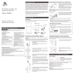
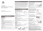
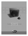
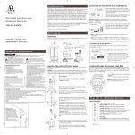
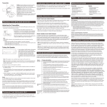
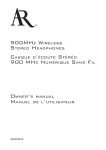
Wireless
Stereo Speakers
with auto-tuning
Model AW877
Installation and
Operation Manual
Important Information
CAUTION
RISK OF ELECTRIC SHOCK.
DO NOT OPEN.
Caution: To reduce the risk of electric shock, do not remove cover (or
back). No user serviceable parts inside. Refer servicing to qualified service
personnel.
WARNING: To reduce the risk of fire or electric
shock, do not expose this product to rain or
moisture. The apparatus shall not be exposed to
dripping or splashing. No objects filled with liquids,
such as vases, shall be placed on the apparatus.
FCC Statement
This equipment has been tested and found to
comply with the limits for a Class B digital device,
pursuant to part 15 of the FCC Rules. These limits
are designed to provide reasonable protection
against harmful interference in a residential
installation. This equipment generates, uses,
and can radiate radio frequency energy and, if
not installed and used in accordance with the
instructions, may cause harmful interference
to radio communication. However, there is no
guarantee that interference will not occur in a
particular installation. If this equipment does
cause harmful interference to radio or television
reception, which can be determined by turning
the equipment off and on, the user is encouraged
to try to correct the interference by one or more
of the following measures:
• Reorient or relocate the receiving antenna.
• Increase the separation between the
equipment and receiver.
• Connect the equipment into an outlet on
a circuit different from that to which the
receiver is connected.
• Consult the dealer or an experienced radio/
TV technician for help.
FCC Regulations state that unauthorized changes
or modifications to this equipment may void the
user’s authority to operate it.
Product Information
Keep your sales receipt to obtain warranty parts
and service and for proof of purchase. Attach it
here and record the serial and model numbers
in case you need them. These numbers are
located on the product.
Model No.:_ _______________________________
Purchase Date:_ ____________________________
Dealer/Address/Phone:______________________
Important Safety Instructions
1. 2. 3. 4. 5. 6. 7. 8. 9. 10. 11. Read these instructions.
Keep these instructions.
Heed all warnings.
Follow all instructions.
Do not use this apparatus near water.
Clean only with dry cloth.
Do not block any ventilation openings.
Install in accordance with the manufacturer’s
instructions.
Do not install near any heat sources such as
radiators, heat registers, stoves, or other apparatus
(including amplifiers) that produce heat.
Protect the power cord from being walked on
or pinched particularly at plugs, convenience
receptacles, and the point where they exit
from the apparatus.
Unplug this apparatus during lightning storms
or when unused for long periods of time.
Refer all servicing to qualified service
personnel. Servicing is required when the
apparatus has been damaged in any way, such
as power-supply cord or plug is damaged,
liquid has been spilled or objects have fallen
into the apparatus, the apparatus has been
exposed to rain or moisture, does not operate
normally, or has been dropped.
Care and Maintenance
• Always use a soft cloth to clean the speakers
and transmitter. Never use any product
containing alcohol or other solvents as they may
damage the surface.
• Use caution when plugging the power
transformers in an AC outlet to avoid the risk of
electric shock.
• Never expose the speakers or transmitter to rain
or moisture as this may cause damage. If the
speakers are used outside on a deck or patio,
make sure you take them indoors in the event of
a rainstorm to prevent possible damage.
• Do not operate or store the system in extreme
temperatures (below 32ºF/0ºC and above
122ºF/50ºC).
Table of Contents
Introduction........................................................................................1
Tour of the Speaker System..............................................................2
Connecting the Speaker System.......................................................4
Adjusting the Transmitter.................................................................6
Tuning the Speakers...........................................................................6
Turning the Speakers Off..................................................................7
More Helpful Information................................................................8
Troubleshooting..................................................................................9
Specifications....................................................................................10
12 Month Limited Warranty...........................................................10
Introduction
AR’s Wireless Stereo Speakers eliminate the hardest part of adding speakers
to your home—running and hiding hundreds of feet of speaker wire. The
AR Wireless Speaker System’s RF signal travels with ease through walls,
floors, ceilings and other obstacles, delivering high-quality sound virtually
anywhere inside the house or out. With drift- and static-free reception along
with outstanding range—up to 250 feet*—the possibilities for enjoying your AR
Wireless Speaker System are nearly unlimited. The AR Wireless Speaker System
is compatible with most audio sources, such as TVs, DVD players, VCRs, A/V
receivers/amps, stereos, computers, and portable devices (CD players, cassette
players, MP3s etc.).
This manual covers various connection options and detailed operating
instructions for making the AR Wireless Stereo Speakers a valued part of your
lifestyle. If, after having reviewed the instructions, you have any questions, please
call toll-free 1-800-732-6866 or visit www.araccessories.com.
*Range may vary according to environment.
Tour of the Speaker System
Speaker Front View
Power/Volume/Scan control turns the
speaker on, adjusts the volume level and
rescans for the transmitter’s signal; press and
hold to turn the speaker off
CHRG. indicator lights red when
the speaker is turned off and
rechargeable batteries are loaded
STDBY./TUNED indicator lights red when the
speaker is first powered on; it turns blue when
the speaker is tuned to the transmitter
Speaker Back View
Carrying handle
Battery Compartment Cover—
remove to install 8 C-cell batteries
L/Mono/R switch determines if
the speaker plays the left or right
track in a stereo pair, or plays
sound in mono as a stand-alone
speaker
Speaker power input jack receives the small round end
of one of the included 18V 700mA AC power adapters
Transmitter Front View
Transmission indicator lights blue when the audio is
present and the transmitter is broadcasting
Transmitter Back View
Channel select switch lets you find the best
transmission frequency for your environment
Built-in audio input cable connects to your
sound source using one of the connection
options shown on the next pages
Transmitter power input jack receives the small round
end of the included 12V 100mA AC power adapter
Included Accessories
/4” headphone
adapter (3.5mm to
6.3mm)
1
“Y” adapter cable
Speaker AC/DC 18V
700mA adapter (x2)
Transmitter
AC/DC 12V
100mA
adapter
Note: The power units
are intended to be
correctly oriented in a
vertical or floor mount
position.
Connecting the Speaker System
Powering the Transmitter
Connect the small, round plug from the transmitter AC power adapter to the
transmitter’s power input jack. Plug the other end of the transmitter AC power
adapter into any standard 120V AC wall outlet.
Note: Be sure to use the AC power adapter rated
12V DC 100 mA.
Transmitter
120V AC
wall outlet
AC Power
Adapter
Note: There is no transmitter ON/OFF switch.
The transmitter is designed to be left plugged in
and powered at all times. If you will not be using
the AW877 for an extended period of time, unplug
the transmitter AC power adapter.
Connecting to an Audio Source
Connecting to an A/V Receiver
Transmitter
A/V Receiver
Audio Output
“Y” adapter cable
Audio Input Cable
Connecting to a TV
TV
Transmitter
Audio Output
“Y” adapter cable
Audio Input Cable
1.Connect the included “Y” adapter cable to
the 3.5mm mini-plug cable coming out of
the transmitter.
2. Connect the left (white) and right (red)
audio plugs on the ”Y” adapter cable to the
corresponding left and right audio outputs of
your A/V receiver, amp or other audio source.
1.Connect the included “Y” adapter cable to
the 3.5mm mini-plug cable coming out of
the transmitter.
2.Connect the left (white) and right (red)
audio plugs on the “Y” adapter cable to the
corresponding left and right audio outputs
on the TV.
Connecting to a Stereo or Computer
Transmitter
Stereo
Audio Input Cable
1/4” headphone
adapter
Plug the cable coming out of the transmitter
into the headphone output of your stereo or the
audio output jack on your computer. Use the
included 1/4” headphone adapter to convert the
3.5mm plug to a 1/4” plug as needed.
Warning: This product is designed to work with line level outputs or headphone outputs
only. DO NOT connect it directly to speaker outputs as it will permanently damage the
transmitter.
Powering the Speakers
There are two options to power your wireless speakers: using the included AC
power adapters or using 8 C-cell batteries per speaker (not included).
AC Power Adapters
1. Turn the speaker volume down by rotating
the Power/Volume/Scan control on the
front of the speaker all the way to the left.
Speaker
AC Power
adapter
120 V AC
Wall Outlet
2.Insert the small, round plug from the
speaker AC power adapter into the speaker
power input jack.
3.Plug the other end of the speaker AC power adapter into any standard 120V AC
wall outlet.
Note: Be sure to use the speaker AC power adapter rated 18V DC 700 mA.
Warning: This product is not water resistant. To avoid electrical shock, it should not be
used near water sources if powered with the AC adapter. Never submerge in water.
C-cell Batteries
1.Turn the speaker volume down by rotating the Power/Volume/Scan control on the front of the speaker all the way to the left.
2. Remove the battery compartment cover on the back of the speaker.
3. Insert eight (8) C-cell batteries (not included) into the speaker following the
polarity (”+” and “-”) as diagrammed inside the battery compartment.
4.Replace the battery compartment cover on the back of the speaker.
Important: If you are using rechargeable batteries NiMH or NiCd, the batteries will
charge when the speaker is powered with the AC power adapter. DO NOT power the
speaker with the AC power adapter if you installed alkaline or other non-rechargeable
batteries – this could cause the batteries to leak, which would damage the speaker.
DO NOT mix batteries with different chemistry types (for example, a zinc battery with an
alkaline battery). DO NOT mix new and used batteries. DO NOT leave batteries installed in
the product when not in use for long periods. Always remove old, weak or worn-out batteries
promptly and recycle or dispose of them in accordance with local and national regulations.
Adjusting the Transmitter
1. Turn on your audio source (for example, A/V receiver, TV, stereo, etc.) and play
music at a normal listening volume.
Transmitter Back View
Built-in audio
input cable
Transmitter power
input jack
2. Set the channel select switch on the back of the
transmitter to one of the transmitter’s three
broadcast frequencies: 1, 2 or 3. If you experience
poor reception or interference, try choosing a
different frequency by moving the channel select
switch to another position.
Channel
select switch
Transmitter Front View
When the transmitter is receiving an audio signal
and is ready, the light on its front turns blue.
Note
If the light on the front of the transmitter does not turn
on, please check the following:
Transmission Indicator Light
- Confirm the transmitter AC power adapter is
securely connected.
- Confirm the cable from the transmitter is securely
connected to the audio source output (TV, A/V
receiver, etc.).
Tuning the Speakers
Standby/
Tuned
Indicator
Power/Tuning/
Volume Control
Speaker Front View
1.Press the Power/Volume/Scan control on each
speaker to turn it on. The STDBY./TUNED light
illuminates red while the speaker is tuning to the
transmitter. The STDBY./TUNED light turns blue
when the speaker is tuned to the transmitter—you
should hear sound coming from the speaker now.
Note: If the speaker is not tuned or if the transmitter is
not connected properly, the STDBY./TUNED indicator
will not turn from red to blue. If this occurs, please see
the troubleshooting section of this manual.
2. Adjust the volume on each speaker as desired.
3. Set up each speaker for mono or stereo operation.
Speaker Power
Input Jack
Left/Mono/Right
Slide Switch
Speaker Back View
a) Monaural operation: The monaural mode
(MONO) is recommended when using single
speakers separately. For monaural operation, set
the L/MONO/R switch to “MONO” on each
speaker.
b) Stereo operation: Set the L/MONO/R switch
to “L” on the speaker located to the left from
the listener, and set the other speaker to the “R”
position.
Notes:
Each speaker automatically retunes if it loses the
transmitter’s signal. You can also press the Power/
Volume/Scan button on the front of the speaker to
retune the speaker at any time.
The transmitter turns off automatically if there is no
audio signal present for a prolonged period.
Interference in the form of static and/or distortion
can sometimes be heard. If this occurs, confirm the
transmitter/speaker adjustments and indicators. If the
problem persists, refer to the Troubleshooting section of
this manual.
Turning the Speakers Off
1.Press and hold the Power/Volume / Scan control to turn the speaker off.
2.Confirm that the speaker is off by verifying that the STDBY./TUNED indicator
is no longer illuminated.
The speaker will automatically charge rechargeable batteries (NiMH or NiCd
only) when the batteries are installed and the speaker is plugged in with the AC
power adapter. The CHRG. indicator on the front of the speaker will illuminate.
Warning: DO NOT power the speaker with the AC power adapter if you installed
alkaline or other non-rechargeable batteries – this could cause the batteries to leak,
which would damage the speaker.
More Helpful Information
About Fixed-Level Audio Outputs
A fixed-level, or line-level audio output is considered ideal since it provides an
audio signal unchanged by adjustments to the audio source volume control.
Hint: Fixed-level audio outputs from stereo receivers/amps will typically be designated
as Tape, Tape 1, and Tape 2 outputs, or VCR audio output connections These outputs are
frequently marked on A/V equipment as ‘TAPE OUTPUT,’ ‘TAPE OUT,’ ‘TAPE REC,
or ‘TAPE RECORD or REC OUT.’
Please note: Jacks labeled PHONO, CD, LD, DVD or tape or VCR playback (PB) are
INPUTS and will not work with the transmitter.
Fixed-level outputs from TVs are usually marked as ‘Constant,’ ‘Fixed,’ or ‘Select.’ If
they are not marked as such, they are probably variable outputs (see “About VariableLevel Audio Outputs” on the next page). Outputs from VCRs are almost always fixed.
Hint: When connecting to the audio outputs of a VCR, remember that the VCR must be
playing a tape or showing a TV channel for sound to be produced.
Hint: If your VCR (or other audio source with RCA jacks) only has a single audio
output, you will need another RCA “Y” cable. It differs from the “Y” Cable Adapter
included with this speaker. It will have a single male RCA plug and 2 female RCA jacks.
Connect the dual RCA plugs from the included “Y” cable adapter to the 2 female RCA
jacks on the second “Y” cable, and then connect the single male RCA plug of the second
“Y” cable to the single audio output of the VCR.
About Variable-Level Audio Outputs:
A variable-level output, such as a headphone jack or certain RCA-type outputs,
provides an audio signal that changes with the volume level set on the audio
source. As the volume of the audio source is adjusted up and down, so is the
audio signal strength sent to the transmitter. This can affect the quality of sound
generated by the speaker, and may require an adjustment of the volume level of
the audio source to produce a signal strong enough for the transmitter.
Hint: On most bookshelf-type or compact stereo systems, inserting a headphone plug
into the headphone jack results in automatic cutoff of the regular, or hard-wired speakers.
Hint: Most TVs, regardless of age or price, have variable outputs. If you are unsure
which of your TV audio outputs is fixed, refer to the TV instruction manual. Some TVs
have outputs that can switch between variable and fixed. When given a choice, fixed is
always recommended.
Troubleshooting
The following troubleshooting guide takes you through some of the more common
problems associated with the installation and/or operation of a wireless system. If the
problem persists, please call toll-free at 1-800- 732-6866 or visit www.araccessories.com.
Issue:
Cause and solution:
No sound
• Check that the transmitter AC power adapter is fully inserted into the wall outlet
and the power cord from the AC adapter is firmly connected to the transmitter
power input jack.
• Confirm that the speakers are turned on and tuned to the transmitter—
the STDBY./TUNED indicator light on the front of each speaker should be
illuminated blue.
• If you’re using the power adapters, confirm that all three (for both speakers
and for the transmitter) are fully inserted into their wall outlets and the adapter
power cords are firmly connected to the power input jacks on the transmitter or
speaker.
or
• If you’re using batteries, check that they are fresh and inserted with correct
polarity (+, –).
• Check that the audio source component (stereo, TV, etc.) is turned on and
transmitting sound as it normally should.
• Check that the speaker volumes are turned up.
• If you are using a Tape 2 Monitor output from your receiver/amp as the audio
output, check that you have pressed the Tape Monitor/Tape 2 button on the
front of the receiver. This will turn on the Tape 2 outputs, which may not have
been active.
Issue:
Cause and solution:
No sound/
distortion/
static
• When using battery power, make sure the batteries are fresh and replace if
necessary.
• Check that the speaker STDBY./TUNED indicator is illuminated blue.
• Change the position of the channel select switch (1, 2 or 3) to change the
operating frequency. The speaker will detect the loss of signal and retune
automatically. You can also press the Power/Volume/Tuning control once to
make the speaker retune.
• Change the location of the transmitter. Place it as high and away from
obstructions as possible. Avoid placing the transmitter directly on top of or
behind a TV.
• Move the transmitter and speaker closer together. Sending the signal through
certain materials, such as glass, tile, and metal, can decrease the effective
transmitting distance of the system.
Specifications
Transmitter
Speaker
• Omni-directional 900MHz broadcast
• Effective transmitting range:
up to 250 ft. (80m)*
• Phase-locked loop circuitry (PLL)
• Automatic level control (ALC)
• 3 selectable broadcast frequencies
• Stereo audio input
• Push-button, auto-lock tuning
• 2-way acoustic design:
2” dome tweeter, 5” woofer
• 7.5 Watt RMS internal amplifier
(each speaker)
• Frequency response: 20Hz - 20kHz
• Left/Mono/Right switch
• Operates using supplied AC adapters or eight
(8) C-cell batteries (each speaker, not included)
• Dimensions: 10”H x 6 1/4””W x 7”D
• Dimensions: 4”H x 4 3/4”W x 2 3/4”D
*Maximum range; results may vary according to
environment.
12 Month Limited Warranty
Audiovox Electronics Corporation (the “Company”) warrants to the original retail purchaser of this
product that should this product or any part thereof, under normal use and conditions, be proven defective
in material or workmanship within 12 months from the date of original purchase, such defect(s) will be
repaired or replaced (at the Company’s option) without charge for parts and repair labor. To obtain repair
or replacement within the terms of this Warranty, the product along with any accessories included in the
original packaging is to be delivered with proof of warranty coverage (e.g. dated bill of sale), specification of
defect(s), transportation prepaid, to the Company at the address shown below. Do not return this product to
the Retailer.
This Warranty is not transferable and does not cover product purchased, serviced or used outside the
United States or Canada. The warranty does not extend to the elimination of externally generated static or
noise, to costs incurred for the installation, removal or reinstallation of the product.
The warranty does not apply to any product or part thereof which, in the opinion of the company, has
suffered or been damaged through alteration, improper installation, mishandling, misuse, neglect, accident
or exposure to moisture. This warranty does not apply to damage caused by an AC adapter not provided
with the product, or by leaving non-rechargeable batteries in the product while plugged into an AC outlet.
THE EXTENT OF THE COMPANY’S LIABILITY UNDER THIS WARRANTY IS LIMITED TO THE
REPAIR OR REPLACEMENT PROVIDED ABOVE AND, IN NO EVENT, SHALL THE COMPANY’S
LIABILITY EXCEED THE PURCHASE PRICE PAID BY PURCHASER FOR THE PRODUCT.
This Warranty is in lieu of all other express warranties or liabilities. ANY IMPLIED WARRANTIES,
INCLUDING ANY IMPLIED WARRANTY OF MERCHANTABILITY OR FITNESS FOR A PARTICULAR
PURPOSE, SHALL BE LIMITED TO DURATION OF THIS WARRANTY. ANY ACTION FOR BREACH
OF ANY WARRANTY HEREUNDER, INCLUDING ANY IMPLIED WARRANTY, MUST BE BROUGHT
WITHIN A PERIOD OF 24 MONTHS FROM THE DATE OF ORIGINAL PURCHASE. IN NO CASE
SHALL THE COMPANY BE LIABLE FOR ANY CONSEQUENTIAL OR INCIDENTAL DAMAGES
WHATSOEVER. No person or representative is authorized to assume for the Company any liability other
than expressed herein in connection with the sale of this product.
Some states/provinces do not allow limitations on how long an implied warranty lasts or the exclusion
or limitation of incidental or consequential damage so the above limitations or exclusions may not apply
to you. This Warranty gives you specific legal rights and you may also have other rights which vary from
state/province to state/province.
U.S.A.:Audiovox Electronics Corp., 150 Marcus Blvd., Hauppauge, New York 11788
CANADA: Audiovox Return Center, c/o Genco, 6685 Kennedy Road, Unit 3, Door 16,
Mississauga Ontario L5T 3A5
©2007 AEC, 150 Marcus Blvd. Hauppauge, NY 11788
Trademark(s) ® Registered
www.araccessories.com
MADE IN CHINA
AW877 US IB 01
Addendum to the Installation Manual
Accessing the Speaker Battery Compartments
There are two options to power your wireless speakers: using the included
AC power adapters or using 8 C-cell batteries per speaker (not included). The
Installation and Operation Manual takes you through the steps to do both on page 5.
The Installation and Operation Manual does not include instructions for accessing
the battery compartment on each speaker.
Speaker Back
To remove a speaker battery compartment cover:
1. Lay the speaker gently on its front.
2. Use a Phillips-head screwdriver to loosen the
compartment cover screws.
3. Hold the battery compartment cover and turn
the speaker over. The screws should fall out.
If they don’t, lay the speaker on its front again
and loosen the screws a little more.
Cover
Screws
Important: Don’t lose the screws! You’ll need
them to put the battery compartment cover
back on.
4. Put the speaker on its front again. Remove the
battery compartment cover.
5.Insert eight (8) C-cell batteries (not included)
in the speaker following the polarity (+ and –)
diagram inside the compartment.
Speaker Battery
Compartment Cover
To replace the speaker battery compartment cover:
1. Put the battery compartment back in place.
2. Put the screws back in the holes on the battery compartment cover. Use a
Phillips-head screwdriver to tighten the compartment cover screws.
AW877_TIS2_00