1
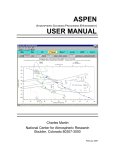
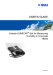
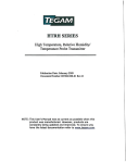
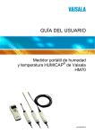
USER'S GUIDE
Calibration of Series HMD/W60/70 and
HMP140 Transmitters with
Vaisala HUMICAP® Indicator HMI41
U218EN11
PUBLISHED BY
Vaisala Oyj
P.O. Box 26
FIN-00421 Helsinki
Finland
Phone (int.): +358 9 8949 1
Fax:
+358 9 8949 2227
Visit our Internet pages at http://www.vaisala.com/
© Vaisala 2006
No part of this manual may be reproduced in any form or by any means, electronic or
mechanical (including photocopying), nor may its contents be communicated to a third
party without prior written permission of the copyright holder.
The contents are subject to change without prior notice.
Please observe that this manual does not create any legally binding obligations for
Vaisala towards the customer or end user. All legally binding commitments and
agreements are included exclusively in the applicable supply contract or Conditions of
Sale.
HMI41 Calibration Option
Operating Manual
19116ZZ-U218en-1.1
Contents
1. INTRODUCTION ...................................................................................................................... 1
1.1 HMI41 with calibration option ...................................................................................... 1
1.2 Selecting the HMI41 calibrator function ...................................................................... 1
2. OUTPUT SCALE SELECTIONS............................................................................................... 3
2.1 Standard transmitter settings ............................................................................... 3
2.2 Getting started .............................................................................................................. 3
2.3 Scale selection modes .................................................................................................. 4
2.3.1 Voltage output selection mode (U) ................................................................... 4
2.3.2 Current output selection mode (I)..................................................................... 5
2.3.3 Customized voltage output selection mode (cU) .............................................. 6
2.3.3.1 Humidity channel ........................................................................................... 7
2.3.3.2 Temperature channel..................................................................................... 9
2.3.4 Customized current output selection mode (cI) .............................................. 10
2.3.4.1 Humidity channel ......................................................................................... 11
2.3.4.2 Temperature channel................................................................................... 12
3. CALIBRATION ....................................................................................................................... 13
3.1 Getting started ............................................................................................................ 13
3.2 Humidity calibration.................................................................................................... 15
3.3 Temperature calibration ............................................................................................. 16
APPENDIX 1: QUICK REFERENCE TO SCALE SELECTIONS AND CALIBRATION
1996-08-29
i
HMI41 Calibration Option
Operating Manual
19116ZZ-U218en-1.1
This page intentionally left blank.
ii
1996-08-29
HMI41 Calibration Option
Operating Manual
19116ZZ-U218en-1.1
1.
INTRODUCTION
1.1
HMI41 with calibration option
The HMI41 can be used as a field calibrator for various Vaisala humidity
transmitters. There are three different calibration cables available:
• 19116ZZ
for the calibration of HMD/W60/70 and HMP140
series analogue transmitters
• 19164ZZ
for the calibration of HMP230 series digital
transmitters
• 19165ZZ
for the calibration of the HMD/W20/30 and
HMP130 series analogue transmitters
In this manual, only the calibration of the HMD/W60/70 and HMP140 series
analogue transmitters is dealt with. For other calibration options, please refer
to corresponding manuals.
Calibration is quick and easy to perform. Yet, the HMI41 includes four output
scale selection modes which cover all scalable features of analogue
transmitters and provide for a simple and reliable on-site calibration of even
customized transmitters. In calibration, the HMI41 measures relative humidity
and temperature with a separate probe, and receives the RH and T information
from the transmitter. These values are then compared on the HMI41 display
and the transmitter is adjusted with calibration potentiometers inside the
transmitter.
1.2
Selecting the HMI41 calibrator function
The desired calibrator function is selected in the HMI41 setup menu. To enter
the setup mode, first press the ON/OFF button and the following appears:
RH
%
Td
°C °F
T
°C °F
P
g/m hPa
setminmax hyst hold Lo batHi
Then release the ON/OFF button and within 1...2 seconds press both ENTER
and MODE buttons until the following text appears on the display:
After a few seconds, the text changes automatically to show the following:
1996-08-29
1
HMI41 Calibration Option
Operating Manual
19116ZZ-U218en-1.1
°C
set
If the basic settings of the HMI41 (display units, automatic power off
function, display quantities and pressure) have to be changed, please refer to
the HMI41 Operating Manual. Otherwise, press ENTER repeatedly until the
following text appears:
set
The number on the first line of the display corresponds to the following
HMI41 functions:
1 = HMI41 as a humidity and temperature indicator
2 = HMI41 as a calibrator for HMD/W60/70 and HMP140 series analogue
transmitters
3 = HMI41 as a calibrator for HMP230 series digital transmitters
4 = HMI41 as a calibrator for the HMD/W20/30 and HMP130 series
analogue transmitters
To calibrate the HMD/W60/70 or the HMP140 series transmitters, select
number 2 with buttons ▲ (number up) and ▼ (number down) and then turn
the HMI41 off. When the HMI41 is turned on again, it will automatically
wake up as a calibrator for these analogue transmitters. If you wish to calibrate
transmitters of some other type or use the HMI41 as an indicator, this
selection has to be done accordingly; refer to corresponding manuals for
further details.
Note that if the default settings in the HMI41 memory have not been changed
(e.g. when it is used as a calibrator for the first time), the HMP140 series
transmitters with standard settings and voltage outputs can be directly
calibrated (see Chapter 3). In all other cases scale selections are necessary;
please, consult Chapter 2. The default settings in the HMI41 memory (Table
1.2) are returned with U, I, cU or cI selections according to which changes
have been made.
Humidity range
0...100 %RH
Temperature range
-40...+60 °C
Voltage range
0...1V
0...5V
0...10V
Table 1.2 Default settings in the HMI41 memory
2
1996-08-29
HMI41 Calibration Option
Operating Manual
19116ZZ-U218en-1.1
2.
OUTPUT SCALE SELECTIONS
2.1 Standard transmitter settings
In Table 2.1 you will find the standard settings of the HMD/W60, HMD/W70
and the HMP140 series transmitters.
Transmitter Relative humidity
scaling range
Temperature
scaling range
HMP140
0...100 %RH
-40...+60 °C
HMD60
0...100 %RH
-20...+80 °C
HMD70
0...100 %RH
-20...+80 °C
HMW60
0...100 %RH
-5...+55 °C
0...100 %RH
HMW70
Table 2.1
-5...+55 °C
Voltage
output
0...1 V
0...5 V
0...10 V
Current output
0...20 mA
4...20 mA
0...1 V
0...5 V
0...10 V
0...20 mA
4...20 mA
0...1 V
0...5 V
0...10 V
Standard settings of analogue transmitters
NOTE
When calibrating transmitters with current outputs,
make sure that the output loop is terminated.
2.2
Getting started
After having selected the calibrator function 2 as explained in Chapter 1.2,
turn the HMI41 on with the ON/OFF button and wait until the following text
appears on the display:
RH
T
This message remains on the display for about 5 seconds; if no button is
pressed, the HMI41 goes on to calibration. To enter the scale selections, press
any button (except ON/OFF) within 5 seconds and the following appears:
1996-08-29
3
HMI41 Calibration Option
Operating Manual
19116ZZ-U218en-1.1
Scale selection mode is entered when this text is on the display.
2.3
Scale selection modes
The HMI41 has four scale selection modes: voltage output (U) and current
output (I) selection modes are used for transmitters with standard settings.
Customized voltage output (cU) and customized current output (cI) selection
modes are meant for analogue transmitters with customized RH, T and/or
output range settings. All these selections are stored in the HMI41 memory;
therefore, if the transmitter settings or the selections in the HMI41 memory
have not been changed by the next calibration, you can calibrate the
transmitter directly. In the following, each selection mode is explained in its
own section.
2.3.1
Voltage output selection mode (U)
If the transmitter has voltage outputs, its temperature range is given to the
HMI41 with the voltage output selection mode (U). The humidity range is
always 0...100 %RH. Select the U selection mode with buttons ▲ or ▼ and
acknowledge the selection with ENTER. A text similar to the following is
displayed:
T
°C
T
°C
set
Lo
Numbers on the second line are blinking. They indicate the lower limit of the
transmitter’s temperature range currently stored in the HMI41 memory. Text
in the lower righthand corner is Lo. You can now set the lower limit with
buttons ▲ (number up) or ▼ (number down) to correspond to that of the
transmitter. Acknowledge the setting with ENTER:
4
1996-08-29
HMI41 Calibration Option
Operating Manual
19116ZZ-U218en-1.1
T
°C
T
°C
set
Hi
Numbers on the first line start to blink. They indicate the upper limit of the
transmitter’s temperature range currently stored in the HMI41 memory. Text
in the lower righthand corner is Hi. You can now set the upper limit with
buttons ▲ (number up) or ▼ (number down) to correspond to that of the
transmitter. Acknowledge the setting with ENTER and turn the HMI41 off
with the ON/OFF button.You can now calibrate the transmitter (see Chapter
3).
2.3.2
Current output selection mode (I)
NOTE
When calibrating the transmitters with current outputs,
make sure that the output loop is terminated.
If the transmitter has current outputs, its temperature range is given to the
HMI41 with the current output selection mode (I). The RH range is always
0...100 %RH. Select the I selection mode with buttons ▲ or ▼ and
acknowledge the selection with ENTER. A text similar to the following is
displayed:
set
Numbers on the display are blinking, and you can now select the output (0...20
or 4...20 mA) with buttons ▲ or ▼ according to the transmitter to be
calibrated. Acknowledge the selection with ENTER and a text similar to the
following is displayed:
1996-08-29
5
HMI41 Calibration Option
Operating Manual
19116ZZ-U218en-1.1
T
°C
T
°C
set
Lo
Numbers on the second line are blinking. They indicate the lower limit of the
transmitter’s temperature range currently stored in the HMI41 memory. Text
in the lower righthand corner is Lo. You can now set the lower limit with
buttons ▲ (number up) or ▼ (number down) to correspond to that of the
transmitter. Acknowledge the setting with ENTER:
T
°C
T
°C
set
Hi
Numbers on the first line start to blink. They indicate the upper limit of the
transmitter’s temperature range currently stored in the HMI41 memory. Text
in the lower righthand corner is Hi. You can now set the upper limit with
buttons ▲ (number up) or ▼ (number down) to correspond to that of the
transmitter. Acknowledge the setting with ENTER and turn the HMI41 off
with the ON/OFF button. You can now calibrate the transmitter (see Chapter
3).
2.3.3
Customized voltage output selection mode (cU)
The customized voltage output selection mode (cU) is selected when the
scaling of the RH, T and/or voltage range is not a standard one.
Select the cU selection mode with buttons ▲ or ▼ and acknowledge the
selection with ENTER. A text similar to the following is displayed:
RH
set
6
1996-08-29
HMI41 Calibration Option
Operating Manual
19116ZZ-U218en-1.1
2.3.3.1
Humidity channel
RH
set
Numbers on the display are blinking. They indicate the voltage range of the
transmitter’s RH channel (jumper selectable) currently stored in the HMI41
memory. Please, consult Figures 2.3.1 - 2.3.2 when checking the transmitter’s
jumper positions.
RH output
selections
0...1V
0...5 V
0...10 V
Figure 2.3.1
Jumper selections of the HMD/W70
RH output
selections
0...1V 0...5 V
Figure 2.3.2
0...10 V
Jumper selections of the HMP140
Numbers on the second line are blinking, and you can now select the range
with buttons ▲ or ▼ according to the transmitter’s jumper position.
Acknowledge the selection with ENTER. A text similar to the following is
displayed:
RH
set
Lo
Numbers on the second line are blinking. They indicate the lower limit of the
transmitter’s voltage range currently stored in the HMI41 memory. Text in the
lower righthand corner is Lo. You can now set the lower limit of the voltage
range to correspond to that of the transmitter. Set the limit with buttons ▲ or
▼ and acknowledge the setting with ENTER:
1996-08-29
7
HMI41 Calibration Option
Operating Manual
19116ZZ-U218en-1.1
RH
set
Hi
Numbers on the first line start to blink. They indicate the upper limit of the
transmitter’s voltage range currently stored in the HMI41 memory and the text
in the lower righthand corner is Hi. You can now set the upper limit of the
voltage range to correspond to that of the transmitter. Set the limit with
buttons ▲ or ▼ and acknowledge the setting with ENTER. A text similar to
the following is displayed:
RH
set
%
Lo
Numbers on the second line are blinking. They indicate the lower limit of the
transmitter’s RH range currently stored in the HMI41 memory. Text in the
lower righthand corner is Lo. You can now set the lower limit of the RH range
to correspond to that of the transmitter. Set the limit with buttons ▲ or ▼ and
acknowledge the setting with ENTER:
RH
set
%
Hi
Numbers on the first line start to blink. They indicate the upper limit of the
transmitter’s RH range currently stored in the HMI41 memory. Text in the
lower righthand corner is Hi. You can now set the upper limit of the RH range
to correspond to that of the transmitter. Set the limit with buttons ▲ or ▼ and
acknowledge the setting with ENTER. The HMI41 goes on to T channel
settings, and a text similar to the following is displayed:
T
set
8
1996-08-29
HMI41 Calibration Option
Operating Manual
19116ZZ-U218en-1.1
2.3.3.2
Temperature channel
T
set
Numbers on the second line are blinking. They indicate the voltage range of
the transmitter’s T channel (jumper selectable) currently stored in the HMI41
memory. Please, consult Figures 2.3.3 - 2.3.4 when checking the transmitter’s
jumper positions.
T output
selections
0...1V
0...5 V
0...10 V
Figure 2.3.3
Jumper selections for the HMD/W70
T output
selections
0...1V
0...5 V
0...10 V
Figure 2.3.4
Jumper selections for the HMP140
You can now set the range with buttons ▲ or ▼ to correspond to the jumper
position. Acknowledge the setting with ENTER. A text similar to the
following is displayed:
T
set
Lo
Numbers on the second line are blinking. They indicate the lower limit of the
transmitter’s voltage range currently stored in the HMI41 memory. Text in the
lower righthand corner is Lo. You can now set the lower limit with buttons ▲
or ▼ to correspond to that of the transmitter. Acknowledge the selection with
ENTER. A text similar to the following is displayed:
1996-08-29
9
HMI41 Calibration Option
Operating Manual
19116ZZ-U218en-1.1
T
set
Hi
Numbers on the first line start to blink. They indicate the upper limit of the
transmitter’s voltage range currently stored in the HMI41 memory. Text in the
lower righthand corner is Hi. You can now set the upper limit with buttons ▲
or ▼ to correspond to that of the transmitter. Acknowledge the setting with
ENTER. A text similar to the following is displayed:
T
°C
T
°C
set
Lo
Numbers on the second line are blinking. They indicate the lower limit of the
transmitter’s temperature range currently stored in the HMI41 memory. Text
in the lower righthand corner is Lo. You can now set the lower limit to
correspond to that of the transmitter. Set the limit with buttons ▲ or ▼ and
acknowledge the setting with ENTER:
T
°C
T
°C
set
Hi
Numbers on the first line start to blink. They indicate the upper limit of the
transmitter’s temperature range currently stored in the HMI41 memory. Text
in the lower righthand corner is Hi. You can now set the upper limit to
correspond to that of the transmitter. Set the limit with buttons ▲ or ▼ and
acknowledge the setting with ENTER. Turn the HMI41 off with the ON/OFF
button. You can now calibrate the transmitter (see Chapter 3).
2.3.4
Customized current output selection mode (cI)
The customized current output selection mode (cI) is selected when the scaling
of the RH, T and/or current range is not a standard one.
NOTE
When calibrating transmitters with current outputs,
make sure that the output loop is terminated.
10
1996-08-29
HMI41 Calibration Option
Operating Manual
19116ZZ-U218en-1.1
Select the cI selection mode with buttons ▲ or ▼ and acknowledge the
selection with ENTER. A text similar to the following is displayed:
RH
set
2.3.4.1
Humidity channel
RH
set
Numbers on the second line are blinking. They indicate the current range of
the the transmitter’s RH channel currently stored in the HMI41 memory.
Select the range with buttons ▲ or ▼ to correspond to that of the transmitter.
Acknowledge the selection with ENTER. A text similar to the following is
displayed:
RH
set
%
Lo
Numbers on the second line are blinking. They indicate the lower limit of the
transmitter’s RH range currently stored in the HMI41 memory. Text in the
lower righthand corner is Lo. You can now set the lower limit to correspond to
that of the transmitter. Set the limit with buttons ▲ or ▼ and acknowledge the
setting with ENTER:
RH
set
%
Hi
Numbers on the first line start to blink. They indicate the upper limit of the
transmitter’s RH range currently stored in the HMI41 memory. Text in the
1996-08-29
11
HMI41 Calibration Option
Operating Manual
19116ZZ-U218en-1.1
lower righthand corner is Hi. You can now set the upper limit to correspond to
that of the transmitter. Set the limit with buttons ▲ or ▼ and acknowledge the
setting with ENTER. The HMI41 goes on to T channel settings and a text
similar to the following is displayed:
T
set
2.3.4.2
Temperature channel
T
set
Numbers on the second line are blinking. They indicate the current range of
the transmitter’s T channel currently stored in the HMI41 memory. Select the
range with buttons ▲ or ▼ to correspond to that of the transmitter.
Acknowledge the selection with ENTER. A text similar to the following is
displayed:
T
°C
T
°C
set
Lo
Numbers on the second line are blinking. They indicate the lower limit of the
transmitter’s temperature range currently stored in the HMI41 memory. Text
in the lower righthand corner is Lo. You can now set the lower limit to
correspond to that of the transmitter. Set the limit with buttons ▲ or ▼ and
acknowledge the setting with ENTER:
T
°C
T
°C
set
Hi
Numbers on the first line start to blink. They indicate the upper limit of the
transmitter’s temperature range currently stored in the HMI41 memory. Text
in the lower righthand corner is Hi. You can now set the upper limit to
correspond to that of the transmitter. Set the limit with buttons ▲ or ▼ and
acknowledge the setting with ENTER. Turn the HMI41 off with the ON/OFF
button. You can now calibrate the transmitter (Chapter 3).
12
1996-08-29
HMI41 Calibration Option
Operating Manual
19116ZZ-U218en-1.1
3.
CALIBRATION
For a successful calibration, it is essential that the probe of the HMI41 and
that of the transmitter are at the same temperature, and that the reference
probe has been previously calibrated. Always allow enough time for the
readings to stabilize. Note that the stabilization time depends on the ambient
conditions and may vary from 10 minutes to a couple of hours.
3.1
Getting started
After having selected the desired function (Chapter 1.2) and necessary scale
selections (Chapter 2), turn the HMI41 off and connect the calibration cable to
the EXT connector at the bottom of the HMI41 (see Figure 3.1) and to the
appropriate connector in the transmitter (see Figures 3.2 - 3.4).
MO DE
HOLD
ENTER
ON/OFF
EXT
Connector for the
calibrati on cable
Figure 3.1
Location of the HMI41 calibration connector
TEST CONNECTOR
FOR CURRENT OUTPUTS
HMD60U/Y
HMD70U/Y
RH
TEST
1
TEST CONNECTOR
FOR VOLTAGE OUTPUTS
1
U
U
U
U
I-module 0-20mA
T
TEST
RH OFFSET
RH OFFSET
RH GAIN
T GAIN
T OFFSET
RH GAIN
T GAIN
Figure 3.2
1996-08-29
T OFFSET
Calibration connectors and potentiometers in
the HMD60 and HMD70 transmitters
13
HMI41 Calibration Option
Operating Manual
19116ZZ-U218en-1.1
RH TEST
X3
T TEST
X4
T GAIN
TEST
CONNECTOR
T OFFSET
RH
RH
OFFSET GAIN
RH
OFFSET
HMD70U/Y
HMW60U/Y
Figure 3.3
T GAIN T OFFSET
RH
GAIN
Calibration connectors and potentiometers in
the HMW60 and HMW70 transmitters
Tgain
Toffset
Test connector for
voltage outputs
RHoffset
Test connector for
current outputs
RHgain
Current Module
Figure 3.4
14
Calibration connectors and potentiometers in the
HMP140 series transmitters
1996-08-29
HMI41 Calibration Option
Operating Manual
19116ZZ-U218en-1.1
3.2
Humidity calibration
When performing the humidity calibration of the HMD/W60 transmitters,
make sure that the calibration cable is connected to the RH test connector
(Figures 3.2 and 3.3).
After having connected the cable, turn the HMI41 on with the ON/OFF button
and wait until the following text appears on the display:
RH
T
This message remains on the display for about 5 seconds. Press no button
when this text is displayed and the HMI41 will automatically go on to
calibration; a text similar to the following appears:
RH
%
Numbers on the first line indicate the relative humidity measured by the
transmitter, and numbers on the second line indicate the RH measured by the
HMI41 reference probe. If you wish, you can now adjust the transmitter:
• Wait until the readings have stabilized and adjust the calibration
potentiometers (Figures 3.2 - 3.4) until the readings on the first and
the second line are the same. It is recommended to use the offset
potentiometer if the RH is <65 %RH and the gain potentiometer if the
RH is >65 %RH.
• After having completed the calibration, press MODE if you wish to
perform a temperature calibration (see next page), or ON/OFF
(disconnect the cable).
If you press the HOLD button in the first RH calibration mode, you will go on
to the second RH calibration mode which is an alternative for the first one. A
text similar to the following is displayed:
RH
1996-08-29
%
15
HMI41 Calibration Option
Operating Manual
19116ZZ-U218en-1.1
Numbers on the first line indicate how much the RH measured by the
transmitter differs from that measured by the HMI41 reference probe.
Numbers on the second line indicate the relative humidity measured by the
reference probe. If you wish, you can now adjust the transmitter (by pressing
HOLD again you will return to the previous RH calibration mode):
• Wait until the readings have stabilized and adjust the calibration
potentiometers (Figures 3.2 - 3.4) until the numbers on the first line
are at zero. It is recommended to use the offset potentiometer if the
RH is <65 %RH and the gain potentiometer if the RH is >65 %RH.
• After having completed the calibration, press MODE if you wish to
perform a temperature calibration (see below), or ON/OFF
(disconnect the cable).
3.3
Temperature calibration
As the temperature sensor is extremely stable, temperature calibration should
be used for check-ups only. Before starting the temperature calibration, leave
the transmitter and the HMI41 to the same room at least for an hour so that
their temperatures have enough time to equalize. If the difference between the
readings is less than 0.5 °C, make no adjustments.
When performing the temperature calibration of the HMD/W60 transmitters,
make sure that the calibration cable is connected to the T test connector
(Figures 3.2 and 3.3).
Temperature calibration is entered through the RH calibration modes (see
Chapter 3.2). By pressing MODE in the first RH calibration mode, a text
similar to the following is displayed:
T
°C
T
°C
Numbers on the first line indicate the temperature measured by the transmitter,
and numbers on the second line indicate the temperature measured by the
HMI41. If you wish, you can now adjust the transmitter (by pressing the
MODE button you will return to the RH calibration mode):
• Wait until the readings have stabilized and then adjust the calibration
potentiometer (Figures 3.2 - 3.4) until the readings on the first and the
second line are the same. It is recommended to use the offset
potentiometer.
• After having completed the calibration, press ON/OFF and disconnect
the cable.
16
1996-08-29
HMI41 Calibration Option
Operating Manual
19116ZZ-U218en-1.1
If you press the HOLD button in the first T calibration mode, you will go on to
the second T calibration mode which is an alternative for the first one. A text
similar to the following is displayed:
T
°C
T
°C
Numbers on the first line indicate how much the temperature measured by the
transmitter differs from that measured by the HMI41 reference probe.
Numbers on the second line indicate the temperature measured by the
reference probe. If you wish, you can now adjust the transmitter (by pressing
the HOLD button again you will return to the previous T calibration mode and
by pressing the MODE button you will return to the second RH calibration
mode):
• Wait until the readings have stabilized and then adjust the calibration
potentiometer (Figures 3.2 - 3.4) until the numbers on the first line
are at zero. It is recommended to use the offset potentiometer.
• After having completed the calibration, press ON/OFF and disconnect
the cable.
GUARANTEE
Vaisala issues a guarantee for the material and workmanship of this product
under normal operating conditions for one (1) year from the date of delivery.
Exceptional operating conditions, damage due to careless handling and misapplication will void the guarantee.
1996-08-29
17
HMI41 Calibration Option
Appendix 1
19116ZZ-U218-1.1
APPENDIX 1: QUICK REFERENCE TO SCALE SELECTIONS AND
CALIBRATION
It is recommended that this quick reference guide is used only as a checking
list for those who already know how to operate the HMI41 as a calibrator. For
those who take it into use for the first time, the Operating Manual gives useful
information that is not included in this quick reference guide.
1.
Selecting the calibrator function
For selecting the calibrator function, press ON/OFF until you can see some
text on the display. Then release the ON/OFF button and press within 1...2
seconds both ENTER and MODE buttons until the text "setup" appears on the
display. Then follow the instructions of the table below.
DISPLAY
WHAT TO DO
PRESS:
Wait for a few seconds.
°C
set
set
1996-08-26
If the basic settings have been given,
press ENTER.
If they have not been given, refer to the
HMI41 Operating Manual.
select the HMI41 function:
1 = indicator
2 = calibrator for HMD/W60/70 and
HMP140 series analogue transmitters
3 = calibrator for HMP230 transmitters
4 = calibrator for HMD/W20/30 and
HMP130 series transmitters
press ENTER repeatedly:
▲ (number up) or
▼ (number down)
ON/OFF
1
HMI41 Calibration Option
Appendix 1
2.
19116ZZ-U218en-1.1
Scale selection modes
The HMI41 automatically assumes the function selected in the setup menu
when it is turned on again with the ON/OFF button. In the following, you will
find a summary of the scale selection modes.
DISPLAY
RH
%
Td
°C°F
T
°C°F
DESCRIPTION
The HMI41 has been turned on.
Pabs
g/m Pa
setminmax hyst hold Lo batHi
Indication of the software version (if the version
is 1.02 or more)
Indication of the battery voltage.
bat Hi
RH
T
Press any button except ON/OFF within 5
seconds to enter the scale selection modes.
Select the desired scale selection mode with
buttons ▲or ▼ and acknowledge the selection
with ENTER. Then follow the instructions of
tables 2.1 - 2.5 accordingly.
2.1
Voltage output scale selection mode (U)
DISPLAY
WHAT TO DO
Select the voltage output scale selection
mode (U)
T
°C
T
set
°C
Lo
T
°C
T
set
2
Set the lower limit of the temperature
range
°C
Hi
Set the upper limit of the temperature
range
PRESS:
▲ (number up) or
▼ (number down)
ENTER to acknowledge the
selection
▲ (number up) or
▼ (number down)
ENTER to acknowledge the
selection
▲ (number up) or
▼ (number down)
ENTER to acknowledge the
selection
ON/OFF
1996-08-26
HMI41 Calibration Option
Appendix 1
19116ZZ-U218-1.1
2.2
Current output scale selection mode (I)
DISPLAY
WHAT TO DO
Select the current output scale selection
mode (I)
Select the output
(0...20 mA or 4...20 mA)
set
T
°C
T
set
°C
Lo
T
°C
T
set
Set the lower limit of the temperature
range
°C
Hi
1996-08-26
Set the upper limit of the temperature
range
PRESS:
▲ (number up) or
▼ (number down)
ENTER to acknowledge the
selection
▲ (number up) or
▼ (number down)
ENTER to acknowledge the
selection
▲ (number up) or
▼ (number down)
ENTER to acknowledge the
selection
▲ (number up) or
▼ (number down)
ENTER to acknowledge the
selection
ON/OFF
3
HMI41 Calibration Option
Appendix 1
2.3
Customized voltage output selection mode (cU)
DISPLAY
WHAT TO DO
Select the customized voltage output
scale selection mode (cU)
RH
Select the jumper selected RH channel’s
voltage output range
(0...1V, 0...5V, 0...10V)
set
RH
set
Lo
Set the lower limit of the RH channel’s
voltage range
Hi
Set the upper limit of the RH channel’s
voltage range
RH
set
RH
%
Set the lower limit of the humidity range
set
Lo
RH
%
Set the upper limit of the humidity range
set
Hi
T
Select the jumper selected T channel’s
voltage output range
(0...1V, 0...5V, 0...10V)
set
Lo
Set the lower limit of the T channel’s
voltage range
Hi
Set the upper limit of the T channel’s
voltage range
T
set
T
set
T
°C
T
°C
set
Lo
T
°C
T
°C
set
4
19116ZZ-U218en-1.1
Hi
Set the lower limit of the temperature
range
Set the upper limit of the temperature
range
PRESS:
▲ (number up) or
▼ (number down)
ENTER to acknowledge the
selection
▲ (number up) or
▼ (number down)
ENTER to acknowledge the
selection
▲ (number up) or
▼ (number down)
ENTER to acknowledge the
selection
▲ (number up) or
▼ (number down)
ENTER to acknowledge the
selection
▲ (number up) or
▼ (number down)
ENTER to acknowledge the
selection
▲ (number up) or
▼ (number down)
ENTER to acknowledge the
selection
▲ (number up) or
▼ (number down)
ENTER to acknowledge the
selection
▲ (number up) or
▼ (number down)
ENTER to acknowledge the
selection
▲ (number up) or
▼ (number down)
ENTER to acknowledge the
selection
▲ (number up) or
▼ (number down)
ENTER to acknowledge the
selection
▲ (number up) or
▼ (number down)
ENTER to acknowledge the
selection
press ON/OFF
1996-08-26
HMI41 Calibration Option
Appendix 1
19116ZZ-U218-1.1
2.4
Customized current output selection mode (cI)
DISPLAY
WHAT TO DO
Select the customized current output scale
selection mode (cI)
Select the RH channel’s current output
range
(4...20 mA, 0...20 mA)
RH
set
RH
set
%
Lo
RH
set
%
Select the T channel’s current output
range
(4...20 mA, 0...20 mA)
set
T
°C
T
°C
Set the lower limit of the temperature
range
Lo
T
°C
T
set
Set the upper limit of the humidity range
Hi
T
set
Set the lower limit of the humidity range
°C
Hi
1996-08-26
Set the upper limit of the temperature
range
PRESS:
▲ (number up) or
▼ (number down)
ENTER to acknowledge the
selection
▲ (number up) or
▼ (number down)
ENTER to acknowledge the
selection
▲ (number up) or
▼ (number down)
ENTER to acknowledge the
selection
▲ (number up) or
▼ (number down)
ENTER to acknowledge the
selection
▲ (number up) or
▼ (number down)
ENTER to acknowledge the
selection
▲ (number up) or
▼ (number down)
ENTER to acknowledge the
selection
▲ (number up) or
▼ (number down)
ENTER to acknowledge the
selection
press ON/OFF
5
HMI41 Calibration Option
Appendix 1
2.5
19116ZZ-U218en-1.1
Calibration
DISPLAY
WHAT TO DO
PRESS:
Wait for about 5 seconds.
RH
T
RH
%
RH
%
T
°C
T
°C
T
°C
T
°C
6
Let the readings stabilize and then adjust
the transmitter potentiometers until the
readings are the same. Alternatively, you
can calibrate the transmitter in the second
RH calibration mode (see below).
Let the readings stabilize and then adjust
the transmitter potentiometers until the
reading on the first line is at zero
Let the readings stabilize and then adjust
the transmitter offset potentiometer until
the readings are the same. Alternatively,
you can calibrate the transmitter in the
second T calibration mode (see below).
Let the readings stabilize and then adjust
the transmitter offset potentiometer until
the reading on the first line is at zero.
HOLD to enter the second RH
calibration mode
MODE to enter the first T
calibration mode
ON/OFF if you have
completed the calibration
HOLD to return to the first
RH calibration mode
MODE to enter the second T
calibration mode
ON/OFF if you have
completed the calibration
HOLD to enter the second T
calibration mode
MODE to return to the first
RH calibration mode
ON/OFF if you have
completed the calibration
HOLD to return to the first T
calibration mode
MODE to return to the second
RH calibration mode
ON/OFF if you have
completed the calibration
1996-08-26
www.vaisala.com
*U218EN*