1
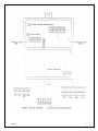
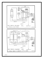
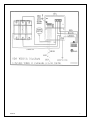
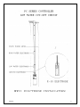
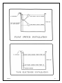
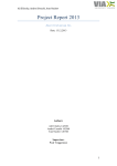
PVA 5-30
SDS SUBMERISIBLE
PUMP CONTROLLER
USER’S MANUAL
PVA5-30 PUMP CONTROLLER
12-30 VOLT STEP-UP
FOR CONTROLLERS WITH SERIAL NUMBERS 13630 AND ABOVE WITH OUTPUT OVER-VOLTAGE
FAULT INDICATOR
The SOLARJACK PVA5-30 PUMP CONTROLLER is a high quality, solid state, DC power
converter designed as an interface between an SDS series pump and the DC power
source. This unique controller is a voltage boosting device designed for 12 to
24 volt battery or 12 to 20 volt solar panel direct systems.
The main purpose of this controller is to maximize the total daily water output
while providing protection for the pump as well as the power source. This
controller with a 12 to 24 volt input will step the voltage up to 30 volts, the
maximum operating voltage of an SDS pump, assuming sufficient input current is
available.
This manual will show you how to make the connections for your system
configuration. Additional options are also explained and the wiring diagrams
are given.
12/06/99
2
PVAS-30 SPECIFICATIONS
Input Voltage
12-28 Volts
(24 Volt Battery System Max)
Maximum Output Current
5 AMPS
Maximum Input Current
10 AMPS
Maximum Surge Current
15 AMPS
Maximum Output Power
150 Watts (30V @ 5A)
FEATURES
1.)
Current Boosting for matching the load requirements of the pump, in low
sunlight conditions.
2.)
Voltage Boosting for maximum pump output, in good sunlight conditions.
3.)
Voltage Regulation of the PV array around its maximum power point.
4.)
Built in controller protection:
A. Over temperature cut off
B. Lightning suppression
C. Reverse polarity protection. (10 Amps max)
5.)
Weathertight cast aluminum enclosure with a hinged cover.
6.)
On/Off switch.
7.)
Voltage limiting for pump system protection.
8.)
Remote float switch circuit.
9.)
Low water cut-off circuit with adjustable set points.
10.)
Reversible low water cut-off to high water cut-off circuit.
11.)
Power in and power out indicators.
12.)
Over-voltage fault indicator.
13.)
Safety style terminal blocks.
14.)
Strain relief connectors.
15.)
Pre-adjusted voltage settings from a six position DIP switch.
16.)
Voltage adjusting pot for precision voltage, adjustments.
12/06/99
3
12/06/99
4
WIRE TERMINAL DESCRIPTIONS
WITH DIP SWITCH #6 ON: High water cut-off (Tank fill-up)
1
LO
above the
2
Hi
electrode
LOW WATER LEVEL SENSOR turns the pump on.(Mount an E-1s electrode 2”
ground sensor.)
HIGH WATER LEVEL SENSOR turns the pump off. (Mount an E-1s brass
at the desired turn-off point.)
WITH DIP SWITCH 45 ON: Low water cut-off
1
LO
LOW WATER LEVEL SENSOR turns the pump off. (Mount an E-1s electrode
2” above the ground sensor.)
2
Hi
HIGH WATER LEVEL SENSOR turns the pump on. (Mount an E-1s brass
electrode below the static water level at the desired turn-on point.)
3
GN
GROUND OR COMMON WATER SENSOR must be in the water at all times.
(Mount an E-1s electrode 2” above the pump-)
3 & 4
REMOTE ON-OFF CIRCUIT is used to turn the pump on and off from a
remote location. (Short the two terminals to turn the pump off.)
5
PV-
NEGATIVE WIRE from the PV array.
6
LD-
NEGATIVE WIRE to the pump or load.
7
LD+
POSITIVE WIRE to the pump or load.
8
PV+
POSITIVE WIRE from the PV array.
*NOTE If the low water cut-off circuit is not being used, switch #5 must be in
the off position and switch #6 must be in the on position for the controller to
work properly.
12/06/99
5
12/06/99
6
12/06/99
7
12/06/99
8
12/06/99
9
12/06/99
10
CONTROLLER ADJUSTING PROCEDURE
There is a six position selector switch on the face of the controller with
preset voltage settings for various panel and battery arrangements. Please
refer to the chart below for the switch position for your system.
Only one of the first four switches should be in the ON position at one time.
These preset voltage settings will work with the majority of the systems on the
market. If you need to change the voltage set point, the "panel voltage
adjusting pot" will allow you to do so. (Refer to the controller adjusting
procedures below).
Switch No.
Used For
1
2
3
4
5
6
7
(THIS PROCEDURE
12 Volt Battery
12 Volt Panel
24 Volt Battery
20 Volt Panel
Low Water Cut-Off
High Water Cut-Off
Voltage Set Point
11.8
13.0
23.3
17.0
IS FOR PANEL DIRECT SYSTEMS ONLY.)
The purpose of this procedure is to adjust the voltage of the PV array to its
peak power point and thus obtain the maximum water delivery from the pump. This
procedure should be performed with the panels at their normal operating
temperature at mid-day and the appropriate DIP switch in the ON position.
(Either #2 or #3 switch only).
1.
With the system installed and pumping water, turn the panels away from the
sun until the pump flow rate is reduced by approximately 50%. If this is
not possible then shade the panels slightly until you obtain the same
results.
2.
Connect a DC volt meter to the pump side of the controller. (LD+ and LD-)
3.
Turn the small brass adjusting screw on the "Panel Voltage Adjusting Pot",
located on the front of the controller, until the highest possible voltage
is obtained.
4.
Return the panels to their normal position. The pump will then operate at
its maximum output.
12/06/99
11
TROUBLESHOOTING
PUMP DOES NOT RUN
1. Check wiring diagrams for proper connections. (If a battery system is used
and the polarity is reversed, damage to the controller will result).
2. Check for proper panel, controller, and/or battery voltage with a volt
meter. A quick look at the indicator lights will verify power from the panels
going to the controller (red) and power from the controller going to the pump
(green). If the over-voltage fault light (yellow) is on, the controller will
not turn on. This indicates the incoming voltage is too high for the voltage
setting selected on the six-position dip switch. Check the chart and select the
proper switch.
If the red light is on and the green
wires at the terminal block and make
For an additional pump test, connect
LD-, this will bypass the controller
direct.
light is not, disconnect the float switch
sure switch #5 is off and switch #6 is on.
a jumper wire across terminals 5 PV- and 6
and will allow the pump to run panel
IF BOTH THE RED AND GREEN LIGHTS ARE ON AND THE PUMP DOES NOT RUN
Note: To verify power coming out of the controller, connect a DC volt meter
across terminals 6 (LD-) and 7 (LD+). If 12 volts or more is coming out then:
3. Check the splice above the pump for proper connections.
4. Check for a broken wire leading to the pump.
5. Check for an open motor winding. (With an ohmmeter set on the
R x I scale check between the two pump wires, meter reading should be between
.5 and 50 ohms. If the resistance is higher than this, disconnect the pump at
the splice above the pump and check again.)
Note: If no voltage is seen at terminals 6 (LD-) and 7 (LD+) then:
6. Make sure the switch is turned on. (In the up position)
7. Check to see if the water level is above the top electrode when the low
water cut-off circuit is being used or below the bottom electrode when the high
water cut-off circuit is being used. (To bypass all remote switching circuits,
disconnect wires from terminals 1-4 and turn switch #6 on and #5 off).
8.
Check the controller for proper adjustment. If the voltage setting on the
controller is higher than the incoming voltage, the controller will not turn
on. (See controller adjustment section.)
9.
Check to see if the float switch, if used, is functioning properly.
(Disconnect wires from terminals 3 & 4 to bypass float circuit.)
12/06/99
12
EXCESSIVE CURRENT DRAW
1.
Check wiring diagrams for proper connections.
2.
Check for skinned wires or faulty underwater splice. (See manual section
2.3d in your pump manual)
3.
Check for a locked motor armature. (With the pump out of the well, bypass
the controller and connect power directly to the motor leads. If the pump
still does not run and the current is over 1.5 amps, the pump is in a
locked rotor condition and must be repaired.)
12/06/99
13
6RODUMDFN
V/LPLWHG:DUUDQW\
PVA 5-30 Controllers
LIMITED WARRANTY – TWENTY-FOUR MONTHS
SOLARJACK warrants the product to be free from defects in materials and
workmanship under normal applications and service conditions for twenty-four
(24) months from date of sale to the original purchaser, but not to exceed (30)
months from the date of manufacture. SOLARJACK will, at its option, either
repair or replace the product if it fails due to a defect in material or
workmanship during the period of this warranty.
This warranty is extended only to the original purchaser. A completed warranty
card with the pump serial number and the controller serial number must be on
file at the factory to validate the warranty. No warranty performances will he
rendered without a valid warranty card on file at the SOLARJACK factory.
This warranty only covers failures due to defects in materials or workmanship
that occur during normal use. It does not cover damage which occurs in
shipment, or failures which are caused by products not supplied by SOLARJACK or
failures which result from accident, misuse, abuse, neglect, mishandling,
misapplication, alteration, modification or repairs by anyone other than
SOLARJACK, or damage that is attributable to acts of God. Any disassembly
whatsoever of the product voids all warranty.
Warranty limitations
There are no express warranties except as listed above. SOLARJACK shall have no
responsibility for damage to property, persons, animals, or other loss or
injury resulting from the use of this product.
UNDER NO CIRCUMDSTANCES WILL SOLARJACK BE LIABLE FOR ANY INCIDENTAL OR
CONSEQUENTIAL DAMAGE, UNLESS OTHERWISE EXPRRESSLY STATED HEREIN. ALL PRODUCTS
ARE SOLD AS IS WITH ALL FAULTS.
Any warranties are limited to the warranty period described above. SOLARJACK’S
maximum liability under any warranty, expressed, or implied, or statutory, is
limited to the purchase price of the product. The purchaser's exclusive remedy
shall be only as stated herein. This warranty is in lieu of all other
warranties expressed or implied. This warranty gives you specific rights; your
state law may provide for additional rights or may affect the time and other
limitations set forth herein.
This Warranty Excludes: Labor, transportation and related costs incurred by the
consumer to make the allegedly defective equipment available to the factory for
inspection, re-installation, costs caused by interruption of service, or lost
profits.
If a problem with the product develops during the warranty period, you may
contact your dealer. If the problem is not handled to your satisfaction,
contact:
Kyocera Solar, Inc./ SOLARJACK, 7812 E. Acoma Drive, Scottsdale, AZ 85260
Telephone (800) 223-9580 FAX (480) 483-6431 Email [email protected]
www.kyocerasolar.com
12/06/99
14