1
Vocia®
VA-8600/VA-8600c
Manual
January 2012
Biamp Systems, 9300 SW Gemini Drive, Beaverton, Oregon 97008 U.S.A. (503) 641-7287 www.biamp.com
IMPORTANT SAFETY INSTRUCTIONS IMPORTANT SAFETY INSTRUCTIONS
1) Read these instructions. 2) Keep these instructions. 3) Heed all warnings. 4) Follow all instructions. 5) Do not use this product near water. 6) Clean only with dry cloth. 7) Do not block ventilation openings. Install in accordance with the manufacturer’s instructions. 8) Do not install near any heat sources such as radiators, heat registers, stoves, or other product (including amplifiers) that produce heat. 9) Do not defeat the safety purpose of the grounding-type plug. A grounding type plug has two blades and a third grounding prong. The third prong is provided for your safety. If the provided plug does not fit into your outlet, consult an electrician for replacement of the obsolete outlet. 10) Protect the power cord from being walked on or pinched particularly at plugs, convenience receptacles, and the point where they exit from the product. 11) Only use attachments/accessories specified by the manufacturer. 12) Use only with equipment rack, cart, stand or table designed to provide adequate mechanical strength, heat dissipation and securement to the building structure. When a cart is used, use caution when moving the cart and product combination to avoid injury from tip-over. 13) Unplug this product during lightning storms or when unused for long periods of time. 14) Refer all servicing to qualified service personnel. Servicing is required when the product has been damaged in any way, such as power-supply cord or plug is damaged, liquid has been spilled or objects have fallen into the product, the product has been exposed to rain or moisture, does not operate normally, or has been dropped.
WARNING - To reduce the risk of fire or electric shock, do not expose this product to rain or moisture. WARNING - This product employs Safety Grounding and must be connected to a MAINS socket that is properly grounded to provide a protective earthing connection. Disconnect Device - The MAINS plug is used to disconnect MAINS power and must be installed near the equipment and remain readily accessible. Explanation of safety related symbols - Product labeling and the operation manual may use the internationally recognized symbols defined below to note safety messages. Lightning Bolt: Hazardous Live voltages present when this unit is in operation. Do not touch terminals marked with this symbol while the unit is connected to live power. Exclamation Point: Replace components (i.e. fuses) only with the values specified by the manufacturer. Failure to do so will compromise safe operation of this unit. Standard Important Safety Instructions TABLE OF CONTENTS
VOCIA AMPLIFIER 8600/8600c (VA-8600/VA-8600c) . . . . . . . . . . . . . . . . . . . . . . . . . . . . . . . . . . . 3
FEATURES . . . . . . . . . . . . . . . . . . . . . . . . . . . . . . . . . . . . . . . . . . . . . . . . . . . . . . . . . . . . . . . . . . . . . . . . . . . . . . . . . . . 3
FRONT PANEL . . . . . . . . . . . . . . . . . . . . . . . . . . . . . . . . . . . . . . . . . . . . . . . . . . . . . . . . . . . . . . . . . . . . . . . . . . . . . 4-5
Setup and Use . . . . . . . . . . . . . . . . . . . . . . . . . . . . . . . . . . . . . . . . . . . . . . . . . . . . . . . . . . . . . . . . . . . . . . . . . . . . . . . . 4
System Indicators . . . . . . . . . . . . . . . . . . . . . . . . . . . . . . . . . . . . . . . . . . . . . . . . . . . . . . . . . . . . . . . . . . . . . . . . . . . . . 4
Chassis Indicators. . . . . . . . . . . . . . . . . . . . . . . . . . . . . . . . . . . . . . . . . . . . . . . . . . . . . . . . . . . . . . . . . . . . . . . . . . . . . 5
REAR PANEL . . . . . . . . . . . . . . . . . . . . . . . . . . . . . . . . . . . . . . . . . . . . . . . . . . . . . . . . . . . . . . . . . . . . . . . . . . . . . . . 6-9
Device ID Switches . . . . . . . . . . . . . . . . . . . . . . . . . . . . . . . . . . . . . . . . . . . . . . . . . . . . . . . . . . . . . . . . . . . . . . . . . . . .
Power Entrance . . . . . . . . . . . . . . . . . . . . . . . . . . . . . . . . . . . . . . . . . . . . . . . . . . . . . . . . . . . . . . . . . . . . . . . . . . . . . . .
NM-1 . . . . . . . . . . . . . . . . . . . . . . . . . . . . . . . . . . . . . . . . . . . . . . . . . . . . . . . . . . . . . . . . . . . . . . . . . . . . . . . . . . . . . . . .
Reset Button . . . . . . . . . . . . . . . . . . . . . . . . . . . . . . . . . . . . . . . . . . . . . . . . . . . . . . . . . . . . . . . . . . . . . . . . . . . . . . . . .
Logic I/O . . . . . . . . . . . . . . . . . . . . . . . . . . . . . . . . . . . . . . . . . . . . . . . . . . . . . . . . . . . . . . . . . . . . . . . . . . . . . . . . . . . . .
Ethernet . . . . . . . . . . . . . . . . . . . . . . . . . . . . . . . . . . . . . . . . . . . . . . . . . . . . . . . . . . . . . . . . . . . . . . . . . . . . . . . . . . . . .
Network Connection . . . . . . . . . . . . . . . . . . . . . . . . . . . . . . . . . . . . . . . . . . . . . . . . . . . . . . . . . . . . . . . . . . . . . . . . . . .
AM-600 and AM-600c . . . . . . . . . . . . . . . . . . . . . . . . . . . . . . . . . . . . . . . . . . . . . . . . . . . . . . . . . . . . . . . . . . . . . . . . . . .
Output . . . . . . . . . . . . . . . . . . . . . . . . . . . . . . . . . . . . . . . . . . . . . . . . . . . . . . . . . . . . . . . . . . . . . . . . . . . . . . . . . . . . . . .
$PSOLÀHUWR$PSOLÀHU)DLORYHU . . . . . . . . . . . . . . . . . . . . . . . . . . . . . . . . . . . . . . . . . . . . . . . . . . . . . . . . . . . . . . . . . .
Channel-to-Channel Failover . . . . . . . . . . . . . . . . . . . . . . . . . . . . . . . . . . . . . . . . . . . . . . . . . . . . . . . . . . . . . . . . . . . .
6
6
6
6
6
6
7
7
7
8
9
VA-8600/VA-8600c & AM-600/AM-600c CARD SPECIFICATIONS . . . . . . . . . . . . . . . . . . . 10
BLOCK DIAGRAM . . . . . . . . . . . . . . . . . . . . . . . . . . . . . . . . . . . . . . . . . . . . . . . . . . . . . . . . . . . . . . . . . . . . . . . . . . 11
WARRANTY . . . . . . . . . . . . . . . . . . . . . . . . . . . . . . . . . . . . . . . . . . . . . . . . . . . . . . . . . . . . . . . . . . . . . . . . . . . . . . . . . 13
FCC COMPLIANCE . . . . . . . . . . . . . . . . . . . . . . . . . . . . . . . . . . . . . . . . . . . . . . . . . . . . . . . . . . . . . . . . . . . . . . . . . 14
EC DECLARATION . . . . . . . . . . . . . . . . . . . . . . . . . . . . . . . . . . . . . . . . . . . . . . . . . . . . . . . . . . . . . . . . . . . . . . . . . 15
EU ROHS COMPLIANT . . . . . . . . . . . . . . . . . . . . . . . . . . . . . . . . . . . . . . . . . . . . . . . . . . . . . . . . . . . . . . . . . . . . 16
VOCIA AMPLIFIER 8600/8600c (VA-8600/VA-8600c)
7KH9$DQG9$FDUHGLJLWDOQHWZRUNHGPXOWLFKDQQHODPSOL¿HUV%RWKWKH9$DQGWKH9$FDUH&REUD1HW® enabled DQGIHDWXUHHLJKWFKDQQHOVRIPRGXODUDPSOL¿FDWLRQDQG'63ZLWKRSWLRQDOFKDQQHOWRFKDQQHORUGHYLFHWRGHYLFHIDLORYHU7KH9$F
LVGHVLJQHGWREHXVHGVSHFL¿FDOO\ZLWK(1FHUWL¿HGV\VWHPVZLWKWKH$0FFDUG,WFDQVXSSRUWXSWRHLJKWDPSOL¿HUFDUGVWKDW
DUHLQGLYLGXDOO\VRIWZDUHFRQ¿JXUDEOHIURP±:DWWVIRUXSWR:DWWVRISRZHUSHUFKDVVLVZLWKVRIWZDUHVHOHFWDEOH99
DQGORZLPSHGDQFHRXWSXWVSHUFDUG7KHRQERDUG'63SURYLGHVFRPSUHKHQVLYH¿[HGFKDLQGLJLWDOVLJQDOSURFHVVLQJZLWKLQWKHGHYLFH
LQFOXGLQJYROXPHFRQWUROGXFNLQJHTXDOL]DWLRQFRPSUHVVRUOLPLWHUVSHDNHUFURVVRYHUGHOD\DQGRXWSXWJDLQ(PHUJHQF\PHVVDJHVIRU
OLIHVDIHW\FRPSOLDQWV\VWHPVDUHVWRUHGLQQRQYRODWLOHPHPRU\ZLWKLQWKH9$DQG9$F,QWXLWLYHVRIWZDUHSURYLGHVDXGLRV\VWHP
GHVLJQYLD3&FRPSXWHU7ZR5-FRQQHFWRUVRQWKHUHDUSDQHORIWKH9$DQG9$FSURYLGHUHGXQGDQWFRQQHFWLYLW\WRFRQWURO
GDWDDQGDXGLRRYHUDVLQJOH(WKHUQHWFDEOH
FEATURES
0RGXODUEDVHGGHVLJQ
6RIWZDUH0RQLWRULQJ)HDWXUHV ±$PSOL¿HUIDLOXUH ±([FHVVLYHFOLSSLQJ ±)DQVWXFNURWRU ±+HDWVLQNWHPSHUDWXUHIDXOW ±3HDNSUHVHQW ±6KRUWFLUFXLWRQRXWSXW
$PSOL¿FDWLRQPRGXOHVKDYHVRIWZDUHFRQ¿JXUDEOHSRZHU
levels/load options ±DPSOL¿FDWLRQPRGXOHVSHUIUDPHZLWK:WR:DWWV SHUPRGXOHPD[LPXPRI:SHUFKDVVLV ±9RU9ZLWKGLUHFWGULYHFDSDELOLW\RUORZLPSHGDQFH RUȍRSHUDWLRQ ±0D[LPXPRIZDWWVRISRZHULQUDFNXQLWGHYLFH
6RIWZDUHFRQ¿JXUDEOHVLJQDOSURFHVVLQJLQFOXGLQJ YROXPHFRQWURO¿OWHUVFRPSUHVVRUOLPLWLQJGHOD\ speaker equalization, and output sensitivity
)DLORYHUFDSDELOLW\EHWZHHQFKDQQHOVDQGDPSOL¿HUV
Local non-volatile storage of emergency messages
&REUD1HWDXGLRFRQWUROZLWKG\QDPLFXVH RIDYDLODEOHEXQGOHVRYHUVLQJOH(WKHUQHWFDEOH
/(',QGLFDWLRQ ±$PSOL¿HUIDLOXUH ±&OLSSUHVHQW ±)DQVWXFNURWRU ±+HDWVLQNWHPSHUDWXUHIDXOW ±6LJQDO3HDN ±6LJQDOSUHVHQW
'XDO&REUD1HWSRUWVIRUUHGXQGDQF\
Heavy duty removable terminal block connectors for speaker line connections
5RWDU\VZLWFKHVIRUXQLWLGHQWL¿FDWLRQ
CE marked, UL listed and RoHS compliant
&RYHUHGE\Biamp Systems’ warranty
Setup and Use
7KH9RFLDVRIWZDUHSURYLGHVWKHLQWHUIDFHIRUFRQ¿JXULQJDQGSURJUDPPLQJWKH9$DQG9$F7KHLQIRUPDWLRQVXSSOLHGE\WKLV
manual relates to hardware installation, physical connections, and device and channel failover concerns. For more details on software setup, please consult the Vocia Software Help File.
3
VA-8600/VA-8600c FRONT PANEL
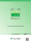
Figure 1. Front Panel
System Indicators
7KH/('LQGLFDWRUVRQWKHIURQWSDQHOSURYLGHLQIRUPDWLRQDERXWWKHIXQFWLRQDQGRSHUDWLRQDOVWDWXVRIWKH9$DQG9$FFKDVVLV
DQGDQ\LQVWDOOHG$0RU$0FDPSOL¿HUPRGXOHV&ROXPQVRQHWKURXJKHLJKWFRUUHVSRQGWRWKHHLJKWDPSOL¿HUPRGXOHVORWV7KH
UHPDLQLQJ/('VFRUUHVSRQGWRWKH9$DQG9$FFKDVVLV
amp fault
activity
signal
&KDQQHO,QGLFDWRUV
status
power
&KDVVLV,QGLFDWRUV
Figure 2. System Indicators
Channel Indicators
Amp FaultLVD\HOORZ/('WKDWLOOXPLQDWHVZKHQDFKDQQHOIDXOWKDVRFFXUUHG7ZRW\SHVRIFKDQQHOIDXOWVFDQEHUHSRUWHGGHSHQGLQJ
RQWKHVHYHULW\RIWKHSUREOHP)ODVKLQJ\HOORZLQGLFDWHVD:DUQLQJZKLFKPHDQVWKDWVRPHDVSHFWRIWKH$0RU$0FDPSOL¿HU
PRGXOHLVQRWSHUIRUPLQJZLWKLQQRUPDOVSHFL¿FDWLRQ$XGLRPD\VWLOOEHSDVVLQJEXWLIWKHFRQGLWLRQFDXVLQJWKH:DUQLQJLVQRWFRUUHFWHG
FKDQQHOIDLOXUHPD\RFFXU6ROLG\HOORZLQGLFDWHVDIDXOWZKLFKPHDQVWKDWVRPHDVSHFWRIWKH$0RU$0FDPSOL¿HUPRGXOHKDV
IDLOHGDQGDXGLRLVQRORQJHUSDVVLQJRQWKDWFKDQQHO8VH9RFLDVRIWZDUHWRGHWHUPLQHWKHVSHFL¿FW\SHRIFKDQQHOZDUQLQJRUIDXOWWKDW
has occurred.
Activity is DWZRFRORU/('WKDWLOOXPLQDWHVLQJUHHQZKHQWKDWFKDQQHOLVFRQ¿JXUHGDQGDFWLYHO\SDVVLQJDXGLRDQG\HOORZZKHQWKDW
FKDQQHOLVFRQ¿JXUHGDQGLQVWDQGE\6WDQGE\RQO\RFFXUVZKHQDFKDQQHOKDVEHHQGHVLJQDWHGDVUHGXQGDQWFKDQQHOLQDFRQ¿JXUDWLRQ
where failover is enabled.
4
VA-8600/VA-8600c FRONT PANEL
SignalLVDWULFRORU/('WKDWLQGLFDWHVDXGLRVLJQDOSUHVHQFHRQWKHFKDQQHO*UHHQLQGLFDWHVWKDWWKHDXGLRVLJQDOOHYHOLVEHWZHHQ -50 dBFS and -3 dBFS, yellow indicates a signal level between -3 dBFS and 0 dBFS, and red indicates clipping.
Chassis Indicators
Amp Fault LVD\HOORZ/('WKDWLOOXPLQDWHVZKHQDFKDVVLVIDXOWKDVRFFXUUHG7KHUHDUHWZRW\SHVRIFKDVVLVIDXOWVWKDWFDQEHUHSRUWHG
depending on the severity of the problem. Flashing yellow indicates a Warning, which means that some aspect of the VA-8600 or VA-8600c FKDVVLVLVQRWSHUIRUPLQJZLWKLQQRUPDOVSHFL¿FDWLRQ$XGLRPD\VWLOOEHSDVVLQJEXWLIWKHFRQGLWLRQFDXVLQJWKH:DUQLQJLVQRWFRUUHFWHGFKDVVLV
failure may occur. Solid yellow indicates a fault, which means that some aspect of the VA-8600 or VA-8600c chassis has failed and audio PD\QRORQJHUEHSDVVLQJWKURXJKWKHGHYLFH8VH9RFLDVRIWZDUHWRGHWHUPLQHWKHVSHFL¿FW\SHRIFKDVVLVZDUQLQJRUIDXOWWKDWKDVRFFXUUHG
ActivityLVDWULFRORU/('WKDWLOOXPLQDWHVWRVKRZWKHFRQ¿JXUDWLRQVWDWXVRIWKH9$DQG9$FXQLW,IWKH/('LVGDUNWKHUHLV
QRFRQ¿JXUDWLRQLQWKHXQLW$JUHHQ/('LQGLFDWHVWKDWWKHXQLWLVFRQ¿JXUHGDQGD\HOORZ/('LQGLFDWHVWKDWWKHXQLWLVFRQ¿JXUHGDQGLQ
VWDQGE\6WDQGE\RQO\RFFXUVZKHQDXQLWKDVEHHQGHVLJQDWHGDVDUHGXQGDQWGHYLFHLQDFRQ¿JXUDWLRQZKHUHIDLORYHULVHQDEOHG$UHG
/('LQGLFDWHVDFRQ¿JXUDWLRQORDGIDLOXUH
StatusLVDWULFRORU/('WKDWLQGLFDWHVWKHKHDOWKRIWKH9$DQG9$FKDUGZDUH$JUHHQ/('LQGLFDWHVWKDWWKHXQLWSRZHUHG
XSQRUPDOO\$ÀDVKLQJ\HOORZ/('LVVKRZQEULHÀ\GXULQJWKHSRZHUXSVHOIWHVWDQGVKRXOGWXUQVROLGJUHHQXSRQVXFFHVVIXOVWDUW$UHG
/('LQGLFDWHVWKDWWKHXQLWH[SHULHQFHGDSUREOHPGXULQJWKHSRZHURQVHOIWHVW
PowerLVDJUHHQ/('WKDWLOOXPLQDWHVZKHQSRZHULVDSSOLHGWRWKHXQLW
Table 1. Channel Indicators
LED Row Label
Red
Yellow
Green
Dark
1
$03)$8/7
1HYHU
Flashing-Warning
Solid-Fault
1HYHU
1R$PS)DXOWV
2
$&7,9,7<
1HYHU
&RQ¿JXUHG and in standby1 &RQ¿JXUHGDQGDFWLYH
1RWFRQ¿JXUHG
3
6,*1$/
Signal above clip threshold (>= 0dBFS)
Signal above peak but below clip threshold
(> -3dBFS & < 0dBFS)
Signal above min. but Signal below min. below peak threshold threshold (< -50dBFS)
(> -50dBFS & < -3dBFS)
4
—
—
—
—
—
Table 2. Chassis Indicators
LED Row Label
Red
Yellow
Green
Dark
1
$03)$8/7
1HYHU
Flashing-Warning
Solid-Fault
1HYHU
1R$PS)DXOWV
2
$&7,9,7<
&RQ¿JXUDWLRQ load failure
&RQ¿JXUHG and in standby2 &RQ¿JXUHGDQGDFWLYH
1RWFRQ¿JXUHG
3
STATUS
3267)DLOXUH
%RRWLQJÀDVKLQJ
Boot succeeded
Did not boot
4
—
—
—
2QO\DSSOLFDEOHRQDPSOL¿HUPRGXOHVFRQ¿JXUHGIRUUHGXQGDQF\RSHUDWLRQ
2QO\DSSOLFDEOHRQDPSOL¿HUPRGXOHVFRQ¿JXUHGIRUUHGXQGDQF\RSHUDWLRQ
5
—
—
VA-8600/VA-8600c REAR PANEL
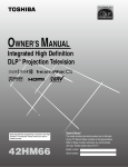
Figure 3. Rear Panel Layout
Device ID Switches
7KHURWDU\,'VZLWFKHVDUHORFDWHGRQWKHEDFNRIWKH9$DQG9$FDQGJLYHWKHXQLWDXQLTXH'HYLFH,'7KHVZLWFKHVDUHLQ
KH[DGHFLPDOIRUPDW$OO9$DQG9$FXQLWVPXVWKDYHDXQLTXH'HYLFH,'WRIXQFWLRQSURSHUO\ZLWKLQD9RFLD3DJLQJ:RUOGLH
LWLVQRWSRVVLEOHWRKDYHWZR9$DQG9$FXQLWVZLWKWKHVDPH'HYLFH,'RIKH[7RDVVLJQD'HYLFH,'RIKH[WXUQWKH
/6%VZLWFKWRDQGOHDYHWKH06%VZLWFKRQ7RFUHDWHDQ,'RIKH[%WXUQWKH/6%VZLWFKWRDQGWXUQWKH06%VZLWFKWR%'HYLFH
,'VZLWFKHVVKRXOGEHVHWXVLQJDLQFKPPWRLQFKPPIODWEODGHVFUHZGULYHU0RUHLQIRUPDWLRQRQVHWWLQJ,'VDQG
WKHKH[DGHFLPDOQXPEHULQJVFKHPHXVHGLQ9RFLDFDQEHIRXQGLQWKH9RFLD+HOS)LOH
Power Entrance
7KH3RZHU(QWUDQFHSURYLGHVIRUFRQQHFWLRQRIWKHDSSURSULDWHSRZHUFRUGLQFOXGHGZLWKXQLW$VZLWFKVHOHFWVWKHRSHUDWLQJYROWDJH IRUWKHSRZHUVXSSO\±9RU±9DW+]
NM-1
10LVWKH1HWZRUN0RGXOHWKDWLVLQFOXGHGZLWK9$DQG9$F7KLVPRGXOHSURYLGHVFRQQHFWLYLW\IRUFRQWURODQGDXGLRYLDWKH
GXDO&REUD1HWLQWHUIDFHDQGORJLFSRUWVIRUWKHGHYLFHIDLORYHUIXQFWLRQDOLW\7KH5-FRQQHFWRUODEHOHG(WKHUQHWLVQRWXVHGDWWKLVWLPH
Reset Button
5HVHWEXWWRQZKHQKHOGGRZQIRUVHFRQGVSHUIRUPVDFKDVVLVUHVWDUW7KH6WDWXVLQGLFDWRUZLOOÀDVK\HOORZGXULQJUHVWDUWDQGZLOOWXUQ
solid green once the process is complete.
Logic I/O
7KH/RJLF,2FRQQHFWRURQWKH10IDFLOLWDWHVUHGXQGDQWGHYLFHIDLORYHURQO\,WLVQRWDJHQHUDOSXUSRVHFRQWDFWFORVXUHLQWHUIDFH 6HHWKH$PSOL¿HUWR$PSOL¿HU)DLORYHUVHFWLRQEHORZ
6
VA-8600/VA-8600c REAR PANEL
Network Connection
7KH9$DQG9$FDUH&REUD1HWGHYLFHV$OO&REUD1HWURXWLQJDQGEXQGOHDVVLJQPHQWVDUHSURFHVVHGE\WKH9RFLDGHYLFHV
ORFDOO\9RFLDPDNHVG\QDPLFXVHRIDYDLODEOHEXQGOHVLQ&REUD1HW9RFLDGHYLFHVDUHFXUUHQWO\QRWLQWHURSHUDEOHZLWKQRQ
9RFLDGHYLFHV$%DVH7(WKHUQHWVZLWFKQRWUHSHDWHUKXELVUHTXLUHGZKHQQHWZRUNLQJPXOWLSOHXQLWV&REUD1HWXWLOL]HV
VWDQGDUG&$7&$7H&$7RU&$7FDEOLQJZKLFKKDVDVSHFL¿HGPD[LPXPOHQJWKRIIHHWPHWHUV$GGLWLRQDO(WKHU-
QHWVZLWFKHVRUVZLWFKHVZKLFKSURYLGHILEHURSWLFLQWHUIDFHFDQEHXVHGWRH[WHQGWKHSK\VLFDOGLVWDQFHEHWZHHQXQLWVZLWKLQD
QHWZRUN3OHDVHQRWHWKDW&REUD1HWOLPLWVQHWZRUNH[WHQVLRQVWRVHYHQKRSVRQHZD\WUDQVPLVVLRQVZLWKLQDQHWZRUN
7KHSULPDU\DQGVHFRQGDU\&REUD1HWSRUWVDUHSURYLGHGWRIDFLOLWDWHFRQQHFWLRQUHGXQGDQF\(DFKFRQQHFWRUSURYLGHVWZR/('VWKDW
LQGLFDWH(WKHUQHWOLQNDQGQHWZRUNDFWLYLW\VHHWDEOHEHORZ
Table 3. CobraNet interface status LEDs
Left LED
Right LED
Description
1RQH
1RQH
1RGDWDFRQQHFWLYLW\
1RQH
Green
Link established.
Flashing yellow
Green
/LQNHVWDEOLVKHGDQG&REUD1HWDFWLYLW\GHWHFWHGWKHXQLWLVDFWLQJDVD&REUD1HWSHUIRUPHU
Flashing yellow
Flashing green
/LQNHVWDEOLVKHGDQG&REUD1HWDFWLYLW\GHWHFWHGWKHXQLWLVRSHUDWLQJDVD&REUD1HWFRQGXFWRU
Flashing yellow
1RQH
&REUD1HWIDXOW&KHFNFDEOLQJDQGFRQ¿JXUDWLRQIRUHUURUV
AM-600/AM-600c
$0RU$0FLVWKH$PSOL¿HU0RGXOHFDUG$9$RU9$FFKDVVLVFDQEHSRSXODWHGZLWKXSWRHLJKW$0RU$0F
FDUGV7KH$0FUHSRUWVDIDXOWLILWGHWHFWVDVKRUWWRJURXQGRQDVSHDNHUOLQHZKHUHWKLVVKRUWZRXOGFRPSURPLVHWKHFDSDELOLW\RIWKH
DPSOL¿HUWRGHOLYHUHPHUJHQF\PHVVDJHV
Output
8VHWKH\HOORZSOXJLQEDUULHUVWULSFRQQHFWRUVWRFRQQHFWORXGVSHDNHUOHYHORXWSXWV,IVWUDQGHGVSHDNHUZLUHLVXVHGEHVXUHWRLQFRUSRUDWH
DOOVWUDQGVLQWRWKHFRQQHFWRUDVVWUD\VWUDQGVFDQVKRUWWRWKHDGMDFHQWWHUPLQDORUFKDVVLV'RQRWOHDYHH[FHVVLYHEDUHZLUHRXWVLGH
the terminals, as this can lead to shorts.
Please note:7KH9$DQG9$FDUHSRZHUIXODPSOL¿HUV
DQGFDQGDPDJHORXGVSHDNHUV3OHDVHWUHDWWKH9$
DQG9$FRXWSXWVDV\RXZRXOG$&PDLQVSRZHURXWOHWV
Always check the loudspeaker’s continuous and peak power FDSDELOLWLHVDQGPDWFKWKHDPSOL¿HUVHWWLQJVDFFRUGLQJO\
7
VA-8600/VA-8600c REAR PANEL
$PSOLÀHUWR$PSOLÀHU)DLORYHU
9RFLDVXSSRUWVRQHWRRQHDXWRPDWLFDPSOL¿HUIDLORYHULQFDVHRIIDXOW)DLORYHULVWULJJHUHGE\RQHRIWKHIROORZLQJFRQGLWLRQV
&KDVVLVIDXOW
&KDQQHOIDXOW
Loss of power
/RVVRI&REUD1HWOLQN
/RVVRI/RJLF,2
Only faults (e.g., heat sink fault and channel failure fault) trigger the failover mechanism. Warnings indicate abnormal system conditions that do not immediately impair audio and do not trigger the failover mechanism. 1 2 3 4
Class 2 Wiring
Logic I/O
Class 2 Wiring
Logic I/O
Primary VA-8600
1 2 3 4
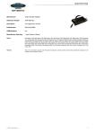
7KHUHGXQGDQWDPSOL¿HUPXVWKDYHWKHVDPHFRQ¿JXUDWLRQDVWKHSULPDU\DPSOL¿HULHDPSOL¿HUPRGXOHFRXQWZDWWVSHUPRGXOHORDG
FRQ¿JXUDWLRQ$ZLUHIDLORYHUOLQNFDEOHPXVWEHFRQQHFWHGEHWZHHQWKHSULPDU\DQGWKHUHGXQGDQWDPSOL¿HUDVVKRZQEHORZ&RQQHFWJURXQG
WRJURXQGDQGORJLFRIWKHSULPDU\DPSOL¿HUWRORJLFRIWKHUHGXQGDQWDPSOL¿HUFRQQHFWORJLFRIWKHSULPDU\DPSOL¿HUWRORJLFRIWKH
UHGXQGDQWDPSOL¿HU/HDYHORJLFDQGGLVFRQQHFWHG7KHUHGXQGDQWDPSOL¿HUFDQEHZLUHGLQSDUDOOHOWRWKHH[LVWLQJVSHDNHUOLQHRULWFDQ
EHFRQQHFWHGWRDUHGXQGDQWVSHDNHUOLQHVHH¿JXUHEHORZ5HOD\VLVRODWHWKHRXWSXWWHUPLQDOVRQWKHVHFRQGDU\9$RU9$F
XQLW5HOD\VDUHQRUPDOO\RSHQ:KHQDFRQ¿JXUDWLRQLVUHFHLYHGUHOD\VFORVHRQWKHSULPDU\9$RU9$FDQGUHPDLQRSHQRQ
the redundant VA-8600 or VA-8600c. On failover, the relay position is switched. Redundant VA-8600
Parallel
Speakers A
Redundant VA-8600
1 2 3 4
Speakers B
Redundant
8
Class 2 Wiring
Logic I/O
1 2 3 4
Class 2 Wiring
Primary VA-8600
Primary VA-8600
Redundant VA-8600
Logic I/O
Primary VA-8600
Redundant VA-8600
1 2 3 4
Class 2 Wiring
Logic I/O
1 2 3 4
Class 2 Wiring
Logic I/O
Redundant VA-8600
Primary VA-8600
$IWHUUHSODFLQJWKHIDXOW\DPSOL¿HUDSRZHUF\FOHLVUHTXLUHGWRUHFRYHUIURPIDLORYHU7KHSULPDU\GHYLFHZLOOUHVXPHFRQWURODIWHUWKHIDLO
condition is cleared and the unit is re-powered.
VA-8600/VA-8600c REAR PANEL
Channel-to-Channel Failover
,QDGGLWLRQWRHQWLUHDPSOL¿HUIDLORYHU9RFLDVXSSRUWVFKDQQHOWRFKDQQHOIDLORYHUZKLFKLVWULJJHUHGE\RQHRIWKHIROORZLQJFRQGLWLRQV
Heat Sink fault
6KRUW&LUFXLWIDXOW
&KDQQHO)DLOXUHIDXOW
The wire failover link cable is not required when wiring channel-to-channel failover.
AM-600
Redundant
Class 2 Wiring
Class 2 Wiring
OUTPUT
Class 2 Wiring
OUTPUT
Class 2 Wiring
OUTPUT
1
AM-600
2
AM-600
1
AM-600
2
Redundant Wiring
OUTPUT
Parallel Wiring
Primary
7KHUHGXQGDQWFKDQQHOFDQEHZLUHGLQSDUDOOHOWRWKHH[LVWLQJVSHDNHUOLQHVKRZQDERYHRUFRQQHFWHGWRDUHGXQGDQWVSHDNHUOLQH 7KHSULPDU\DPSOL¿HUPRGXOHZLOOUHVXPHFRQWURODIWHUWKHIDXOWFRQGLWLRQLVFOHDUHGDQGWKHXQLWLVUHSRZHUHG
9
VA-8600/VA-8600c SPECIFICATIONS
9RFLD$PSOLÀHUF63(&,),&$7,216
Memory:
5.625 MB
Inputs:
20 bits, 48 kHz, 5-1/3 ms (fixed)
Connection:
RJ45 with shielded Ethernet/PoE cable
(CAT5, CAT5e, CAT6, or CAT7)
Total Output Power:
2400W maximum per chassis
(Burst Mode only. Protective thermal limiting
will reduce long-term power output
Environment
Ambient Operating
Temperature Range:
Ambient intake humidity:
Altitude:
Power:
110-120 & 220-240VAC 50/60Hz
Overall Dimensions:
Height:
Width:
Depth:
Weight:
Chassis:
AM 600 card:
5.25 inches (133mm)
19 inches (483mm)
17.25 inches (438mm)
50 lbs. (22.68 kg)
1.25 lbs. (0.57 kg)
Compliance:
FCC Part 15, class B
CE marked
EN 54-16 certified (VA-8600c)
RoHS Directive
UL 60065 Listed, E215636
C-UL Listed, E215636
C-Tick, N24138 (Australia)
18-107 degrees F (-8 – 42° C)
0 – 100% non-condensing
0 – 10,000 Feet MSL
AM-600/600c Card SPECIFICATIONS
Supported Loads:
4ਝߺ 6ਝ, 8ਝߺ70-Volt or 100-Volt Line direct drive
Continuous operation:
in chassis with fans running
normally and unrestricted
intake and exhaust
600 W: 1 kHz continuous sine wave indefinitely
Signal-to-Noise Ratio:
(unweighted over 22 Hz – 20 kHz)
100W
200W
300W
400W
500W
600W
Lowimpedance
>95 dB
>98 dB
>99 dB
>101 dB
>102 dB
>102 dB
70V
>100 dB
>101 dB
>101 dB
>102 dB
>102 dB
>103 dB
100V
>101 dB
>102 dB
>102 dB
>103 dB
>103 dB
>104 dB
10
Frequency
response:
Distortion and
Noise:
Intermodulation
distortion
(SMPTE):
Inter-channel
Isolation:
DC offset:
20 Hz – 20 kHz frequency
response flat +/-1 dB
ɖ0.3% THD+N (20 Hz – 20k Hz) all
loads and power levels
<0.2%
>75 dB
(20 Hz-20 kHz, full power out)
<10mV
VA-8600/VA-8600c SPECIFICATIONS
9RFLD$PSOLÀHUFBLOCK DIAGRAM
NETWORK
MODULE
AMPLIFIER
CARD
SLOT 1
SLOT 2
SLOT 3
SLOT 4
SLOT 5
SLOT 6
SLOT 7
SLOT 8
DSP
DSP
TEMPERATURE
CobraNet
Audio and
control data
SLOT 1
SLOT 2
SLOT 3
SLOT 4
SLOT 5
SLOT 6
SLOT 7
SLOT 8
CobraNet
processor
uC
ID switches
Failover
link
Display
Logic I/O
FAN
CONTROL
FAN
1
FAN
2
11
CLASS D
AMPLIFIER
DC
DETECTION
VA-8600/VA-8600c SPECIFICATIONS
VA-8600/8600c 115 VAC current draw and heat output
7RGHWHUPLQHWKH$&OLQHFXUUHQWGUDZDQGKHDWRXWSXWIRUWKHFRQ¿JXUDWLRQVWDUWE\¿QGLQJWKHWRWDOSRZHUIRUWKHFRQ¿JXUHG9RFLDFKDVVLV
7KHQUHIHUWRWKHFROXPQWKDWGHVFULEHVWKHW\SHRIDXGLROHYHOVWKHDPSOL¿HUZLOOEHSURGXFLQJ,I\RXUFRQ¿JXUDWLRQXVHVPRUHDPSOL¿HU
modules than the number shown, add 0.1 amps and 37 BTU for each additional module in the chassis.
IDLE
1/8 POWER PINK NOISE
1/3 POWER PINK NOISE
FULL POWER SINE WAVE
Total Output Power
(Peak Watts)
VA-8600
Modules
Amps
BTU
Amps
BTU
Amps
BTU
Amps
BTU
No cards
0
0.3
106
NA
NA
NA
NA
NA
NA
100
1
0.4
143
0.7
227
0.9
244
1.6
406
200
1
0.4
143
0.8
239
1.3
271
2.7
491
300
1
0.4
143
1.0
251
1.6
300
3.8
590
400
1
0.4
143
1.1
263
2.0
333
4.9
668
500
1
0.4
143
1.3
278
2.4
356
6.1
788
600
1
0.4
143
1.4
297
2.8
413
7.3
910
700
2
0.5
177
1.8
418
3.4
551
8.9*
1211
800
2
0.5
177
2.0
430
3.8
577
10.0*
1296
900
2
0.5
177
2.1
442
4.2
607
11.1*
1395
1000
2
0.5
177
2.2
454
4.5
640
12.2*
1473
1100
2
0.5
177
2.4
469
4.9
663
13.4*
1592
1200
2
0.5
177
2.5
488
5.3
720
14.5*
1715
1300
3
0.5
211
3.0
609
6.0
858
16.2*
2015
1400
3
0.5
211
3.1
621
6.3
884
17.3*
2101
1500
3
0.5
211
3.2
633
6.7
914
18.4*
2199
1600
3
0.5
211
3.4
644
7.1
947
19.5*
2278
1700
3
0.5
211
3.5
660
7.4
970
20.6*
2397
1800
3
0.5
211
3.7
679
7.8
1026
21.8*
2520
1900
4
0.6
246
4.1
800
8.5
1165
23.4*
2820
2000
4
0.6
246
4.2
812
8.8
1191
24.5*
2905
2100
4
0.6
246
4.4
824
9.2
1221
25.7*
3004
2200
4
0.6
246
4.5
835
9.6
1254
26.7*
3083
2300
4
0.6
246
4.7
851
9.9
1276
27.9*
3202
2400
4
0.6
246
4.8
870
10.4
1333
29.1*
3325
Notes:
)RU9$&PXOWLSO\WKHFXUUHQWE\
31 3LQN1RLVH
For each additional module above 4, add 0.1 A to the current draw and 37 BTU to the heat output. %XUVWPRGHRQO\3URWHFWLYHWKHUPDOOLPLWLQJZLOOUHGXFHORQJWHUP$&FXUUHQWDQGFRQWLQXRXVSRZHURXWSXW
12
VA-8600/VA-8600c WARRANTY
%,$036<67(06,63/($6('72(;7(1'7+()2//2:,1*<($5/,0,7(':$55$17<727+(25,*,1$/385&+$6(52)
7+(352)(66,21$/6281'(48,30(17'(6&5,%(',17+,60$18$/
%,$03 6\VWHPV ZDUUDQWV WR WKH RULJLQDO SXUFKDVHU RI QHZ SURGXFWV WKDW WKH SURGXFW ZLOO EH IUHH IURP GHIHFWV LQ PDWHULDO DQG
ZRUNPDQVKLS IRU D SHULRG RI <($56 IURP WKH GDWH RI SXUFKDVH IURP DQ DXWKRUL]HG %,$03 6\VWHPV GHDOHU VXEMHFW WR WKH terms and conditions set forth below.
,I\RXQRWLI\%,$03GXULQJWKHZDUUDQW\SHULRGWKDWD%,$036\VWHPVSURGXFWIDLOVWRFRPSO\ZLWKWKHZDUUDQW\%,$036\VWHPV
ZLOOUHSDLURUUHSODFHDW%,$036\VWHPV¶RSWLRQWKHQRQFRQIRUPLQJSURGXFW$VDFRQGLWLRQWRUHFHLYLQJWKHEHQH¿WVRIWKLVZDUUDQW\
\RXPXVWSURYLGH%,$036\VWHPVZLWKGRFXPHQWDWLRQWKDWHVWDEOLVKHVWKDW\RXZHUHWKHRULJLQDOSXUFKDVHURIWKHSURGXFWV6XFK
HYLGHQFHPD\FRQVLVWRI\RXUVDOHVUHFHLSWIURPDQDXWKRUL]HG%,$036\VWHPVGHDOHU7UDQVSRUWDWLRQDQGLQVXUDQFHFKDUJHVWR
DQGIURPWKH%,$036\VWHPVIDFWRU\IRUZDUUDQW\VHUYLFHVKDOOEH\RXUUHVSRQVLELOLW\
7KLVZDUUDQW\ZLOOEH92,'LIWKHVHULDOQXPEHUKDVEHHQUHPRYHGRUGHIDFHGRULIWKHSURGXFWKDVEHHQDOWHUHGVXEMHFWHGWR GDPDJHDEXVHRUUHQWDOXVDJHUHSDLUHGE\DQ\SHUVRQQRWDXWKRUL]HGE\%,$036\VWHPVWRPDNHUHSDLUVRULQVWDOOHGLQDQ\
PDQQHUWKDWGRHVQRWFRPSO\ZLWK%,$036\VWHPV¶UHFRPPHQGDWLRQV
(OHFWURPHFKDQLFDOIDQVHOHFWURO\WLFFDSDFLWRUVJRRVHQHFNPLFURSKRQHVFRUGVFRQQHFWLQJKDQGKHOGPLFURSKRQHVKDUGGULYHV
displays, and normal wear and tear of items such as paint, knobs, handles, keypads and covers are not covered under this warranty. All server-based devices are warranted for 3 years only. 7KLVZDUUDQW\LVLQOLHXRIDOORWKHUZDUUDQWLHVH[SUHVVHGRULPSOLHG%,$036\VWHPVGLVFODLPVDOORWKHUZDUUDQWLHVH[SUHVVHG
RULPSOLHGLQFOXGLQJEXWQRWOLPLWHGWRLPSOLHGZDUUDQWLHVRIPHUFKDQWDELOLW\DQG¿WQHVVIRUDSDUWLFXODUSXUSRVH
7KHUHPHGLHVVHWIRUWKKHUHLQVKDOOEHWKHSXUFKDVHU¶VVROHDQGH[FOXVLYHUHPHGLHVZLWKUHVSHFWWRDQ\GHIHFWLYHSURGXFW
1RDJHQWHPSOR\HHGLVWULEXWRURUGHDOHURI%,$03 Systems is authorized to modify this warranty or to make additional warranties on behalf of %,$03 Systems. Statements, representations or warranties made by any dealer do not constitute warranties by %,$03 Systems. %,$03 Systems shall not be responsible or liable for any statement, representation or warranty made by any dealer or other person.
1RDFWLRQIRUEUHDFKRIWKLVZDUUDQW\PD\EHFRPPHQFHGPRUHWKDQRQH\HDUDIWHUWKHH[SLUDWLRQRIWKLVZDUUDQW\
%,$036\VWHPVVKDOOQRWEHOLDEOHIRUVSHFLDOLQGLUHFWLQFLGHQWDORUFRQVHTXHQWLDOGDPDJHVLQFOXGLQJORVWSUR¿WVRUORVVRIXVH
arising out of the purchase, sale, or use of the products, even if %,$03 Systems was advised of the possibility of such damages.
012012_585.0267.90B
13
FCC COMPLIANCE
FCC NOTICE - CLASS B DIGITAL DEVICE NOTE: This equipment has been tested and found to comply with the limits for a Class B digital device, pursuant to Part 15 of the FCC Rules. These limits are designed to provide reasonable protection against harmful interference in a residential as well as in a commercial installation. This equipment generates, uses and can radiate radio frequency energy and, if not installed and used in accordance with the instructions, may cause harmful interference to radio communications. However, there is no guarantee that interference will not occur in a particular installation. If this equipment does cause harmful interference to radio or television reception, which can be determined by turning the equipment off and on, the user is encouraged to try to correct the interference by one or more of the following measures: 1) Reorient or relocate the receiving antenna, 2) Increase the separation between the equipment and receiver, 3) Connect the equipment into an outlet on a circuit different from that to which the receiver is connected or 4) Consult the dealer or an experienced radio/TV technician for help.
14
COMPLIANCE
DoC VADSP201201
EC Declaration of Conformity
Biamp Systems Corporation, as manufacturer having sole responsibility, hereby
declares that the following described product complies with the applicable provisions of
the DIRECTIVES below except as noted herein. Any alterations to the product not
agreed upon and directed by Biamp Systems Corporation will invalidate this declaration.
Products:
Networked Amplified DSP
Models:
VA-8600, VA-8600c,
Vocia Amplifier 8600, Vocia Amplifier 8600c
Vocia Amp and I/O Cards
AM-600, AM-600c, PARM, VFOM-1
Applicable EC Directives:
Applicable Harmonized Standards:
LVD Directive (2006/95/EC)
Safety
EN 60065:2002
EMC Directive (2004/108/EC)
Emissions
Immunity
EN 55103-1:1996, Class B, Environment E2
EN 55103-2:1996, Environment E2
Special Considerations for Product Environment or Compliance:
Shielded cabling must be used for system connections.
Technical Documentation File, Location and Contact:
Biamp Systems Corporation
9300 S.W. Gemini Drive
Beaverton, OR USA 97008
phone:
fax:
e-mail:
(503) 641.7287
(503) 626.0281
[email protected]
Authorized Representative:
Larry Copley, Compliance Engineer
Authorized Signature:
Issued:
Revised:
March 2010
Jan. 2012
15
COMPLIANCE
EU RoHS COMPLIANT
This Biamp product, including all attendant cables and
accessories supplied by Biamp, meets all requirements of EU
Directives 2002/95/EC of January 27, 2003, and 2005/618/EC
of August 18, 2005, the EU RoHS Directives. An EU RoHS
Materials Content Declaration document may be obtained at
www.biamp.com
(This information is presented to comply with the requirements of Chinese law SJ/T11363-2006)”
jK
«¥
Biamp Systems Corporation
eJ6C=dG= (Digital Signal Processor and Amplifier)
Vocia VA-8600 and VA-8600c
©Dl(Equipment Chassis)
Pb
¹
X
Hg
z
O
(Power Cord)
c]TbI (Plug-in Terminal Blocks)
"(CD ROM)
[';%Æfr (Manual and Paper Documents)
.¦;Zj.¦ng (Box and Packing Materials)
O
O
O
O
O
O
O
O
O
O
´8
«Y!
Cd
Cr+6
PBB
¿
$¼
X
O
O
O
O
O
O
O
O
O
O
O
O
O
O
O
O
O
PBDE
O
O
O
O
O
O
0¥ª´Zj@«ng°jvjK
« SJ/T11363-2006 Â,§y.
X¥ª´¢Mj@«ngZ9°jvjK
«È SJ/T11363-2006 Â,§y.
?¨H;Y¾¿Z9@«ng¿3%/7
9µ5¬¯ 0.01%s^ 91/338/EECq`s^
76/769/EECÂ,½<;p0Ä
«;,-´+Zt³ÃE
?YF
«Z9@«ng¹3%/7
9µ5¬¯ 0.1%:
1) I!=&Z9¹
2) ¹?¸ni7¶!9µ5® 0.35%
3) ¹?»ni7¶!9µ5® 0.4%
4) ¹?ºni7¶!9µ5® 4%
5) Èg¹1¹g7¶¹9µ¬¯ 85%
6) IÅ´&¹
7)
!XgZ9¹²b·¡;VC=.¦%
¹9µ¬¯ 80% 85%
8) ÇR·²b&¹
9) LÀUX²
g
?uPW(>k 10 Qoi
CBS 0-40C (32-104°F)
CS 0-95%h*
C}]ÈS 0-10,000 £N
Cw|4Á
C{jxY%~±#´
C 110-120/220-240 Vac, 50/60 Hz, 8/4 A
C´{j_A_A´R1
CO2am:\)ng±¤Zj 16