1
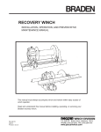
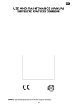
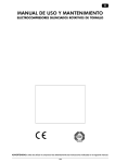
ECO-SMART
A New Member of the R T I Family of Tape and Disc Products
Instruction Manual
•
•
Thank you for purchasing the ECO-SMART.
To operate this unit properly, read this “Instruction Manual”
thoroughly before using. Keep this instruction manual near your
ECO-SMART for quick reference.
WARNING! :
Carefully read and thoroughly understand the important warning
items described in this manual before using the ECO-SMART.
Rev. 1.1
1.1 Safety Explanations
“WARNING!”s and “CAUTION!”s
WARNING!
Do not use this unit in an area where there is flammable or explosive
gas
Never use this unit in an area where there is flammable or explosive gas.
An arc may be generated when the machine’s power switch is turned on or off, and
fire/explosion may result.
Always ground this unit
Always ground this unit on the power equipment side in order to avoid electrical shock
due to a power surge.
If a problem occurs
If smoke or a strange odor should come from this unit, turn off the power switch right
away. Immediately contact a service technician for inspection. If this procedure is not
followed, fire or electrical shock may result.
Never perform repair work yourself. It could be dangerous and is not recommended.
Do not use the power cable if it is bundled or tangled
Do not use the power cable if it is bundled, tangled or damaged. If it is used in this
manner, it can overheat and fire may result.
Do not bend, wring, or stretch the power cable forcibly
Do not bend, wring, or stretch the power cable forcibly. Fire or electrical shock may
result.
Do not disassemble or modify this unit
Do not disassemble or modify this unit. Fire, electrical shock or failure may result.
CAUTION!
During a thunderstorm
During a thunderstorm, turn off the power switch immediately. If this procedure is not
followed, fire or electrical shock or failure may result from lightning strikes.
2
1.2 Contents
1. Safety Precautions
1.1 Safety Explanations …………………………………….………
2
1.2 Table of Contents ………………………..…..…………………...
3
1.3 Specifications, Installation Notes …………..…..…………….
4
2. Items Included …………………………………….…….
5
3. Description and Function of Each Part ……………… 6
4. LED Displays ……………………………………………... 8
5. Pads ………………………………………….……………
8
6. Operation method ……………………………………….. 9
6.1 Prior to Operation …………………………………………….….
9
6.2 Turning ON the power ……………………………………….…..
9
6.3 Operation procedure ………………………..………………..…
10
6.4 Operational Hints …………………………………………………
12
6.5 Cleaning
14
7. Alarm (error) Codes ………………………………….….. 15
8. Replacement Parts ………………………………………. 16
9. Names of Internal Parts.………………………………….. 17
10. Service on your Machine …………………………….…
18
3
1.3 Specifications and Installation Notes
Specifications
ECO-SMART
Model
ECO-SMART
CPU
16 bit RISC Microprocessor
Operation Panel
Operational ambient
Temperature range
Operational ambient
Humidity range
Panel Switch & LED
41 to 95 degrees F
Below 90%
Power supply (50/60Hz)
Dimensions
(W * D * H inches)
100VAC to 240VAC, 150W(MAX)
9” x 16” x 12-1/2” Overall
Weight
Approx. 28 lbs.
1.4. Caution
Do Not open the Front door during repair process.
Do Not place multiple discs on the Disc table.
Do Not place objects on the Operation panel.
Do Not place objects in front of the Front door.
When moving this unit, the drainage tray must be emptied first.
CAUTION!
1. Use the correct power receptacle
Use a power receptacle that meets the unit’s rated electric capacity.
Electric capacity:
ECO-SMART : 100 – 240 VAC, 50/60Hz, 150W(Max)
4
2. Items Included
ECO-SMART. Machine
Power Cord
Drain Hose and Clamp
Replaceable Pads and Permanent Holders
Note: The replaceable pads are shown in the above photo. Make sure these pads are centered on the pad
holders when you attach them. Match the colors of the pad holders with the color of the Velcro of each pad
for Stages 2 through 5. The Stage 1 foam pad with the white Velcro goes on the black colored pad holder.
Starter Supplies and Measuring Cup
5
3. Description and Function of Each Part
Operation Panel
Displays the process stage number
and remaining time, setting values,
and command keys.
STOP button stops the machine
and is also used for opening the
front door.
Disc is inserted on the white platen.
Make sure the side to be repaired is
UP! Label side facing down.
Power switch and
Fuse: 5Amp,250V
FAN
Water Pump
mini-fuse
Water inlet tubing
6
Disc rotator
(Platen drive)
Pad holder drive disc with pad.
When mounting a pad holder, rotate
pad holder until it “snaps” into the
indexing holes of the motorized
metal drive disc.
Disc table platen.
Place the disc here with data side
up and label side down. Otherwise,
the disc will be damaged.
Water Nozzle
Water supply tubing
Goes from bottle of treated distilled
water to pump. Stone filter must be
submerged in water during operation.
Drainage tray
Drainage spout
Waste water collects in this tray
and comes out hose. It removes
with 2 screws for cleaning
Connect drain hose to this spout and run it
into an empty 1 gal. bottle or bucket at least
2 ft. below machine. You may use the metal
hose clamp supplied to prevent leaks.
7
LED Display: ST
LED display: TIME
Process STAGE number
Displays 1 to 5. (Note: Stage 1
is divided into two steps.)
Displays remaining time in each stage
of the disc buffing process. Does not
count down until actual repair starts.
<Process start button>
<Stop button>
Press one of these buttons to start a
desired stage. The number color
corresponds to the correct pad color.
For example, after placing the green
pad on the machine Press “3” to start
the stage 3 process.
Stops the process and automatically
opens front door of the machine.
4. LED Displays
ST LED
Displays the process stage number (1 – 5). If a “9” appears, an error is occurring.
TIME LED
Displays the time remaining in each stage or an error code number if an error occurs.
5. Pads
Process start button
(Stage number)
Standard
time values
[sec.]
Color of Pad
holder
1
2
3
4
5
45
30
40
30
30
Black
Yellow
Green
Red
Blue
8
6. Operation Method
The basic theory of disc repair is to “sand” down the plastic to the bottom of the scratch. This
leaves the disc unplayable due to the scratch marks from the “sanding” process. Therefore, the machine
must polish the disc through several steps, back to a beautiful, shiny disc that looks like new. To
accomplish this polishing, different abrasives made of finer and finer particles are used.
6.1 Prior to operation
•
•
Prepare two bottles or buckets; one for supply water and one for drainage.
Mix Distilled Water in the supply bottle or bucket with “Solution D”. (10 millileters/1 gallon water)
(see page 21 for catalog numbers and supply items)
Use distilled water to achieve the most consistent results!
To mix Solution:
a) Pour about 12 ounces of water from gallon bottle into
another vessel. Keep it off to the side.
b) Add the 10 milliliters of Solution “D” to the gallon bottle.
c) Place the cap on the bottle and shake for 30 seconds.
d) Now add the 12 oz. Of water back into the bottle. Shake
a little and the treated distilled water is ready for use.
Mix Ratio:
10 ml. of solution “D” per 1 gallon of Distilled water
6.2 Turn on the power
•
•
Push the power cable securely into AC inlet on the back of the unit.
Connect the power plug securely to the wall receptacle.
CAUTION!
Receptacle must be grounded!
•
•
•
•
Turn ON the power switch in the rear of the unit.
Automatic initialization sequence will start.
The display will show ST=0 and Time=0.
The front door will automatically open,
so don’t stand too close!.
9
6.3 Operation Procedure
1. Before running your first disk (or 1st. disc of the day), the water supply tube must be primed!
To prime: Open door, press and hold the “Stop” button and press the “Process 5” button until water
squirts constantly from the small tube inside the disc compartment. There may be some air bubbles
so make sure the water stream is constant. Release the buttons.
Then press “STOP” again to turn OFF the water pump.
CAUTION!
Make sure the water tube is primed before running discs.
Processing discs without water will cause problems with the discs.
Shake bottle of treated water at least once a day so that it is well mixed.
2. Place a disc on the white Platen turntable, with the side to be re-surfaced facing UP! Usually this
means the label side is down. For double sided discs, the repair is performed on one side at a time.
Turn the disc over and repeat the repair process for the other side.
3. Place a Pad into its matching Pad Holder then carefully place the Pad Holder onto the metal
drive-disc.
Rotate the pad holder a little to make sure it “snaps” into place on the motorized drive disc, before
starting the process!
CAUTION!
The color of the Pad must match the color of the Pad Holder (except for foam pad 1
which has white velcro and goes on the black pad holder!)
Green Pad is Centered on Green pad holder
Red Pad is being mounted on the red holder
10
CAUTION!
When repairing DVD discs, please do NOT use the Pad 5 process!
4. Close the front door.
5. Push the desired “Process Start Button”. Pad color = Color of “Process Start Button”
When a repair stage is finished, the front door will open automatically. Always use pads in descending
order.
For example: Before repairing a disc, look at the disc’s surface. You determine that starting at stage
3 is appropriate. (This is easy after gaining some experience with disc repair.)
•
•
•
•
Install green pad (3) and press the “3” button. The door will open when finished.
Then install yellow pad (2) and press the “2” button.
Then install the polishing pad (1) and press “1”. Since stage 1 has two parts, the door will open
after the first part (rinse process.)
Now add a drop of polishing compound on the disc (at the 12 O’clock position looking at the
disc.) Then close the door but do not press any numbered buttons! The second part of stage
1 will start automatically.
The Pad 1 process will always be your final process on each disc.
The Pad 1 process is a two part process. The first part will last 15 seconds. It does a
high-speed spin to remove excess water. When complete, the door will open. Place one drop
of “Compound” on the disc, then close the door. The machine will automatically restart and
finish the Pad 1 process (30 seconds.)
DO NOT PRESS ANY KEYS PRIOR TO THE SECOND HALF OF STAGE 1,
JUST CLOSE THE DOOR. THE MACHINE WILL START AUTOMATICALLY.
Transfer some compound into the small bottle for application. Shake the compound well prior to use.
Place a small dab of
compound at the 12
O’clock position for
the second part of
stage 1.
Large Compound Bottle
For the best cost vs. quality results use the following guidelines:
Deep scratches on DVDs: Start with Pad 4
Deep scratches on CDs: Start with Pad 5
Light, medium scratches: Start with Pad 3
Surface clean up: Start with Pad 2
Final Polish: Use pad 1 and use compound
We recommend changing pads (No. 5,4,3 & 2) approximately every 40-50 discs.
11
6.4 Operational Hints:
•
If you want to stop repair a process
immediately, push the red “Stop” button.
All mechanical parts will be stopped
immediately and the “Initialization”
action will be completed.
2) The ECO-SMART does make some noise as it runs, but, If you hear the machine make loud
noises occasionally, there are some things that will prevent it. Here are a few tips:
a. Make sure you are using Distilled Water, not tap water.
b. Make sure you have prepared the water with Solution “D”. 10ml. per gallon of water.
c. Make sure the water supply line into the machine has been primed and the tubing is
free of air bubbles.
d. Occasionally wetting the pad surface, before using, can help. If this noise condition
happens regularly, dip the pad surface briefly into a little water before installing the pad
into the machine.
e. As the pads are used they get filled with white plastic dust from the discs. After every
10th. Disc or so, wipe off the pads with your finger to remove the buildup of dust (you
won’t get it all off, but try to get off some of the excess dust.)
f. If, after following the above tips and the noise continues, change the used pad with a
new one. You will find this is especially true with the yellow and green pads (2 and 3.)
3) The machine may leak water if the drain tube is not be draining properly. Make sure the drain
tube has a downhill slope into the drain bottle or bucket. Eliminate any dips in the drain hose and
arrange the hose so it doesn’t penetrate the surface of liquid in the drain bottle. If the end of the
tube is submerged, the machine may not drain properly and water can leak out of the base of the
machine.
Dip in the tubing prevents drainage
Incorrect
Correct tubing into bottle
Correct
12
4) If an error message occurs, replace the pad for the stage during which the error happened.
This usually clears the error. While the pads will last for 40-50 discs, there are many variables.
Depending on the type of plastic the discs are made of (Clear Polycarbonate, Black, Blue). The
abrasive in the pad can get clogged with debris faster or slower than expected.
5) If you see a small rip or tear in one of the pads, replace it before repairing more discs.
6) Shake the bottle of treated distilled water at least once a day to distribute the Solution “D”
evenly in the water.
7) If the machine just stops working and/or the keyboard stops working properly, turn the machine
off and back ON again. This will clear the electronics and initialize the machine.
8) If the front door does not open and the red button on the keyboard does not make it open, place
a small card into the right-hand side of the slot between the door and the main cabinet. Move the
card to the left. This pushes the latch and the door will open. Never open the door while a disc is
being repaired! Stop the machine or, if necessary, turn the rear power switch OFF before
manually opening the door.
13
RTI ECO-SMART Routine cleaning and maintenance
Congratulations on owning the finest Disc repair/ scratch removal system in the world. It provides
a thorough and easy-to-use restoration for all of your 120mm diameter optical discs such as
DVD’s and CD’s. This product will serve you well for years to come. To ensure reliable operation,
regular cleaning of the machine is necessary.
Here are some tips on cleaning . . .
It is best to use a soft cloth for cleaning the ECO-SMART. Paper towels can be used, but they
may leave paper particles behind. Standard window cleaning solution also helps to dissolve the
disc-repair residue. After 50 discs the machine will get covered with a white residue. This is
primarily very small particles of polycarbonate plastic. As the disc is re-surfaced, a thin layer of
the plastic from the disc is actually removed. But don’t worry, discs can be re-surfaced over a
dozen times and still play perfectly.
Now, about cleaning: Clean off all accessible surfaces with the cloth and cleaning solution. Pay
particular attention to the areas pointed out below. Remove any lint left from cloths.
Clean Rear splash guard and mechanism
Clean out splash tray and under platen
Gently, clean the rubber pad (platen), too
Carefully clean hex shaft and hex spindle
Every few months remove the drain tray (where the hose comes out) and clean it out thoroughly
too. Unscrew the Philips screws on the front and slide out the tray for cleaning.
14
7. Alarm (error) Code
When the unit detects an error status, the LED displays an Alarm Code and mechanical parts are
stopped immediately. (LED displays ST=9, TIME=**)
When an alarm occurs, panel operation is prohibited and the LED TIME display indicates the
Alarm Code.
Please turn off the power switch to clear alarm.
Normally, these error codes indicate a temporary condition that can be easily fixed by
changing pads, cycling power ON/OFF, or a simple adjustment inside the unit.
ST TIME
LED LED
11
12
11
12
31
32
41
42
43
51
52
9
Error-part
SW1 Switch
SW2 Switch
M2
Micro
Motor
M1 DC Motor
Cause
Reason
Action
Open circuit
Short circuit
Open circuit
Short circuit
Open circuit
Short circuit
Open circuit
Short circuit
Over current
Open circuit
Short circuit
Connector No connection
Poor contact
Connector No connection
Poor contact
Sanding Motor overloading
Motor driver damaged
Connector No connection
Poor contact
Motor driver damaged or Over load without water
Connector No connection
Poor contact
A
A
A
A
A
A
A
A
B
A
A
Incorrect step pulses of stepping motor
A
Connector No connection
Poor contact
Motor driver damaged or Over load without water
Connector No connection
Poor contact
Motor driver damaged or Over load without water
EEPROM failed
A
A
A
C
A
A
A
M3 Stepping
Motor
Sensor
for
53
Step out
SE1 Stepping
Motor
61
Open circuit
Water
P1
62
Short circuit
Pump
63
Over current
71
Open circuit
Water
72
Short circuit
Recycle
73
Over current
81
PIC
EEPROM failed
<Action explanation>
A
B
C
Contact a service technician for inspection.
Alarm occurs even though there are no problem with Pad and water,
contact a service technician for inspection.
Alarm occurs even though connector is connected securely. Contact a
service technician for inspection.
15
8. Replacement Parts
Center Rubber
Drainage Pipe
Pad Holders
Pads
<Replacement Parts>
Part Name
Center rubber seal
Drainage Pipe (Hose)
Pad Holder (BLUE)
Pad Holder (RED)
Pad Holder (GREEN)
Pad Holder (YELLOW)
Pad Holder (BLACK)
Stone filter for distilled water
Part No.
EDR-ET-B15
EDR-ET-FN20
EDR-ET-G505
EDR-ET-G504
EDR-ET-G503
EDR-ET-G502
EDR-ET-G501
EDR-ET-FN21
Specification
Part No.
10440
10442
10444
10446
10448
10451 / 10450
10454
Call RTI
Specification
Rough Sanding
Medium Sanding
Fine Sanding
Finish Sanding
Polishing Pad
120mm bottle / 750ml bottle
500ml
Specify color needed
<Consumable Materials>
Part Name
Pad (BLUE)
Pad (RED)
Pad (GREEN)
Pad (YELLOW)
Pad (BLACK)
Polish Compound
Solution “D”
Replacement Velco discs
16
9. Names of Components of the ECO-SMART:
The photos below will give you the names for the major components of the machine.
Door Latch
Platen Motor
Door Solenoid
Sanding Motor
Sanding LIFT Motor
Door “Closed” Microswitch
Sanding Motor Coupler
Sanding Lift Position Sensor
Sanding Lift Motor
Gears, Sanding Lift Mechanism
Side view
17
RTI Group
4700 Chase Ave. - Lincolnwood - IL USA - 60712
10. Service on Your
Machine
Your disc repair machine
deals with a significant
Phone: 1-800-323-7520
number
of
variable
Fax: 1-847-677-1311
factors.
The friction
between the disc and
the
sanding
pads
E-mail: [email protected]
changes constantly as
the pads are gradually
worn down. The water supply can vary a little due to small air bubbles in the line. The
amount of Solution “D” can vary if the water is not mixed properly or the bottle of supply
water is not shaken or stirred occasionally. The pads may not be centered on the pad
holders. All of these factors determine the friction during the repair process and the
operation of the machine. The machine is under software control and if the electrical
sensors in the machine detect changes in these frictions, it is possible that error
messages may occur from time to time that are temporary in nature. These temporary
errors can usually be addressed by changing the pads or just turning the machine OFF
and then ON again to reset the electronics.
In the unlikely event that a persistent problem occurs, note the error code (if any) and the
nature of the problem, turn off the power switch, and unplug the machine. Please contact
the RTI Service Department.
Please have the following information available:
•
•
•
•
Approximate date you received the machine
Model Name of the product
Serial Number (Located on the rear Identification label)
Problem description (please provide as much detail as possible).
If the machine needs factory service, make sure to include your name and address, phone
number, and a description of the problem with the machine. Repairs can cost more and take
longer without this information.
18
19