1
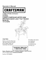
Operator's Manual
®
15 AMP 3 HP (Max. Developed)
10" Blade
4800 R.P.M.
LASER COMPOUND
MITER SAW
With Retractable Laser Trac® System
Model No.
137.212540
CAUTION:
Before using this Miter Saw,
read this manual and follow
all its Safety Rules and
Operating Instructions
•
•
Safety Instructions
Installation
•
•
Operation
Maintenance
•
Parts List
Customer
Help Line
1-800-843-1682
Sears, Roebuck and Co., Hoffman Estates, IL 60179 U.S.A.
Visit our Craftsman website: www.sears.com/craftsman
Part No.:137212540001
SECTION
Warranty ........................................
Product Specifications .......................
Power Tool Safety ............................
Compound Miter Saw Safety ...............
Electrical Requirements and Safety ......
Accessories and Attachments ..............
Tools Needed For Assembly ................
Carton Contents ..............................
PAGE
2
2
3
4
4-5
6
6
7
SECTION
Know Your Compound Miter Saw ........
Glossary of Terms ............................
Assembly and Adjustments .................
Operation .......................................
Changing Laser Batteries ..................
Maintenance ...................................
Troubleshooting Guide .......................
Parts List .........................................
PAGE
8
9
10
17
23
24
25
26
FULL ONE YEAR WARRANTY
If this tool fails due to a defect in material or workmanship
at its option repair or replace it free of charge.
within one year of date of purchase,
Sears will
Return this tool to a Sears Service Center for repair, or to place of purchase for replacement.
This warranty gives you specific legal rights, and you may also have other rights which may vary from
state to state.
Sears, Roebuck and Co., Dept. 817 WA, Hoffman Estates, IL 60179
Some dust created by power sanding, sawing, grinding, drilling and other construction activities contains
chemicals known to cause cancer, birth defects or other reproductive harm. Some examples of these chemicals
are:
• Lead from lead-based paints
• Crystalline silica from bricks, cement and other masonry products
• Arsenic and chromium from chemically treated lumber
Your risk from these exposures varies, depending on how often you do this type of work. To reduce your
exposure to these chemicals, work in a well ventilated area and work with approved safety equipment such as
dust masks that are specially designed to filter out microscopic particles.
MOTOR
Power Source .........................
Horsepower ..........................
Arbor Shaft Size
120 VAC, 60HZ, 15Amp
3HP (Max. Developed)
5/8"
Speed .....................................
Brake .....................................
Double Insulated ........................
4800 RPM (No load)
Electric
Yes
MITER SAW
Bevel Positive Stops ...............
Base Dimensions ...................
Extension
Cutting Capacity:
Crosscut .................................
Miter 45 ° R. & L ......................
Bevel 45 ° L ...........................
450 Miter and 45 ° Bevel .............
Rotating Table:
Diameter ..............................
Miter Detent Stops ..................
Tables ....................
Net Weight ...........................
2-5/8"
2-5/8"
1-1/2"
1-1/2"
x
x
x
x
12-1/2"
0, 15, 22-1/2, 31.6,
45 ° R. & L.
0, 45 o
19" x 16-1/4"
Left & Right
47 Lbs
5-1/2"
3-1/2"
5-1/2"
3-1/2"
To avoid electrical hazards, fire hazards or damage to the tool, use proper circuit protection.
This tool is wired at the factory for 110-120 Volt operation. It must be connected to a 110-120 Volt / 15 Ampere
time delay fuse or circuit breaker. To avoid shock or fire, replace power cord immediately if it is worn, cut or
damaged in any way.
Before using this tool, it is critical that you read and understand these safety rules. Failure to follow these rules
could result in serious injury to you or damage to the tool.
GENERAL
BEFORE
SAFETY
12.ALWAYS WEAR EYE PROTECTION. Any power tool
can throw foreign objects into the eyes and
could cause permanent eye damage.
ALWAYS wear Safety Goggles (not
glasses) that comply with ANSI Safety
standard Z87.1 Everyday eyeglasses
have only impact -resistance lenses.
They ARE NOT safety glasses. Safety Goggles are
available at Sears. NOTE: Glasses or goggles not in
compliance with ANSI Z87.1 could seriously injure
you when they break.
INSTRUCTIONS
USING THIS POWER TOOL
Safety is a combination of common sense, staying alert
and knowing how to use your power tool.
To avoid mistakes that could cause serious injury, do not
plug the tool in until you have read and understood the
following.
1. READ and become familiar with the entire Operators
Manual. LEARN the tool's application, limitations and
possible hazards.
13.WEAR A FACE MASK OR DUST MASK. Sawing
operation produces dust.
2. KEEP GUARDS IN PLACE and in working order.
14.SECURE WORK. Use clamps or a vise to hold work
when practical, It's safer than using your hand and it
frees both hands to operate the tool,
3. REMOVE ADJUSTING KEYS AND WRENCHES.
Form the habit of checking to see that keys and
adjusting wrenches are removed from the tool before
turning ON.
1&DISCONNECT TOOLS FROM POWER SOURCE
before servicing, and when changing accessories
such as blades, bits and cutters.
4. KEEP WORK AREA CLEAN. Cluttered areas and
benches invite accidents.
16.REDUCE THE RISK OF UNINTENTIONAL
STARTING. Make sure switch is in the OFF position
before plugging the tool in.
5. DON'T USE IN DANGEROUS ENVIRONMENTS.
Don't use power tools in damp locations, or expose
them to rain or snow. Keep work area well lighted.
17.USE RECOMMENDED ACCESSORIES. Consult this
Operators Manual for recommended accessories. The
use of improper accessories may cause risk of injury
to yourself or others.
6. KEEP CHILDREN AWAY. All visitors and bystanders
should be kept a safe distance from work area.
18.NEVER STAND ON THE TOOL. Serious injury could
occur if the tool is tipped or if the cutting tool is
unintentionally contacted.
7. MAKE WORKSHOP CHILD PROOF with padlocks,
master switches, or by removing starter keys.
19.CHECK FOR DAMAGED PARTS. Before further use
of the tool, a guard or other part that is damaged
should be carefully checked to determine that it will
operate properly and perform its intended function check for alignment of moving parts, binding of moving
parts, breakage of parts, mounting, and any other
conditions that may affect its operation. A guard or
other part that is damaged should be properly repaired
or replaced.
8. DON'T FORCE THE TOOL. It will do the job better
and safer at the rate for which it was designed.
9. USE THE RIGHT TOOL. Do not force the tool or an
attachment to do a job for which it was not designed.
10.USE PROPER EXTENSION CORDS. Make sure your
extension cord is in good condition. When using an
extension cord, be sure to use one heavy enough to
carry the current your product will draw. An undersized
cord will result in a drop in line voltage and in loss of
power which will cause the tool to overheat. The table
on page 5 shows the correct size to use depending on
cord length and nameplate ampere rating. If in doubt,
use the next heavier gauge. The smaller the gauge
number, the heavier the cord.
20.NEVER LEAVE THE TOOL RUNNING UNATTENDED.
TURN THE POWER "OFF". Don't walk away from a
running tool until the blade comes to a complete stop
& unplug the unit.
21 .DON'T OVERREACH. Keep proper footing and
balance at all times.
22.MAINTAIN TOOLS WITH CARE. Keep tools sharp
and clean for best and safest performance. Follow
instructions for lubricating and changing accessories,
11 .WEAR PROPER APPAREL. Do not wear loose
clothing, gloves, neckties, rings, bracelets, or other
jewelry which may get caught in moving parts. Nonslip
footwear is recommended. Wear protective hair
covering to contain long hair.
23.WARNING: Dust generated from certain materials can
be hazardous to your health. Always operate saw in
well-ventilated area and provide for proper dust
removal.
.3
SPECIFIC SAFETY INSTRUCTIONS
COMPOUND MITER SAW
FOR THIS
1. USE ONLY CROSS-CUTTING SAW BLADES. When
using carbide tipped blades, make sure they have a
negative hook angle.
IMPORTANT: DO NOT USE THIN KERF BLADESthey can deflect and contact guard and can cause
possible injury to the operator.
2. DO NOT operate the miter saw until it is completely
assembled and installed according to these
instructions.
3. IF YOU ARE NOT thoroughly familiar with the operation
of miter saws, seek guidance from your supervisor,
instructor, or other qualified person.
4. ALWAYS hold the work firmly against the fence and
table. DO NOT perform any operation free hand (use
clamp wherever possible).
5. KEEP HANDS out of the path of the saw blade. If the
workpiece you are cutting would cause your hands to
be within 7-1/4" inches of the saw blade, the workpiece
should be clamped in place before making the cut.
18.MAKE SURE the blade is not contacting the workpiece
before the switch is turned ON.
19.IMPORTANT: After completing the cut, release the
power switch and wait for the blade to stop before
returning the saw to the raised position.
20.MAKE SURE the blade has come to a complete stop
before removing or securing the workpiece, changing
the workpiece angle, or changing the angle of the
blade.
21 .NEVER cut metals or masonry products with this tool.
This miter saw is designed for use on wood and
wood-like products.
22.NEVER cut small pieces. If the workpiece being cut
would cause your hand or fingers to be within 7-1/4"
inches of the saw blade the workpiece is too small.
23.PROVIDE adequate support to the sides of the saw
table for long work pieces.
24.NEVER use the miter saw in an area with flammable
liquids or gases.
6. BE SURE the blade is sharp, runs freely, and is free of
vibration.
25.NEVER use solvents to clean plastic parts. Solvents
could possibly dissolve or otherwise damage the
material.
7. ALLOW the motor to come up to full speed before
starting a cut.
26.SHUT OFF the power before servicing or adjusting the
tool.
8. KEEP THE MOTOR AIR SLOTS CLEAN and free of
chips or dust.
27.DISCONNECT the saw from the power source and
clean the machine when finished using.
9. ALWAYS MAKE SURE all handles are tight before
cutting, even if the table is positioned in one of the
positive stops.
28.MAKE SURE the work area is clean before leaving the
machine.
10.BE SURE both the blade and the collar are clean and
the arbor bolt is tightened securely.
11.USE only blade collars specified for your saw.
12. NEVER use blades larger or smaller in diameter than
10-inches.
29.SHOULD any part of your miter saw be missing,
damaged, or fail in any way, or any electrical
component fail to perform properly, shut off the switch
and remove the plug from the power supply outlet.
Replace missing, damaged, or failed parts before
resuming operation.
13. NEVER apply lubricants to the blade when it is
running.
14. ALWAYS check the blade for cracks or damage before
operation. Replace a cracked or damaged blade
immediately.
15. NEVER use blades recommended for operation at less
than 4800 RPM.
16.ALWAYS keep the blade guards in place and use at all
times.
17.NEVER reach around the saw blade.
POWER SUPPLY AND MOTOR SPECIFICATIONS
The AC motor used in this saw is a universal,
nonreversible type. See "MOTOR" in the "PRODUCT
SPECIFICATIONS" section on page 2.
To avoid electrical hazards, fire hazards, or damage to the
tool, use proper circuit protection. Your saw is wired at the
factory for 120V operation. Connect to a 120V, 15 Amp
circuit and use a 15 amp. time delay fuse or circuit breaker.
To avoid shock or fire, if power cord is worn or cut, or
damaged in any way, have it replaced immediately.
ELECTRICAL
REQUIREMENTS
DOUBLE INSULATED
- cont'd
[]
The power tool is double insulated to provide a double
thickness of insulation between you and tool's electrical
system. All exposed metal parts are isolated from the
internal metal motor components with protecting insulation.
Replacement parts - When servicing use only identical
replacement parts.
Polarized plugs - This saw has a plug that looks like the
one shown below:
4. FUSES may "blow" or circuit breakers may trip
frequently if:
a. MOTOR is overloaded - overloading can occur if
you feed too rapidly or make too many start/stops
in a short time.
b. LINE VOLTAGE is more than 10% above or below
the nameplate voltage rating. For heavy loads, the
voltage at motor terminals must equal the voltage
specified on the nameplate.
c. IMPROPER or dull saw blades are used.
5. Most motor troubles may be traced to loose or incorrect
connections, overload, low voltage or inadequate power
supply wiring. Always check the connections, the load
and supply circuit if the motor doesn't run well. Check
minimum gauge for the length of cord you are using on
the chart below.
GUIDELINES FOR EXTENSION CORDS
....
_:: : !i¸
To reduce the risk of electrical shock, this saw has a
polarized plug (one blade is wider than the other). This
plug will fit in a polarized outlet only one way. If the plug
does not fit fully in the outlet, reverse the plug. If it still
does not fit, contact a qualified electrician to install the
proper outlet. Do not change the plug in any way.
Double insulation does not take the place of normal safety
precautions when operating this tool.
To avoid electrocution:
1. Use only identical replacement parts when servicing a
tool with double insulation. Servicing should be performed
by a qualified technician.
2. Do not use power tools in wet or damp locations or
expose them to rain or snow.
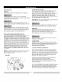
MOTOR SAFETY
PROTECTION
IMPORTANT:
To avoid motor damage, the motor should be blown out or
vacuumed frequently to keep sawdust from interfering with
the motor ventilation.
1. CONNECT this saw to a 120'7, 15 amp. circuit with a 15
amp. time delay fuse or circuit breaker. Using the wrong
size fuse can damage the motor.
2. If the motor won't start, release the trigger switch
immediately. UNPLUG THE SAW. Check the saw blade
to make sure it turns freely. If the blade is free, try to
start the saw again. If the motor still does not start, refer
to the "TROUBLESHOOTING GUIDE"
3. If the tool suddenly stalls while cutting wood, release the
trigger switch, unplug the tool, and free the blade from
the wood. The saw may now be started and the cut
finished.
Use a proper extension cord. Make sure your extension
cord is in good condition. When using an extension cord,
be sure to use one heavy enough to carry the current your
product will draw. An undersized cord will cause a drop in
line voltage, resulting in loss of power and cause
overheating. The table below shows the correct size to use
depending on cord length and nameplate ampere rating. If
in doubt, use the next heavier gauge. The smaller the
gauge number, the heavier the cord.
Be sure your extension cord is properly wired and in
good condition. Always replace a damaged extension cord
or have it repaired by a qualified person before using it.
Protect your extension cords from sharp objects, excessive
heat and damp or wet areas.
Use a separate electrical circuit for your tools. This
circuit must not be less than # 12 wire and should be
protected with a 15 Amp time delay fuse. Before
connecting the tool to the power line, make sure the switch
is in the OFF position and the electric current is rated the
same as the current stamped on the motor nameplate,
running at a lower voltage will damage the motor.
II Lv_
II_IhV_
|ll Lv_
[cf:ll[_ :11_[e]t.i :lKii :1__,"][e]_[_e] t._;}.lf:YAVLc_ll
(When using 120 volts only)
Ampere Rating
Total length of cord in feet
more than
25'
50'
100'
0
not more than
6
18
16
16
150'
14
6
10
I8
I6
I4
12
10
12
16
16
14
12
12
16
14
12
not recommended
CAUTION: In all cases make certain the receptacle in
question is properly grounded. If you are not sure have a
certified electrician, check the receptacle.
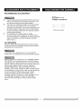
RECOMMENDED
•
•
•
ACCESSORIES
Use only accessories recommended for this miter saw.
Follow instructions that accompany accessories. Use
of improper accessories may cause hazards.
The use of any cutting tool except 10 inch saw blades
that meet the requirements under recommended
accessories is prohibited. Do not use accessories such
as shaper cutters or dado sets. Ferrous metal cutting,
the use of abrasive wheels and the cutting of masonry
products are prohibited.
Do not attempt to modify this tool or create
accessories not recommended for use with this tool.
Any such alteration or modification is misuse and could
result in a hazardous condition leading to possible
serious injury.
ACCESSORIES
Visit your Sears Hardware Department or see the Sears
Power and Hand Tool Catalog to purchase recommended
accessories for this power tool.
To avoid the risk of personal injury, do not modify this
power tool or use accessories not recommended by Sears.
Read warnings and conditions on your CARBIDE TIPPED
SAW BLADE. Do not operate the saw without the proper
saw blade guard in place. Carbide is a very hard but brittle
material. Care should be taken while mounting, using, and
storing carbide tipped blades to prevent accidental
damage. Slight shocks, such as striking the tip while
handling, can seriously damage the blade. Foreign objects
in the workpiece, such as wire or nails, can also cause tips
to crack or break off. Before using, always visually
examine the blade and tips for bent teeth, cracks,
breakage, missing or loose tips, or other damage. Do not
use if damage is suspected. Failure to heed safety
instructions and warnings can result in serious bodily
injury.
Phillips
screwdriver
13mm Hex wrench
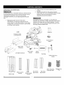
UNPACKING YOUR MITER SAW
,
3.
To avoid injury from unexpected starting or electrical shock,
do not plug the power cord into a source of power during
unpacking and assembly. This cord must remain
unplugged whenever you are adjusting/assembling
the
saw,
Remove the miter saw from the carton.
IMPORTANT: Do not lift the miter saw by the
switch handle or miter table handle. It may cause
misalignment. Lift only by the built in carry handle
on the top of the machine.
Place the saw on a secure stationary work
surface.
Separate all parts from the packing material.
Check each one with the illustration below to make
certain all items are accounted for, before
discarding any packing material.
If any part is missing or damaged, do not attempt to
assemble the miter saw, or plug in the power cord until the
missing or damaged part is correctly replaced. To avoid
electric shock, use only identical replacement parts when
servicing double insulated tools.
11
Batteries
Extension Table
Locking Screws
Elbow
Dust Collector
Right Table
Extension
Left Table Extension
Miter Table
Handle
Blade
Wrench
Dust Bag
Safety Hold-down
Clamp
I tl
Stand Legs
Stand Mounting
Hardware Bag
Top (short)
Bottom (short)
bracket
Bottom (long)
bracket
leg bracket
Top (long)
leg bracket
Rubber Foot
Pad
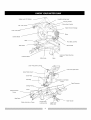
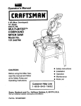
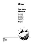
Safety Lock-OFF Button
Handle Locking Lever
Carrying Handle
Cutting Head Handle
ON / OFF Switch
Blade Wrench Storage
Laser Trac g_
Motor
Carbide Blade
Table
Pivot Bolt Lock-Nut
Table Insert
Bevel Scale
Extension Table Mounting
Holes
Positive Detent
Miter Scale
Base
Laser Trac guide Locking
Laser Trac guide lever
Upper Blade Guard
Cover Plate
Dust Bag
Retractable Lower Blade
Guard
Table Extension
Sliding Fence
Fence
Table Extension
Fence
Stop Block
Safety Hold-down Clamp
Positive Stop
Locking Lever
Miter Handle
Quick-Cam
Miter Lock
CRAFTSMAN
COMPOUND
MITER SAW TERMS
ARBOR LOCK - Allows the user to keep the blade from
rotating while tightening or loosening the arbor locking
bolt during blade replacement or removal.
BASE - Supports the table, holds accessories
allows for workbench or leg set mounting.
and
BEVEL LOCKING HANDLE - Locks the miter saw at a
desired bevel angle.
BEVEL SCALE - To measure the bevel angle of the saw
blade 0° to 45 ° left.
COVER PLATE SCREW - Loosen this screw and rotate
the plate for access to the blade arbor locking bolt.
DUST CHUTE - Exhausts debris away from the user.
EXTENSION TABLE - Extends the width of the work
table for support while cutting long work pieces. They
can be used with or without a stop block as an additional
side fence.
FENCE - Helps to keep the workpiece from moving
when sawing. Scaled to assist with accurate cutting.
HAND HOLD - Location of hands for transportation.
SAFETY LOCK-OFF BUTTON - Yellow button on
handle must be pushed forward to activate the trigger
switch.
LOWER BLADE GUARD - Helps protect your hands
from the blade in the raised position, it retracts as the
blade is lowered.
MITER HANDLE - Used to rotate the saw to the right or
left cutting position.
MITER SCALE - To measure the miter angle 0 ° to 45 °
left, 0 ° to 45 ° right.
MITER SPRING LOCK - Used in combination with the
miter handle, it locks the miter saw at a preset positive
stop for the desired miter angle.
MOUNTING HOLES stable surface.
To mount the miter saw to a
ON/OFF TRIGGER SWITCH - To prevent the trigger
from being accidentally engaged, a lock-off slide switch
is provided. To start the tool, push the lock-off slide
switch forward and squeeze the trigger. Release the
trigger to stop the miter saw.
STOP LATCH - Locks the miter saw in the lowered
position for compact storage and transportation.
SWITCH HANDLE - The cutting head handle contains
the trigger switch and a safety lock-off slide switch. The
blade is lowered into the workpiece by pushing down on
the handle. The saw will return to its upright position
when the handle is released.
WARNING LABELS - Read and understand for your
own safety. Always make certain these are in place &
legible.
WRENCH STORAGE - Convenient storage to prevent
misplacing the blade wrench.
WOODWORKING
TERMS
ARBOR - The shaft on which a blade is mounted.
BEVEL CUT - An angle cut made through the face of
the workpiece.
COMPOUND CUT -A simultaneous bevel and miter cut.
CROSS CUT - A cut made across the width or grain of
the workpiece.
FREEHAND - Performing a cut without using a fence
(guide), hold down or other proper device to prevent the
workpiece from twisting during the cutting operation.
GUM -A sticky sap from wood products.
HEEL - Misalignment of the blade.
KERF - The amount of material removed by blade cut.
MITER CUT - An angle cut made across the width or
grain of the workpiece.
RESIN -A sticky sap that has hardened.
REVOLUTIONS PER MINUTE (RPM) - The number of
turns completed by a spinning object in one minute.
SAW BLADE PATH - The area of the workpiece or table
top directly in line with the travel of the blade or the part
of the workpiece which will be cut.
SET - The distance between two saw blade tips, bent
outward in opposite directions to each other. The further
apart the tips are, the greater the set.
WORKPIECE - The item being cut. The surfaces of a
workpiece are commonly referred to as faces, ends, and
edges.
ASSEMBLY INSTRUCTIONS
To avoid injury, do not connect this miter saw to the
power source until it is completely assembled and
adjusted, and you have read and understood this
Operators Manual.
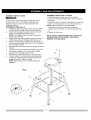
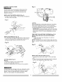
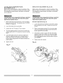
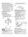
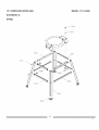
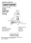
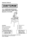
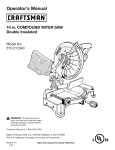
ASSEMBLE STAND (Fig. 1)
1. Unpack all parts and group by type and size. Refer
to the parts list on page 32 for correct quantities.
2. Attach one long upper support (4) to top of leg (1)
using one carriage bolt (2) and nut (5).
NOTE: Hand-tighten bolts until stand is properly
aligned (see step #8).
3. Attach other end of long upper support to the top of
another leg using one carriage bolt and one nut.
4. Attach one long bottom support (3) to the center of
each leg using carriage bolt and nut. This completes
the front frame section.
5. Assemble the rear frame section in exactly the same
manner.
6. Join the front and rear frame assemblies using two
short upper supports (tl) and two short bottom
supports (10), carriage bolts and nuts.
7. Place all four rubber feet pads (7) onto each leg.
8. Place the stand on a level surface and adjust it so
all legs are contacting the floor and are at similar
angles to the floor. Tighten all bolts.
NOTE: Stand should not rock after all bolts are
tightened.
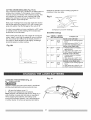
ASSEMBLE MITER SAW TO STAND
1.Carefully place the miter saw on top of stand.
2.Line up the three mounting holes in the saw base to
the stand.
3. Fasten the saw to the stand using the three mounting
bolts (12), three washers (t3) and three nuts (t4).
NOTE: Place a washer on each bolt before
inserting it into the saw base and through the
support, then thread the nut onto the bolt (see Fig.
1)
4.Tighten all three nuts.
NOTE: DO NOT OVER TIGHTEN THE LOCK NUTS
HOLDING SAW TO THE STAND. THIS COULD
DAMAGE THE SAW BASE.
Fig. 1
!1
14
3
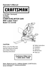
ASSEMBLY INSTRUCTIONS
Fig. C
To avoid injury, do not connect this miter saw to the
power source until it is completely assembled and
adjusted, and you have read and understood this
Operator's Manual.
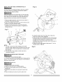
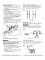
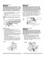
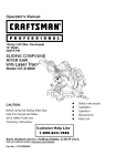
INSTALLING THE MITER HANDLE (Fig. A)
1. Thread the miter handle (1)into the hole (2)located at
the front of the miter table.
Fig. A
Locking
When transporting or storing the miter saw, the cutting
head should always be locked in the down position.
1. Push the cutting head (3) down to its lowest position.
2. Push the stop latch (2) into the locking hole (4).
IMPORTANT: To avoid damage, never carry the miter
saw by the switch handle, the cutting arm, or the miter
table handle. ALWAYS use the designated carrying
handle.
1
2
SAW BLADE WRENCH (Fig. B)
1. For convenient storage and prevention of loss, there is
a slot (1) in the rear of the cutting head handle (2) for
storing the blade wrench (3) when not in use.
Fig. B
2
\
1
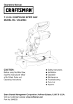
THE DUST COLLECTION
SYSTEM (Fig. D, E)
INSTALLING THE DUST COLLECTION ELBOW
(Fig. D)
1. Install the larger end of the elbow (1) onto the
exhaust port (2).
NOTE: The elbow can be used to attach either the dust
bag or a vacuum hose to remove sawdust from the work
area.
Fig. D
1
3
\
CUTTING HEAD (Fig. C)
Raising
1. Push down slightly on the cutting handle.
2. Pull out the stop latch knob (2).
3.Allow the cutting head (3) to raise to the up position.
To avoid injury and damage to the saw, transport or store
the miter saw with the cutting head locked in the down
position. Never use the stop latch to hold the cutting
head in a down position for cutting operations.
INSTALLING THE DUST BAG (Fig. E)
1. Squeeze the metal collar wings (t) of the dust bag
(2).
2. Place the dust bag neck opening around the exhaust
port (3), and release the metal collar wings.
t
3
Fig. E
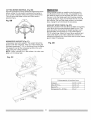
INSTALLING THE TABLE EXTENSION (Fig. F)
Fig. G
To avoid injury or possible damage to the tool, support
long work pieces by installing the extension table to
extend the work support surface.
When using extension and stop block on the right side,
hold clown clamp must also be in right side. Using hold
clown clamp on the left side during this operation can
cause kick-back and serious injury to the operator.
1
2
1. Place the table extension rods into the two holes (1)
provided in the miter saw base.
2. Insert one Phillips head screw (2) into the hole (3) and
tighten to hold the extension table.
3. Loosen the locking knob (4), slide the stop block
assembly (5) to the desired location, re-tighten the
locking knob (4).
Fig. F
2
1
NOTE:
1. The Fig. F only shows the installation of the left
extension table. Repeat these procedures for the right
extension table. Only one stop block is included with
the machine.
2. The Stop Block may install on either side of the
extension supports.
REMOVING OR INSTALLING THE BLADE
1. Only use a 10-inch diameter blade.
2. To avoid injury from an accidental start, make sure the
switch is in the OFF position and plug is not connected to
the power source outlet.
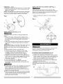
REMOVING (Fig. G, H, I)
1. Unplug the saw from the outlet.
2. Raise the miter saw to its' upright position.
3. Loosen the cover plate screw (2) with a Phillips
screwdriver.
4. Rotate the cover plate (3) to expose the arbor bolt
(4).
5. Place the blade end wrench over the arbor bolt.
6. Locate the arbor lock (5) on the motor, below the
miter saw switch handle. (Fig. H)
7. Press the arbor lock, holding it in firmly while turning
the blade wrench clockwise. The arbor lock will then
engage and lock the arbor. Continue to hold
the arbor lock, while turning the wrench clockwise to
loosen the arbor bolt.
8. Raise the lower clear plastic blade guard (1) to the
upright position. (Fig. G)
Fig. H
REMOVING
- cont'd
9. Remove
thearborboltandwasher(4),theouterblade
collar(6),andtheblade(7).Donotremovetheinner
bladecollar.(Fig.I)
NOTE:Payattention
tothepiecesremoved,
notingtheir
positionanddirection
theyface.Wipethebladecollars
cleanofanysawdust
beforeinstalling
a newblade.
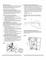
INSTALLING THE HOLD-DOWN CLAMP (Fig. J)
When using the stop block on the extension table,
place the hold clown clamp on the same side. Using the
clamp on the opposite side can cause kick-back and
serious injury to the operator.
1. Place the Hold-down Clamp (1) on the mounting
hole (2).
Fig. I
Fig. J
1
7
7
INSTALLING A BLADE (Fig. G, H, I)
Un-plug the miter saw before changing/installing the
blade.
1. Install a 10" blade, making sure the rotation arrow
on the blade matches the clockwise rotation arrow on
the upper guard, and the blade teeth are pointing
downward.
2. Place the outer blade collar (6) against the blade and
on the arbor. Thread the arbor bolt (4) on the arbor.
(Fig. I)
IMPORTANT: Make sure the flats of the blade collars are
engaged with the flats on the arbor shaft. Also, the
flat-side of the arbor collar must be placed against the
blade.
3. Place the blade wrench on the arbor bolt.
4. Press the arbor lock (5), holding it in firmly while
turning the blade wrench counterclockwise. When
it engages, continue to press the arbor lock in,
while tightening the arbor bolt securely. (Fig. H)
5. Rotate the cover plate (3) back to its original position
until the slot in the cover plate engages with the cover
plate screw (2). Tighten the screw with a Phillips
screwdriver. (Fig. H)
6. Lower the blade guard (1). (Fig. G)
7. Be sure the arbor lock is released so the blade
turns freely by spinning the blade until the arbor lock
disengages.
To avoid injury from an accidental start, make sure the
switch is in the OFF position and the plug is not
connected to the power source outlet.
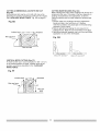
ADJUSTING FENCE SQUARENESS (Fig. K)
1. Loosen the three fence locking screws (1).
2. Position the cutting head in the lower locked position.
Using a square, lay the heel of the square against the
blade, and the rule against the fence (2) as shown.
Check to see if the fence is 90 ° to the blade.
3.Adjust the fence 90 ° to the blade and re-tighten the
three fence locking screws.
CAUTION: If the saw has not been used recently,
recheck blade squareness to the fence and readjust if
needed.
1
2
1
• Always make sure the unit is unplugged. To avoid injury,
never use the saw without the cover plate secure in
place. It keeps the arbor bolt from falling out if it
accidentally loosens, and helps prevent the spinning
blade from coming off the saw.
• Make sure the collars are clean and properly arranged.
Lower the blade into the lower table and check for any
contact with the metal base or the turn table by
spinning the blade manually.
]3
MITERSCALE(Fig.L)
Themitersawtablehasnineofthemostcommon
angle
settings with positive stops at 0°, 15°, 22.5 °, 31.6° and
45 °. These positive stops position the blade at the
desired angle quickly and accurately.
Miter Angle Pointer Adjustment (Fig. L):
1. Place the miter table at the zero position making sure
the positive stop locking lever snaps into position.
2. Loosen the miter angle indicator screw (3) and adjust
the indicator to the "0" mark on the miter scale.
3.Tighten miter angle indicator screw.
ADJUSTING AUXILIARY FENCES (Fig. M)
1. First make sure the miter saw fence is square to the
blade (see Adjustments Fig. K) and adjust if necessary.
2.Loosen the two extension wing fence screws (1).
3. Using a square, lay the heel of the square against the
blade, and the rule against the auxiliary fence (2) as
shown. Check to see if the fence is 90 ° to the blade.
4.Adjust the auxiliary fence 90 ° to the blade and in line
with the Miter Saw Fence, retighten the two fence
screws (1).
5. Repeat for other side.
CAUTION: If the saw has not been used recently,
recheck blade squareness to the fence and readjust if
needed,
Positive Stop Miter Angle Adjustment:
1. Unlock the miter table by pressing down on the
positive stop locking lever (1).
2. While holding the positive stop locking lever down,
grasp the miter handle (2) and move the miter table
left or right to the desired angle.
3. Release the positive stop locking lever and set the
miter at the desired angle making sure the lever
snaps into place.
Quick-Cam Miter Table Lock Operation:
If miter angles required are NOT one of the nine positive
stops noted above, the miter table can be locked at any
angle between these positive stops by using the Miter
Quick-Cam table lock.
1. Unlock the miter table by pressing down on the
positive stop locking lever (1).
2. While holding the positive stop locking lever down,
grasp the miter handle (2) and move the miter table
left or right to the desired angle.
3. Release the positive stop locking lever.
4. Press down on the Miter Quick-Cam locking lever (4)
until it locks the miter table in place.
NOTE: The miter Quick-Cam locking lever should
lock the table and prevent it from moving. If
adjustment is needed, see next step.
Quick-Cam Miter Table Lock Adjustment:
1. Press down and lock the Quick-cam locking lever (4).
This provides room to fit the wrench into position.
2. Loosen the Quick-Cam lock nut (5) using a 13 mm
wrench and release the Quick-cam lock.
3. Turn the adjusting screw (6) either in or out until the
locking lever firmly locks the miter table in place.
4. Tighten Quick-Cam locking nut.
_g. M
2
t
Ci
d
ADJUSTING EXTENSION TABLE (Fig. N)
If the extension table is not flush with the miter table,
adjust the four leveling knobs (t) accordingly until it is
level with the table.
Fig. N
®
Fig. L
14
CUTTING HEAD DOWNWARD TRAVEL
ADJUSTMENT (Fig. P)
Before each cutting operation, check the position of the
blade to make sure it does not contact any metal surface,
If it contacts any metal surface, the depth of movement
can be adjusted,
BEVEL STOP ADJUSTMENT (Fig. Q & R)
To avoid injury from unexpected starting or electrical
shock, turn the switch OFF and remove the power
cord from the power source.
To avoid injury from unexpected starting or electrical
shock, turn the switch OFF and remove the power
cord from the power source.
1.
90° Bevel adjustment (Fig. Q)
Before attempting this adjustment, move the sliding
fence as far to the LEFT as possible (see "SLIDING
FENCE" on Page 20).
2.
Lower the blade as far as possible.
3.
Loosen lock nut (3) using a 10 mm wrench.
4.
Turn the adjusting bolt (4) IN to lower the maximum
cutting depth and OUT to raise the maximum cutting
depth.
6.
Before each cutting operation, check the position of the
blade to make sure it does not contact any metal surface.
If it contacts any metal surface, the depth of movement
can be adjusted.
1.
Loosen the bevel lock handle (1) and tilt the cutting
arm completely to the right. Tighten the bevel lock
handle.
2.
Place a combination square (2) on the miter table
with the rule against the table and the heel of the
square against the saw blade.
,
If the blade is not 90 ° square with the miter table,
loosen the bevel lock handle, turn the bevel angle
adjusting screw (3) in or out with a 10mm wrench
from underneath the table until the blade is square
with the table.
Lower the blade to the new maximum depth and
manually rotate the blade with a wooden block to
make sure it does not contact any metal surface.
NOTE: Repeat adjustment if the blade contacts any
metal surface.
4.
Tighten lock nut.
Fig. Q
Fig. P
]5
Tighten bevel lock handle.
BEVELSTOPADJUSTMENT (Fig. Q & R) - Cont'd
90 ° Bevel indicator (Fig. R)
5. When the blade is exactly g0 ° to the table, loosen the
LEFT bevel indicator screw (5) using a Phillips
screwdriver.
6. Adjust the LEFT bevel indicator (6) to the "0" mark (7)
on the bevel scale and retighten the screw.
45 ° Bevel adjustment
7. Unlock the bevel lock handle and tilt the cutting arm
as far to the left as possible.
8. Using a combination square, check to see if the
blade angle is 45°to the table.
9. If the blade is not at 45 ° to the miter table, loosen the
lever (1), turn the bevel angle adjusting screw (4) in
or out with a 10mm wrench from underneath the
table until the blade is at 45 ° to the miter table.
10. Tighten the bevel lock handle.
45 ° Bevel indicator (Fig. R)
11. When the blade is exactly 45 ° to the table, loosen the
RIGHT bevel indicator screw (8) using a Phillips
screwdriver.
12. Adjust RIGHT bevel indicator (9) to the 45 o mark (10)
on the bevel scale and retighten the screw.
Fig. R
Parallel Laser Beam Adjustment (Fig. S)
Lower the cutting head so the blade is flush with the side
of the scribed line. Turn on the laser beam, loosen the
screw (4 - Fig. U) _¼turn and adjust the thumbscrew (2 Fig. U) accordingly then retighten the screw (4).
Fig. S
m
m
i
Laser
b_m
B. Angle Adjustment
If the laser-beam is not parallel to the scribed line (Fig T),
adjust the screw (3 - Fig. U) with a Phillips screwdriver.
_o
Be careful not to overturn the adjustment screw. The
maximum turn for the screw (3) is +/- 5,or approximately
1/8 turn (Fig. S) to prevent any possible wire damage.
Fig. T
Laser-beam
/
ALIGNING THE LASER GUIDE (Fig. S, T, U)
C. Laser Position Adjustment
For your own safety, never connect the plug to power
source outlet until all the adjustment steps are
complete and you have read and understood the
safety and operational instructions.
If the Laser Beam moves when the upper cutting arm is
raised and lowered, adjust the screw (1) cautiously with a
slotted screwdriver +/- 5° or approximately 1/8 turn.
A. How to Check Laser-beam Alignment
1. Find a 90 ° square scrap workpiece and scribe a 90 °
line as the calibrating pattern and position the
workpiece on the table.
2. Turn on the laser and line up the laser beam with the
scribed line.
Fig. U
3.
Lower the cutting head to verify the blade is parallel
to the side of the scribed line.
]6
SAFETY INSTRUCTIONS
OPERATION
FOR BASIC SAW
Keep all guards in place, in working order and
proper adjustment.
If any part of this miter saw is missing, bent
damaged or broken in any way, or any electrical
parts don't work, turn the saw off and unplug it.
Replace damaged, missing, or defective parts
before using the saw again.
BEFORE USING THE MITER SAW
To avoid mistakes that could cause serious, permanent
injury, do not plug the tool in until the following steps are
completed:
•
•
•
•
•
Completely assemble and adjust the saw, following
the instructions. (ASSEMBLY AND
ADJUSTMENTS)
Learn the use and function of the ON/OFF switch,
lock-off switch, upper and lower blade guards, stop
latch, bevel lock handle, and cover plate screws.
Review and understand all safety instructions and
operating procedures in this Operator's
ManuaI.(SAFETY & OPERATIONS)
Review the MAINTENANCE and
TROUBLESHOOTING GUIDE for your miter saw.
To avoid injury or possible death from electrical
shock:
Make sure your fingers do not touch the plug's metal
prongs when plugging or unplugging your miter saw.
(ELECTRICAL REQUIREMENTS AND SAFETY)
Maintain tools with care. Keep the miter saw clean
for best and safest performance. Follow instructions
for lubricating. Don't put lubricants on the blade
while it's spinning.
•
USE ONLY RECOMMENDED ACCESSORIES
•
Consult the ACCESSORIES and ATTACHMENTS
section of this Operators Manual for recommended
accessories. Follow the instructions that come with
the accessory. The use of improper accessories may
cause risk of injury to persons.
Choose the correct 10 inch diameter blade for the
material and the type of cutting you plan to do. D._o_o
not use Thin Kerr blades.
Make sure the blade is sharp, undamaged and
properly aligned. With the saw unplugged, push the
cutting arm all the way down. Manually spin the
blade and check for clearance. Tilt the miter head to
a 45 ° bevel and repeat the test.
BEFORE EACH USE
Inspect your saw.
•
Disconnect the miter saw. To avoid injury from
accidental starting, unplug the saw before any
adjustments, including set-up and blade changes.
Remove all adjusting wrenches from the tool before
turning it on.
•
Make sure the blade and arbor collars are clean.
Compare the direction of rotation arrow on the
guard to the direction arrow on the blade. The blade
teeth should always point downward at the front of
the saw.
•
Make sure all clamps and locks are tight and there is
no excessive play in any parts.
Tighten the arbor bolt.
Cluttered areas and benches invite accidents.
Tighten the cover plate screw.
Check for damaged parts. Check for:
•
Alignment of moving parts
•
Damaged electric cords
•
Binding of moving parts
•
Mounting holes
•
Function of arm return spring and lower guard:
Push the cutting arm all the way down, then let
it rise until it stops. The lower guard should
fully close. Follow instructions in
TROUBLESHOOTING GUIDE for adjustment.
•
Other conditions that may affect the way the
miter saw works.
To avoid burns or other fire damage, never use the miter
saw near flammable liquids, vapors, or gases.
•
Plan ahead to protect your eyes, hands, face and
ears.
•
Know your miter saw.
Read and understand the Operator's Manual and labels
affixed to the tool. Learn its application and limitations as
well as the specific potential hazards peculiar to this tool.
To avoid injury from accidental contact with moving parts,
don't do layout, assembly, or setup work on the miter
KEEP YOUR WORK AREA CLEAN
saw,
•
Avoid accidental starting
Make sure the switch is OFF before plugging the
miter saw into a power outlet.
PLAN YOUR WORK
Use the right tool. Don't force a tool or attachment to
do a job it was not designed to do. Use a different
tool for any workpiece that can't be held in a solidly
braced, fixed position.
CAUTION: This machine is NOT designed for cutting
masonry, masonry products & ferrous metals (steel, iron,
and iron-based metals.) Use this miter saw to cut only
wood, wood-like products, or soft metals like aluminum.
Other material may shatter, bind the blade, or create
other dangers. Remove all nails that may be in the
workpiece to prevent sparking that could cause a fire.
DRESS FOR SAFETY
Any power tool can throw foreign objects into the eyes.
This can result in permanent eye damage. Everyday
eyeglasses have only impact resistant lenses and are not
safety glasses. Glasses or goggles not in compliance
with ANSI Z87.1 could seriously injure you when they
break.
•
Do not wear loose clothing, gloves, neckties or
jewelry (rings, watches). They can get caught and
draw you into moving parts.
•
Wear non-slip footwear.
•
Tie back long hair.
•
Roll long sleeves above the elbow.
•
Noise levels vary widely. To avoid possible hearing
damage, wear ear plugs when using any miter saw.
•
For dusty operations, wear a dust mask along with
safety goggles.
INSPECT YOUR WORKPIECE
Make sure there are no nails or foreign objects in the part
of the workpiece being cut.
Plan your work to avoid small pieces that may bind,
or that are too small to clamp and get a solid grasp
on,
Plan the way you will grasp the workpiece from start to
finish. Avoid awkward operations and hand positions. A
sudden slip could cause your fingers or hand to move
into the blade.
DON'T OVER-REACH
Keep good footing and balance. Keep your face and
body to one side, out of the line of a possible kickback.
NEVER stand in the line of the blade.
Never cut freehand:
•
Brace your workpiece firmly against the fence and
table stop so it will not rock or twist during the cut.
•
Make sure there is no debris between the workpiece
and the table or fence.
•
•
•
•
Make sure there are no gaps between the workpiece,
fence and table that will let the workpiece shift
during the cut.
Keep the cut off piece free to move sideways after it
is cut off. Otherwise, it could get wedged against the
blade and thrown, possibly causing injury.
Only the workpiece should be on the saw table.
Secure work. Use clamps or a vise to help hold the
work when it's practical.
USE EXTRA CAUTION WITH LARGE OR ODD
SHAPED WORKPIECES.
•
•
•
•
•
Use extra supports (tables, sawhorses, blocks, etc.)
for workpieces large enough to tip.
Never use another person as a substitute for a table
extension, or as an additional support for a
workpiece that is longer or wider than the basic
miter saw table, or to help feed, support, or pull the
workpiece.
Do not use this saw to cut small pieces. If the
workpiece being cut would cause your hand or
fingers to be within 7-1/4" inches of the saw blade
the workpiece is too small. Keep hands and fingers
out of the "no hands zone" area marked on the saws
table.
When cutting odd shaped workpieces, plan your
work so it will not bind in the blade and cause
possible injury. Molding, for example, must lie flat or
be held by a fixture or jig that will not let it move
when cut.
Properly support round material such as dowel rods,
or tubing, which have a tendency to roll when cut,
causing the blade to "bite".
To avoid injury, follow all applicable safety instructions,
when cutting non-ferrous metals:
•
Use only saw blades specifically recommended for
non-ferrous metal cutting.
•
Do not cut metal workpieces that must be hand held.
Clamp workpieces securely.
•
Cut non-ferrous metals only if you are under the
supervision of an experienced person.
WHEN SAW IS RUNNING
Don't allow familiarity from frequent use of your miter saw
to result in a careless mistake. A careless fraction of a
second is enough to cause a severe injury.
Before cutting, if the saw makes an unfamiliar noise or
vibrates, stop immediately. Turn the saw OFE Unplug the
saw. Do not restart until finding and correcting the
problem.
BODYANDHANDPOSITION
(Fig.V)
Properpositioning
ofyourbodyandhandswhen
operating
themitersawwillmakecuttingeasier and
3.
4.
safer.
Never place hands near the cutting area. Place hand at
least 7-1/4" away from the path of the blade. Hold
workpiece firmly against the fence to prevent movement
toward the blade. Keep hands in position until the trigger
has been released and the blade has completely stopped.
Before making a cut, with the power switch in the OFF
position bring the saw blade down to the workpiece to
see the cutting path of the blade.
•
Keep children away. Keep all visitors a safe distance
from the miter saw. Make sure bystanders are clear
of the miter saw and workpiece.
•
Don't force the tool. It will do the job better and safer
at its designed rate. Feed the saw into the workpiece
slowly with a firm downward motion.
Before freeing jammed
material:
•
Turn switch OFR
•
Unplug the miter saw.
•
Wait for all moving parts to stop.
Fig. W
THREE POSITION ROTATING HANDLE (Fig. X)
The handle of the miter saw has been designed to rotate
and lock at three different positive stops; 0 _,45 °, and 90 o
for operator convenience. To rotate the handle:
1. Unlock the red handle locking lever (4) by pulling it
toward the front of the machine.
2. Pull the red handle-locking latch (5) to the front of the
saw and hold in position.
3. Rotate the handle to 0°, 45o or 90° and release the
handle-locking latch.
NOTE: After releasing the handle-locking latch,
rotate the handle left and right to make sure the latch
engages into the positive locking position.
4. Lock the red handle-locking lever by pushing it
toward the rear of the handle.
NOTE: The tightness of the rotating handle can be
adjusted by the following steps:
1. Loosen the four screws (6), and remove the carry
handle (7).
2. If the rotating handle (8) is too loose or tight, adjust
the nut (9) clockwise or counter clockwise with a
13mm wrench.
3. Replace the carry handle and four screws.
After finishing a cut:
•
•
•
Hold the upper cutting head down.
Release the switch, and wait for all moving
parts to stop before moving your hands.
If the blade doesn't stop within 6 seconds,
unplug the saw and follow the instructions in
THE TROUBLESHOOTING
GUIDE section before
using the saw again.
Fig. V
o
Lock the laser guide assembly into place by pushing
the locking lever to the right side of the saw.
To turn the laser ON or OFF, press the rocker switch
(3).
i
Fig. X
i
k
J
I
\
L
i_\
7-1/4"
!
\
/I
//
7-1/4"
TURNING THE SAW ON (FIG. X)
To reduce the likelihood of accidental starting, a thumb
activated yellow lock-OFF switch is located on top of the
switch handle. The safety lock-OFF button (t) must be
pushed forward
before the trigger switch (2) can be
activated and the miter saw started.
Make the switch child-proof.
Insert a padlock through the
hole (3) in the trigger switch and lock it. This will prevent
children and other unauthorized
users from turning the
switch ON. (Fig. X)
LASER TRAC ON/OFF SWITCH (Fig. W)
Laser radiation. Avoid direct eye exposure.
Always un-plug miter saw from power source before
making any adjustment.
1. Unlock the laser guide lever (t) by pulling it out
toward the left side of the saw.
2. Slide out on the laser guide assembly by pulling on
the tab (2).
]9
SLIDING FENCE (Fig. Y)
BEVEL CUT (Fig. Z-l)
The sliding fence must be fully extended to the left
when making any compound or bevel cuts. Failure
to fully extend the sliding fence will not allow enough
space for the blade to pass through, which could
result in serious injury. At extreme miter or bevel
angles the saw blade may also contact the fence.
The sliding fence must be fully extended to the left
when making any compound cuts. Failure to fully
extend the sliding fence will not allow enough space
for the blade to pass through, which could result in
serious injury. Failure to extend the fence may cause
the saw blade to make contact with the fence.
1. When a bevel cut is required, loosen the bevel lock
handle (1). Tilt the cutting head to the desired angle as
shown on the bevel scale (2). The blade can be
positioned at any angle, from a 90 ° straight cut (0 ° on the
scale) to a 45 ° left bevel. Tighten the lock handle (1) to
lock the cutting head in position. Positive stops are
provided at 0 ° and 45 °.
1.
Unlock the fence cam locking lever (1) by pushing it
toward the rear of the machine.
2. Fully extend the fence by sliding it out as far as
possible (2).
3. Lock the fence cam lock by pushing it IN toward the
fence.
NOTE: When transporting the saw, always secure the
sliding fence in the collapsed position (toward the saw
blade).
Fig. Y
MITER CUT (Fig. Z)
1. Unlock the miter table by pressing down on the
positive stop locking lever (2).
2. While holding the positive stop locking lever down,
grasp the miter handle (1) and move the miter table
left or right to the desired angle.
3. Release the positive stop locking lever, making sure
it engages the positive stop. Slight movement of the
miter handle left or right will ensure positive stop
engagement.
NOTE: Positive stops at provided at 0°, 15°, 22.5°,
3t .6° and 45 ° right and left.
NOTE: If the miter angle required is NOT one of the
positive stops noted above, the miter table can be
locked at any angle between these positive stops by
using the Quick-Cam miter lock (see Page 14).
Fig. Z
-1
Fig.
Z-1
COMPOUND CUT (Fig. AA)
The sliding fence must be fully extended to the left
when making any compound cuts. Failure to fully
extend the sliding fence will not allow enough space
for the blade which could result in serious injury. At
extreme compound angles the saw blade may also
contact the fence.
1. Fully extend the fence by sliding it out as far as
possible. See "SLIDING FENCE" on this page.
Set the desired bevel angle using the bevel lock
handle (1) see "BEVEL CUT" above.
Set the desired miter angle using the positive stop
locking lever (3) and the Quick-Cam miter lock. See
"MITER CUT" on this page.
Fig. AA
/
CUTTING BOWED MATERIAL (Fig. BB)
A bowed workpiece must be positioned against the fence
before cutting. Do not position workpiece incorrectly or
try to cut the workpiece without the support of the fence.
This will cause the blade to bind and could result in
personal injury.
Fig. BB
When making multiple or repetitive cuts that result in
cut-off pieces of one inch or less, it is possible for the
saw blade to catch the cut-off piece and throw it out of
the saw or into the blade guard and housing, possibly
causing damage or injury. To minimize this risk, turn off
the machine, wait until the blade comes to a complete
stop, unplug the unit & remove the cut pieces.
AUXILARY WOOD FENCE (Fig. DD)
Holes are provided in the saw fence to attach an auxiliary
wood fence (this provides additional depth of cut). This
fence should be constructed of straight auxiliary wood
approximately 3/4 inch thick by 2-1/2 inches high by
18-1/2 inches long. Attach the wood fence securely and
make a full depth cut to make a blade slot. Check for
interference between the wood fence and the lower blade
guard. Adjust if necessary.
WORKPIECE SUPPORT (Fig. CC)
Long pieces need extra support. The support should be
placed under the workpiece. Keep your hand holding the
workpiece positioned 7-1/4" or more away from the blade.
The support must let the workpiece lay flat on the work
table during the cutting operation.
NOTE: When mounted on a flat surface, the miter saw
table is 3-1/8 inches high.
Fig. DD
Fig. CC
Cutting
capacity
Crosscut
Miter 45°R.
fence
3-1/2" x 3-1/2"
& L.
3-1/2" x 2"
Bevel 45°L.
Compound
with auxiliary
2" x 3-1/2"
45°L.,45°R
& L.
2" x 2"
CUTTING A DIMENSIONAL 4X4 WITH ONE CUT
(Fig. EE)
A dimensional 4x4 may be cut in half with one cut by
attaching an auxiliary wood fence of 3/4 inch thick board.
See "AUXILIARY WOOD FENCE" Fig. DD on page 21
CUTTING BASE MOLDING (Fig. GG)
Base moldings and many other moldings can be cut on a
compound miter saw. The setup of the saw depends on
molding characteristics and applications, as shown.
Perform practice cuts on scrap material to achieve best
results:
1. Always make sure moldings rest firmly against the
fence and table. Use hold-down or C-clamps,
whenever possible, and place tape on the area being
clamped to avoid marks.
2. Reduce splintering by taping the cut area prior to
making the cut. Mark the cut line directly on the tape.
3. Splintering typically happens due to an incorrect blade
application or use of thin kerf blades.
Fig. EE
Auxiliary
fence
i_
3.1/2,
_.t..Workpiece
M,,e,, ZLtoo
Fig. GG
Miter saw table
t
Miter saw table
Miter at 45 °, bevel
VERTICAL MITER CUTTING (Fig. FF)
To make a miter cut in a 2x4 workpiece (1-5/8" x 3-1/2")
in the vertical position on edge, a spacer such as the
auxiliary wood fence described in the "AUXILIARY
WOOD FENCE".
Fig. FF
Auxiliary
Miter saw fence
(
fence
_1-5/8"_)_,J
/Workpiece
_
[, ))
Miter saw
22
at 0 _'
--ram7
Miter at 0 e, bevel at 45 °
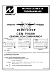
CUTTING
CROWNMOULDING (Fig. HH, II)
Your compound miter saw is suited for the difficult task of
cutting crown molding. To fit properly, crown molding
must be compound-mitered with extreme accuracy. The
two surfaces on a piece of crown molding that fit flat
against the ceiling and wall are at angles that, when
added together, equal exactly 90 °.
Settings for standard crown molding lying flat on
compound miter saw table.
Fig. II
Most crown moldings have a top rear angle (the section
that fits flat against the ceiling) of 52 ° and a bottom rear
angle (the section that fits flat against the wall) of 38 °.
In order to accurately cut crown molding for a 90 ° inside
or outside corner, lay the molding with its broad back
surface flat on the saw table.
When setting the bevel and miter angles for compound
miters, keep in mind that the angles for crown molding
are very precise and difficult to set exactly. Since it is
very easy for these angles to shift slightly, all settings
should be tested on scrap molding.
\
Compound cut crown moldings
Bevel/Miter Settings
KEY
BEVEL
MITER
SETT NG SETT NG
TYPE
Inside
IL
33.9 °
31.6 °
Right
corner-Left
OF CUT
side
1. Position top of molding against
fence.
2.Miter table set at RIGHT 31.6 °.
3. LEFT side is finished piece.
Inside corner-Right
side
Fig. HH
IR
.......
33.9 °
t
31.6 °
Left
F
1. Position bottom of molding
against fence.
2. Miter table set at LEFT 31.6 ° .
3. LEFT side is finished piece.
Outside
corner-Left
side
OL
33.9 °
Q
@
31.6 °
Left
1. Position bottom of molding
against fence.
2. Miter table set at LEFT 31.6 °.
3. RIGHT
Mite
saw tab_e
OR
33.9 °
31.6 °
Right
side is finished
fence.
2. Miter table set at RIGHT
3. RIGHT
side is finished
Fig. JJ
CHANGING THE BATTERIES (Fig. J J)
•
Unplug your saw.
1
Failure to unplug your saw could result in accidental
starting causing possible serious personal injury.
1. Lift open the battery cover (1).
2. Remove and replace the two batteries.
Note: Replace with batteries that have a rating of 1.5
volts (Number 4 series and AAA size or equivalent).
When replacing the batteries, the battery cover
should be thoroughly cleaned. Use a soft paintbrush
or similar device, to remove all sawdust and debris.
piece.
Outside
corner-Right
side
1. Position top of molding against
31.6 °.
piece.
LOWER BLADE GUARD
Do not use the saw without the lower blade guard. The
lower blade guard is attached to the saw for your
protection. Should the lower guard become damaged, do
not use the saw until the damaged guard has been
replaced. Develop a regular check to make sure the
lower guard is working properly. Clean the lower guard of
any dust or buildup with a damp cloth.
MAINTENANCE
DANGER
Neverputlubrican_onthebladewhileitisspinning.
Toavoidfireortoxicreaction,
neverusegasoline,
naphtha
acetone,lacquerthinnerorsimilarhighlyvolatile
solventstocleanthemitersaw.
CAUTION: Do not use solvents on the guard. They could
make the plastic "cloudy" and brittle.
Toavoidinjuryfromunexpected
startingorelectrical
shock,unplugthepowercordbeforeworkingonthesaw.
When cleaning the lower guard, unplug the saw from the
power source receptacle to avoid unexpected startup.
Foryoursafety,thissawis double-insulated.
Toavoid
electrical
shock,fireor injury,useonlypartsidentical
to
thoseidentified
inthepartslist.Reassemble
exactlyas
theoriginalassembly
toavoidelectrical
shock.
SAWDUST
Periodically, sawdust will accumulate under the work
table and base. This could cause difficulty in the
movement of the worktable when setting up a miter cut.
Frequently blow out or vacuum up the sawdust.
REPLACING
CARBON
BRUSHES
(Fig.KK)
Thecarbonbrushes
furnished
willlastapproximately
50
hoursofrunningtime,or 10,000ON/OFF
cycles.
Replace
bothcarbonbrusheswheneither has less than
If blowing sawdust, wear proper eye protection to keep
debris from entering eyes.
1/4" length of carbon remaining, or if the spring or wire is
damaged or burned. To inspect or replace brushes, first
unplug the saw. Then remove the black plastic cap (1) on
the side of the motor (2). Remove the cap cautiously,
because it is spring-loaded. Then pull out the brush and
replace. Replace the other side in the same manner. To
reassemble, reverse the procedure. The ears on the
metal end of the assembly go in the same hole the
carbon part fits into. Tighten the cap snugly, but do not
overtighten.
LUBRICATION
All the motor bearings in this tool are lubricated with a
sufficient amount of high grade lubricant for the life of the
unit under normal operating conditions; therefore, no
further lubrication is required.
Lubricate the Following as Required:
Chop pivot: light machine oil or aerosol will penetrate
from the ends of the junction points. A qualified service
technician can remove the pivot upstop to relieve tension,
and the 2 metric set screws holding the shaft, in order to
drive the shaft about 3/4" right. Exposed surfaces are
lubricated with automotive type oil.
NOTE: To reinstall the same brushes, first make sure the
brushes go back in the way they came out. This will
avoid a break-in period.
Fig. KK
Central pivot of plastic guard: Use light household oil
(sewing machine oil ) on metal-to-metal or
metal-to-plastic guard contact areas as required for
smooth, quiet operation. Avoid excessive oil, to which
sawdust will cling.
Link: (which actuates the lower guard movement) may be
oiled at the rear pivot, greased at ball bearing contact,
and oiled where the link actuates the acetyl roller of the
lower guard, if the down chop motion is hard to start.
24
Toavoidinjuryfromaccidental
starting,alwaysturntheswitchOFFandunplugthetoolbeforemoving,replacing
the
bladeor makingadjustments.
ConsultyourSearsServiceCenterifforanyreasonthemotorwillnotrun.
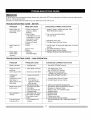
TROUBLESHOOTING
GUIDE - MOTOR
PROBLEM
PROBLEM CAUSE
SUGGESTED CORRECTIVE ACTION
Brake does not
stop blade within
6 seconds.
1. Motor brushes not
sealed or lightly
sticking.
2. Motor brake
overheated from use
of defective or wrong
size blade or rapid
ON/OFF cycling.
3.Arbor bolt loose.
4. Other.
1. Fuse
1. Inspect/clean / replace brushes. See
MAINTENANCE section.
Motor does not
start
Brush spark
when switch
released.
TROUBLESHOOTING
2. Brush worn.
3.Other.
1. Brushes
Worn/Damaged
2. Use a recommended blade.
Let cool down.
3. Retighten arbor bolt.
4. Contact Sears Service Center.
1. Use & check 15-Amp time delay fuse, or circuit
breaker.
2. See MAINTENANCE section.
3. Contact Sears Service Center.
1. Replace Brushes (See Maintenance).
GUIDE - SAW OPERATION
PROBLEM
PROBLEM CAUSE
SUGGESTED CORRECTIVE ACTION
Blade hits table.
1. Misalignment.
1. See ADJUSTMENT section.
Angle of cut not
accurate.
Can't adjust miter.
1. Miter table unlocked.
1. Loose pivot points.
1. Use Miter Quick Lock.
See OPERATION Section.
2. Vacuum or blow out dust,
WEAR EYE PROTECTION.
1. See ADJUSTMENT Section.
1.
2.
1. Contact Sears Service Center.
2. Contact Sears Service Center.
Cutting arm
wobbles.
Cutting arm won't
fully raise, or
blade guard won't
fully close,
Blade binds, jams,
burns wood.
Saw vibrates or
shakes.
The laser guide
will not turn on.
2. Sawdust under table.
Part failure.
Pivot spring not
replaced properly
after service.
3. Sawdust build-up.
1. Improper operation.
2. Dull blade.
3. Improper blade size.
4. Warped blade.
1.Saw blade not round.
2.Saw blade damaged.
3.Saw blade loose.
4.Other.
1. The batteries are
broken,
3. Clean and lubricate moving parts.
1. See BASIC SAW OPERATION section.
2. Replace or sharpen blade.
3. Replace with 10" diameter blade.
4. Replace blade.
1.Replace blade.
2.Replace blade.
3. Tighten arbor bolt.
4.Contact Sears Service Center.
1. See CHANGING THE LASER BATTERIES
section.
25
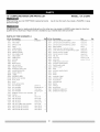
10" COMPOUND
MITER SAW PARTS LIST
MODEL:
When servicing use only CRAFTSMAN replacement parts.
product damage.
137.212540
Use of any other parts may create a HAZARD or cause
Any attempt to repair or replace electrical parts on this miter saw may create a HAZARD unless repair is done by a
qualified service technician. Repair service is available at your nearest Sears Service Center.
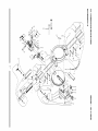
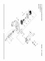
PARTS LIST FOR SCHEMATIC A
I.D. No. Description
2457
Size
FLAT WASHER
@10x22-2
qty
2
I,D,
No,
0K2W
Description
HEX.SOCKET
HD.CAP
SCREW
Size
M5xO.8-16
Qty
2
0810
ARM-MITER
1
OK7F
CR. RE. ROUND
WASHER
HD. SCREW
M5xO.8-8
8
0813
SPRING
1
0K7K
CR. RE. ROUND
WASHER
HD. SCREW
M6x] .0-12
4
0817
TABLE
1
OK9X
DRIVE SCREW
@2.3-5
2
0819
MITER HANDLE
1
0KB5
CR.RE.
M4X18-10
4
081A
PLASTIC SLEEVE
1
0KCX
CR. RE. PAN HD PLAIN WASHER TAPPING SCREW
M5xO.8-10
5
081D
NEEDLE POINTER
1
0KDL
CR. RE. PAN HD. SCREW
M5xO.8-18
2
081G
FOLLOWER
5
0KDR
CR. RE. PAN HD. SCREW
M5xO.8-10
3
081J
TABLE INSERT
1
0KMS
HEX. NUT
M6x1.0
081L
MITER SCALE
1
0KQZ
LOCK
NUT
MIOx1.5
081V
SUPPORT
1
OKR0
LOCK
NUT
M12x1.75
0820
FENCE
1
OS2T
MITER QUICK
0822
BEVEL SCALE
1
OS2V
0825
HEX. HD. BOLT
1
OSTZ
TRADE-MARK
0827
NEEDLE POINTER
2
202E
SAFETY CLAMP
0828
ROTATION
1
203Y
BASE
082F
ANGLE
1
20S3
LOCKING
082G
SLIDING
1
20X3
KNOB
082W
LABEL
21DZ
KNOB
084W
WARNING
1
1
22SL
AUXILIARY
OCQH
BEVEL LOCK
22SN
LOCKING
OD7W
STOP LATCH
22SP
SCALE
OD7X
SHAFT
22SR
SUPPORT
0D7Z
STOP LATCH
PLATE
PLATE
SLIDE PLATE
REGULATOR
FENCE
LABEL
HANDLE
KNOB
22SW
PAN HD. TAPPING
LOCKING
LOCK
HANDLE
HANDLE
ASS'Y
8
2
TABLE
TUBE
PLATE
ROD
FLAT WASHER
@6x18-1.5
FLAT WASHER
3/8x29/32-1/8
1
22T3
STOP BLOCK
0J7R
FLAT WASHER
1/2xl-3/54
1
235C
EXTENSION
TABLE ASS'Y
0J8D
FLAT WASHER
3/8x3/4-5/54
1
24F2
EXTENSION
TABLE ASS'Y
0JAF
EXTERNAL
@5
2
WASHER
O-RING
P5
1
OJPD
HEX. HD. BOLT
M6x1.0-16
1
OJPE
HEX. HD. BOLT
M6x1.0-20
1
OJQM
HEX. HD. BOLT
M6x1.0-30
2
0JQT
HEX. HD. BOLT
OJMM
0K0W
HEX. HD. SCREW
AND
WASHER
M10x1.5-75
1
M6x1.0-25
2
2
0K24
HEX.SOCKET
HD.CAP
BOLT
M8x1.25-35
0K2N
HEX.SOCKET
HD.CAP
BOLT
M8x1.25-25
1
0K2S
HEX.SOCKET
HD.CAP
BOLT
M8x1.25-45
2
2
2
4
4
2
OJ4U
LOCK
T=12
ASS'Y
OJ7G
TOOTH
T=10
LABEL
2
HANDLE
T=5
ASS'Y
FENCE
22SX
SCREW
t'}
o
r'rl
{"}
o
0
\
:_
C
z
228!
m
,-I
I1"1
t_
O_QT
2(}8_
b.}
--a
\
\
I
X
x
c
\
\
0
0
I1"1
r¢,€
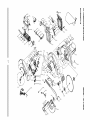
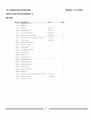
10" COMPOUND
MITER SAW
MODEL: 137.212540
PARTS LIST FOR SCHEMATIC B
I.D. No.
2145
Size
Description
LOCK HANDLE
ASS'Y
COLOR
#23
Qty
1
I.D. No.
0gEM
1
0JET
E-RING
1
0JFB
SELF-LOCKING
1
0JMQ
2146
LASER ASS'Y
2794
TRADE-MARK
0831
SHAFT SLEEVE
0833
LEVER
1
0836
PC-GUARD
083S
TRIGGER
083V
LABEL
COLOR
#6
Description
C-RING
E-4
RING
SPN-5
O-RING
P8
OJUK
HEX. SOC.
HD. CAP
1
0JZF
HEX. SOC.
SET SCREW
1
OJZN
ARBOR
HANDLE(RIGHTSIDE)
1
0K29
HEX.SOCKET
083X
BUTTON SWITCH
1
0K42
CR.RE. PAN
083Y
COMPRESSION
1
0K72
CR.-RE. TRUSS HD. SCREW
083Z
CORD
1
0K7Z
CR. RE. TRUSS HD. ROUND
0841
HANDLE
(LEFT SIDE)
1
0KA6
CR.RE. PANHD.
084C
HANDLE
SEAT
1
OKB7
084D
CARRY
HANDLE
1
SPRING
CLAMP
Qty
Size
A-34
BOLT
M6x1.0-16
M6x1.0-10
BOLT
M8x1.25-20
HD.CAP
SCREW
HD. SCREW
M6x1.0-12
& WASHER
M6x1.0-30
MBx0.8-12
NECK
SCREW
M6x1.0-14
TAPPING
SCREW
M5x12-10
CR.RE. PAN
HD. TAPPING
SCREW
M4xl
OKB8
CR.RE. PAN
HD. TAPPING
SCREW
M4x18-20
HD. TAPPING
8-16
084F
HANDLE
1
OKB9
CR.RE. PAN
084H
BOLT
1
0KBC
CR.RE. PANHD.
084J
CUSHION
1
OKBM
CR.RE. PAN
084K
SET PLATE
1
0KD6
CR. RE. PAN HD. SCREW
M4x0.7-8
084M
STOP CLAMP
1
OKMS
LOCK
NUT
M6xl.0T=5
084Q
COMPRESSION
084S
LOCKING
LEVER
SCREW
M5x16-10
TAPPING
SCREW
M5x16-25
HD. TAPPING
SCREW
M4x18-28
1
0KQW
LOCK
NUT
M5x0.8
TILTING SCALE
1
0KQY
LOCK
NUT
M8x1.25
084V
ELBOW
1
0KR3
LOCK
NUT
M6x1.0
1
0KTT
WIRE CLAMP
1
OKUX
TERMINAL
SPRING
0859
TENSION
085C
FOLLOWER
PLATE
085D
SLIDE PLATE
1
0KWT
LEAD
085E
SPACER
1
0L8A
POWER
085G
PLATE COVER
1
0LU2
LIMIT SWITCH
085H
HANDLE
1
OQN0
MOTOR
085J
HANDLE
1
OQQ1
GUARD-CORD
OBD1
CUSHION
1
OS2W
HOUSING
OCES
COMPRESSION
1
OS2X
LOCK
0CKS
SPRING
1
OSTZ
TRADE-MARK
1
20KY
TORSION
1
20LM
TRADE-MARK
1
20LU
CAUTION
1
21EF
SPRING
1
23PP
BLADE
PLATE
BAR
SPRING
WIRE
OCV5
DUST BAG
0D99
SHIM
0D9A
ANCHOR
OD9S
CHIP
ODT4
ROLLING
ASS'Y
BLOCK
PLATE
WHEEL
COLOR
#6
COLOR
#6
"1/4 ......
CABLE
ASS'Y
HANDLE
ASS'Y
LABEL
SPRING
LABEL
LABEL
GUARD
BEARING
1
24HS
LABEL
ODTZ
ARBOR
COLLAR
2
25AZ
CAUTION
ODVJ
BLADE
WRENCH
1
26LR
WARNING
0J53
FLAT WASHER
cp8.4x24-2
1
272Y
BOLT
0J6G
FLAT WASHER
cp8.2x18-2.0
1
0JB3
WAVE
WW-14
1
0JBZ
PARALLEL
cp6.0-16
1
2439
INSTRUCTION
PIN
T=8
T=6
WIRE ASS'Y
ODT7
WASHER
T=5
LABEL
LABEL
MANUAL
1
:I:
Ill
Ill
O_tv5
¢'}
C
z
0
.-I
m
24}t5
[
(I)
04K
_D
25!Z
21}
0
0
m
r-
OKTZ
0833
0D74
',,,i
i,}
10" COMPOUND
MITER SAW
PARTS LIST FOR SCHEMATIC
MODEL: 137.212540
C
MOTOR
I.D. No.
1100
Description
GEAR BOX COVER
1101
UPPER ARM
1102
SPRING
Size
Qty
1
1
PIN
cp4-36
1
0HX9
NEEDLE BEARING
HK-1010
1
0JX2
HEX.-SOC
M5xO.8-6
2
0K56
CR. RE. COUNT
M5x0.8-12
3
M5x 16-35
4
M5xO,8-6
2
OKCM
OKLA
OKWM
0PLT
SET SCREW
CR.-RE.PAN
HD. SCREW
HD, AP, SCREW
& WASHER
PLASTIC SCREW
LEAD WtRE ASS'Y -RED
1
BEARING
1
COVER
OQ9K
FLOW GUIDE
1
OQGR
COMPRESSION
OQME
BRACKET
0QMK
PLASTIC CAP
OQMR
ARMATURE
0QMY
WIRE PROTECTOR
0QQS
BRUSH HOLDER
OQQU
CARBON
SPRING
1
STOP
1
1
ASS'Y
-
1
1
ASS'Y
2
BRUSH ASS'Y
2
OQRO
BRUSH COVER
2
OQR2
BEARING
1
BUSHING
OQYW
FIELD ASS'Y
110A
CR. RE.PAN
1 lOB
MOTOR
110C
ARBOR
1
HD.TAPPtNG
HOUSING
SHAFT ASS'Y
SCREW
& WASHER
M5x 12-55
2
COLOR
1
23#
1
o
o
0
0
C
z
0
m
.-I
ITI
(I)
/
0
0
m
po0
f,o
ol
o
10" COMPOUND
MITER SAW
MODEL: 137.212540
PARTS LIST FOR SCHEMATIC
D
STAND
I.D.
No.
093B
Description
RUBBER FOOT
0J4F
FLAT WASHER
0KRR
SERRATED
OSTZ
TRADE-MARK
OZlG
CAP
TOOTHED
LONG
22XV
SHORT
22XW
LONG
22XX
SHORT
22XY
23A9
color
HEXAGON
FLANGE
NUT
#6
4
cp8x ] 6-2.5
3
M8x]
19
.25 T=7.5
LABEL
HD. SQ.NECK
22XS
Qty
SJze
PAD
1
BOLT
M8x ] .25-12
16
UPPER SUPPORT
color
#6
2
UPPER SUPPORT
color
#6
2
BOTTOM
SUPPORT
BRACKET
color
#6
2
SUPPORT
BRACKET
color
#6
2
BRACKET
color
#6
4
CR. RE. PAN HD. SCREW
M8x1.25-25
BOTTOM
3
10" COMPOUN D MITER SAW
SCHEMATIC
MODEL: 137.212540
D
STAND
........ _fA9
..............
OJ4[
22XS
OZl (;
22XX
22XY
093B
;}fffffffffffffffffffffffffffffffffffffffffffffffffffffffffffffffffffffffffffffff
ZZ
Your Home
For repair - in your home - of all major brand appliances,
lawn and garden equipment, or heating and cooling systems,
no matter who made it, no matter who sold it!
For the replacement parts, accessories and
Operator's Manuals that you need to do-it-yourself.
For Sears professional installation of home appliances
and items like garage door openers and water heaters.
1-800-4-MY-HOME ® (1-800-469-4663)
Call anytime, day or night (U.S.A. and Canada)
www.sears.com
www.sears.ca
Our Home
For repair of carry-in items like vacuums, lawn equipment,
and electronics, call or go on-line for the location of your nearest
Sears Parts & Repair Center.
1-800-488-1222
Call anytime, day or night (U.S.A. only)
www.sears.com
To purchase a protection agreement (U.S.A)
or maintenance agreement (Canada) on a product serviced by Sears:
1-800-827-6655
(U.S.A.)
1-800-361-6665
(Canada)
Para pedir servicio de reparaci6n
a domicilio, y para ordenar piezas:
1-888-SU-HOGAR sM
(1-888-784-6427)
Au Canada pour service en fran(_ais:
1-800-LE-FOYER Mc
(1-800-533-6937)
www.sears.ca
,_,gE/.4R8
® Registered Trademark / TM Trademark / SM Service Mark of Sears, Roebuck and Co.
® Marca Registrada / TM Marca de Fabrica / sM Marca de Servicio de Sears, Roebuck and Co.
MC Marque de commerce / ' Marque depos6e de Sears, Roebuck and Co.
© Sears, Roebuck
and Co.