1
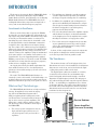
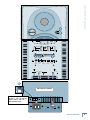
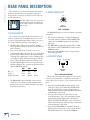
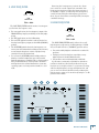
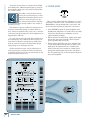
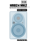
HR624 MK2 High Resolution Active Studio Monitor OWNER’S MANUAL HR624 MK2 IMPORTANT SAFETY INSTRUCTIONS 1. Read these instructions. 13.Unplug this apparatus during lightning storms or when unused for long periods of time. 2. Keep these instructions. 3. Heed all warnings. 4. Follow all instructions. 5. Do not use this apparatus near water. 6. Clean only with dry cloth. Use a non-scratch cloth to protect the finish. 7. Do not block any ventilation openings. Install in accordance with the manufacturer’s instructions. 8. Do not install near any heat sources such as radiators, heat registers, stoves, or other apparatus (including amplifiers) that produce heat. 9. Do not defeat the safety purpose of the polarized or grounding-type plug. A polarized plug has two blades with one wider than the other. A grounding-type plug has two blades and a third grounding prong. The wide blade or the third prong are provided for your safety. If the provided plug does not fit into your outlet, consult an electrician for replacement of the obsolete outlet. 10.Protect the power cord from being walked on or pinched particularly at plugs, convenience receptacles, and the point where they exit from the apparatus. 11.Only use attachments/accessories specified by the manufacturer. 12.Use only with a cart, stand, tripod, bracket, or table specified by the manufacturer, or sold with the apparatus. When a cart is used, use caution when moving the cart/apparatus combination to avoid injury from tip-over. CAUTION PORTABLE CART WARNING AVIS RISK OF ELECTRIC SHOCK. DO NOT OPEN RISQUE DE CHOC ELECTRIQUE. NE PAS OUVRIR CAUTION: TO REDUCE THE RISK OF ELECTRIC SHOCK DO NOT REMOVE COVER (OR BACK) NO USER-SERVICEABLE PARTS INSIDE. REFER SERVICING TO QUALIFIED PERSONNEL ATTENTION: POUR EVITER LES RISQUES DE CHOC ELECTRIQUE, NE PAS ENLEVER LE COUVERCLE. AUCUN ENTRETIEN DE PIECES INTERIEURES PAR L'USAGER. CONFIER L'ENTRETIEN AU PERSONNEL QUALIFIE. AVIS: POUR EVITER LES RISQUES D'INCENDIE OU D'ELECTROCUTION, N'EXPOSEZ PAS CET ARTICLE A LA PLUIE OU A L'HUMIDITE The lightning flash with arrowhead symbol within an equilateral triangle is intended to alert the user to the presence of uninsulated "dangerous voltage" within the product's enclosure, that may be of sufficient magnitude to constitute a risk of electric shock to persons. Le symbole éclair avec point de flèche à l'intérieur d'un triangle équilatéral est utilisé pour alerter l'utilisateur de la présence à l'intérieur du coffret de "voltage dangereux" non isolé d'ampleur suffisante pour constituer un risque d'éléctrocution. The exclamation point within an equilateral triangle is intended to alert the user of the presence of important operating and maintenance (servicing) instructions in the literature accompanying the appliance. Le point d'exclamation à l'intérieur d'un triangle équilatéral est employé pour alerter les utilisateurs de la présence d'instructions importantes pour le fonctionnement et l'entretien (service) dans le livret d'instruction accompagnant l'appareil. 14.Refer all servicing to qualified service personnel. Servicing is required when the apparatus has been damaged in any way, such as powersupply cord or plug is damaged, liquid has been spilled or objects have fallen into the apparatus, the apparatus has been exposed to rain or moisture, does not operate normally, or has been dropped. 15.This apparatus shall not be exposed to dripping or splashing, and no object filled with liquids, such as vases, shall be placed on the apparatus. 16.Note that this apparatus is not completely disconnected from the AC mains service when the power switch is in the OFF position. 17.The MAINS plug or an appliance coupler is used as the disconnect device, so the disconnect device shall remain readily operable. 18.Exposure to extremely high noise levels may cause permanent hearing loss. Individuals vary considerably in susceptibility to noise-induced hearing loss, but nearly everyone will lose some hearing if exposed to sufficiently intense noise for a period of time. The U.S. Government’s Occupational Safety and Health Administration (OSHA) has specified the permissible noise level exposures shown in the following chart. According to OSHA, any exposure in excess of these permissible limits could result in some hearing loss. To ensure against potentially dangerous exposure to high sound pressure levels, it is recommended that all persons exposed to equipment capable of producing high sound pressure levels use hearing protectors while the equipment is in operation. Ear plugs or protectors in the ear canals or over the ears must be worn when operating the equipment in order to prevent permanent hearing loss if exposure is in excess of the limits set forth here. Duration, per day in hours 8 6 4 3 2 1.5 1 Sound Level dBA, Slow Response 90 92 95 97 100 102 105 0.5 110 0.25 or less 115 Typical Example Duo in small club Subway Train Very loud classical music Dave screaming at Steve about deadlines Loudest parts at a rock concert WARNING — To reduce the risk of fire or electric shock, do not expose this apparatus to rain or moisture. Correct disposal of this product. This symbol indicates that this product should not be disposed of with your household waste, according to the WEEE Directive (2002/96/EC) and your national law. This product should be handed over to an authorized collection site for recycling waste electrical and electronic equipment (EEE). Improper handling of this type of waste could have a possible negative impact on the environment and human health due to potentially hazardous substances that are generally associated with EEE. At the same time, your cooperation in the correct disposal of this product will contribute to the effective usage of natural resources. For more information about where you can drop off your waste equipment for recycling, please contact your local city office, waste authority, or your household waste disposal service. HR624 MK2 Thank you for choosing the Mackie HR624 MK2 Studio Monitors. We began producing the original HR624 Studio Monitors in 2001, the baby brother to our flagship HR824 Studio Monitors. The HR624 MK2s have been redesigned with modern components for improved accuracy and an extended low-frequency response. Investments in Excellence... When we decided it was time to update the HR624s, we turned to our expert loudspeaker and transducer design engineering team at EAW to determine how to make an already excellent studio monitor even better. The first thing they noticed was that the front baffle could be redesigned with a rounder aluminum construction to further reduce edge diffraction for improved imaging. The volume of the cabinet was increased slightly to improve the low-frequency response. The amplifiers have been adjusted with all new ‘voicing’ to match the new cabinets. However, the amplifiers’ design is fundamentally the same and has a very similar characteristic to the original model. If you are upgrading from the original HR624s, you won’t have to relearn the sound. The MK2s still deliver the clarity, ultra-linear frequency response, and broad stereo imaging of the originals. An elegant piano-black gloss finish emphasizes that these studio monitors are in a class by themselves, pleasing to the most discerning eye as well as the most discerning ear. The result? The HR624 MK2 Studio Monitors are extremely accurate and versatile, loaded with unique controls that allow you to fine-tune the sound to match your individual environment precisely. You’re gonna love these! What are they? The Advantages... • The crossover point is designed so that the high- and low-frequency drivers are fed only the frequencies they are best able to reproduce. Woofer Tweeter The HR624 MK2 Studio Monitors are high-resolution, two-way, bi-amplified, active monitors employing a 6th-order Butterworth system with a built-in rear-firing mass-loaded passive radiator. Whew! There are many benefits to integrating an active crossover, power amplifiers, and drivers into a single cabinet, and we’ve taken full advantage of these benefits in the design of the HR624 MK2. • The amplifiers are designed to provide maximum acoustic output from the speakers, yet minimize the danger of speaker damage due to overdriving. • In addition, the amplifiers’ gain and frequency responses are individually hand-trimmed to compensate for typical manufacturing tolerances between the drivers and produce a smooth frequency response from 45 Hz to 20 kHz. Owner’s Manual INTRODUCTION • The connecting wires between the amplifier outputs and the drivers are kept to an absolute minimum, so the damping factor of the amplifier isn’t compromised by the resistance of long speaker cables. • The acoustic sum of the outputs from the two drivers are optimized electronically, as well as physically, so the amplitude response is unity and the phase difference is minimal. In short, all the complex interconnected components in the system are designed to work in harmony with each other to produce the best possible sound. The Transducers... The monitors feature a 6.7-inch high-precision, lowdistortion woofer and a 1-inch ferrofluid cooled titanium dome tweeter on the front, and a 6-inch x 9-inch elliptical flat piston passive radiator in the back. The high-frequency driver is mounted on a massive, acoustically non-resonant die-cast aluminum exponential waveguide, which results in wide, controlled dispersion of high-frequency sounds. The unique passive radiator design provides a smooth response down to 45 Hz — an astounding accomplishment for a cabinet of this size! And since the radiator is producing most of the sound at the lowest frequencies, there is very little distortion from the woofer because its cone movement is minimal at those frequencies. Passive Radiator Power Amplifier/ Crossover Assembly Figure 1. HR624 MK2 Cutaway side view Owner’s Manual HR624 MK2 The Cabinet... The cabinet is made of MDF with a high-gloss pianoblack finish. Internal bracing increases the strength and rigidity (stiffness) of the box. An open-cell adiabatic foam material fills the inside of the box to absorb internal reflections and dampen standing waves. Mounting hardware is installed on the bottom of the cabinet that fits the WB-60 OmniMount wall-mount bracket. Power Amplifiers... The low-frequency amplifier produces up to 100 watts continuous before clipping, while the high-frequency amplifier produces up to 40 watts continuous. QUICK START We realize that you can’t wait to hook up your new Mackie HR624 MK2 High Resolution Studio Monitors and try them out. Nevertheless, please take the time to read this page NOW, and the rest can wait until you’re good and ready. Make sure the Voltage Selector Switch [11] on the bottom of the cabinet is set to the correct voltage setting for your AC Mains supply. Each of the HR624 MK2 cabinets has its own builtin power amplifiers. That’s right, two amplifiers per speaker cabinet; one for the high-frequency tweeter and one for the low-frequency woofer. You should turn the INPUT SENSITIVITY [2] control on the back of the cabinet down (fully counterclockwise) before turning on the Studio Monitors for the first time. Also be sure to set the power switch [9] on the front panel to its standby position (out). This will prevent you from accidentally connecting a hot signal source to the monitors and getting a rude surprise. There are a number of other settings you can make on the back of the HR624 MK2, and you can look at the graphic instructions relating to each of them on the back of the cabinet (or wait until you read about them later on in this manual so you really know what they do). For now, just leave them at the factory default settings (ACOUSTIC SPACE = WHOLE; LOW FREQ = 49Hz; HIGH FREQ = 0), except for the POWER MODE [6] switch. Be sure it is set to the STANDBY position. HR624 MK2 1. Connect the line-level monitor signal from your mixer, preamp, or other signal source to the SIGNAL INPUT [1] jack on the HR624 MK2 Studio Monitor (1⁄4-inch PHONE, XLR, or RCA). 2. Connect the supplied AC power cord to the IEC socket [7] on the back of the monitor. Plug the other end into an AC outlet properly configured with the voltage corresponding to the Voltage Selector Switch [11] setting. 3. Set the POWER MODE [6] switch on the rear panel to the ON position. With the front panel power switch [9] out, the power amplifier is in Standby mode. 4. Start your signal source (tape deck, CD, DAW, or whatever), but leave the master volume control on your mixer or preamp down. 5. Push in the power switch [9] on the front of the HR624 MK2. The power ring [10] around the switch will illuminate. 6. Slowly turn up the INPUT SENSITIVITY [2] control on the back of the monitor to its fully clockwise position (NORMAL). 7. Adjust the master volume on your mixer to a comfortably loud listening level. Enjoy the silky smooth highs and authoritative, commanding lows of the HR624 MK2. Then read the rest of this manual. AN EXTREMELY IMPORTANT NOTE ON HR624 MK2 BASS RESPONSE AND YOUR CONTROL ROOM. Your new HR624 MK2s achieve their best bass response in a room that’s optimized for bass reproduction. A lot of factors can conspire to thwart the HR624 MK2s’ extended low frequency — including room shape, room volume and acoustical treatment. This is not a cop-out or an apology. It’s plain old physics in action. Luckily we’ve armed you with some compensating controls that you can use to optimize the frequency response of the speakers in your particular room. Consider the following: The ACOUSTIC SPACE switch must be set correctly. When you put your HR624 MK2s in a corner or up against walls, their bass characteristics change. Adjust the ACOUSTIC SPACE [3] switch setting accordingly to avoid muddy or exaggerated low frequency response. Owner’s Manual QUARTER SPACE HALF SPACE CONSOLE CONSOLE SPEAKERS IN CORNERS SPEAKERS AGAINST WALL SPEAKERS AWAY FROM WALLS B C WHOLE SPACE CONSOLE A ACOUSTIC SPACE APPLICATIONS 49Hz 10kHz 0dB LOW CUT 0dB + 2dB –2dB –4dB –3dB 80Hz 0dB – 2dB 20 LOW FREQ 100Hz ACOUSTIC SPACE HIGH FREQ WARNING: TO REDUCE THE RISK OF FIRE OR ELECTRIC SHOCK, DO NOT EXPOSE THIS EQUIPMENT TO RAIN OR MOISTURE. DO NOT REMOVE COVER. NO USER SERVICEABLE PARTS INSIDE. REFER SERVICING TO QUALIFIED PERSONNEL. RISK OF ELECTRIC SHOCK DO NOT OPEN –10dB OFF AVIS: RISQUE DE CHOC ELECTRIQUE — NE PAS OUVRIR QUARTER WHOLE (NORMAL) A C NORMAL B HALF INPUT SENSITIVITY 80Hz 49Hz LOW CUT (NORMAL) ACOUSTIC SPACE LOW FREQ FILTER –2dB 0 +2dB STANDBY (NORMAL) AUTO ON HIGH FREQ FILTER POWER MODE SIGNAL INPUTS BAL/UNBAL PHONE XLR ON MAINS INPUT RCA BOTTOM OF CABINET 120 Set the Voltage Selector Switch to “120” for 120 VAC mains, and to “240” for 220-240 VAC mains. Owner’s Manual HR624 MK2 Feel free to experiment. Placement In many respects, every room is unique in terms of its acoustics. The HR624 MK2s were designed to be placed in a vertical position. If you find it necessary to place the speakers in a horizontal position (on their sides), place them so that the woofers are toward the inside; that is, so the woofers are closest to each other. This provides the best low-frequency summing and overall imaging. Even after you’ve read about how to set the HR624 MK2’s rear panel switches, try other settings to see if your particular room environment requires different adjustments. And, even after you’ve placed your monitors where you think they’ll sound best, try moving them around. You might be pleasantly surprised. Finally, keep an open mind about improving your room’s acoustics and bass-handling ability. Nobody likes to buy a new set of monitor speakers and then be told that they should spend extra bucks on bass traps or a remodeling job. But the simple fact is, “standard” rooms, i.e., rectangular rooms in conventional business or residential structures, are rarely if ever conducive to optimal low bass reproduction without some modifications. Luckily, there are plenty of options short of building a new control room, many of which are covered in this manual. Additional Tidbits of Wisdom • When you shut down your equipment, turn off the HR624 MK2 studio monitors first to prevent thumps and other noises generated by any upstream equipment from coming out the speakers. When powering up, turn on the monitors last. • Save the shipping box! You may need it someday, and you don’t want to have to pay for another one. • Save your sales receipt in a safe place. • Also record all HR624 MK2 serial numbers in the space provided on the next page, along with where and when you bought them. HR624 MK2 The HR624 MK2s can also be wall-mounted using the mounting hardware located on the bottom of the cabinet. This is designed to be used with the OmniMount 30.0 WB (Wall-to-Bottom) wall-mount bracket, which provides a wide range of horizontal and vertical movement to meet your coverage requirements. Refer to the OmniMount website for more details. www.omnimount.com/pro A Few Words About THX™ pm3™ Certification Nearly two decades ago, George Lucas turned a passion for great sound into the world’s most accepted and trusted solution for achieving it. The standard was named THX (for Tomlinson Holman, who developed the THX Sound System when he was the research and technical director at Lucasfilm Ltd.™ in the early 80s), and today, with hundreds of thousands of home theater customers and more than 3000 THX Certified movie theaters enjoying its benefits, the THX name has become nothing short of legendary. Simply put: when it comes to premium sound, no other name so closely defines ‘quality’ for millions of movie-goers and home theater enthusiasts alike. Today, a new landscape is emerging. A landscape comprised of hundreds of small, professional multi-channel facilities, whose need for differentiation, expert technical and marketing support, and a true, multi-channel Note: The Mackie logo can be rotated 90º so that it is oriented correctly when placing the speakers on their sides. Gently pull out on the Mackie emblem, rotate it, and push it back into place. Contents All facilities involved with mixing and/or monitoring of multi-channel material should have the option to use pm3. THX pm3 Certification is ideal for DVD mastering, sweetening, and mixing; and is also perfect for facilities doing work in broadcast, music, or multi-media applications. IMPORTANT SAFETY INSTRUCTIONS............2 INTRODUCTION.................................................. 3 HR624 MK2 THX pm3 Certification When we submitted the HR624 MK2s for THX pm3 Certification, they passed on the first try with no modifications! Anyone seeking THX Certification for their studio, or striving to maintain THX standards, can use the HR624 MK2s and rest assured that their facility is in full compliance. QUICK START............................................................................ 4 REAR PANEL DESCRIPTION ..............................8 1. SIGNAL INPUTS................................................................ 8 2. INPUT SENSITIVITY......................................................... 8 3. ACOUSTIC SPACE............................................................. 8 4. LOW FREQ FILTER............................................................ 9 5. HIGH FREQ FILTER........................................................... 9 6. POWER MODE................................................................10 7. Mains Input......................................................................10 8. Passive Radiator..............................................................11 Owner’s Manual standard is becoming a competitive fact of life. Again, THX has a singular solution and this time it’s called THX pm3 Certification. FRONT PANEL DESCRIPTION...........................12 9. Power Switch...................................................................12 10. Power Ring and Overload Indicator.......................12 PROTECTION CIRCUITS.....................................12 Overload Protect ..............................................................12 Thermal Protect.................................................................. 13 Integrated Magnetic Shielding....................................... 13 Input Signal Wiring............................................................ 13 CARE AND CLEANING........................................13 SERVICE INFO.......................................................14 Troubleshooting.................................................................14 Repair.....................................................................................15 TECHNICAL INFORMATION............................ 16 HR624 MK2 Specifications..................................................16 Graphs....................................................................................17 HR624 MK2 Block Diagram..............................................18 • Please write the serial number for your studio monitor here (all studio monitors if you have more than one) for future reference (i.e., insurance claims, tech support, return authorization, etc.): Monitor 3 Monitor 1 Monitor 2 Purchased at:___________________________________ Date of Purchase:_____________ Part No. SW0592 Rev. D 01/09 ©2007-2009 LOUD Technologies Inc. All Rights Reserved. Owner’s Manual HR624 MK2 REAR PANEL DESCRIPTION This is where you connect your signal to the monitor, and make adjustments to the frequency response of the speakers to match the monitor’s location and your room’s environment. 2. INPUT SENSITIVITY –10dB For THX applications, the rear panel switches and controls should be set to the THX positions as indicated in this section. OFF QUARTER WHOLE (NORMAL) A C NORMAL 80Hz B HALF INPUT SENSITIVITY 49Hz LOW CUT ACOUSTIC SPACE (NORM LOW FREQ FILTER THX = NORMAL 1. SIGNAL INPUTS The HR624 MK2 expects a line-level signal at its input connectors. The location of the signal input jacks makes the connectors exit down and not straight out the back of the enclosure. This flush-mount design allows you to place the monitor right up against the wall if desired. • The XLR female, TRS female (balanced), and RCA female (unbalanced) input connectors are provided for user convenience. • Don’t connect more than one source to the jacks. • Unbalanced TS (tip-sleeve) lines can be accommodated via the TRS jack. Make sure the cable terminates with a TS plug (like a guitar plug), or if it’s a TRS plug (such as a headphone plug), make sure the ring is tied to the sleeve and that the plug is fully inserted into the jack. • The XLR and TRS input connectors accept balanced or unbalanced signals. The connectors are wired as follows (per the AES/IEC standard): XLR TRS RCA Hot (+) Cold (–) Shield (Ground) Pin 2 Pin 3 Pin 1 Tip Ring Shield Tip — Shield • The HR624 MK2s can be used with a home receiver even if the receiver lacks a preamp output by using a speaker-level to line-level signal attenuator. (See page 13 for more information.) HR624 MK2 • The reference sensitivity is –7.5 dBu=100 dB SPL at one meter (39 inches) with the INPUT SENSITIVITY control set to its NORMAL position (in other words, wide open). • The HR624 MK2 is designed to operate with a +4 dBu signal when the INPUT SENSITIVITY control is in the NORMAL position. • Refer to the QUICK START section on page 4 for the level-setting procedure. 3. ACOUSTIC SPACE –10dB OFF NORMAL QUARTER WHOLE (NORMAL) A C B HALF INPUT SENSITIVITY ACOUSTIC SPACE 80Hz 49Hz LOW CUT (NORMAL) –2dB LOW FREQ FILTER THX = WHOLE (NORMAL) This is a three-way switch that adjusts the low-frequency response of the monitors to compensate for their placement in the room. See page 5 for an overview of the rear panel. • If you place the HR624 MK2 monitors against a wall (half space [3B]), set the ACOUSTIC SPACE switch to the “B” position. This activates a shelving filter to reduce the low-frequency output by 2 dB to compensate for the half-space placement. • If you place the monitors into the corners of your room (quarter space [3A]), the low-frequency output approximately doubles from what it is in half space. Set the ACOUSTIC SPACE switch to the “A” position to reduce the low-frequency output by 4 dB to compensate for the quarter-space placement. • If you use the HR624 MK2s free-standing, away from walls and corners (whole space [3C]), set the ACOUSTIC SPACE switch to the “C” position (NORMAL). 0 +2dB (NORMAL) HIGH FREQ FILTER NORMAL INPUT SENSITIVITY 4. LOW FREQ FILTER QUARTER WHOLE (NORMAL) A C B HALF ACOUSTIC SPACE –2dB 80Hz 49Hz LOW CUT (NORMAL) +2dB 0 (NORMAL) LOW FREQ FILTER HIGH FREQ FILTER THX = 80Hz–10dB Removing the low-frequency content also allows you to raise the overall output level somewhat. Lowfrequency information requires the largest amount of an amplifier’s output, so restricting the low-frequency allows raising the mid-frequency level someSTANDBY content ON AUTO what. If your client insists on mixing LOUD, this may be ON a workable strategy. POWER MODE 5. HIGH FREQ FILTER QUARTER WHOLE (NORMAL) A C The LOW FREQ FILTER switch inserts a low-frequency rolloff into the response curve. OFF NORMAL 80Hz B 49Hz –2dB 0 +2dB STANDBY ON • For some applications, the low-frequency output of the (NORMAL) LOW CUT (NORMAL) AUTO HALF ON HR624 MK2 may impair your ability to make mix judgeINPUT ACOUSTIC LOW HIGH POWER ments. SENSITIVITY SPACE FREQ FILTER FREQ FILTER MODE • For THX applications, use the 80Hz setting. THX = 0 dB • For non-THX applications where a sub-woofer isn’t enhancing low-frequency output use the 49Hz (NORMAL) The HIGH FREQ FILTER switch tailors the overall position. high-frequency response by ±2 dB beginning at 10kHz. Leave this switch in the 0 (NORMAL) position unless: • The LOW FREQ switch affects the low-frequency content of your mix. Remember how things work in reverse, to subtly brighten or darken the sound of the SPACE SPACE so removing the deep bass content QUARTER on playback may HALF SPACE• You want WHOLE speakers. CONSOLE actually increase it in the final mix. CONSOLE CONSOLE • Perhaps you have hearing loss caused by too many • You can use the LOW FREQ switch’s 80Hz position to nights in front of a double Marshall stack. simulate a smaller loudspeaker, especially one with A B • You just likeCto mix on the bright side or dull side. limited low-frequency capability (like a certain popular ACOUSTIC SPACE APPLICATIONS If your mixes consistently sound dull or dark when 2-way nearfield monitor). You may need to do this if a you listen elsewhere, this usually indicates that your small speaker is the eventual destination of your mix, 0 monitors 02are too bright, relative to your normal hearing. 0 or perhaps just to see how your –mix sounds on a clock –2 3 –4 A bit less–2high-frequency energy usually fixes this, and radio. you can force the mix in this direction by reducing the LOW FREQ ACOUSTIC SPACE HIGH FREQ high-frequency output of the monitors by using the –2 dB position of the switch. SPEAKERS IN CORNERS SPEAKERS AWAY FROM WALLS SPEAKERS AGAINST WALL LOW CUT 10kHz dB dB dB + dB dB dB dB 49Hz 80Hz Owner’s Manual OFF –10dB dB 20 100Hz WARNING: TO REDUCE THE RISK OF FIRE OR ELECTRIC SHOCK, DO NOT EXPOSE THIS EQUIPMENT TO RAIN OR MOISTURE. DO NOT REMOVE COVER. NO USER SERVICEABLE PARTS INSIDE. REFER SERVICING TO QUALIFIED PERSONNEL. RISK OF ELECTRIC SHOCK DO NOT OPEN –10dB OFF AVIS: RISQUE DE CHOC ELECTRIQUE — NE PAS OUVRIR QUARTER WHOLE (NORMAL) A C NORMAL B HALF INPUT SENSITIVITY 80Hz 49Hz LOW CUT (NORMAL) ACOUSTIC SPACE LOW FREQ FILTER SIGNAL INPUTS BAL/UNBAL PHONE XLR –2dB 0 +2dB STANDBY (NORMAL) AUTO ON HIGH FREQ FILTER POWER MODE ON MAINS INPUT RCA Owner’s Manual HR624 MK2 Conversely, if your mixes are consistently too bright, QUARTER WHOLE (NORMAL) –10dB then adding some additional high-frequency energy in A C the monitors satisfies your ears, and the resultant mix has less HF content. OFF NORMAL 80Hz 49Hz –2dB 0 +2dB STANDBY ON B The timbre of your monitors affects (NORMAL) LOW CUT (NORMAL) AUTO HALF ON the way that your mixes play on other INPUT ACOUSTIC LOW HIGH POWER equipment. Remember SENSITIVITY SPACE that the moniFREQ FILTER FREQ FILTER MODE tors have a mirroring effect on the This 3-position switch turns the amplifiers on or off, or mix; if the monitors make something sets them to automatic mode. Use this switch to set the too loud in the mix it usually results in not enough of HR624 MK2s to your preferred mode of operation, and that thing on tape. use the front panel power [9] switch for convenience. Start with the response modification switches in the • In the STANDBY position, the power amplifiers are in factory recommended settings (see Quick Start SecStandby mode and produce no sound. Low-level circuitry tion). After prolonged listening, if you notice a trend in is still active, but the power consumption of the ciryour mixes, perhaps making some small adjustments as cuitry is minimal (12 watts). suggested here will help. • Flip the switch to the ON position and the power ampliIt’s a real rush to mix really loud. But remember that fiers are live and operate normally. (The front panel the resulting mix only sounds good when you play it at power [9] switch must also be IN.) least that loud. However strange it may sound, mixes • When it’s in the AUTO ON position, the amplifiers turn made at lower levels sound even better when played on and off depending on the presence or absence of an loud; perhaps even a bit bigger than life. input signal. An input signal level of –74 dBu (miniGet that sound level meter out. Decide what level mum) activates the auto-on function. A silent period you’re going to mix at and use the meter to help keep greater than eight minutes activates the auto-off funcyour mixing at that level. Your ears will thank you, and tion. The power ring [10] on the front panel reflects the your mixes will be better for it. state of the amplifiers. QUARTER SPACE HALF SPACE CONSOLE CONSOLE SPEAKERS IN CORNERS SPEAKERS AGAINST WALL SPEAKERS AWAY FROM WALLS A B C WHOLE SPACE CONSOLE ACOUSTIC SPACE APPLICATIONS 49Hz 10kHz 0dB LOW CUT 0dB + 2dB –2dB –4dB –3dB 80Hz 0dB – 2dB 20 LOW FREQ 100Hz ACOUSTIC SPACE HIGH FREQ WARNING: TO REDUCE THE RISK OF FIRE OR ELECTRIC SHOCK, DO NOT EXPOSE THIS EQUIPMENT TO RAIN OR MOISTURE. DO NOT REMOVE COVER. NO USER SERVICEABLE PARTS INSIDE. REFER SERVICING TO QUALIFIED PERSONNEL. RISK OF ELECTRIC SHOCK DO NOT OPEN –10dB QUARTER OFF NORMAL C B HALF INPUT SENSITIVITY AVIS: RISQUE DE CHOC ELECTRIQUE — NE PAS OUVRIR WHOLE (NORMAL) A 80Hz 49Hz LOW CUT (NORMAL) ACOUSTIC SPACE LOW FREQ FILTER SIGNAL INPUTS BAL/UNBAL PHONE 10 6. POWER MODE HR624 MK2 XLR –2dB 0 +2dB STANDBY (NORMAL) AUTO ON HIGH FREQ FILTER POWER MODE ON MAINS INPUT RCA 8. Passive Radiator When you mount a loudspeaker in a box, there are two things that you can do with the radiation from the rear of the cone: use it to enhance the low‑frequency performance of the speaker system (bass reflex system) or soak it up (acoustic suspension system). • A bass reflex system uses the rear radiation to extend the low-frequency response. Most systems provide holes (ports) in the front or back of the cabinet to release the rear wave. Sometimes the holes have tubes (ducts) in them. The dimensions of the holes and the volume of the cabinet work with the characteristics of the woofer to produce low-frequency extension. These systems are characterized by good low-frequency performance down to the –3 dB frequency set by the design. Below this frequency, the frequency response falls at 24 dB/octave or more. The HR624 MK2 is a bass reflex 6th-order system. Rather than use ports, the vent takes the form of a passive radiator, a mass-loaded flat piston coupled to the air trapped within the enclosure. You can’t see the passive radiator because it is located at the rear of the cabinet, behind the power amplifier assembly. • One primary advantage of a passive radiator is that it can reproduce low frequencies with lower distortion and at a higher sound pressure level (SPL) than a simple port or duct. • Our unique passive radiator design uses a flat diaphragm providing exceptional stiffness to the radiating surface. • The elliptical shape of the passive radiator takes up nearly the entire surface area available on the rear of the enclosure, allowing the passive radiator to move more air than a port. Passive Radiator Tweeter • When the POWER MODE [6] switch is in the ON position (and the front panel power switch [9] is in the IN position), applying AC power activates the muting circuit for about four seconds while the power supply and internal circuitry stabilize, then the HR624 MK2 unmutes and is ready to go. Woofer Connect the power cord to this IEC socket, and plug the other end into your AC outlet. • Simple ports or ducts must have sufficient surface area to prevent the velocity of the air within them from exceeding 5% of the speed of sound, which keeps the vent from becoming audible (breathing and wheezing sounds) at high signal levels. • This requirement for sufficient surface area creates a design problem when using ports — finding enough space in the enclosure for them to fit. The passive radiator replaces the port found on most speaker systems. It offers several advantages to simple porting: Owner’s Manual 7. Mains Input Owner’s Manual 11 HR624 MK2 FRONT PANEL DESCRIPTION 9. Power Switch QUARTER 10dB switch Use –this to turnWHOLE on or(NORMAL) off the HR624 MK2 from A C the front. It works with the POWER MODE [6] switch on the rear panel in the following way: +2dB 0 OFF 80Hzpanel is 49Hz • If theNORMAL POWER MODE Bswitch on the rear set –2dB (NORMAL) LOW CUT (NORMAL) HALF to STANDBY, the front panel power [9] switch has no INPUTThe powerACOUSTIC HIGH effect. [10] ring remains off. LOW SENSITIVITY SPACE FREQ FILTER FREQ FILTER • If the POWER MODE switch is ON, the front panel power switch turns the HR624 MK2 on or returns it to STANDBY mode, as indicated by the power ring. • If the POWER MODE switch is in the AUTO ON position, the front panel power switch turns the HR624 MK2 on, even when there is no signal present. If there is no signal after about two minutes, the auto-off function is activated and the amplifiers go into Standby mode, indicated when the power ring goes off. STANDBY ON AUTO ON POWER MODE 10. Power Ring and Overload Indicator The power ring around the power switch illuminates when the power amplifiers are on, and turns off when the amplifiers are in Standby mode or off. The power ring turns red when the overload protection circuit has been triggered. • Occasional blinking of the overload indicator means that the loudest transients are reaching the maximum drive capability of the amplifiers. This is okay, although distortion may be audible. • Frequent or continuous blinking of the overload indicator means that you have exceeded the maximum drive allowed for the speakers. The amplifiers are clipping, and the overload protection circuit has taken over, reducing the input level. You should reduce the level from your signal source until the overload indicator blinks occasionally or not at all. PROTECTION CIRCUITS There are a number of protection mechanisms designed into the HR624 MK2 to safeguard the loudspeakers from inadvertent damage. CAUTION: The protection circuits are designed to prevent damage to the loudspeakers under reasonable and sensible conditions. Should you choose to ignore the warning signs (i.e., frequent overload indications, excessive distortion), you can still damage the speakers in the HR624 MK2 by overdriving them. Such damage is beyond the scope of the warranty. 12 HR624 MK2 Overload Protect • If you see the overload indicator [10] blinking more than just occasionally, it’s an indication that you should reduce the signal level coming from your mixer or other signal source. • The blinking overload indicator means the driver thermal overload protection has activated a compressor. This reduces the input level to the amplifiers. • The compressor was designed to protect the speakers and its action is highly audible. If a client insists on listening to the monitors at a very high volume, you may find that the overload indicator lights frequently. Since the majority of the power requirement in any monitor are the low frequencies, selectively reducing the low end can provide a little more headroom and volume for the monitors. Change the LOW FREQ FILTER [4] switch to 80Hz if necessary, to reduce the bass response. This may allow the HR624 MK2s to play just enough louder to satisfy the client and to eliminate most of the amplifier clipping. All amplifiers produce heat. The HR624 MK2 is designed to be efficient both electrically and thermally. • If for some reason the heatsinks get too hot, a thermal switch activates, placing the HR624 MK2 into Standby mode (indicated when the power ring [10] turns off). • Should this happen, make sure that airflow to the rear of the cabinet is not restricted. • When the heatsinks cool down to a safe temperature, the switch resets and normal operation resumes. Integrated Magnetic Shielding The HR624 MK2 Studio Monitor contains drivers with large magnet structures. The drivers’ magnets are shielded to help prevent the magnetic field from radiating out into the environment and playing havoc with computer monitors or TV screens. Unshielded speakers can cause distortion in both the shape and color of the picture if placed too close to a CRT (cathode ray tube). If you have a particularly sensitive computer monitor or TV screen, it may be necessary to move the speakers a few inches away. CARE AND CLEANING Remove the protective plastic film that encases the cabinet. Note: You may leave the protective plastic film on the cabinet if you wish, or you can remove all but the side that will be in contact with the surface it is sitting on to protect the finish. Also, you should save the protective plastic film to reapply to the cabinet in case you need to move it to another location (or return for servicing). Owner’s Manual Thermal Protect The piano-black finish on the HR624 MK2 cabinets is exceedingly beautiful, yet extremely delicate. Clean the outside of the cabinet with an optical grade non-scratch cloth, such as you would use to clean eyeglasses, CDs, or DVDs. Input Signal Wiring You should use high-quality, shielded cable to connect the signal source to the SIGNAL INPUT jack [1] on the HR624 MK2. • Foil shielded cables, such as Belden 8451, 8761, or 9501 are commonly used for studio wiring. • Microphone cables work well. • The better the shield, the better the immunity from externally induced noise (like EMI and RFI). Route the cable away from AC power cords and outlets. These are common sources for hum in an audio signal. Wall warts and line lumps are especially insidious hum inducers! You can purchase quality cables from your Mackie dealer. • In certain home theater applications, it may be necessary to connect the speaker outputs from a stereo receiver to the inputs of the HR624 MK2s, if the receiver doesn’t have preamp outputs or other line-level output connections. CAUTION: Do not attempt to connect a speaker output directly to the input of the HR624 MK2! Speaker levels are much higher than line levels and can damage the input circuitry in the HR624 MK2. You can, however, insert a speaker-level to line-level signal attenuator between the receiver’s speaker output and the HR624 MK2’s input. Your Mackie dealer may be able to help you find one, or you can build your own. Owner’s Manual 13 HR624 MK2 SERVICE INFO If you think your Mackie product has a problem, please check out the following troubleshooting tips and do your best to confirm the problem. Visit the Support section of our website (www.mackie.com/support) where you will find lots of useful information such as FAQs, and documentation. You may find the answer to the problem without having to send your Mackie product away. Troubleshooting No Power • Our favorite question: Is it plugged in? • Make sure the power cord is securely seated in the IEC socket [7] and plugged all the way into the AC outlet. • Make sure the AC outlet is live (check with a tester or lamp). • Is the power [9] switch on the front panel pushed in and the POWER MODE [6] switch on the rear panel in the ON position? • Is the power ring [10] on the front panel illuminated? If not, make sure the AC outlet is live. If so, refer to “No Sound” below. • If the power ring is not illuminated, and you are certain that the AC outlet is live, it will be necessary to have the HR624 MK2 serviced. There are no user-serviceable parts inside. Refer to “Repair” at the end of this section to find out how to proceed. No Sound • Is the power ring [10] on the front panel illuminated? If not, refer to “No Power” above. • Is the INPUT SENSITIVITY [2] control turned up? • Is the signal source turned up? Make sure the signal level from the mixing console (or whatever device immediately precedes the studio monitor) is high enough to produce sound. • If it’s a stereo pair, try switching them around. For example, if a left output is presumed dead, switch the left and right cords at the monitor end. If the problem switches sides, it’s not the monitor. It could be a bad cable, or no signal from the mixer. 14 HR624 MK2 Bad Sound • Is the input connector plugged completely into the jack? If using a 1⁄4" TS or TRS plug, make sure it is plugged all the way in. • Is it loud and distorted? Reduce the signal level at the mixer. • If possible, listen to the signal source with headphones plugged into the preamp stage. If it sounds bad there, it’s not the monitor. • Too much bass or not enough bass? Move around the room and see if the bass response changes. It’s possible your listening position coincides with a room mode where the low frequencies either become exaggerated or nulled. If so, try moving the monitors to a different position, or moving your listening position. Noise/Hum/Buzz • Check the signal cable between the mixer and the monitor. Make sure all connections are secure. These problems usually produce crackling noises, hum, or buzz. • If connecting an unbalanced output to the HR624 MK2 balanced input, make sure the shield is connected to the unbalanced ground of the source and to pins 1 and 3 of the XLR (or the sleeve and ring of the TRS jack). • If a CATV cable is connected to the system, try disconnecting it. If the hum goes away, call your cable carrier to check for proper grounding of the cable. • Make sure the signal cable is not routed near AC cables, power transformers, or other EMI sources (including wall warts and line lumps!). These sources usually produce hum. • Is there a light dimmer or other triac-based device on the same AC circuit as the monitor? Dimmers cause buzzing noises. Use an AC line filter or plug the monitor into a different AC circuit. • Excessive hiss is an indication of an incorrect gain setting somewhere before the speaker. • If possible, listen to the signal source with headphones plugged in. If it sounds noisy there, it’s not the monitor. I hear sound from the monitors after I switch the AC power off! • Use the front panel switch to turn the monitors on and off, or turn off the signal going to the monitors when the AC power is turned off. Owner’s Manual Repair For warranty service, please refer to the warranty information on page 19. Non-warranty service for Mackie products is available at a factory-authorized service center. To locate your nearest service center, visit www.mackie.com, click “Support” and select “Locate a Service Center.” If you do not have access to our website, please call our Tech Support department at 1-800-898-3211 (normal business hours, Pacific Time), to explain the problem. They will tell you where the nearest factory-authorized service center is located in your area. Service for Mackie products living outside the United States can be obtained through local dealers or distributors. Need help with your new HR624 MK2? • Visit www.mackie.com and click Support to find: FAQs, manuals, and addendums. • Email us at: [email protected]. • Telephone 1-800-898-3211 to speak with one of our splendid technical support representatives (normal business hours, PST). Owner’s Manual 15 HR624 MK2 TECHNICAL INFORMATION HR624 MK2 Specifications Enclosure Amplifier Section Materials and Construction: 3⁄4-inch (19 mm) thick MDF cabinet construction with internal bracing to add to cabinet stiffness. Low-frequency power amplifier Rated Power (at 1 kHz with 1% THD): 100 watts Rated Load Impedance: 4 ohms Rated THD (1W to –1 dB of rated power): 0.1 % Slew Rate: 15V/µS Distortion (THD, SMPTE IMD, DIM 100): < 0.035% Signal-to-Noise (20Hz-20kHz, unweighted, referenced to 100W into 4Ω): > 101 dB Cooling: Convection Design: Monolithic IC, Class AB, Parametric Servo Feedback Piano-black gloss finish. Die-cast aluminum exponential wave guide for controlled, wide dispersion from high-frequency driver and Zero Edge Baffle™ to minimize diffraction around the cabinet edges. Open cell adiabatic “foam fill” acoustical damping material absorbs internal reflections, preventing delayed sound coloration. Flush-mount connector system allows monitor to be placed against a wall without need for connector clearance. Transducers Low-frequency driver: Diameter: 6.7 inches (170mm) Sensitivity (2.83V, 1 m): 89 dB SPL Nominal Impedance: 4Ω Voice Coil Diameter: 1.25 inches (32mm) Power Handling (Long Term/Program): 50/150 watts Frequency Range: 45 Hz to 6 kHz Frame: Die-cast magnesium Magnet: Ferrite Fully shielded: Ferrite opposing magnet High-frequency driver: Sensitivity (2.83V, 1m): 91 dB SPL Nominal Impedance: 6Ω Power Handling (Long Term/Program): 20/50 watts Frequency Range: 1.6 kHz to 22 kHz Diaphragm/Suspension: Titanium with polymer suspension Voice Coil Diameter: 1.0 inch (25.4mm) Magnet: Neodymium Bucking Magnet: Ferrite opposing magnet Passive Radiator: 6-inch x 9-inch (152mm x 228mm) mass-loaded elliptical flat piston with variable thickness filleted edge rubber surround. Crossover Section Crossover Type: Modified Linkwitz-Riley, 24 dB/octave @ 3 kHz 16 HR624 MK2 High-frequency power amplifier Rated Power(at 1 kHz with 1% THD): 40 watts Rated Load Impedance: 6 ohms Rated THD (1W to –1 dB of rated power): 0.1 % Slew Rate: 15V/µS Distortion (THD, SMPTE IMD, DIM 100): < 0.035% Signal-to-Noise (20 Hz-20 kHz, unweighted, referenced to 40 W into 8Ω): > 93 dB Cooling: Convection Design: Monolithic IC, Conventional Class AB System Specifications Input Type: Balanced Differential (XLR and 1/4" TRS) Unbalanced (RCA) Input Impedance: 20 kΩ Balanced 10 kΩ Unbalanced Input Protection: RFI and Level Protected Maximum Input Level: +20 dBu Low Frequency Filter: 80 Hz, 2nd Order, Butterworth HF Equalization: Shelving ±2 dB @ 10 kHz Acoustic Space: A position: –4 dB @ 50 Hz, shelving B position: –2 dB @ 50 Hz, shelving C position: Flat Compressor: Independent high and low frequency overload detection Enclosure Alignment: 6th Order Over Excursion Prevention: 2nd Order High-Pass Filter Low Line Voltage Shut Down: 60% of Nominal Line Thermal Protection: Amplifier Shut-Down, Auto Reset Muting: 5 seconds at turn-on Signal Sense Threshold: –74 dBu (0.155 mV) Driver Protection: Independent LF and HF Detection Overall Compression Owner’s Manual Graphs Acoustic Section HR624 Acoustic Space Filter Response +10 Free-Field Frequency Response: ±1.5 dB, 49 Hz to 20 kHz +9 +8 +7 Lower cutoff frequency: –3 dB @ 45 Hz Upper cutoff frequency: –3 dB @ 22 kHz +6 +5 +4 +3 Sound Pressure Level at 1 meter, –7.5 dBu into balanced input: 100 dB SPL @ 1m Maximum peak SPL per pair: 115 dB SPL @ 1m Maximum short term SPL on axis, half space 80 Hz to 2.5 kHz: 106 dB SPL @ 1m +2 +1 dBu -0 -1 -2 -3 -4 -5 -6 Residual noise (maximum gain, 600Ω source, 20 Hz-20 kHz bandwidth): < 8 dB SPL @ 1m -7 -8 -9 -10 20 Rated Line Input Voltage and Power: 50 100 200 500 1k 2k 5k 10k 20k Hz Power consumption: Standby mode: 12 watts Quiescent (idle): 20 watts Musical Program, Loud mix:105 watts Both channels driven into resistive loading to 1% clipping (LF 86W/4Ω, HF 38W/8Ω): 255 watts HR624 High Frequency EQ Filter Response +10 +9 +8 +7 +6 +5 +4 +3 +2 US: 120 VAC, 60 Hz Europe: 240 VAC, 50 Hz Korea (AC Power Selector at 240 V): 220 VAC, 60 Hz Japan (AC Power Selector at 120 V): 100 V, 50-60 Hz Rated Power (For UL-6500, CSA-E65-94, EN-60065): 130 watts +1 dBu -0 -1 -2 -3 -4 -5 -6 -7 -8 -9 -10 20 50 100 200 500 1k 2k 5k 10k 20k 5k 10k 20k Hz Physical Properties Height: Width: Depth Enclosure: Depth Overall: Internal Volume: Weight: HR624 Low Frequency Filter Response +10 13.1 in/33.3 cm 8.6 in/21.9 cm 10.3 in/26.2 cm 12.6 in/31.9 cm 0.29 cubic feet (8.2 liters) 23.4 lb/10.6 kg +8 +6 +4 +2 -0 -2 -4 -6 -8 -10 -12 dBu LOUD Technologies is always striving to improve our products by incorporating new and improved materials, components and manufacturing methods. Therefore, we reserve the right to change these specifications at any time without notice. -14 -16 -18 -20 -22 -24 -26 -28 -30 -32 -34 -36 -38 -40 20 8.6" (21.9 cm) 50 100 200 500 Hz 1k 2k 12.6" (31.9 cm) HR624 MK2 WEIGHT 23.4 lb (10.6 kg) 13.1" (33.3 cm) 10.3" (26.2 cm) Owner’s Manual 17 HR624 MK2 HR624 MK2 Block Diagram +15VDC POWER MODE SWITCH ON AUTO STANDBY Vref SIGNAL SENSE MUTE ON/OFF CONTROL HIGH = MUTE OFF LOW = MUTE ON MUTE THERMAL SWITCH LOW AC VOLTS SENSE POWER RING (POWER = WHITE OVERLOAD = RED) POWER SWITCH (FRONT PANEL) HF OUT UNBALANCED LINE INPUT 1 BALANCED LINE INPUTS HF TRANSDUCER THERMAL MODELER HI-FREQUENCY POWER AMPLIFIER HIGH FREQ. 3 CROSSOVER +2 dB 0 –2 dB 2 SENSITIVITY COMPRESSOR SENSITIVE LF OUT CALLOUS ACOUSTIC SPACE LOW FREQ WHOLE HALF QUARTER HF OUT HI-FREQUENCY DRIVER HI-FREQ TWEET LO-FREQ MUTE LF TRANSDUCER THERMAL MODELER LO-FREQUENCY POWER AMPLIFIER 49Hz (NORMAL) LF OUT LO-FREQUENCY DRIVER 80Hz WOOF OUTER SPACE MOTION DETECTOR FUSE BASS CONTROL SERVO LOOP 120V ↔ 240V + – FUSE MACKIE HR624 MK2 BLOCK DIAGRAM (030507) MUTE TOROIDAL POWER TRANSFORMER SENSE RESISTOR HI VDC + LO VDC – The following are trademarks or registered trademarks of LOUD Technologies Inc.: The Mackie logo, HR Series, Zero Edge Baffle, and the Running Man. THX and pm3 are trademarks of THX Ltd. which may be registered in some jurisdictions. All rights reserved. Lucasfilm is a trademark of Lucasfilm Ltd. This manual also contains names and marks of other companies which belong to those respective companies, and are hereby acknowledged. HR624 MK2 design protected under the following patent: DES. 387,351 ©2007-2009 LOUD Technologies Inc. All Rights Reserved. 18 HR624 MK2 Please keep your sales receipt in a safe place. This Limited Product Warranty (“Product Warranty”) is provided by LOUD Technologies Inc. (“LOUD”) and is applicable to products purchased in the United States or Canada through a LOUD-authorized reseller or dealer. The Product Warranty will not extend to anyone other than the original purchaser of the product (hereinafter, “Customer,” “you” or “your”). For products purchased outside the U.S. or Canada, please visit www.mackie.com/warranty to find contact information for your local distributor, and information on any warranty coverage provided by the distributor in your local market. Owner’s Manual Mackie Limited Warranty LOUD warrants to Customer that the product will be free from defects in materials and workmanship under normal use during the Warranty Period. If the product fails to conform to the warranty then LOUD or its authorized service representative will at its option, either repair or replace any such nonconforming product, provided that Customer gives notice of the noncompliance within the Warranty Period to the Company at: www.mackie.com/support or by calling LOUD technical support at 1.800.898.3211 (tollfree in the U.S. and Canada) during normal business hours Pacific Time, excluding weekends or LOUD holidays. Please retain the original dated sales receipt as evidence of the date of purchase. You will need it to obtain any warranty service. For full terms and conditions, as well as the specific duration of the Warranty for this product, please visit www.mackie.com/warranty. The Product Warranty, together with your invoice or receipt, and the terms and conditions located at www.mackie.com/warranty constitutes the entire agreement, and supersedes any and all prior agreements between LOUD and Customer related to the subject matter hereof. No amendment, modification or waiver of any of the provisions of this Product Warranty will be valid unless set forth in a written instrument signed by the party to be bound thereby. Owner’s Manual 19 16220 Wood-Red Road NE • Woodinville, WA 98072 • USA United States and Canada: 800.898.3211 Europe, Asia, Central and South America: 425.487.4333 Middle East and Africa: 31.20.654.4000 Fax: 425.487.4337 • www.mackie.com E-mail: [email protected]