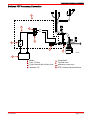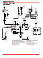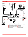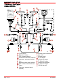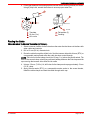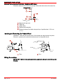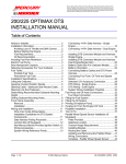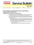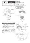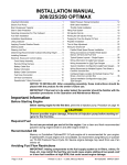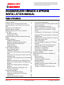
1
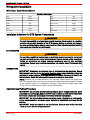
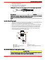
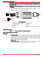
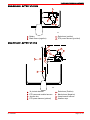
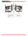
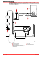
Mercury, Mercury Marine, MerCruiser, Mercury MerCruiser, Mercury Racing, Mercury Precision Parts,
Mercury Propellers, Mariner, Quicksilver, #1 On The Water, Alpha, Bravo, Pro Max, OptiMax, Sport-Jet,
K-Planes, MerCathode, RideGuide, SmartCraft, Zero Effort, M with Waves logo, Mercury with Waves
logo, and SmartCraft logo are all registered trademarks of Brunswick Corporation. Mercury Product
Protection logo is a registered service mark of Brunswick Corporation.
200/225/250/275 VERADO 4-STROKE
INSTALLATION MANUAL
Table of Contents
Notice to Installer ................................................... 2
Avoiding Loss of Throttle and Shift Control ........... 2
Accessory Electric Fuel Pump/Fuel Line Primer
Bulb ....................................................................... 2
Avoiding Fuel Flow Restriction .............................. 2
Boat Horsepower Capacity .................................... 2
Selecting Accessories For Your Outboard ............ 3
Fuel Tanks ............................................................. 3
Portable Fuel Tank ........................................... 3
Permanent Fuel Tank ....................................... 3
Determining Recommended Outboard Mounting
Height .................................................................... 4
Installing Outboard ................................................ 5
Installation Specifications..................................5
Maximum Outboard Mounting Height................5
Drilling Outboard Mounting Holes......................6
Lifting Outboard.................................................7
Fastening Outboard...........................................8
Power Steering Installation .................................. 10
Power Steering System...................................10
Installation Procedure......................................10
Connection of the Hydraulic Hoses to the Steering
Helm................................................................12
Connection of the Hydraulic Hoses to the Power
Steering Pump.................................................14
Connection of the Hydraulic Hoses to the Steering
Cylinder............................................................15
Electrical Connections to the Steering Pump. .17
Filling Power Steering System with Engine Not
Running...........................................................19
Filling Power Steering System with Engine
Running...........................................................21
Routing Connections Through the Cowl..........22
Fuel Hose Connection.....................................23
Wiring And Installation ......................................... 24
Wire Color Code Abbreviations.......................24
Installation Guidelines for DTS System
Components....................................................24
Data Harness Pulling Procedure.....................24
Page 1 / 51
Junction Box (If Equipped)...............................25
Non-Mercury Marine Provided Ignition Switch.25
Wiring Accessories..........................................26
System Wiring Reference Points.....................26
Battery Cable Size For Outboard Models........27
Connecting 14 Pin Data Harness - Single
Engine..............................................................29
Connecting 14 Pin Data Harness - Dual Engine
.........................................................................30
Installing DTS Command Module and Harness Single Engine...................................................31
Installing DTS Command Module and Harness Dual Engine/Single Helm.................................34
Battery Information..........................................35
Connecting Battery Cables and DTS Power
Harness...........................................................36
Connecting Fuel Tank And Speed Sensor .....39
Switched 12V Accessory Connection..............41
DTS Wiring - Single Engine.............................42
DTS Wiring - Dual Engine................................44
System Wiring Installation Checklist................45
Propeller Installation ........................................... 45
Paddle Wheel Speed Sensor Installation (If
Equipped) ............................................................ 47
Parts Provided ................................................ 47
Selecting Location .......................................... 47
Transom Angle Requirements ........................ 48
Installing Bracket ............................................ 48
Routing the Cable ........................................... 49
Installing and Removing the Paddle Wheel .... 50
Wiring Connections ......................................... 50
Template - Paddle Wheel Speed Sensor ....... 51
© 2004 Mercury Marine
90-10238051 JUNE 2004
200/225/250/275 VERADO 4-STROKE
Lubricant, Sealant, Adhesives
Tube Ref No.
Description
Where Used
Part No.
94
Anti-Corrosion Grease
Propeller shaft splines
92-802867A1
95
2-4-C Marine Lubricant with Teflon
Propeller shaft splines
92-802859A1
Notice to Installer
This Product Requires Electronic Calibration Before Use.
Installation of this product will require electronic calibration. This calibration must not be
attempted by anyone other than the Original Equipment Manufacturer (OEM) or a
Mercury technician trained in Digital Throttle and Shift systems (DTS) at an authorized
Mercury dealership. Improper installation and calibration of the DTS product will result in
a system which is inoperable or unsafe for use.
Avoiding Loss of Throttle and Shift Control
! WARNING
To avoid the possibility of serious injury or death from loss of boat control, do not splice
or probe into any wire insulation of the DTS system. Splicing or probing will damage
the wire insulation allowing water to enter the wiring. Water intrusion may lead to wiring
failure and loss of throttle and shift control.
Accessory Electric Fuel Pump/Fuel Line Primer Bulb
IMPORTANT: Do not install either an accessory electric fuel pump or a fuel line primer
bulb into the fuel system of this engine.
Avoiding Fuel Flow Restriction
IMPORTANT: Adding components to the fuel supply system (filters, valves, fittings, etc.)
may restrict the fuel flow. This may cause engine stalling at low speed, and/or a lean fuel
condition at high RPM that could cause engine damage.
Boat Horsepower Capacity
! WARNING
Using an outboard that exceeds the maximum horsepower limit of a boat can: 1) cause
loss of boat control 2) place too much weight at the transom altering the designed
flotation characteristics of the boat or 3) cause the boat to break apart particularly
around the transom area. Overpowering a boat can result in serious injury, death or
boat damage.
Page 2 / 51
90-10238051
200/225/250/275 VERADO 4-STROKE
Do not overpower or overload your boat. Most boats will carry a required capacity plate
indicating the maximum acceptable power and load as determined by the manufacturer
following certain federal guidelines. If in doubt, contact your dealer or the boat
manufacturer.
U.S. COAST GUARD CAPACITY
MAXIMUM HORSEPOWER XXX
MAXIMUM PERSON
CAPACITY (POUNDS)
XXX
MAXIMUM WEIGHT
CAPACITY
XXX
ob00306
Selecting Accessories For Your Outboard
Genuine Mercury Precision or Quicksilver Accessories have been specifically designed
and tested for this outboard
Some accessories not manufactured or sold by Mercury Marine are not designed to be
safely used with this outboard or outboard operating system. Acquire and read the
installation, operation, and maintenance manuals for all selected accessories.
Fuel Tanks
Portable Fuel Tank
Select a suitable location in the boat within the engine fuel line length limitations and
secure the tank in place.
Permanent Fuel Tank
Permanent fuel tanks should be installed in accordance with industry and federal safety
standards, which include recommendations applicable to grounding, anti-siphon
protection, ventilation, etc.
90-10238051
Page 3 / 51
200/225/250/275 VERADO 4-STROKE
Determining Recommended Outboard Mounting Height
66.0 cm
(26 in.)
b
63.5 cm
(25 in.)
e
60.9 cm
(24 in.)
58.4 cm
(23 in.)
e
c
b
56.0 cm
(22 in.)
53.3 cm
(21 in.)
a
d
50.8 cm
(20 in.)
48.2 cm
(19 in.)
10
20
30
40
50
60
70
80
f
ob01470
a - The solid line is recommended to determine the outboard mounting height.
b - The broken lines represent the extremes of known successful outboard
mounting height dimensions.
c - The line may be preferred to determine outboard mounting height dimension,
if maximum speed is the only objective.
d - The line may be preferred to determine outboard mounting height dimension
for dual outboard installation.
e - Outboard mounting height (height from a point on the pedestal 48 mm
[1-7/8 in.] above center of top mounting hole to the bottom of the boat
transom). For heights over 56.0 cm (22 in.), a propeller designed for surfacing
operation is usually preferred.
f - Maximum boat speed (m.p.h.) anticipated.
NOTICE
Page 4 / 51
•
The static waterline, with boat at rest, must be below the "MAX STATIC WATERLINE" mark on the
idle relief grommet (located at the rear of the outboard), when the outboard is fully tilted in/down. If
waterline is above "MAX STATIC WATERLINE" mark, adjust boat load forward or increase (raise)
outboard mounting height to correctly place mark above waterline.
•
Add 12.7 cm (5 in.) for XL models and 25.4 cm (10 in.) for XXL models to listed outboard mounting
height.
•
The mounting height of the outboard must not exceed 63.5 cm (25 in.) for XL models and 76.2 cm
(30 in.) for XXL models. Mounting the outboard higher may cause damage to the gearcase
components.
90-10238051
200/225/250/275 VERADO 4-STROKE
Increasing the mounting height will usually:
• Increase top speed
• Increase boat stability
• Cause propeller to break loose during planing or turning
Installing Outboard
Installation Specifications
a
a
b
4241
a - Minimum transom opening
b - Engine center line for dual engine - 66.0 cm (26 in.)
Minimum Transom Opening
Single engine
99.0 cm (39 in.)
Dual engine
165.0 cm (65 in.)
Maximum Outboard Mounting Height
The mounting height of the outboard must not exceed 63.5 cm (25 in.) for L models,
76.2 cm (30 in.) for XL models and 88.9 cm (35 in.) for XXL models. Mounting the outboard
higher may cause damage to the gearcase components.
ob01312
90-10238051
Page 5 / 51
200/225/250/275 VERADO 4-STROKE
MAXIMUM STATIC WATERLINE
The static waterline, with boat at rest, must be below the "MAX STATIC WATERLINE"
mark on the idle relief grommet (located at the rear of the outboard) when the outboard
is fully tilted in/down. If waterline is above "MAX STATIC WATERLINE" mark, adjust boat
load forward or increase (raise) outboard mounting height to correctly place mark above
waterline.
MAX STATIC
WATERLINE
4224
Drilling Outboard Mounting Holes
IMPORTANT: Before drilling any mounting holes, carefully read Determining
Recommended Outboard Mounting Height. There is a 19 mm (0.75 in.) difference
between the outboard mounting holes in the transom brackets.
! WARNING
Avoid possible serious injury or death. Do not, under any circumstances, allow the upper
outboard mounting bolts to be closer than 25.4 mm (1 in.) from the top of the boat
transom. Never install the upper mounting bolts through shims.
1. Mark four mounting holes on the transom using the transom drilling fixture.
b
a
a
c
or69-1
a - Drill guide holes
b - Transom drilling fixture - not included
c - Transom centerline
Transom Drilling fixture
Page 6 / 51
91-98234A2
90-10238051
200/225/250/275 VERADO 4-STROKE
2. Place masking tape directly onto the boat where the mounting holes will be drilled to
help keep the fiberglass from chipping.
3973
3. Using the drill guide holes on the transom drilling fixture, drill four 13 mm (17/32 in.)
holes perpendicular to and through the transom.
Lifting Outboard
1.
2.
3.
4.
90-10238051
Remove top cowl and engine flywheel cover.
Install lifting ring/flywheel puller to flywheel. Tighten bolts securely.
Lift engine using engine lift with a minimum capacity of 450kg (1000 lb.).
Avoid interference by placing the lower mounting bolts into the lower mounting slots
before placing outboard against the transom.
Page 7 / 51
200/225/250/275 VERADO 4-STROKE
5. Refer to Determining Recommended Outboard Mounting Height, and install outboard
to the nearest recommended mounting height.
a
b
3731
a - Lifting eye
Lifting Eye
b - Mounting bolts
91-895343T01
6. Fasten outboard with mounting hardware provided. Refer to Fastening Outboard.
Fastening Outboard
1. Place lower mounting bolts into mounting slots before placing outboard on transom.
2. Refer to Determining Recommended Outboard Mounting Height, and install outboard
to the nearest recommended mounting height.
3. Fasten outboard with the stainless steel bolts, nylon insert locknuts and flat washers
as shown.
Page 8 / 51
90-10238051
200/225/250/275 VERADO 4-STROKE
! CAUTION
To avoid loss of outboard, ensure that a minimum of two full threads of bolt extend
beyond locknut after tightening locknut. Ensure mounting nut is tightened against
transom, not the shank of the mounting bolt.
c
b
a
d
e
a - Transom bolts (1/2 x 20) (4)
b - Flat washers - outer (4)
c - Nylon insert locknuts (4)
5552
d - Flat washers - inner (4)
e - Marine sealer - apply to shank of
bolts, not threads
Outboard Transom Mounting Hardware - Supplied with Outboard
Part Number
Part Name
Description
10-67755003
Transom bolt
11-826711-17
Nylon insert locknut
12-28421
Washer - inner
0.516 in. ID x 1.50 in. OD
12-895062
Washer - outer
0.551 in. ID x 1.06 in. OD
1/2 x 20 x 5.50 in. long (3.25 in. thread)
1/2 x 20
Available Transom Mounting Bolts
90-10238051
Part Number
Part Name
Description
10-814259
Transom bolt
1/2 x 20 x 4.00 in. long (2.25 in. thread)
10-67755-1
Transom bolt
1/2 x 20 x 4.50 in. long (2.25 in. thread)
10-67755-2
Transom bolt
1/2 x 20 x 6.50 in. long (2.75 in. thread)
Page 9 / 51
200/225/250/275 VERADO 4-STROKE
Power Steering Installation
Power Steering System
a
b
c
ob01457
a - Steering helm
b - Steering cylinder on outboard
c - Power steering pump
Installation Procedure
NOTE: On some large/heavy dual outboard boats the steering forces generated in
extreme maneuvers may create loads that exceed the pump's pressure capacity. If the
happens, the operator may feel intermittent periods of load feedback at the steering
wheel. The steering wheel may feel hard to turn for brief periods during these extreme
maneuvers. If this happens and steering performance is deemed unacceptable for the
application, a second (accessory) cylinder may be rigged. When using a second steering
cylinder the 40cc helm should be replaced with a 50cc helm.
SELECTING LOCATION FOR THE POWER STEERING PUMP
! CAUTION
To ensure proper steering operation, hydraulic power steering system must be
protected from contamination. Make hydraulic connection in a clean work area. Route
hoses with the protective shipping caps in place. Remove protective shipping cap from
hose and component fitting as each connection is made.
1. Select a mounting location (floor or side of internal bulkhead) for the installation of the
power steering pump that meets the following requirements
Page 10 / 51
90-10238051
200/225/250/275 VERADO 4-STROKE
•
To reduce noise on aluminum or metal hulls, isolate steering hoses from hull with
suitable non-abrasive hangers.
•
Steering hoses from steering wheel helm must be free of twists or stress. Gently
secure hose bundle together with a cable tie, located approximately 25.4 cm
(10 in.) from the steering wheel helm.
•
Do not mount pump on an angle greater then 15° from vertical position.
•
The pump electrical wiring must be within reach of the auxiliary battery.
•
Pump should be mounted in an area that allows sound enclosure, cover removal,
and easy access to the fill cap.
•
Install pump in an area where bilge water will not contaminate the pump.
•
To reduce transmitted noise, mount pump on wood or fiberglass surface. Avoid
mounting pump on aluminum or steel surfaces.
REQUIRED MOUNTING CLEARANCES FOR THE POWER STEERING PUMP
a
c
d
b
ob01458
abcd-
215 mm (8 1/2 in.)
310 mm (12 7/32 in.) to top cover (not shown)
285 mm (11 1/4 in.)
432 mm (17 in.) clearance required for cover removal
INSTALLING POWER STEERING PUMP
1. The power steering pump can be mounted two ways:
•
On a side of the internal bulkhead
•
Mounted on the floor
90-10238051
Page 11 / 51
200/225/250/275 VERADO 4-STROKE
2. Mount the power steering pump at the selected location, using appropriate fastening
hardware suitable for the type of material and thickness of the mounting surface.
b
a
b
a
a
a
ob01459
Mounted on internal bulkhead
a - Lag screws or thru-bolts (3 or 4)
b - Mounting hardware
Mounted on floor
Connection of the Hydraulic Hoses to the Steering Helm
NOTE: Hoses must be routed up through steering helm opening in dash and secured to
helm fittings prior to mounting the steering helm.
1. Place the steering hoses through one backing plate on the internal side of the
dashboard. Route the steering hoses through the drilled opening, and place the
required amount of backing plates on the hoses on the external side of the dashboard.
NOTE: The number of backing plates varies depending on helm displacement.
a
4027
a - Backing plates
2. Remove and discard the shipping caps from ends of the four fittings on the steering
helm. Ensure the O-ring seals did not lift off with the shipping caps.
Page 12 / 51
90-10238051
200/225/250/275 VERADO 4-STROKE
3. Ensure O-ring seals are in place on end of steering helm fittings.
a
b
ob01460
a - O-ring seals (4)
b - Plug - not used
4. Make the hose connections to the steering helm as shown. Use a thin wrench and
hold the helm fittings from turning while tightening hoses. Do not over-tighten the hose
connections.
c
b
R STAR
L PORT
e
T
P
d
a
ob01461
abcde-
90-10238051
Thin wrench
Helm hex fitting wrench size (P & T) - 19 mm (3/4 in.)
Helm hex fitting wrench size (R & L) - 16 mm (5/8 in.)
Hydraulic hose hex fitting wrench size (P & T) - 21 mm (13/16 in.)
Hydraulic hose hex fitting wrench size (R STAR & L PORT) - 18 mm
(11/16 in.)
Helm Fitting ID Mark
Hose ID Mark
Description
P
P
Pressure from pump to helm
T
T
Tank low pressure return to pump
Page 13 / 51
200/225/250/275 VERADO 4-STROKE
Helm Fitting ID Mark
Hose ID Mark
Description
R
R-STAR
Hose connects to starboard side of steering cylinder
L
L-PORT
Hose connects to port side of steering cylinder
Connection of the Hydraulic Hoses to the Power Steering Pump
1. Remove and discard the yellow protector cap from end of tank low pressure fitting.
2. Connect the low pressure hydraulic hose from the steering helm to the low pressure
fitting on the pump reservoir as shown. Fasten hose to fitting with constant tension
spring clamp.
a
c
b
ob01462
a - Yellow protector cap (remove and discard)
b - Low pressure hydraulic hose from steering helm
c - Clamp
3. Ensure that O-ring seal is on end of hose.
Page 14 / 51
90-10238051
200/225/250/275 VERADO 4-STROKE
4. Connect the high pressure hydraulic hose from the steering helm to the pump as
shown.
a
b
ob01463
a - O-ring
b - High pressure hydraulic steering
hose
Connection of the Hydraulic Hoses to the Steering Cylinder
1. Route the hydraulic hoses to the outboard steering cylinder. Bulkhead fittings are
available if an opening does not exist in the engine well.
b
a
ob01464
a - Bulkhead fitting - bulkhead thickness up to 1.9 cm (0.75 in.) (22-892517)
b - Bulkhead fitting - bulkhead thickness up to 7.62 cm (3 in.) (22-892518)
NOTE: The 90° hose fittings on the steering cylinder can be rotated to align with hose
routing. Straight hose fittings (22-892519) are also available.
90-10238051
Page 15 / 51
200/225/250/275 VERADO 4-STROKE
2. Position the 90° hose fittings to the desired direction. Loosen fastening nuts in order
to rotate. Position fittings and re-tighten fastening nuts.
b
a
c
ob01465
a - Position fittings
b - 90° fitting
c - Straight fitting
3. Remove and discard the shipping caps from the two fittings on the steering cylinder.
Ensure O-ring seals did not lift off with shipping caps.
4. Ensure O-ring seals are in place on end of each fitting.
a
a
ob01466
a - O-rings
5. Make the hydraulic steering hose connections to the steering cylinder as shown.
b
RS
LP
TA
R
OR
T
a
ob01467
a - Port fitting (L PORT)
Page 16 / 51
b - Starboard fitting (R STAR)
90-10238051
200/225/250/275 VERADO 4-STROKE
Electrical Connections to the Steering Pump
NOTE: For single engine installation, the power steering pump battery cables should be
connected directly to the outboard starting battery.
b
e
f
+
a
c
g
d
i
k
b
h
j
4250
abcdef-
90-10238051
Single Engine Application
Engine
gBattery cable
hDTS power harness
iBattery
jPower steering fuse - 90 Amp
Power steering pump 12V positive k harness
Power steering pump
Driver module
Power steering pump ground
harness
Power steering signal harness
Engine signal harness
Page 17 / 51
200/225/250/275 VERADO 4-STROKE
NOTE: On multiple installations, the Automatic Battery Switch (ABS) (87-895091K01),
must be used to connect all outboard starting batteries to the power steering pump. The
ABS allows battery voltage to be drawn from the starting battery with the highest state of
charge.
+
a
k
e
c
-
f
g
m
+
b
d
k
h
i
-
m
l
j
4154
Dual Engine Application
abcdefg-
Page 18 / 51
Port engine
Starboard engine
Port battery
Starboard battery
Automatic Power Switch (APS)
Power Steering Pump
Power steering pump 12V positive
harness
h - Power steering pump ground
harness
i - Driver module
j - Dual engine power steering adaptor
k - DTS power harness
l - Power steering signal harness
m -Engine signal harness
90-10238051
200/225/250/275 VERADO 4-STROKE
1. Make electrical connections to the pump as shown.
c
e
BLK
-
b
+
RED
d
a
ob01468
a - Power steering pump
b - Auxiliary battery (preferred)
c - Diode harness
d - Battery leads
e - 3 pin connector from engine
Filling Power Steering System with Engine Not Running
Use SAE 0W-30 Full Synthetic Power Steering Fluid in the power steering system. In an
emergency, if recommended power steering fluid is not available, the use of any full
synthetic engine oil can be temporarily used. The power steering fluid should then be
drained and replaced with SAE 0W-30 Full Synthetic Power Steering Fluid as soon as
possible, to avoid loss of performance in power steering system.
Fluid Type
SAE 0W-30 Full Synthetic Power
Steering Fluid
Capacity
Mercury Part Number
1 - 2 liters (1 - 2 quarts) depending on length
of steering hoses
92-858002K01
1. Disconnect power steering signal harness from engine signal harness.
2. Connect the Power Steering Primer Module Kit to the power steering pump and 12
volt positive power source as shown.
d
c
BLK
-
b
+
RED
a
ob01469
a - Power steering pump
b - Primary battery
c - Battery leads
d - Power steering primer module
Power Steering Primer Module Kit
91-895040K01
3. Remove the filler cap and filter from the power steering pump.
90-10238051
Page 19 / 51
200/225/250/275 VERADO 4-STROKE
4. Fill the pump tank with recommended power steering fluid.
a
b
c
4101
a - Fill cap
b - Filter
c - Full level
IMPORTANT: The power steering module primer has two switches, "POWER" - "ON"
and "OFF", and "PUMP" - "ON" and "OFF". To power up and activate the power steering
pump, there are two steps: 1) Turn the "POWER" switch to the "ON" position to power
up pump, wait for two seconds, then, 2) Turn the "PUMP" switch to the "ON" position to
activate pump.
IMPORTANT: Do not run pump out of fluid. If pump draws air during bleeding, the
resulting re-bleeding will take two to three times longer than initial bleeding.
5. Power up and activate the pump until fluid drops halfway. Turn off both switches on
the power steering primer module and refill the pump tank. Repeat this operation until
pump tank stays full.
6. Power up and activate the pump while slowly turning the steering wheel towards the
full lock position in one direction. Carefully monitor the fluid level until fluid drops
halfway, stop turning the steering wheel and refill the pump tank. Repeat this
operation turning the steering wheel from full lock to full lock 10 times until pump tank
stays full.
7. For bleeding any air left in the steering system, power up and activate the pump. Turn
the steering wheel in one direction until the full lock position is met.
8. Attach an 8 mm I.D. (5/16 in. I.D.) transparent bleed hose to the bleed valve on the
end of the steering cylinder that the engine is pointing to. Route bleed hose into pump
tank (do not bleed power steering fluid into a different container, this will only be
pumping fluid out of the system that was just filled up).
Page 20 / 51
90-10238051
200/225/250/275 VERADO 4-STROKE
9. Open bleed valve to release any remaining air in the power steering system. Allow
adequate time, depending on length of power steering hose, for air to escape from
system. Tighten bleed valve securely and remove bleed hose.
a
b
3640
a - Bleed hose
b - Bleed valve in steering cylinder
10. Turn the steering wheel to opposite full lock position, and repeat steps 8 and 9.
11. Replace the filter and fill cap on the power steering pump.
12. If desired, the power steering system can be rechecked after sitting overnight to
remove any air that may possibly be left in the system. Repeat steps for bleeding
steering system, preceding.
13. Turn off both switches, remove the power steering primer module and reconnect the
power steering signal harness from the engine to the pump.
Filling Power Steering System with Engine Running
1. Remove the filler cap and filter from the power steering pump.
2. Fill the pump tank with recommended power steering fluid.
a
b
c
4101
a - Cap
b - Filter
c - Full level
3. Start and run the engine until the steering pump fluid drops halfway. Turn off the
engine and refill the pump. Repeat this operation until pump stays full.
4. Start and run the engine while slowly turning the steering wheel towards the full lock
position in one direction. Carefully monitor the fluid level until fluid drops halfway. Stop
turning wheel, turn off engine, and refill the pump tank. Repeat this operation turning
the steering wheel to full lock to full lock 10 times until pump tank stays full.
90-10238051
Page 21 / 51
200/225/250/275 VERADO 4-STROKE
5. For bleeding any air left in the steering system, start and run the engine, and turn the
steering wheel in one direction until the full lock position is met.
6. Attach an 8 mm (5/16 in.) I.D. transparent bleed hose to the bleed valve on the end
of the steering cylinder that the engine is pointing to. Route bleed hose into pump
tank (do not bleed power steering fluid into a different container, as this will only be
pumping fluid out of the system that was just filled).
7. Open bleed valve to release any remaining air in the power steering system. Allow
adequate time, depending on length of power steering hose, for air to escape from
system. Tighten bleed valve securely and remove bleed hose.
a
b
3640
a - Bleed hose
b - Bleed valve in steering cylinder
8. Turn the steering wheel to opposite full lock position, and repeat procedure for
bleeding steering system.
9. Replace the filter and filler cap on the power steering pump.
10. If desired, the power steering system can be rechecked after sitting overnight to
remove any air that may possibly be left in the system. Repeat steps for bleeding
steering system, preceding.
Routing Connections Through the Cowl
IMPORTANT: Ensure that sufficient excess exists in the wiring harness and battery
cables routed between the cowl fitting and the engine attachment point to relieve stress
and prevent hoses from being kinked or pinched. Ensure that excess exists in all hoses
and cables in full left and right turns and full tilt position.
NOTE: Mercury Marine suggests routing the wiring, cables and fuel hose through a
rigging hose or flexible sleeve from the engine to the boat's gunnel or motor well. Follow
the installation instructions included with the Rigging Hose or Flexible Sleeve Kit.
Page 22 / 51
90-10238051
200/225/250/275 VERADO 4-STROKE
1. Pull out the grommet fitting from the front cowl opening. Route the wiring harnesses,
battery cables, and fuel hose through the correct openings in the rubber grommet as
shown.
c
b
d
F
H
a
B
h
B
AWT
f
e
g
3723
abcdefgh-
Rubber grommet
Fuel hose
14 pin data harness
DTS power harness, vessel sensor harness, power steering pump harness
Large diameter battery cables
Small diameter battery cables
Grommet fitting
Front cowl opening
2. Insert rubber grommet into fitting and secure fitting in front cowl opening.
Fuel Hose Connection
FUEL HOSE SIZE
IMPORTANT: Fuel line inside diameter (I.D.) must be 10 mm (3/8 in.) with separate fuel
line/fuel tank pickup for each engine.
Fasten remote fuel hose to fitting with hose clamp.
F
E
a
b
3730
a - Remote fuel hose
90-10238051
b - Hose clamp
Page 23 / 51
200/225/250/275 VERADO 4-STROKE
Wiring And Installation
Wire Color Code Abbreviations
Wire Color Abbreviations
BLK
Black
BLU
Blue
BRN
Brown
GRY
Gray
GRN
Green
ORN or ORG
Orange
PNK
Pink
PPL or PUR
Purple
RED
Red
TAN
Tan
WHT
White
YEL
Yellow
LT or LIT
Light
DK or DRK
Dark
Installation Guidelines for DTS System Components
! WARNING
To avoid the possibility of serious injury or death from loss of boat control, do not splice
or probe into any wire insulation of the DTS system. Splicing or probing will damage
the wire insulation allowing water to enter the wiring. Water intrusion may lead to wiring
failure and loss of throttle and shift control.
DATA HARNESS
! WARNING
To avoid the possibility of serious injury or death from loss on boat control, do not pull
on cable connectors when pulling cable into boat. Observe correct pulling procedure.
Pulling on connectors can loosen terminals resulting in open or poor electrical
connections. Open or poor electrical connections may result in loss of throttle and shift
control.
CONNECTORS
IMPORTANT: Connectors should never have to be forced into the receptacle. Ensure
that connectors are free of any lubricant or dielectric grease before installation. When the
connector is properly aligned, it will only take a small amount of pressure to insert it into
the receptacle. Rotate the locking collar to secure the electrical connection.
NOTE: Connect only one data harness of the required length between the engine and
helm. If a data harness is too short, do not connect multiple harnesses together to make
up the required length. For installations requiring a data harness length longer than
12.2 m (40 ft.), contact Mercury Marine for more information.
Data Harness Pulling Procedure
IMPORTANT: Do not route data harness near engine ignition components (coils, spark
plug leads, and spark plugs), high power VHF coax or radios. An electrical field generated
from these components could cause interference with data transmission.
IMPORTANT: Do not route data harness near sharp edges, hot surfaces or moving parts.
Fasten cables away from any sharp edges, fasteners or objects that could wear into the
harness.
IMPORTANT: Avoid sharp bends in the data harness. Minimum bend radius should be
7.6 cm (3 in.) for the final wiring installation.
Page 24 / 51
90-10238051
200/225/250/275 VERADO 4-STROKE
1. Inspect the routing path to make sure surfaces are free of any sharp edges or burrs
that could cut the harness.
2. Install cable pulling tool to data harness.
3. Secure pulling tool with 2 cable ties.
IMPORTANT: The cables ties must be tight to prevent any slipping during installation.
3836
Data Cable Puller
91-888462A1
IMPORTANT: Carefully inspect data harness pins to ensure all pins are securely
fastened to data harness connector end following installation.
NOTE: Data harness should be secured with mounting clips or cable ties along the routing
path.
Junction Box (If Equipped)
•
•
•
•
•
•
Although the junction box connections are watertight, it is recommended that the
junction box be mounted in an area that stays relatively dry.
Mount in an area where the wiring connection will not get stepped on or disturbed.
Mount in an area that is accessible for troubleshooting and servicing the system.
Ensure the DTS command module harness will reach all the connection points.
Fasten all junction box connections within 25.4 cm (10 in.) of the junction box.
Seal all unused connections with weather caps.
c
b
a
d
e
ob01481
a - Clamp
b - Weather cap (859318T 2)
c - Junction box
d - 25.4 cm (10 in.)
e - DTS Command Module harness
Non-Mercury Marine Provided Ignition Switch
! CAUTION
Prevent unexpected engine start-up. Non-Mercury Marine ignition switches may allow
sufficient current leakage to cause engine to start unexpectedly.
90-10238051
Page 25 / 51
200/225/250/275 VERADO 4-STROKE
IMPORTANT: Correct ignition key switch must be used. If a non-Mercury Marine ignition
key switch is being used, make sure that the ignition switch being used meets the
requirement listed.
IMPORTANT: Current leakage exceeding 5 mA at 12 volts could cause engine to start
unexpectedly.
• Ignition key switch must pass ingress protection testing per IEC IP66 specification
minimum. Switches that do not pass this specification could leak current.
• Switches must contain an emergency stop circuit.
a
YEL/RED
RED
BLK/YEL
PPL
f
g
PPL / WHT
h
BLK
RED
YEL/RED
c
d
e
b
3641
BLK/YEL
BLK
PPL / WHT
PPL
abcd-
4 Position Key Switch
Connector - Packard Metripack
150 Series Sealed™ (6 pin)
Ignition switch
Crank
+ 12V
efgh-
Lanyard stop
Ground
Run
Accessory - 4 position key switch
Wiring Accessories
NOTE: Refer to Mercury Precision Parts Accessories Guide.
System Wiring Reference Points
FEATURES
•
•
•
Page 26 / 51
DTS power harness - Provides 12V power to the DTS system. Requires connection
to the starting battery. If starting battery is located at the helm, DTS power harness
accessory kit is required to minimize voltage drop. Use cable ties to secure power
harness leads to battery cables, beginning within 15 cm (6 in.) of battery posts and
continuing along the entire length of the harness.
Battery cables - Connect to the starting battery.
Vessel sensor harness - This harness connects to the main fuel tank sensor, auxiliary
fuel tank and the paddle wheel speed/temperature sensor, if equipped.
90-10238051
200/225/250/275 VERADO 4-STROKE
•
14 pin data harness - Connects between the command module harness and engine.
a
b
c
d
e
f
3675
abcdef-
14 pin data harness
Power steering pump harness
Vessel sensor harness
Battery cables
DTS power harness
5 Amp fuse
Battery Cable Size For Outboard Models
IMPORTANT: Only use copper battery cables. Do not use aluminum cables for any
outboard marine installations.
• If longer battery cables are required, the wire gauge size must increase. See chart
following for correct wire gauge size.
• DTS L models are equipped with 3.7 m (12 ft.) cables. DTS XL and XXL models are
not shipped with battery cables.
a
b
a - Wire gauge size
90-10238051
or70
b - Battery cable length
Page 27 / 51
200/225/250/275 VERADO 4-STROKE
Copper Battery Cable Wire Gauge Size
Wire Gauge Size Number SAE
Models
Cable Length
6-25 hp
30-115 hp (except OptiMax)
125-250 hp (except OptiMax)
OptiMax/Verado
2.4 m (8 ft.)
81.
61.
-
-
2.7 m (9 ft.)
6
4
-
-
3.0 m (10 ft.)
6
4
61.
-
3.4 m (11 ft.)
6
4
4
-
3.7 m (12 ft.)
6
4
4
41.
4.0 m (13 ft.)
6
2
4
2
4.3 m (14 ft.)
4
2
4
2
4.6 m (15 ft.)
4
2
4
2
4.9 m (16 ft.)
4
2
2
2
5.2 m (17 ft.)
4
2
2
2
5.5 m (18 ft.)
4
2
2
2
5.8 m (19 ft.)
4
2
2
2
6.1 m (20 ft)
4
2
2
2
6.4 m (21 ft.)
2
1
2
1
6.7 m (22 ft.)
2
1
2
1
7.0 m (23 ft.)
2
1
2
1
7.3 m (24 ft.)
2
1
2
1
7.6 m (25 ft.)
2
1
2
1
7.9 m (26 ft.)
2
1/0
1
1/0
8.2 m (27 ft.)
2
1/0
1
1/0
8.5 m (28 ft.)
2
1/0
1
1/0
8.8 m (29 ft.)
2
1/0
1
1/0
9.1 m (30 ft.)
2
1/0
1
1/0
9.4 m (31 ft.)
2
1/0
1
1/0
9.8 m (32 ft.)
2
1/0
1
1/0
10.1 m (33 ft.)
2
2/0
1/0
2/0
10.4 m (34 ft.)
2
2/0
1/0
2/0
10.7 m (35 ft.)
1
2/0
1/0
2/0
11.0 m (36 ft.)
1
2/0
1/0
2/0
11.3 m (37 ft.)
1
2/0
1/0
2/0
11.6 m (38 ft.)
1
2/0
1/0
2/0
11.9 m (39 ft.)
1
2/0
1/0
2/0
12.2 m (40 ft.)
1
2/0
1/0
2/0
1. Standard (original) cable length and wire gauge size.
Page 28 / 51
90-10238051
200/225/250/275 VERADO 4-STROKE
Connecting 14 Pin Data Harness - Single Engine
SINGLE HELM
IMPORTANT: Avoid sharp bends in the harness. Minimum bend radius should be 7.6 cm
(3 in.).
b
a
3619
a - 14 pin data harness
b - Clamp or cable tie
DUAL HELM
b
a
c
d
e
a - 14 pin data harness
b - Helm 2 (upper helm)
c - Helm 1 (lower helm)
90-10238051
3682
d - Dual helm adapter (Y harness)
e - Clamp or cable tie
Page 29 / 51
200/225/250/275 VERADO 4-STROKE
Connecting 14 Pin Data Harness - Dual Engine
SINGLE HELM
IMPORTANT: Avoid sharp bends in the harness. Minimum bend radius should be 7.6 cm
(3 in.).
a
b
3977
a - 14 pin data harness
b - Clamp or cable tie
DUAL HELM
a
c
b
c
d
e
a - Helm 2 (upper helm)
b - Helm 1 (lower helm)
c - 14 pin data harness
Page 30 / 51
3978
d - Dual helm adapter (Y harness)
e - Clamp or cable tie
90-10238051
200/225/250/275 VERADO 4-STROKE
Installing DTS Command Module and Harness - Single Engine
HARNESS INSTALLATION
• Locate a routing path for the harness connections so they reach their installation
points.
• Inspect the routing path to make sure surfaces are free of any sharp edges or burrs
that could cut the harness.
• Fasten and support the harness with clamps or cable ties along the routing path.
• Make sure all connections are tight and seal all unused connectors with weather caps.
a
b
3622
Single Helm Application
a - DTS command module harness
b - Clamp or cable tie
90-10238051
Page 31 / 51
200/225/250/275 VERADO 4-STROKE
NOTE: For dual helm application - Remove CAN 1 and CAN 2 terminator resistors from
helm 1 (helm closest to the engine), and seal connectors with weather caps.
a
c
Terminator
CAN 2
Terminator
CAN 1
f
e
d
h
g
c
b
d
3677
abcd-
Dual Helm Application
Helm 2 (upper helm)
Helm 1 (lower helm)
DTS command module harness
Clamp or cable tie
efgh-
CAN 1 connector
CAN 2 connector
Weather caps
Terminator resistors, blue (CAN1 &
CAN2)
MODULE INSTALLATION
• Although the Command Module connection is watertight, it is recommended that it be
mounted in an area that stays relatively dry.
• Mount in an area where the wiring connection will not get stepped on or disturbed.
• Mount in an area that is accessible for troubleshooting and servicing the system.
Page 32 / 51
90-10238051
200/225/250/275 VERADO 4-STROKE
•
Ensure the wiring harness connected to the command module will reach all the
connection points.
a
b
3625
Single Helm Application
a - DTS command module
b - Clamp or cable tie
a
c
d
e
b
f
3678
Dual Helm Application
a - Helm 2
b - Helm 1
c - DTS command module
90-10238051
d - Clamp or cable tie
e - Terminator resistors, blue (CAN1 &
CAN2)
f - Weather caps
Page 33 / 51
200/225/250/275 VERADO 4-STROKE
Installing DTS Command Module and Harness - Dual Engine/Single Helm
HARNESS INSTALLATION
• Locate a routing path for the harness connections so they reach their installation
points.
• Inspect the routing path to make sure surfaces are free of any sharp edges or burrs
that could cut the harness.
• Fasten and support the harness with clamps or cable ties along the routing path.
• Make sure all connections are tight and seal all unused connectors with weather caps.
Terminator
CAN 1
c
a
Terminator
CAN 2
b
Terminator
CAN 1
Terminator
CAN 2
c
e
d
a - CAN link harness
b - CAN 2 Terminator resistors - do
not remove
c - CAN 1 connectors
3689
d - Clamp or cable tie
e - DTS command module harness
MODULE INSTALLATION
• Although the Command Module connection is watertight, it is recommended that it be
mounted in an area that stays relatively dry.
• Mount in an area where the wiring connection will not get stepped on or disturbed.
• Mount in an area that is accessible for troubleshooting and servicing the system.
Page 34 / 51
90-10238051
200/225/250/275 VERADO 4-STROKE
•
Ensure the wiring harness connected to the command module will reach all the
connection points.
a
b
c
c
3691
a - DTS command module
b - Clamp or cable tie
c - CAN link harness
Battery Information
! CAUTION
Hex nuts must be used to secure battery leads to battery posts to avoid loss of electrical
power.
•
•
Do not use deep cycle batteries. Engines must use a marine starting battery with 1000
MCA, 800 CCA or 180 Ah.
When connecting engine battery, hex nuts must be used to secure battery leads to
battery posts. Torque nuts to specification.
Description
Nm
lb. in.
Hex nuts
13.5
120
lb. ft.
IMPORTANT: Battery cable size and length is critical. Refer to engine installation manual
for size requirements.
90-10238051
Page 35 / 51
200/225/250/275 VERADO 4-STROKE
Decal needs to be placed on or near battery box for future service reference. One
5/16 in. and one 3/8 in. hex nut are supplied per battery for wing nut replacement. Metric
hex nuts are not supplied.
NOTICE - DTS & Optimax Engines
DO NOT USE DEEP CYCLE BATTERIES!
DTS (Digital Throttle and Shift) applications and
Optimax engines must use a marine starting
battery with 1000 MCA, 800 CCA, or 180 Ah.
rating.
13.5Nm (120 lbs. in.)
DO NOT
USE WING
NUTS.
IMPORTANT:
Battery cable size and length is critical. Refer to
engine installation manual for size requirements.
37-895387
Place decal on or near battery box for future service
reference. 5/16" and 3/8" hex nuts supplied for
wing nut replacement. Metric hex nuts not supplied.
3486
Connecting Battery Cables and DTS Power Harness
! CAUTION
To avoid the possibility of loss of electrical power due to the DTS power harness
connection being pulled off battery, fasten the DTS power harness to one of the battery
cables near the battery with cable tie.
•
•
•
Install DTS power harness directly to the starting battery only.
Do not extend lead length of harness.
See accessory manual for optional lead connection kit.
3711
Page 36 / 51
90-10238051
200/225/250/275 VERADO 4-STROKE
SINGLE ENGINE - BATTERY AT STERN
a
c
b
d
3679
a - Battery
b - Black sleeve (negative)
c - Red sleeve (positive)
d - DTS power harness (provided)
SINGLE ENGINE - BATTERY AT HELM
b
d
c
e
f
a
h
g
3699
abcd-
90-10238051
14 pin data harness
DTS command module harness
Junction box
DTS power harness (optional)
efgh-
Red sleeve (Positive)
Black sleeve (Negative)
Vessel sensor harness
Weather caps
Page 37 / 51
200/225/250/275 VERADO 4-STROKE
DUAL ENGINE - BATTERY AT STERN
g
e
c
c
f
a
b
d
a
b
d
3680
abcd-
Page 38 / 51
Red sleeve (positive)
Black sleeve (negative)
Battery
DTS power harness (provided)
e - Ground cable
f - Data cable
g - Vessel sensor harness
90-10238051
200/225/250/275 VERADO 4-STROKE
DUAL ENGINE - BATTERY AT HELM
d
b
a
c
c
b
a
e
g
f
f
h
3701
abcd-
Black sleeve (negative)
Red sleeve (positive)
DTS power harness (optional)
DTS command module harness
efgh-
Junction box weather caps
14 pin data harness
Ground cable
Vessel sensor harness
Connecting Fuel Tank And Speed Sensor
IMPORTANT: Do not connect the blk/orn wire (if equipped) to the fuel tank sensor when
there is an engine battery ground strap connected to the fuel tank or sender assembly.
If not used, plug the unused open bullet connector with rubber plug.
IMPORTANT: If fuel tank is plastic and fuel sensor mounting plate is not connected to
battery ground, connect blk/orn wire (if equipped) to fuel sender mounting plate.
90-10238051
Page 39 / 51
200/225/250/275 VERADO 4-STROKE
IMPORTANT: Metal fuel tanks must be grounded to hull or battery ground in accordance
to coast guard regulations.
d
e
LT.BLU/BLK
BLK/ORG
BLK/ORG
TAN/ORG
PUR/YEL
GRY/BLU
BLK/ORG
PNK/BLK
WHT
YEL
BLU
BLK
c
b
a
5759
a - Paddle wheel kit
b - Vessel harness
c - Black/orange wire connection, if
equipped
Page 40 / 51
d - Fuel tank
e - To second fuel tank
90-10238051
200/225/250/275 VERADO 4-STROKE
Switched 12V Accessory Connection
e
c
d
PUR
RED
f
b
g
h
+
ob01495
-
a
abcd-
90-10238051
Battery
Fuse - 40 Amp
Power harness with 40 Amp fuse
Switched 12V
efgh-
Complete kit
Terminal block
Accessory power relay
DTS Command Module harness
Page 41 / 51
200/225/250/275 VERADO 4-STROKE
DTS Wiring - Single Engine
PANEL CONTROL
a
b
OFF O
N
BLK
BLK/YEL
BLK
BLK/YEL
c
WHITE
BLUE
e
+
BLK/ORG
PUR/YEL
GRN/YEL
GRN/ORG
GRN/RED
-
d
f
g
j
i
h
3718
abcde-
Page 42 / 51
Start/stop switch (optional)
SmartCraft System View (optional)
SmartCraft Link Gauge (optional)
GPS connection
Displace harness
fghij-
Cable adaptor (male to female)
Weather caps
Junction box (optional)
Accessory power relay (optional)
Foot throttle (optional)
90-10238051
200/225/250/275 VERADO 4-STROKE
CONSOLE CONTROL
a
b
OFF O
BLK
c
BLK/YEL
BLK
BLK/YEL
N
WHITE
BLUE
e
-
+
BLK/ORG
PUR/YEL
GRN/YEL
GRN/ORG
GRN/RED
d
f
g
j
i
h
3717
abcde-
90-10238051
Start/stop switch (optional)
SmartCraft System View (optional)
SmartCraft Link Gauge (optional)
GPS connection
Display harness
fghij-
Cable adaptor (male to female)
Weather caps
Junction box
Accessory power relay (optional)
Foot throttle (optional)
Page 43 / 51
200/225/250/275 VERADO 4-STROKE
DTS Wiring - Dual Engine
CONSOLE CONTROL
n
q
p
m
o
l
l
k
j
j
i
i
h
+
d
d
g
g
e
e
c
f
f
i
a
c
s
b
b
r
3309
abcdefghij-
Page 44 / 51
To port engine
Terminator resistor
DTS Command Module
Junction box connection (optional)
Connector - Zero Effort controls
Horn
Accessory power relay (optional)
DTS Command Module harness
Clamp
Connector - stop/start switch
(optional)
k - Remote control connections
l - Key switch
m -Remote control
n - To port engine
o - Lanyard stop switch
p - To starboard engine
q - System View (optional)
r - To starboard engine
s - CAN link harness
90-10238051
200/225/250/275 VERADO 4-STROKE
System Wiring Installation Checklist
DATA CABLE
Verify the data harness is not routed near sharp edges, hot surfaces or moving parts.
Verify data harness is not routed near ignition components (coils, spark plug leads,
and spark plugs), high power VHF coax or radios.
JUNCTION BOX (IF EQUIPPED)
Verify the data harness is not routed near sharp edges, hot surfaces or moving parts.
Ensure the harness connections are fastened within 25.4 cm (10 in.).
Verify that all unused receptacles are covered with a weather cap.
NON-MERCURY MARINE SUPPLIED IGNITION KEY SWITCH
If a non-Mercury Marine ignition key is used, verify that it passes the ingress protection
testing per IEC IP66 specification minimum. Ignition switches must pass this
specification.
ELECTRONIC REMOTE CONTROL
Ensure Electronic Remote Control (ERC) connections are completed following ERC
installation instructions prior to engine operation.
DTS COMMAND MODULE HARNESS
Verify that all connectors are properly inserted and locked in their receptacle (remote
control, key switch, command module, lanyard stop switch and junction box, if
equipped).
Verify that while moving the remote control handle (full forward and full reverse) the
harness has unobstructed movement (moves freely).
Verify that the lanyard stop switch is wired into the system correctly.
Verify that the harness is fastened along the routing path.
Verify that all unused connectors have weather caps to prevent corrosion.
BATTERY
Verify that wing nuts have been replaced with hex nuts, provided.
Verify that all engine battery cables are connected to the correct terminals.
Verify that the DTS power harness leads are connected to the starting battery and
secured with locknuts.
Ensure the 5 Amp fuse for the DTS power harness is accessible.
LANYARD STOP SWITCH
Verify that the switch is installed.
Verify that the switch is connected to the DTS command module harness.
Propeller Installation
! WARNING
When installing or removing propeller, ensure the remote control is in neutral position
and the key switch is "OFF". Place a block of wood between the anti-cavitation plate
and propeller to prevent accidental starting and to protect hands from propeller blades
while removing or installing nut.
1. To aid in future removal of the propeller, liberally coat the propeller shaft splines with
one of the following Mercury/Quicksilver products:
90-10238051
Page 45 / 51
200/225/250/275 VERADO 4-STROKE
Tube Ref No.
Description
Where Used
Part No.
94
Anti-Corrosion Grease
Propeller shaft splines
92-802867A1
95
2-4-C Marine Lubricant with
Teflon
Propeller shaft splines
92-802859A1
2. Flo-Torq II Drive Propellers - Install forward thrust hub, replaceable drive sleeve,
propeller, thrust hub, propeller nut retainer, and propeller nut onto the shaft.
a
b
e
c
d
a - Propeller nut
b - Propeller nut retainer
c - Thrust hub
f
ob00421
d - Propeller
e - Replaceable drive sleeve
f - Forward thrust hub
3. Place a block of wood between gearcase and propeller and torque nut to specification.
Description
Nm
Nut
75
lb. in.
lb. ft.
55
4. Secure propeller nut by bending three of the tabs into the thrust hub grooves.
ob00422
Page 46 / 51
90-10238051
200/225/250/275 VERADO 4-STROKE
Paddle Wheel Speed Sensor Installation (If Equipped)
Parts Provided
d
a
i
e
i
c
b
ABCD
h
f
abcde-
g
Spare pin yoke
Wire retainer
Connector
Bracket
Paddle wheel
j
fghij-
ob01505
Flat washer (2)
#10 - 19 mm (3/4 in.) screw (4)
Cable cap
#6 - 12 mm (1/2 in.) screw (4)
Clamp (2)
Selecting Location
Single engine installation - Mount paddle wheel on the transom where the propeller blade
is rotating downward. Usually the right (starboard) side to minimize cavitation. If feasible,
mount at least 50 mm (2 in.) beyond the swing radius of the propeller.
Dual engine installation - Mount the paddle wheel between the engines as close to the
center line (keel) of the boat as possible. On slower, heavier displacement boats,
however, positioning it farther from the keel is acceptable.
NOTE: Do not mount the paddle wheel directly behind any stakes, ribs, intakes or outlets
for live wells or any protrusion that may cause turbulence or cavitation.
a
ob01506
a - 50 mm (2 in.)
90-10238051
Page 47 / 51
200/225/250/275 VERADO 4-STROKE
Transom Angle Requirements
Standard 13° to 20° transoms - No special adjustment required.
a
b
ob01507
a - 13° transom angle
b - 20° transom angle
Stepped or undercut transom with 3 angles - A small shim of tapered plastic, metal or
wood must be fabricated and installed as shown. Mount the paddle wheel on the step for
best performance.
a
ob01508
a - Shim
Installing Bracket
1. Cut out the template. At the location selected, tape the template to the transom. Make
sure the black dotted line on the template is aligned with the transom bottom edge,
as shown.
NOTE: The mounting template provided is located on the last page of this instruction
sheet.
2. Using a #28 or 9/64 in. bit, drill two 22 mm (7/8 in.) deep holes where indicated on
the template. To prevent drilling too deeply, wrap masking tape around the drill bit
22 mm (7/8 in.) from the point end of drill bit.
NOTE: In fiberglass hulls, first chamfer the gelcoat using a 6 mm (1/4 in.) drill; drilling
about 15 mm (1/16 in.) deep to prevent surface cracks.
3. To prevent water seepage into the transom, apply a marine sealer (such as RTV) to
the two #10 screws provided. Using the washer provided, attach and tighten the
bracket to the hull making sure the bracket is flush with the underside of the hull.
Page 48 / 51
90-10238051
200/225/250/275 VERADO 4-STROKE
4. Fill any gap between the housing and the transom with a caulking material, as shown.
Using a putty knife, smooth the surface to ensure proper water flow.
a
e
b
c
a - Template
b - 50 mm (2 in.)
c - #10 screw
d
ob01509
d - Flat washer (2)
e - Caulking
Routing the Cable
DRILLING HOLE THROUGH TRANSOM (OPTIONAL)
1. Select a transom location for the hole above the water line that does not interfere with
other cables and controls.
2. Drill a 15 mm (5/8 in.) diameter hole.
3. Route the cable through the drilled hole. Seal the transom hole with silicone (RTV) or
a comparable marine sealer after the cable has been routed through.
NOTE: The hole for the first clamp should be 25 mm (1 in.) above the paddle wheel. The
hole for the second clamp should be positioned halfway between the first clamp and the
cap covering the transom hole drilled for the cable.
4. Using a 2.8 mm (7/64 in.) bit, drill holes for the clamps and cap approximately 13 mm
(1/2 in.) deep.
5. Apply silicone sealer (RTV) or a comparable marine sealer to the screw threads,
install the cable clamps and feed the cable through cable cap.
90-10238051
Page 49 / 51
200/225/250/275 VERADO 4-STROKE
WITHOUT DRILLING HOLE THROUGH TRANSOM (OPTIONAL)
Route the cable over the transom or through a drain hole that is above the water line.
a
b
e
c
d
abcde-
ob01510
Splash well drain hole
Cable cap
Cable clamp
Paddle wheel assembly
Distance between first cable clamp and top of paddle wheel - 25.4 mm
(1.0 in.)
Installing and Removing the Paddle Wheel
Installation - Slide the pins into the slots in the bracket and snap the tabs into place.
Removal - squeeze open (unlock) the tabs and pull on the paddle wheel.
a
b
ob01511
a - Tabs
b - Pins
Wiring Connections
IMPORTANT: Before making wire connections, make sure wires are routed through the
transom.
Page 50 / 51
90-10238051
200/225/250/275 VERADO 4-STROKE
NOTE: Wires can only be pushed into the connector one way. Align the wire terminal with
the tabs inside the connector. Have the wiring routed through the transom. Push each
wire terminal into its respective location in the connector. Push wire in until they snap into
place. Secure wires into connector with the wire retainer.
DC BA
DC B A
WHT
YEL
BLU
BLK
b
a
b
a - Connector
ob01512
b - Wire retainer
Template - Paddle Wheel Speed Sensor
a
b
ob01513
a - Drill holes here
b - Align dotted line with the transom bottom edge and fold under
90-10238051
Page 51 / 51