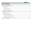
1
INSTALLATION MANUAL
English Edition
D75X ULTRA SHORT SERIES
SAFETY INSTRUCTION
For your safety, please read the instruction before using the wall mount bracket. Any improper disposition
caused by ignoring this manual may damage the hanger frame and result in personal injury and property damage.
Please keep the manual properly for future reference.
Please read the installation manual and safety instruction of the projector that matches our wall mount bracket
and operate according to the instruction.
SYMBOL INSTRUCTION
In order to avoid personal injury and property damage, the following warning symbols are used in
this setting manual. Please make sure that you have understood all these warning symbols while
reading this instruction.
!
WARNING
!
CAUTION
Ignoring this signal may lead to improper handling and result in
personal injury, even death.
Ignoring this signal may lead to improper handling and result in
personal injury or machine damage.
Useful messages.
Compulsory operations that must be conducted.
Recommended operations that should be conducted.
SAFETY PROTECTION MEASURES FOR SETTING
!
WARNING
The wall mounted bracket is designed for installation of projector on walls. The weight of the installation object
other than the designed projector may damage the wall mounted bracket, and if the wall mounted bracket falls,
personal injury and property damage may happen.
Installation (wall installation) should be performed by specialists who have technical knowledge and ability.
Incomplete or improper installation may cause wall mounted bracket to fall, resulting in personal injury or
property damage.
Please install the wall mounted bracket according to this instruction.
Otherwise, the wall mounted bracket may fall and result in personal injury or an accident.
Operating power cord with care.
Improper operation could cause fire or electric shock. Please comply with the following requirements
while operating:
1:Do not operate the power plug when your hands are wet.
2:Do not use damaged and changed power cord.
3:Do not employ excessive force while pulling power cord when it passes through the wall mount bracket.
If the position of installation of the wall mounted bracket is prone to be affected by vibration and impact, please
do not install the wall mounted bracket.
Vibration and impact may damage the projector and the installation plate, or even may result in the wall
mounted bracket and projector falling, resulting injury of people and damage of property.
Talling the wall mount bracket, please adopt methods that can support the projector and wall mount bracket as well as
to eliminate any vibration from the horizontal level.
M8 nut and screw should be applied. Nut and screw that are less than 8M may lead to hanger falling. DELTA is
disclaim from the responsible for any loss and damage caused by insufficient holding strength of the wall or improper
installation.
The installation should be conducted by two qualified person concurrently. If it is necessary to unscrew any nuts,
please take care that the wall mounted bracket does not fall. If the hanger or the projector falls, personal injury or
property loss may occur.
1
!
WARNING
If the wall mounted bracket is meant for installation of the projector on walls and the wall should be strong
enough to hold the projector and wall mounted bracket.
The wall mounted bracket should be installed on concrete walls. The quality of projector and hanger should
be qualified before installation, and the strength of walls should be verified and maintained. If the strength of
walls is not strong enough, please strengthen them before installation.
Please test the wall mounted bracket at regular intervals so as to make sure that there are no broken parts or
loose screws.If any broken part is found, please refrain from using the wall mounted bracket. If the wall mounted
bracket or projector falls, personal injury or property loss may occur.
Please do not with or modify the wall mounted bracket.
Please do not hang up the wall mounted bracket or hang things on the wall mounted bracket. If the projector or
the wall mounted bracket falls, personal injury or property loss may occur.
Glues lubricant or oil should not be used to wall mounted bracket can chemical attack which could result in a
rupture of the wall mounted bracket and then cause the projector to fall. As a result, personal injury or property
loss may occur.
Please tighten all the nuts and screws after adjustment. Otherwise, the projector or hanger may fall and lead to
personal injury or property lass.
Please refrain from loosening the nuts and screw after installation, unless otherwise deemed necessary and
performed by qualified specialists who have technical knowledge and ability.
Please test the wall mounted bracket at a regular interval to ensure the nuts and screw are tight. If the nuts and
screws are found loose, please tighten them, otherwise, the projector or the wall mounted bracket may fall and cause
personal injury and property loss.
!
CAUTION
Please do not install the hanger frame in places where the temperature could be higher than that the projector’s
maximum sustainable temperature, because the exceeding high temperature may damage the projector.
Please avoid installing the wall mounted bracket in places that is too wet or too dusty so that lens and optical
components can be protected from being contaminated.
While adjusting wall mounted bracket, please do not employ excessive force because the wall mounted bracket
may break and cause personal injury.
Only professional person can dismantle or reset the projector (including maintaining and overhauling). Please
consult the relevant information as illustrated in the instructions.
THE LOCATION FOR WALL MOUNTED BRACKET
1:Conducting power routing in advance in the position where the hanger frame is installed.
2:The position should be away from other electrical equipments, such as fluorescent lamps and air condition.Some
fluorescent lamps may cause interference signal to the projector’s remote control.
3:The length of connecting power cord should be less than 20 meters so as to reduce noise interference.
4:Plug-in screen or flat screen is suggested.
5:When using interactive function, please make sure to set the projector under the following condition,
(1):Projection screen is rectangle in shape with no distortion.
(2):The vertical and horizontal angle between projector and the projection screen should be less than 3 degree
comparing to the projector screen.
(3):The horizontal and vertical keystone correction should be less than 5 degree while using keystone correction,
ABOUT THIS INSTALLATION INSTRUCTION
This instruction introduces how to use customized wall mounted bracket to install D75 ultra
short throw projector on walls. The unit of measurement for all sizes mark place in this instruction
is in “mm”.
2
1 PACKAGING ITEMS
P. 4
2 SPECIFICATIONS
P. 5
3 PROJECTION DISTANCE CHART
P. 7
4 INSTALLATION STEPS FOR WALL MOUNTED BRACKET
P. 9
(1):Dismantle parts
(2):Verify the strength of walls, installation environment, installation
position and drill holes on the walls.
(3):Install hanger frame on walls.
(4):Verify the distance of the projector. Move the three axis
fine-tuner to proper position according to the projector distance
chart.
(5):Power cord should pass through the hanger frame.
(6):Adjust the slider plate up and down to align to the standard position.
(7):Install the projector onto the hanger frame.
(8):Connect the power cord and other electrical cables to the
projector.
5 ADJUSTING STEPS OF PROJECTOR IMAGE
P. 13
(1) Switch on the projector
(2) Adjust the aspect ratio
(3) Display the test image
(4) Adjust the left and right alignment position
(5) Adjust the up and down rotation
(6) Adjust the left and right rotation
(7) Adjust the keystone
(8) Adjust the image size
(9) Adjust the image up and down
(10) Switch off the testing image display
3
HARDWARES INCLUDED
FRAME 3
FRAME 4
FRAME 7
FRAME 5
FRAME 6
FRAME 2
TRI-AXIS FINE-TUNING COMPONENTS
FRAME 1
D75X ULTRA SHORT SERIES (BRACKET 1)
SETTING DRILLING PAPER (1:1)
D751ST XGA 0.43
Screen size
S/N
114
A
A
inch
mm(diagonal)
mm
1727
11.86
328.5
2
75
1905
12.88
354.4
3
77
1956
13.18
361.4
4
78
1987
13.18
362
5
80
2032
13.60
372.6
6
82
2083
13.90
380.2
7
85
2159
14.32
390.9
D755WT WXGA 0.35
Screen size
85
S/N
A
A
4 X A- 8.5 THREAD
WITH DEPTH 60MM
H1 VERTICAL DISTANCE
(THE DISTANCE FROM
PROJECTED SCREEN
TO THIS PART)
Screen shot
inch
68
TOP
PART LIST
H1 Vertical distance
1
IT MUST ALIGN CENTER OF SCREEN
CENTRAL LINE WHEN INSTALLING
inch
mm(diagonal)
H1 Vertical distance
inch
mm
1
80
2032
11.02
307.2
2
85
2159
11.59
321.5
3
87
2210
11.82
327.4
4
90
2286
12.16
336.1
5
92
2337
12.38
341.6
6
95
2413
12.72
350.2
2464
2540
12.95
356.1
13.26
364.1
7
8
97
100
Description:
1.“A” is the drill location. Please
review the description in manual
page 9.
2.This screenshot is only for D751ST
XGA 0.43/D WXGA 0.35 hanger.
3.The scale in the screenshot for all
indicated location is 1:1.
D75X INSTALLATION (FRAME 1) SETTING
DRILLING PAPER (1:1)
Hardware Specifications
Qty
Purpose
M4*10mm ball head cross head screw (with flat
gasket and spring washer)
3 (pcs)
Used for connecting wall mounted bracket
structure # 7 with projector
M8*70mm setscrew (with nut, flat gasket and
spring washer)
4 (pcs)
Used for installing and fixing wall mounted
bracket structure #1 onto the wall
1:Please follow the instructions in the manual and install with the attached hardwares.
2:Please prepare the required tools and hardwares before installation
4
SPECIFICATION
Spec
Description
Gross mass of hanger
frame
About 4.72kg
The three axis fine-tuning components(2.82kg), wall fixture
hardwares(0.86kg), independent components packed seperately (0.12kg).
Maximum load capacity
30kg
Item
The left and right
adjusting range
±40mm
Remark
Not inclusive of wall mounted bracket’s weight.
Frame structure # 3 adjustable by 30mm, frame structure # 7 adjustable by
±10mm.
P. 13
The up and down
rotation adjusting range
±5°
The three axis fine-tuner does horizontal scrolling adjustment
P. 14
The left and right
rotation adjusting range
±5°
The three axis fine-tuner does horizontal rotating adjustment
P. 15
Keystone adjusting
range
±5°
The three axis fine-tuner does vertical scrolling adjustment
P. 16
Forward and backward
adjustment by range
Up and down
adjustment by range
Can be adjusted
120mm forward
P. 17
±40mm
P. 18
D75X ULTRA SHORT SERIES (BRACKET 1)
SETTING DRILLING PAPER (1:1)
D751ST XGA 0.43
Screen size
114
A
A
TOP
H1 Vertical distance
mm
S/N
inch
1
68
1727
inch
11.86
328.5
2
75
1905
12.88
354.4
3
77
1956
13.18
361.4
4
78
1987
13.18
362
5
80
2032
13.60
372.6
380.2
390.9
mm(diagonal)
6
82
2083
13.90
7
85
2159
14.32
S/N
inch
1
80
2032
11.02
307.2
2
85
2159
11.59
321.5
3
87
2210
11.82
327.4
4
90
2286
12.16
336.1
5
92
2337
12.38
341.6
6
95
2413
12.72
350.2
7
97
100
2464
2540
12.95
356.1
13.26
364.1
D755WT WXGA 0.35
85
Screen size
A
A
4 X A-Ø8.5 THREAD
WITH DEPTH 60MM
H1 VERTICAL DISTANCE
(THE DISTANCE FROM
PROJECTED SCREEN
TO THIS PART)
IT MUST ALIGN CENTER OF SCREEN
CENTRAL LINE WHEN INSTALLING
8
mm(diagonal)
H1 Vertical distance
inch
mm
Description:
1.“A” is the drill location. Please review the
description in manual page 9.
2.This screenshot is only for D751ST
XGA 0.43/D WXGA 0.35 hanger.
3.The scale in the screenshot for all
indicated location is 1:1.
D75X INSTALLATION (FRAME 1) SETTING DRILLING PAPER (1:1)
5
D
H1
27.2
SCREENSHOT OF PROJECT DISTANCE
SCREEN
6
PROJECT DISTANCE
D751ST XGA 0.43
Screen size( diagonal)
Screen width
Screen height
Projecting distance (D)
Vertical distance( H1)
inch
mm
inch
mm
inch
mm
inch
mm
inch
mm
68
1727
54
1382
40
1036
11.16
283.4
11.86
328.5
75
1905
59
1524
45
1143
13.83
351.4
12.88
354.4
77
1956
61
1565
46
1173
14.62
371.4
13.18
361.4
78
1987
61
1566
46
1175
14.62
371.4
13.18
362
80
2032
63
1626
48
1219
15.72
399.4
13.60
372.6
82
2083
65
1666
49
1250
16.51
419.4
13.90
380.2
85
2159
67
1727
51
1295
17.61
447.4
14.32
390.9
D755WT WXGA 0.35
Screen size( diagonal)
Screen width
Screen height
Projecting distance (D)
Vertical distance( H1)
inch
mm
inch
mm
inch
mm
inch
mm
inch
mm
80
2032
67
1723
42
1077
11.11
282.3
11.02
307.2
85
2159
71
1831
45
1144
12.73
323.3
11.59
321.5
87
2210
73
1874
46
1171
13.40
340.3
11.82
327.4
90
2286
76
1939
47
1212
14.38
365.3
12.16
336.1
92
2337
77
1982
48
1239
15.01
381.3
12.38
341.6
95
2413
80
2046
50
1279
15.98
405.8
12.72
350.2
97
2464
81
2089
51
1306
16.65
422.8
12.95
356.1
100
2540
85
2154
53
1346
17.55
445.8
13.26
364.1
7
ASSEMBLY BREAKDOWN DIAGRAM
Quick Installation Steps:
Step 1: frame #1 setting drilling paper of ultra short series (1:1) to the proper position in up screen (see
details please refer to P.9). Perforate the setting wall. (percussion drill and drill 8.5, 60mm
depth)
Step 2: Install M8*70 setscrew in the wall’s hole.
Step 3: Use M8*70 setscrew (4X) fix structure frame # 1 to the wall’s hole.
Step 4: Install structure frame # 2 on structure frame # 1 (see P.10), switch it to intermediate position
and use screw B (M4*10 up and down adjusting fixing screw) to lock it yet.
Step 5: Loosen screw “C”, decline structure frame # 3 by 5 degree to aim at the positioning peg, and
position the slider structure into structure frame # 2’s slide-way. Adjust the slide-way to
intermediate position and tighten the screw “C” into structure frame # 2 ‘s threaded hole, but do
not lock it. When the positioning is in place, tighten the screw “C”. (see details please refer to
P.11)
Step 6: Use “I” screw to connect structure frame # 7 and projector. Fix them, and install them on
structure frame # 6. After adjusting structure frame # 7 to a proper position, lock screw “H”. (see
P.12)
H:3-M4*10 BRACKET
7 TIGHTEN SCREW
D:4-M4*10 PARALLEL
ADJUSTMENT FIXING
SCREW
G:TRAPEZOID ADJUSTMENT NUT
ROTATION ASIX
F:PARALLEL ADJUSTMENT
FIXING SCREW
E:VERTICAL ROTATION
ADJUSTMENT FIXING
NUT
C:2-M4*10 PARALLEL
ADJUSTMENT FIXING SCREW
STEP5
FRAME 3
STEP5
FRAME 2
STEP4
M:VERTICAL ROTATION
ADJUSTMENT FIXING
SCREW
A:4-M8*70
SETSCREW
STEP2
FRAME 5
FRAME 6
STEP6
FRAME 7
SETTING DRILLING PAPER
OF ULTRA SHORT SERIES
(1:1) TO THE PROPER
POSITION IN UP SCREEN
I:3-M4*10 PROJECTOR
CONNECTION SCREW
STEP6
FRAME 4
FRAME 1
STEP3
B:4-M4*10 VERTICAL ROTATION
ADJUSTMENT FIXING SCREW
STEP4
8
INSTALLING STEP 1
Installing steps of holder 1:
1: Ensure the projector image allies with the center line of the screen, and determine the corresponding
vertical distance value (H1) according to the projector distance chart.
2: Use D79X setting perforating paper of ultra short throw series (1:1) to determine the corresponding
vertical distance.(H2) = (H1)-27.2mm
3: Fix the D79X setting perforating paper of ultra short throw series (1:1) and drill the wall according to the
hole position on paper.(see picture 1).
4: Drive the attached setscrew (4-M8*70mm) in the corresponding wall’s hole.
5: Loosen screw “B” (4-M4*10), and dismantle the setting wall components. (structure frame # 1 and
structure frame # 2)
6: Install the structure frame # 1 and tighten the screw (see picture 2) to ensure that the installation is correct
and reliable.
SETTING DRILLING PAPER OF
BRACKET 1 PROPER POSITION
H1
SCREENSHOT 1
ALIGN THE CENTRAL VERTICAL
LINE ON THE SCREEN
L
W
ALIGN THE CENTRAL VERTICAL LINE ON THE SCREEN
SCREEN
M:VERTICAL ADJUSTMENT ROTATION SREW
WALL
8.5
FRAME 1
SCREENSHOT 2
4-M8*70 SETSCREW
60
9
INSTALLING STEP 2
Installing steps of structure frame # 2:
1: Place structure frame # 2’s neck into structure frame # 1’s up and down adjusting screw
inserts.
2: Screw “B” screw (M4*10mm) into structure frame # 1’s corresponding threaded hole slightly.
(2 PCS of both left and right side).
3: Use up and down adjusting screw to adjust structure frame # 2 to proper position, and tighten
the screw“B”.(4-M4*10mm)
BRACKET 2: STOP GROOVE
M: VERTICAL ADJUSTMENT
ROTATION SCREW
FRAME 1
FRAME 2
B: 4-M4*10 BRACKET 2 TIGHTEN SCREW
BEFORE INSTALLATION
AFTER INSTALLATION
10
INSTALLING STEP 3
Installing steps of structure frame # 2:
1: Loosen “C” screw. (2-M4*10mm)
2: Decline the three axis fine-tuner by 5 degree to aim at the registration mast. As illustrated in
the following picture 2, install the slide-way on structure frame # 2’s slide-way, and switch it to
intermediate position.
3: Tighten screw “C” (2-M4-10mm) into structure frame # 2’s corresponding threaded hole
slightly, do not lock it.
4: Adjust the screw “C” to proper position and tighten it. (2-M4*10mm)
C: 2-M4*10 PARALLEL ADJUSTMENT FIXING SCREW
FRAME 2 SLIDE
FRAME 3 SLIDE
SCREENSHOT 1
5°
TRI-AXIS FINE-TUNE COMPONENT
FRAME 2
BEFORE INSTALLATION
C:2-M4*10 PARALLEL
ADJUSTMENT
FIXING SCREW
SCREENSHOT 2
ADJUST IT AROUND TO
MIDDLE OF THE SET
POSITIONING POLE
AFTER INSTALLATION
11
INSTALLING STEP 4
Installing steps of projector:
1: Loosen screw “H” (4X-M4*10), and remove structure frame # 7.
2: Use “I” screw (3-M4*10mm) to connect structure frame # 7 and projector, and assemble them
together.
3: Assemble the connected structure frame # 7 and projector on structure frame # 6.
4: Tighten screw “H”(4-M4*10mm) into structure frame # 6’s corresponding threaded hole
slightly, not locked.
5: Slide structure frame # 7 to proper position, and tighten screw “H”. (4-M4*10mm)
H:4-M4*10 BRACKET 7
TIGHTEN SCREW
FRAME 6
FRAME 7
I:3-M4*10GHTEN SCREW
PROJECTOR CONNECTION
SCREW
BEFORE INSTALLATION
AFTER INSTALLATION
12
Z
ADJUSTING STEP 1
Instruction of left and right adjusting movement:
1: Loosen screw “C”(2-M4*10mm), slightly.
2: Push structure frame # 3 left or right directly to conduct adjustment.
3: Adjust screw “C” to the proper position (X axis direction), and lock
it. (2-M4*10mm)
4: The maximum adjustable distance is ±30mm.
C:2-M4*10 PARALLEL ROTATION
TIGHTEN SCREW
Y
X
FRAME 3
30
A
A
30
B
B
13
ADJUSTING STEP 2
Instruction of up and down rotation movement:
1: Tuner “E” does clockwise movements and its function is to adjust structure frame # 6 to drive
projector into clockwise (X axis direction) rotation adjustment.(picture A)
2: Tuner “E” does anti-clockwise movements and its function is to adjust structure frame # 6 to
drive projector into anti-clockwise (X axis direction) rotation adjustment.(picture B)
3: The maximum adjustable angle is ±5 degree.
E:VERTICAL ROTATION
ADJUSTMENT NUT
Z
Y
5°
X
B
SCREENSHOT A
B
A
A
B
E:VERTICAL ROTATION ADJUSTMENT NUT
5°
FRAME 6
A
SCREENSHOT B
14
ADJUSTING STEP 3
Instruction of left and right rotation movement:
1: Screw “F” for and rotate axis nut slightly.
2: Take the rotation axis as the axis (Z axis), adjust the setting disc through horizontal left and
right rotation so that structure frame # 7 can drive projector towards horizontal rotation.(Z axis
direction).
3: When the horizontal rotation position is adjusted to a proper position, tighten the screw “F”.
4: When the three axis are adjusted to proper positions, tighten the rotation axis nut.
Z
Y
X
FRAME 7
ROTATION AXIS
TRI AXIS TIGHTEN SCREW
F:PARALLEL ROTATION
TIGHTEN SCREW
5°
ADJUSTMENT PANEL
A
B
5°
A
B
15
ADJUSTING STEP 4
Instruction of keystone adjustment movement:
1: Tuner “G” does clockwise movements and it’s function is to move structure frame # 6 to drive
projector towards a clockwise (Y axis direction) rotation adjustment.(picture D)
2: Tuner “G” does anti-clockwise movements and it’s function is to move structure frame # 6 drive
projector towards an anti-clockwise (Y axis direction) rotation adjustment.(picture C)
3: The maximum adjustable angle is ±5 degree.
Z
G:TRAPEZOID TIGHTEN
SCREW
Y
X
A
A
SCREENSHOT C
B
G:TRAPEZOID TIGHTEN
SCREW
FRAME 6
B
SCREENSHOT D
16
ADJUSTING STEP 5
Instruction of image size adjustment movement:
1: Loosen screw “D” (4-M4*10mm) slightly. Move structure frame # 5 forward and backward to
adjust its position in Y axis.
2: For the distance between screen and projector, please refer to the projector sheet.(P. 7)
3: When the image size is OK, please tighten screw “D”. (4-M4*10mm)
4: The maximum adjustable distance is 120mm.
4-M4*10 ADJUST FORWARD AND
BACKWARD TIGHTEN SCREWS
Z
120
Y
X
A
B
B
A
4-M4*10 ADJUST FORWARD AND
BACKWARD TIGHTEN SCREWS
FRAME 5
D
SCREEN
17
ADJUSTING STEP 6
Instruction of image up and down adjustment movement:
1: Loosen screw “B” (4-M4*10mm) slightly. In order to adjust the image’s up and down position, turn “M” (up and
down adjustment rotation screw) to make sliding structure frame #2 up and down, so as to adjust the image
position up and down (Z axis direction).
2: Please refer to the projector distance sheet.(P.7) for the highest position of screen to the projector’s up and down
distance (H1).
3: When the image up and down position is well adjusted, tighten screw. “B” (4-M4*10mm)
4: The maximum adjustable distance is ±40mm.
AFTER ALL THE ADJUSTMENT, PLEASE TIGHTEN ALL SCREWS AND NUTS, OTHERWISE, THE PROJECTOR
AND WALL MOUNTED BRACKET MAY FALL AND CAUSE PERSONAL INJURY OR PROPERTY LOSS.
Z
A
Y
X
B
ADJUST VERTICALLY
THE ROTATION SCREW
FRAME 2
40
A
B
H
WARNING
40
!
B:4-M4*10 ADJUST VERTICALLY
TIGHTEN SCREWS
SCREEN
18
Service
○ Vivitek China
No. 1090 Century Avenue, Pudong New Area, Shanghai
CIMIC building 18 F zip code 200120
Tel: 86-21-58360088
Fax: 86-21-58360099
http://www.vivitek.com.cn
○ Vivitek EMEA
Zandsteen 15
2132MZ Hoofddorp
The Netherlands
Tel: +31 20 655 0960
Fax : +31 20 655 0999
E-mail: [email protected]
Web : www.vivitek.eu
D79X ultra short series installation instructions - 2nd Edition