1
YASKAWA
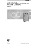
Varispeed V7
INSTRUCTION MANUAL
COMPACT GENERAL-PURPOSE INVERTER
(VOLTAGE VECTOR CONTROL)
FOR DeviceNet COMMUNICATIONS
Upon receipt of the product and prior to initial operation, read these instructions
thoroughly and retain them for future reference.
YASKAWA
MANUAL NO. TOE-S606-13C
PREFACE
Yaskawa’s Varispeed V7 is a small and simple Inverter; as easy to use as a
contactor. This instruction manual describes installation, maintenance,
inspection, troubleshooting, and specifications of the Varispeed V7. Read
this instruction manual thoroughly before operation.
YASKAWA ELECTRIC CORPORATION
General Precautions
• Some drawings in this manual are shown with protective covers or shields
removed in order to show detail with more clarity. Make sure all covers and
shields are replaced before operating the product.
• This manual may be modified when necessary because of improvements to
the product, modifications, or changes in specifications.
Such modifications are indicated by revising the manual number.
• To order a copy of this manual, or if your copy has been damaged or lost,
contact your Yaskawa representative.
• Yaskawa is not responsible for any modification of the product made by the
user, since that will void the guarantee.
1
NOTATION FOR SAFETY PRECAUTIONS
Read this instruction manual thoroughly before installation, operation, maintenance, or inspection of the Varispeed V7. In this manual, safety precautions are
classified as either warnings or cautions and are indicated as shown below.
WARNING
Indicates a potentially hazardous situation which, if not avoided, may result in
death or serious injury.
CAUTION
Indicates a potentially hazardous situation which, if not avoided, may result in
minor or moderate injury or damage to equipment.
It may also be used to alert against unsafe practices.
Even items classified as cautions may result in serious accidents in some situations. Always follow these important precautions.
NOTE
2
: Indicates information to insure proper operation.
PRECAUTIONS FOR UL/cUL MARKING
• Do not connect or disconnect wiring, or perform signal checks while the
power supply is turned ON.
• The Inverter internal capacitor is still charged even after the power supply
is turned OFF. To prevent electric shock, disconnect all power before servicing the Inverter, and then wait at least one minute after the power supply is disconnected. Confirm that all indicators are OFF before
proceeding.
• Do not perform a withstand voltage test on any part of the Inverter. The
Inverter is an electronic device that uses semiconductors, and is thus vulnerable to high voltage.
• Do not remove the Digital Operator or the blank cover unless the power
supply is turned OFF. Never touch the printed circuit board (PCB) while
the power supply is turned ON.
• This Inverter is not suitable for use on a circuit capable of delivering more
than 18,000 RMS symmetrical amperes, 250 V maximum (200 V Class
Inverters) or 18,000 RMS symmetrical amperes, 480 V maximum (400 V
Class Inverters).
CAUTION
• Use 75°C copper wire or equivalent.
Low voltage wires must be wired with Class I Wiring.
PRECAUTIONS FOR CE MARKINGS
• Only basic insulation to meet the requirements of protection class 1 and
overvoltage category II is provided with control circuit terminals.
Additional insulation may be necessary in the end product to conform to
CE requirements.
• For 400 V class Inverters, make sure to ground the supply neutral to conform to CE requirements.
• For conformance to EMC directives, refer to the relevant manuals for the
requirements.
Document No. EZZ008389 for Japanese version,
Document No. EZZ008390 for English version
3
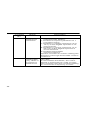
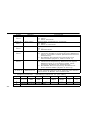
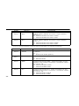
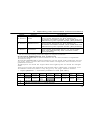
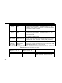
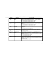
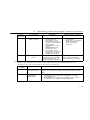
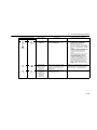
RECEIVING THE PRODUCT
CAUTION
(Ref. page)
• Do not install or operate any Inverter that is
damaged or has missing parts.
Failure to observe this caution may result in injury or
equipment damage.
19
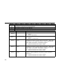
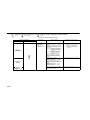
MOUNTING
CAUTION
(Ref. page)
4
• Lift the Inverter by the heatsinks. When moving
the Inverter, never lift it by the plastic case or the
terminal cover.
Otherwise, the main unit may fall and be damaged.
24
• Mount the Inverter on nonflammable material
(i.e., metal).
Failure to observe this caution may result in a fire.
24
• When mounting Inverters in an enclosure, install
a fan or other cooling device to keep the intake
air temperature below 50°C (122°F) for IP20
(open chassis type), or below 40°C (105°F) for
NEMA 1 (TYPE 1), IP20 (top closed type).
Overheating may cause a fire or damage the Inverter.
24
• The Varispeed V7 generates heat. For effective
cooling, mount it vertically.
Refer to the figure in Mounting Dimensions on
page 25.
25
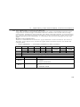
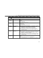
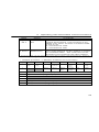
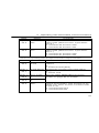
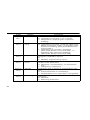
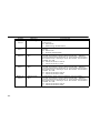
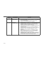
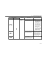
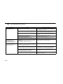
WIRING
WARNING
(Ref. page)
• Only begin wiring after verifying that the power
supply is turned OFF.
Failure to observe this warning may result in an electric shock or a fire.
28
• Wiring should be performed only by qualified
personnel.
Failure to observe this warning may Result in an
electric shock or a fire.
28
• When wiring the emergency stop circuit, check
the wiring thoroughly before operation.
Failure to observe this warning may result in injury.
28
• Always ground the ground terminal
36
.
(200 V Class: Ground to 100 Ω or less, 400 V
Class: Ground to 10 Ω or less)
Failure to observe this warning may Result in an
electric shock or a fire.
• For 400 V class, make sure to ground the supply neutral.
Failure to observe this warning may result in an electric shock or a fire.
28
• The motor will start automatically if the power
supply is turned ON while the RUN signal is ON.
Turn ON the power supply only after confirming
that the RUN signal is OFF.
Failure to observe this warning may result in injury.
40
• When the 3-wire sequence is set, do not make
the wiring for the control circuit unless the multifunction input terminal parameter is set.
Failure to observe this warning may result in injury.
159
5
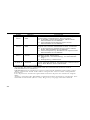
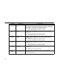
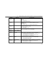
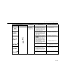
CAUTION
(Ref. page)
• Verify that the Inverter rated voltage coincides
with the AC power supply voltage.
Failure to observe this caution may result in personal
injury or a fire.
• Do not perform a withstand voltage test on the
Inverter.
Performing withstand voltage tests may damage
semiconductor elements.
• To connect a Braking Resistor, Braking Resistor
Unit, or Braking Unit, follow the procedure
described in this manual.
Improper connection may cause a fire.
36
• Always tighten terminal screws of the main circuit and the control circuits.
Failure to observe this caution may result in a malfunction, damage, or a fire.
28
• Never connect the AC main circuit power supply
to output terminals U/T1, V/T2, or W/T3.
The Inverter will be damaged and the guarantee will
be voided.
28
• Do not connect or disconnect wires or connectors while power is applied to the circuits.
Failure to observe this caution may result in injury.
• Do not perform signal checks during operation.
The machine or the Inverter may be damaged.
• To store the constant with an ENTER command
by communications, be sure to take measures
for an emergency stop by using the external terminals.
Delayed response may cause injury or damage the
machine.
6
126
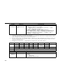
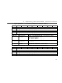
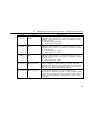
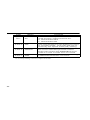
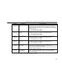
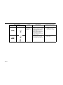
OPERATION
WARNING
(Ref. page)
• Only turn ON the input power supply after confirming that the Digital Operator or blank cover
(optional) are in place. Do not remove the
Digital Operator, remove the covers, or set
rotary switches while current is flowing.
Failure to observe this warning may result in an electric shock.
• Never operate the Digital Operator or DIP
switches with wet hands.
Failure to observe this warning may result in an electric shock.
• Never touch the terminals while current is flowing, even if the Inverter is stopping.
Failure to observe this warning may result in an electric shock.
• When the fault retry function is selected, stand
clear of the Inverter or the load. The Inverter
may restart suddenly after stopping.
(Construct the system to ensure safety, even if the
Inverter should restart.) Failure to observe this warning may result in injury.
148
• When continuous operation after power recovery is selected, stand clear of the Inverter or the
load. The Inverter may restart suddenly after
stopping.
(Construct the system to ensure safety, even if the
Inverter should restart.) Failure to observe this warning may result in injury.
144
• The Digital Operator stop button can be disabled by a setting in the Inverter. Install a separate emergency stop switch.
Failure to observe this warning may result in injury.
7
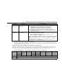
WARNING
(Ref. page)
• If an alarm is reset with the operation signal ON,
the Inverter will restart automatically. Reset an
alarm only after verifying that the operation signal is OFF.
Failure to observe this warning may result in injury.
40
• When the 3-wire sequence is set, do not make
the wiring for the control circuit unless the multifunction input terminal parameter is set.
Failure to observe this warning may result in injury.
159
CAUTION
(Ref. page)
• Never touch the heatsinks, which can be
extremely hot.
Failure to observe this caution may result in harmful
burns to the body.
• It is easy to change operation speed from low to
high. Verify the safe working range of the motor
and machine before operation.
Failure to observe this caution may result in injury
and machine damage.
• Install a holding brake separately if necessary.
Failure to observe this caution may result in injury.
• Do not perform signal checks during operation.
The machine or the Inverter may be damaged.
• All the constants set in the Inverter have been
preset at the factory. Do not change the settings
unnecessarily.
The Inverter may be damaged.
8
41
MAINTENANCE AND INSPECTION
WARNING
(Ref. page)
• Never touch high-voltage terminals on the
Inverter.
Failure to observe this warning may result in an electrical shock.
• Disconnect all power before performing maintenance or inspection, and then wait at least one
minute after the power supply is disconnected.
Confirm that all indicators are OFF before proceeding.
If the indicators are not OFF, the capacitors are still
charged and can be dangerous.
• Do not perform withstand voltage test on any
part of the Varispeed V7.
The Inverter is an electronic device that uses semiconductors, and is thus vulnerable to high voltage.
• Only authorized personnel should be permitted
to perform maintenance, inspection, or parts
replacement.
(Remove all metal objects (watches, bracelets, etc.)
before starting work.)
(Use tools which are insulated against electrical
shock.)
Failure to observe these warnings may result in an
electric shock.
202
9
CAUTION
(Ref. page)
• The control PCB employs CMOS ICs.
Do not touch the CMOS elements.
They are easily damaged by static electricity.
• Do not connect or disconnect wires, connectors,
or the cooling fan while power is applied to the
circuit.
Failure to observe this caution may result in injury.
202
OTHERS
WARNING
• Never modify the product.
Failure to observe this warning may result in an electrical shock or
injury and will void the guarantee.
CAUTION
• Do not subject the Inverter to halogen gases, such as fiuorine,
chlovine, bromine, and iodine, at any time even during transportation or installation.
Otherwise, the Inverter can be damaged or interior parts burnt.
10
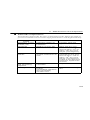
WARNING LABEL
A warning label is provided on the front cover of the Inverter, as shown below.
Follow the warnings when handling the Inverter.
Plastic Case
Status
Indicators
Warning Label Location
Nameplate
International Certification Marks
11
English and French Warning Labels
An English warning label is attached when the
Varispeed V7 is shipped.
If a Japanese or French label is required, attach
the warning label at the end of the Instruction
Manual over the Japanese warning label.
Warning Labels at End of Instruction Manual
English
French
Japanese
Warning Label
Example: 3-phase (200 V Class, 1.5 kW) Inverter
12
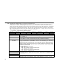
WARRANTY INFORMATION
Free Warranty Period and Scope
Warranty Period
This product is warranted for twelve months after being delivered to
Yaskawa’s customer or if applicable eighteen months from the date of
shipment from Yaskawa’s factory, whichever comes first.
Scope of Warranty
Inspections
Periodic inspections must be conducted by the customer. However,
upon request, Yaskawa or one of Yaskawa’s Service Centers can inspect
the product for a fee. In this case, if after conferring with the customer, a
Yaskawa product is found to be defective due to Yaskawa workmanship
or materials and the defect occurs during the warranty period, then this
fee will be waived and the problem remedied free of charge.
Repairs
If a Yaskawa product is found to be defective due to Yaskawa workmanship or materials and the defect occurs during the warranty period,
Yaskawa will provide a replacement, repair the defective product, and
provide shipping to and from the site free of charge.
However, if the Yaskawa Authorized Service Center determines that the
problem with a Yaskawa product is not due to defects in Yaskawa’s
workmanship or materials, then the customer will be responsible for the
cost of any necessary repairs. Some problems that are outside the scope
of this warranty are:
• Problems due to improper maintenance or handling, carelessness, or
other reasons where the customer is determined to be responsible.
• Problems due to additions or modifications made to a Yaskawa product without Yaskawa’s understanding.
• Problems due to the use of a Yaskawa product under conditions that
do not meet the recommended specifications.
• Problems caused by natural disaster or fire.
• Or other problems not due to defects in Yaskawa workmanship or
materials.
Warranty service is only applicable within Japan.
However, after-sales service is available for customers outside of Japan
for a reasonable fee. Contact your local Yaskawa representative for
more information.
13
Exceptions
Any inconvenience to the customer or damage to non-Yaskawa products
due to Yaskawa's defective products whether within or outside the warranty period are NOT covered by this warranty.
RESTRICTIONS
• The Varispeed V7 was not designed or manufactured for use in devices or
systems that may directly affect or threaten human lives or health.
• Customers who intend to use the product described in this manual for
devices or systems relating to transportation, health care, space aviation,
atomic or electric power, or underwater use must contact their Yaskawa
representatives or the nearest Yaskawa sales office beforehand.
• This product has been manufactured under strict quality-control guidelines. However, if this product is to be installed in any location where failure of this product could involve or result in a life-and-death situation or
loss of human life or in a facility where failure may cause a serious accident or physical injury, safety devices must be installed to minimize the
likelihood of any accident.
14
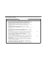
CONTENTS
NOTATION FOR SAFETY PRECAUTIONS - - - - - - 2
1. Receiving the Product - - - - - - - - - - - - - - - - - - - 19
■ Checking the Nameplate - - - - - - - - - - - - - - - - - - - - - - - - - - - 20
2. Identifying the Parts - - - - - - - - - - - - - - - - - - - - 21
3. Mounting - - - - - - - - - - - - - - - - - - - - - - - - - - - - 24
■ Choosing a Location to Mount the Inverter - - - - - - - - - - - - - - 24
■ Mounting Dimensions - - - - - - - - - - - - - - - - - - - - - - - - - - - - - 25
■ Mounting/Removing Components- - - - - - - - - - - - - - - - - - - - - 26
4. Wiring - - - - - - - - - - - - - - - - - - - - - - - - - - - - - - 28
■ Wiring Instructions - - - - - - - - - - - - - - - - - - - - - - - - - - - - - - ■ Wire and Terminal Screw Sizes - - - - - - - - - - - - - - - - - - - - - ■ Wiring the Main Circuits- - - - - - - - - - - - - - - - - - - - - - - - - - - ■ Wiring the Control Circuits - - - - - - - - - - - - - - - - - - - - - - - - - ■ Wiring the DeviceNet Communications Cable - - - - - - - - - - - ■ Wiring Inspection - - - - - - - - - - - - - - - - - - - - - - - - - - - - - - - -
29
30
36
38
39
40
5. Operating the Inverter - - - - - - - - - - - - - - - - - - - 41
■ Test Run - - - - - - - - - - - - - - - - - - - - - - - - - - - - - - - - - - - - - - 42
Operation Check Points- - - - - - - - - - - - - - - - - - - - - - - - - - - - 43
■ Operating the Digital Operator - - - - - - - - - - - - - - - - - - - - - - - 44
Description of Status Indicators - - - - - - - - - - - - - - - - - - - - - - 45
■ Function Indicator Description - - - - - - - - - - - - - - - - - - - - - - - 47
MNTR Multi-function Monitoring - - - - - - - - - - - - - - - - - - - - - - 48
Input/Output Terminal Status - - - - - - - - - - - - - - - - - - - - - - - - 51
■ Simple Data Setting - - - - - - - - - - - - - - - - - - - - - - - - - - - - - - 53
6. Operating with DeviceNet Communications - - - 55
■ Specifications - - - - - - - - - - - - - - - - - - - - - - - - - - - - - - - - - - - 55
■ Component Names and Settings - - - - - - - - - - - - - - - - - - - - - 56
15
Rotary Switches - - - - - - - - - - - - - - - - - - - - - - - - - - - - - - - - - 56
■ Description of the DeviceNet Functions - - - - - - - - - - - - - - - - - 57
Initial Settings - - - - - - - - - - - - - - - - - - - - - - - - - - - - - - - - - - - 57
I/O Message Communications - - - - - - - - - - - - - - - - - - - - - - - 59
Explicit Message Communications - - - - - - - - - - - - - - - - - - - - 94
■ Error Code Tables - - - - - - - - - - - - - - - - - - - - - - - - - - - - - - - 116
Explicit Message Communications Errors - - - - - - - - - - - - - - 116
MEMOBUS I/O Instance Error Table - - - - - - - - - - - - - - - - - - 117
■ MEMOBUS Register Tables - - - - - - - - - - - - - - - - - - - - - - - - 119
7. Programming Features - - - - - - - - - - - - - - - - - 127
■ Constant Setup and Initialization - - - - - - - - - - - - - - - - - - - - - 127
Constant Selection/Initialization (n001) - - - - - - - - - - - - - - - - 127
■ Using V/f Control Mode - - - - - - - - - - - - - - - - - - - - - - - - - - - 129
Adjusting Torque According to Application - - - - - - - - - - - - - - 129
■ Using Vector Control Mode - - - - - - - - - - - - - - - - - - - - - - - - - 132
Precautions for Voltage Vector Control Application - - - - - - - - 132
Motor Constant Calculation- - - - - - - - - - - - - - - - - - - - - - - - - 133
V/f Pattern during Vector Control - - - - - - - - - - - - - - - - - - - - - 134
■ Switching LOCAL/REMOTE Mode - - - - - - - - - - - - - - - - - - - 135
How to Select LOCAL/REMOTE Mode - - - - - - - - - - - - - - - - 136
■ Selecting RUN/STOP Commands - - - - - - - - - - - - - - - - - - - - 136
LOCAL Mode - - - - - - - - - - - - - - - - - - - - - - - - - - - - - - - - - - 136
REMOTE Mode - - - - - - - - - - - - - - - - - - - - - - - - - - - - - - - - - 137
Operating (RUN/STOP Commands) Using DeviceNet
Communications - - - - - - - - - - - - - - - - - - - - - - - - - - - - - - - - 137
■ Selecting Frequency Reference - - - - - - - - - - - - - - - - - - - - - 137
LOCAL Mode - - - - - - - - - - - - - - - - - - - - - - - - - - - - - - - - - - 137
REMOTE Mode - - - - - - - - - - - - - - - - - - - - - - - - - - - - - - - - - 138
■ Setting Operation Conditions - - - - - - - - - - - - - - - - - - - - - - - 139
16
Reverse Run Prohibit (n006)- - - - - - - - - - - - - - - - - - - - - - - - 139
Multi-step Speed Selection - - - - - - - - - - - - - - - - - - - - - - - - - 139
Operating at Low Speed - - - - - - - - - - - - - - - - - - - - - - - - - - - 141
Adjusting Speed Setting Signal - - - - - - - - - - - - - - - - - - - - - - 141
Adjusitng Frequency Upper and Lower Limits- - - - - - - - - - - - 142
Using Two Acceleration/Deceleration Times - - - - - - - - - - - - 143
Momentary Power Loss Ridethrough Method (n081) - - - - - - 144
S-curve Selection (n023) - - - - - - - - - - - - - - - - - - - - - - - - - - 145
Torque Detection - - - - - - - - - - - - - - - - - - - - - - - - - - - - - - - 146
Frequency Detection Level (n095) - - - - - - - - - - - - - - - - - - - 147
Jump Frequencies (n083 to n086) - - - - - - - - - - - - - - - - - - - 148
Continuing Operation Using Automatic Retry Attempts (n082) 148
Operating a Coasting Motor without Tripping - - - - - - - - - - - - 149
Holding Acceleration/Deceleration Temporarily - - - - - - - - - - 150
Reducing Motor Noise or Leakage Current Using Carrier
Frequency Selection (n080) - - - - - - - - - - - - - - - - - - - - - - - - 151
Operator Stop Key Selection (n007) - - - - - - - - - - - - - - - - - - 154
■ Selecting the Stopping Method- - - - - - - - - - - - - - - - - - - - - - 155
Stopping Method Selection (n005) - - - - - - - - - - - - - - - - - - - 155
Applying DC Injection Braking - - - - - - - - - - - - - - - - - - - - - - 156
■ Building Interface Circuits with External Devices - - - - - - - - - 157
Using Input Signals - - - - - - - - - - - - - - - - - - - - - - - - - - - - - - 157
Using the Multi-function Analog Inputs (n077, n078)- - - - - - - 162
Using Output Signals (n057, n058, n059) - - - - - - - - - - - - - - 164
■ Preventing the Motor from Stalling (Current Limit) - - - - - - - - 167
Stall Prevention during Operation - - - - - - - - - - - - - - - - - - - - 169
■ Decreasing Motor Speed Fluctuation - - - - - - - - - - - - - - - - - 171
Slip Compensation (n002 = 0) - - - - - - - - - - - - - - - - - - - - - - 171
■ Motor Protection - - - - - - - - - - - - - - - - - - - - - - - - - - - - - - - - 172
Motor Overload Detection - - - - - - - - - - - - - - - - - - - - - - - - - 172
■ Selecting Cooling Fan Operation - - - - - - - - - - - - - - - - - - - - 174
■ Using Energy-saving Control Mode - - - - - - - - - - - - - - - - - - 174
Energy-saving Control Selection (n139) - - - - - - - - - - - - - - - 174
Energy-saving Search Operation - - - - - - - - - - - - - - - - - - - - 176
Motor Code - - - - - - - - - - - - - - - - - - - - - - - - - - - - - - - - - - - 178
■ Using PID Control Mode - - - - - - - - - - - - - - - - - - - - - - - - - - 179
PID Control Selection (n128) - - - - - - - - - - - - - - - - - - - - - - - 179
■ Using Constant Copy Function- - - - - - - - - - - - - - - - - - - - - - 186
Constant Copy Function - - - - - - - - - - - - - - - - - - - - - - - - - - 186
READ Function- - - - - - - - - - - - - - - - - - - - - - - - - - - - - - - - - 188
17
COPY Function - - - - - - - - - - - - - - - - - - - - - - - - - - - - - - - - - 189
VERIFY Function- - - - - - - - - - - - - - - - - - - - - - - - - - - - - - - - 190
Inverter Capacity Display - - - - - - - - - - - - - - - - - - - - - - - - - - 192
Software No. Display - - - - - - - - - - - - - - - - - - - - - - - - - - - - - 194
Display List - - - - - - - - - - - - - - - - - - - - - - - - - - - - - - - - - - - - 194
■ Unit Selection for Frequency Reference Setting/Display - - - - 196
■ Selecting Processing for Frequency Reference Loss (n064) - 198
■ Input/Output Open-phase Detection - - - - - - - - - - - - - - - - - - 199
■ Undertorque Detection - - - - - - - - - - - - - - - - - - - - - - - - - - - - 200
8. Maintenance and Inspection - - - - - - - - - - - - - 202
■ Periodic Inspection - - - - - - - - - - - - - - - - - - - - - - - - - - - - - - 203
■ Part Replacement - - - - - - - - - - - - - - - - - - - - - - - - - - - - - - - 204
Replacement of Cooling Fan- - - - - - - - - - - - - - - - - - - - - - - - 205
9. Fault Diagnosis - - - - - - - - - - - - - - - - - - - - - - 207
■ Protective and Diagnostic Functions - - - - - - - - - - - - - - - - - - 207
Corrective Actions of Models with Blank Cover - - - - - - - - - - - 207
Corrective Actions of Models with Digital Operator - - - - - - - - 208
Errors Indicated by the DeviceNet Communications
Indicators - - - - - - - - - - - - - - - - - - - - - - - - - - - - - - - - - - - - - 218
■ Troubleshooting- - - - - - - - - - - - - - - - - - - - - - - - - - - - - - - - - 220
10. Specifications - - - - - - - - - - - - - - - - - - - - - - - 223
■ Standard Specifications (200 V Class) - - - - - - - - - - - - - - - - - 223
■ Standard Specifications (400 V Class) - - - - - - - - - - - - - - - - - 227
■ Standard Wiring- - - - - - - - - - - - - - - - - - - - - - - - - - - - - - - - - 231
■ Sequence Input Connection with NPN/PNP Transistor - - - - - 234
■ Dimensions/Heat Loss (Unit: mm) - - - - - - - - - - - - - - - - - - - - 236
■ Recommended Peripheral Devices - - - - - - - - - - - - - - - - - - - 239
■ Constants List - - - - - - - - - - - - - - - - - - - - - - - - - - - - - - - - - - 242
Revision History
18
1. Receiving the Product
1. Receiving the Product
CAUTION Do not install or operate any Inverter that is damaged or
has missing parts.
Failure to observe this caution may result in injury or
equipment damage.
After unpacking the Varispeed V7, check the following.
• Verify that the model number matches your purchase order or packing
slip.
• Check the Inverter for physical damage that may have occurred during
shipping.
If any part of Varispeed V7 is missing or damaged, call for service immediately.
19
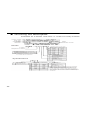
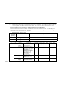
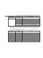
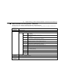
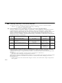
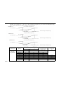
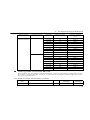
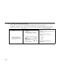
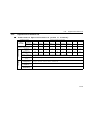
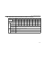
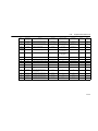
Checking the Nameplate
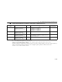
Example for 3-phase, 200-VAC, 0.1-kW (0.13-HP) Inverter
Inverter model
Input spec.
Output spec.
Lot No.
Serial No.
CIMR-V7NA20P1
Mass
Software number
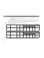
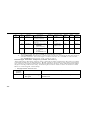
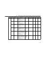
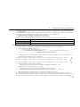
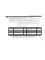
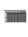
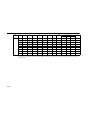
Model
NA
Applicable maximum motor output
200 V class
400 V class
0.1 kW
0.25 kW
0.37 kW
0.55 kW
0.55 kW
1.1 kW
1.1 kW
1.5 kW
1.5 kW
2.2 kW
2.2 kW
3.0 kW
3.7 kW
3.7 kW
5.5 kW
5.5 kW
7.5 kW
7.5 kW
Inverter
OP1
Varispeed V7 Series
OP2
OP4
OP7
No.
N
M
P
Type
With Digital Operator (with potentiometer)
With Digital Operator (without potentiometer)
Without Digital Operator
Note: Contact your Yaskawa representatives
for models without heatsinks.
1P5
2P2
3P0
3P7
5P5
7P5
No.
B
2
4
No.
A
C
U
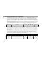
Specifications
B
2
4
Single-phase 200 VAC
Three-phase 200 VAC
Three-phase 400 VAC
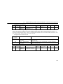
Applicable maximum motor output
200 V class
400 V class
0.1 kW
0.25 kW
0.37 kW
OP4
0.55 kW
0.55 kW
OP7
1.1 kW
1.1 kW
1P5
1.5 kW
1.5 kW
2P2
2.2 kW
2.2 kW
3P0
3.0 kW
3P7
3.7 kW
3.7 kW
5P5
5.5 kW
5.5 kW
7P5
7.5 kW
7.5 kW
OP1
OP2
20
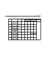
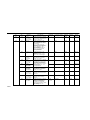
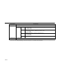
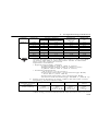
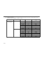
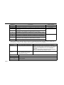
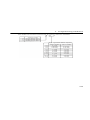
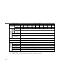
No.
0
Voltage Class
Single-phase 200 VAC
Three-phase 200 VAC
Three-phase 400 VAC
Specifications
Standard
European standards
American standards
Protective structure
Open chassis
(IP20)*1
1
Enclosed wall-mounted
(NEMA1)*2
7
Open chassis (IP20, IP00)*1
top-closed type
*1 These OP1 to 3P7 Inverters meet IP20 standards.
When mounting the 5P5 and 7P5 Inverters in a
panel, always remove the top and bottom covers.
(In this case, the Inverter meets IP00 standards.)
2
* These OP1 to 3P7 Inverters have the NEMA1 option.
The standard 5P5 and 7P5 Inverters meet NEMA1
standards.
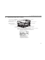
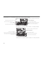
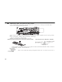
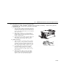
2. Identifying the Parts
2. Identifying the Parts
Terminal Cover
DeviceNet Communications Cable Hole
Digital Operator
Opening for Control
Circuit Wiring
Front Cover
Opening for Main
Circuit Wiring
Nameplate
Ground Terminal
Heatsink
Cooling Fan
Cooling Fan Cover
Bottom Cover
Ground wire connecting DeviceNet communications
cable’s shield to ground terminal
Note: The wire connects the shield to the
ground terminal inside inverters of
5.5 kW or 7.5 kW.
Digital operator
(with potentiometer)
JVOP-140U
sed for setting or
changing constants.
Frequency can be set
using potentiometer.
21
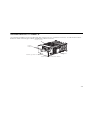
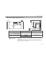
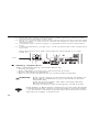
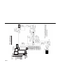
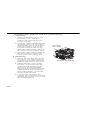
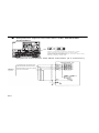
Varispeed V7 Inverters with the Covers Removed
Frequency Setting Potentiometer
Inverter Operation
Status Indicators
Baud Rate Setting Switch
MAC ID Setting Switches
Input Polarity Switch
Jumper Bar
Control Circuit Terminal Block
Main Circuit Terminal Block
DeviceNet Terminal Block
Ground Terminals
Example for 3-phase (200 V Class, 1.5 kW) Inverter
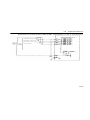
Frequency Setting Potentiometer
Inverter Operation
Status Indicators
Baud Rate Setting
Switch
Input Polarity Switch
MAC ID Setting Switches
Control Circuit Terminal Block
DeviceNet Terminal Block
Jumper Bar
Main Circuit Terminal Block
Ground Terminals
Example for 3-phase (200 V Class, 0.1 kW) Inverter
22
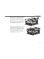
2. Identifying the Parts
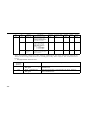
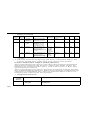
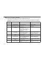
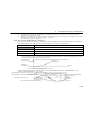
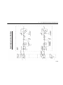
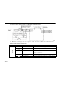
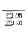
Main Circuit Terminal Arrangement
The terminal arrangement of the main circuit terminals depends on the
Inverter model.
CIMR-V7
20P1 to 20P7, B0P1 to B0P4
CIMR-V7
21P5, 22P2, B0P7, B1P5, 40P2 to 42P2
CIMR-V7
24P0, B2P2, 43P0, 43P7
CIMR-V7
B3P7
CIMR-V7
25P5, 27P5, 45P5, 47P5
23
3. Mounting
Choosing a Location to Mount the Inverter
Be sure the Inverter is protected from the following conditions.
• Extreme cold and heat. Use only within the specified ambient temperature range:
−10 to 50°C (14 to 122°F) for IP20 (open chassis type),
−10 to 40°C (14 to 105°F) for NEMA 11 (TYPE 1), IP 20 (top
closed type)
• Rain and moisture
• Oil sprays and splashes
• Salt spray
• Direct sunlight (Avoid using outdoors.)
• Corrosive gases (e.g., sulfurized gas) or liquids
• Dust or metallic particles in the air
• Physical shock or vibration
• Magnetic noise (Examples: Welding machines, power devices, etc.)
• High humidity
• Radioactive substances
• Combustibles, such as thinner or solvents
24
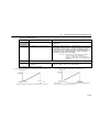
3. Mounting
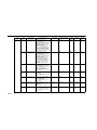
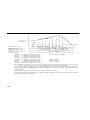
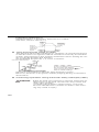
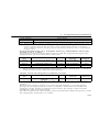
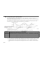
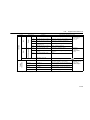
Mounting Dimensions
To mount the Varispeed V7, the dimensions shown below are required.
a
a
100 mm (3.94 in.)
min.
100 mm (3.94 in.)
min.
Air
Air
Voltage Class
Max. Applicable
Motor Capacity
Distance “a”
200 V, Single phase
or Three phase
400 V, Three phase
3.7 kW max.
30 mm min.
200 V, Three phase
400 V, Three phase
5.5 kW
50 mm min.
7.5 kW
CAUTION • Lift the Inverter by the heatsinks. When moving the
Inverter, never lift it by the plastic case or the terminal cover.
Otherwise, the main unit may fall and be damaged.
• The Varispeed V7 generates heat. For effective cooling, mount it vertically.
25
IMPORTANT
• The dimensions shown for the distances on the left/right
and top/bottom of the Inverter apply to both mounting
within a panel (IP00 and IP20) and enclosed models
(NEMA1).
• When operating a 5.5-kW or 7.5-kW Inverter (200 V or
400 V Class) within a panel, always remove the top and
bottom covers.
Mounting/Removing Components
Removing and Mounting the Digital Operator and Covers
• Removing the Front Cover
Use a screwdriver to loosen the
screw on the front cover and
then remove it in direction 1.
Then press the right and left
sides in direction 2 and lift the
front cover in direction 3.
1
2
3
2
• Mounting the Front Cover
Mount the front cover by reversing the order of the above procedure for removal.
• Removing the Terminal Cover
After removing the front cover,
press the right and left sides of
the terminal cover in direction 1
and lift the terminal cover in
direction 2.
• Mounting the Terminal Cover
Mount the terminal cover by
reversing the order of the above
procedure for removal.
26
1
2
1
3. Mounting
• Removing the Digital Operator
After removing the front cover,
lift the upper and lower sides
(section A) of the right side of
the Digital Operator in direction
1.
A
A
• Mounting the Digital Operator
Mount the Digital Operator by
reversing the order of the above
procedure for removal.
• Removing the Bottom Cover
After removing the front cover
and the terminal cover, tilt the
bottom cover in direction 1 with
section A as a supporting point.
• Mounting the Bottom Cover A
Mount the bottom cover by
reversing the order of the above
A
procedure for removal.
27
4. Wiring
WARNING • Only begin wiring after verifying that the power supply is turned OFF.
Failure to observe this warning may result in an
electric shock or a fire.
• Wiring should be performed only by qualified personnel.
Failure to observe this warning may result in an
electric shock or a fire.
• When wiring the emergency stop circuit, check the
wiring thoroughly before operation.
Failure to observe this warning may result in injury.
• For 400 V class, make sure to ground the supply
neutral.
Failure to observe this warning may result in an
electric shock or a fire.
CAUTION
28
• Verify that the Inverter rated voltage coincides with
the AC power supply voltage.
Failure to observe this caution may result in personal injury or a fire.
• Do not perform a withstand voltage test on the
Inverter.
Performing withstand voltage tests may damage
semiconductor elements.
• Always tighten terminal screws of the main circuit
and the control circuits.
Failure to observe this caution may result in a malfunction, damage, or a fire.
• Never connect the AC main circuit power supply to
output terminals U/T1, V/T2, W/T3, B1, B2, −, +1,
or +2.
The Inverter will be damaged and the guarantee will
be voided.
• Do not connect or disconnect wires or connectors
while power is applied to the circuits.
Failure to observe this caution may result in injury.
• Do not perform signal checks during operation.
The machine or the Inverter may be damaged.
• To store the constant with an ENTER command by
communications, be sure to take measures for an
4. Wiring
emergency stop by using the external terminals.
Delayed response may cause injury or damage the
machine.
Wiring Instructions
1. Always connect the power supply for the main circuit inputs to the
power input terminals R/L1, S/L2, and T/L3 (R/L1, S/L2 for singlephase power) via a molded-case circuit breaker (MCCB) or a fuse.
Never connect the power supply to terminals U/T1, V/T2, W/T3, B1,
B2, −, +1, or +2. The Inverter may be damaged.
For 200 V single-phase Inverters, always use terminals R/L1 and S/
L2. Never connect terminal T/L3.
Refer to page 239 for recommended peripheral devices.
Use a UL class RK5 fuse. For single-phase, 200-V Inverters of
075 kW or less, a 3-phase, 200-V power supply can also be connected.
Inverter Power Supply Connection Terminals
200-V 3-phase Input
Power Supply Specification Inverters
CIMR-V72
200-V Single Input
Power Supply Specification Inverters
CIMR-V7B
400-V 3-phase Input
Power Supply Specification Inverters
CIMR-V74
Connect to R/L1,
S/L2, and T/L3.
Connect to R/L1 and
S/L2.
Connect to R/L1,
S/L2, and T/L3.
2. If the wiring distance between Inverter and motor is long, reduce the
Inverter carrier frequency. For details, refer to Reducing Motor
Noise or Leakage Current (n080) on page 151. Control wiring must
be less than 50 m (164 ft) in length and must be separated from
power wiring. Use shielded twisted-pair cable when inputting the
frequency signal externally.
3. For 400 V Class Inverters, always ground the supply neutral to conform to CE requirements.
4. Closed-loop connectors should be used when wiring to the main circuit terminals.
29
5. Voltage drop should be considered when determining the wire size.
Voltage drop can be calculated using the following equation:
Phase-to-phase voltage drop (V)
=
3 × wire resistance (Ω/km) × wiring distance (m) × current
(A) × 10-3
Select a wire size so that voltage drop will be less than 2% of the
normal rated voltage. Increase the wire size according to the length
of the cable if there is a possibility that the voltage may drop.
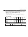
Wire and Terminal Screw Sizes
1. Control Circuits
Model
Same for
all models
Terminal Symbols
S1 to S4, P1, P2,
SC, PC
Screws
M2
Tightening
Torque
N•m
(lb•in)
0.22 to
0.25
(1.94 to
2.21)
Wires
Applicable Size
Recommended Size
mm2
AWG
mm2
AWG
Twisted
wires:
0.5 to
0.75,
Single:
0.5 to
1.25
20 to
18,
20 to
16
0.75
18
Type
Shielded
or equivalent
2. DeviceNet Terminal Block (CN6)
Model
Same for
all models
Terminal Symbols
V−, CAN_L,
shield, CAN_H,
V+
Screws
M3
Tightening
Torque
N•m
(lb•in)
0.5 to
0.6
Wires
Applicable Size
mm2
AWG
Twisted
wires:
0.2 to
2.5
24 to
12
Recommended Size
mm2
Type
AWG
Thin
DeviceNet
cable that
meets
DeviceNet
cable
specifications
Note: When removing the DeviceNet terminal block, hold the control circuit
terminal block (TB1).
30
4. Wiring
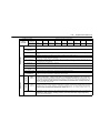
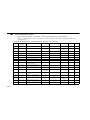
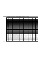
3. Main Circuits
200 V Class 3-phase Input Inverters
Model
Terminal Symbols
Screws
Tightening
Torque
N•m
(lb•in)
Wires
Applicable Size
Recommended
Size
mm2
AWG
mm2
AWG
CIMRV7∗∗
20P1
R/L1, S/L2, T/L3,
-, +1, +2, B1, B2,
U/T1, V/T2, W/T3
M3.5
0.8 to
1.0 (7.1
to 8.88)
0.75
to 2
18 to
14
2
14
CIMRV7∗∗
20P2
R/L1, S/L2, T/L3,
-, +1, +2, B1, B2,
U/T1, V/T2, W/T3
M3.5
0.8 to
1.0 (7.1
to 8.88)
0.75
to 2
18 to
14
2
14
CIMRV7∗∗
20P4
R/L1, S/L2, T/L3,
-, +1, +2, B1, B2,
U/T1, V/T2, W/T3
M3.5
0.8 to
1.0 (7.1
to 8.88)
0.75
to 2
18 to
14
2
14
CIMRV7∗∗
20P7
R/L1, S/L2, T/L3,
-, +1, +2, B1, B2,
U/T1, V/T2, W/T3
M3.5
0.8 to
1.0 (7.1
to 8.88)
0.75
to 2
18 to
14
2
14
CIMRV7∗∗
21P5
R/L1, S/L2, T/L3,
-, +1, +2, B1, B2,
U/T1, V/T2, W/T3
M4
1.2 to
1.5
(10.65
to
13.31)
2 to
5.5
14 to
10
2
14
3.5
12
CIMRV7∗∗
22P2
R/L1, S/L2, T/L3,
-, +1, +2, B1, B2,
U/T1, V/T2, W/T3
M4
1.2 to
1.5
(10.65
to
13.31)
2 to
5.5
14 to
10
3.5
12
CIMRV7∗∗
23P7
R/L1, S/L2, T/L3,
-, +1, +2, B1, B2,
U/T1, V/T2, W/T3
M4
1.2 to
1.5
(10.65
to
13.31)
2 to
5.5
14 to
10
5.5
10
Type
600 V
vinylsheathed
or equivalent
Note: The wire size is given for copper wire at 75°C (160°F).
31
200 V Class Single-phase Input Inverters
Model
32
Terminal Symbols
Screws
Tightening
Torque
N•m
(lb•in)
Wires
Applicable Size
Recommended
Size
mm2
AWG
mm2
AWG
CIMRV7∗∗
B0P1
R/L1, S/L2, T/L3,
-, +1, +2, B1, B2,
U/T1, V/T2, W/T3
M3.5
0.8 to
1.0 (7.1
to 8.88)
0.75 to
2
18 to
14
2
14
CIMRV7∗∗
B0P2
R/L1, S/L2, T/L3,
-, +1, +2, B1, B2,
U/T1, V/T2, W/T3
M3.5
0.8 to
1.0 (7.1
to 8.88)
0.75 to
2
18 to
14
2
14
CIMRV7∗∗
B0P4
R/L1, S/L2, T/L3,
-, +1, +2, B1, B2,
U/T1, V/T2, W/T3
M3.5
0.8 to
1.0 (7.1
to 8.88)
0.75 to
2
18 to
14
2
14
CIMRV7∗∗
B0P7
R/L1, S/L2, T/L3,
-, +1, +2, B1, B2,
U/T1, V/T2, W/T3
M4
1.2 to
1.5
(10.65
to
13.31)
2 to
5.5
14 to
10
3.5
12
CIMRV7∗∗
B1P5
R/L1, S/L2, -, +1,
+2, B1, B2, U/T1,
V/T2, W/T3
M4
1.2 to
1.5
(10.65
to
13.31)
2 to
5.5
14 to
10
5.5
10
CIMRV7∗∗
B2P2
R/L1, S/L2, -, +1,
+2, B1, B2, U/T1,
V/T2, W/T3
M4
1.2 to
1.5
(10.65
to
13.31)
2 to
5.5
14 to
10
5.5
10
CIMRV7∗∗
B3P7
R/L1, S/L2, -, +1,
+2, B1, B2, U/T1,
V/T2, W/T3
M5
3.0
(26.62)
3.5 to
8
12 to 8
8
8
M4
1.2 to
1.5
(10.65
to
13.31)
2 to 8
14 to
10
Type
600 V
vinylsheathed
or equivalent
4. Wiring
Model
Terminal Symbols
Screws
Tightening
Torque
N•m
(lb•in)
Wires
Applicable Size
Recommended
Size
mm
AWG
CIMRV7∗A
25P5
R/L1, S/L2, T/L3,
-, +1, +2, B1, B2,
U/T1, V/T2, W/T3
M5
2.5
5.5 to
8
10 to 8
8
8
CIMRV7∗A
27P5
R/L1, S/L2, T/L3,
-, +1, +2, B1, B2,
U/T1, V/T2, W/T3
M5
2.5
5.5 to
8
10 to 8
8
8
2
mm
2
Type
AWG
600 V
vinylsheathed
wire or
equivalent
Note: 1. The wire size is given for copper wire at 75°C (160°F).
2. Three-phase power can also be input for 0.1 to 1.1-kW, Single-phase
Input Inverters.
33
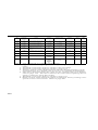
400 V Class 3-phase Input Inverters
Model
Screws
Tightening
Torque
N•m
(lb•in)
Wires
Applicable Size
Recommended
Size
mm2
AWG
mm2
AWG
CIMRV7∗∗
40P2
R/L1, S/L2, T/L3,
-, +1, +2, B1, B2,
U/T1, V/T2, W/T3
M4
1.2 to
1.5
(10.65
to
13.31)
2 to
5.5
14 to
10
2
14
CIMRV7∗∗
40P4
R/L1, S/L2, T/L3,
-, +1, +2, B1, B2,
U/T1, V/T2, W/T3
M4
1.2 to
1.5
(10.65
to
13.31)
2 to
5.5
14 to
10
2
14
CIMRV7∗∗
40P7
R/L1, S/L2, T/L3,
-, +1, +2, B1, B2,
U/T1, V/T2, W/T3
M4
1.2 to
1.5
(10.65
to
13.31)
2 to
5.5
14 to
10
2
14
CIMRV7∗∗
41P5
R/L1, S/L2, T/L3,
-, +1, +2, B1, B2,
U/T1, V/T2, W/T3
M4
1.2 to
1.5
(10.65
to
13.31)
2 to
5.5
14 to
10
2
14
CIMRV7∗∗
42P2
R/L1, S/L2, T/L3,
-, +1, +2, B1, B2,
U/T1, V/T2, W/T3
M4
1.2 to
1.5
(10.65
to
13.31)
2 to
5.5
14 to
10
2
14
CIMRV7∗∗
43P0
R/L1, S/L2, T/L3,
-, +1, +2, B1, B2,
U/T1, V/T2, W/T3
M4
1.2 to
1.5
(10.65
to
13.31)
2 to
5.5
14 to
10
2
14
3.5
12
1.2 to
1.5
(10.65
to
13.31)
2 to
5.5
2
14
3.5
12
1.4
3.5 to
5.5
5.5
10
CIMRV7∗∗
43P7
CIMRV7∗A
45P5
34
Terminal Symbols
R/L1, S/L2, T/L3,
-, +1, +2, B1, B2,
U/T1, V/T2, W/T3
R/L1, S/L2, T/L3,
-, +1, +2, B1, B2,
U/T1, V/T2, W/T3
M4
M4
14 to
10
12 to
10
Type
600 V
vinylsheathed
or equivalent
4. Wiring
Model
Terminal Symbols
Screws
Tightening
Torque
N•m
(lb•in)
Wires
Applicable Size
mm
CIMRV7∗A
47P5
R/L1, S/L2, T/L3,
-, +1, +2, B1, B2,
U/T1, V/T2, W/T3
M5
2.5
2
5.5 to
8
Recommended
Size
AWG
mm
10 to 8
5.5
2
Type
AWG
10
600 V
vinylsheathed
wire or
equivalent
Note: The wire size is given for copper wire at 75°C (160°F).
35
Wiring the Main Circuits
RST
Circuit Breaker
for Wiring
Ground
• Main Circuit Input Power Supply
Always connect the power supply line to input terminals R/L1, S/L2, and T/L3 (R/L1, S/
L2 for single-phase Inverters). Never connect them to terminals U/T1, V/T2, W/T3, B1,
B2, −, +1, or +2. The Inverter may be damaged if the wrong terminals are connected.
For single-phase Inverters, always use terminals R/L1 and S/L2. Never connect
NOTE terminal T/L3.
• Grounding (Use ground terminal
WARNING
.)
Always ground the ground terminal
according to local
grounding codes.
Failure to observe this warning may result in an electric shock
or a fire.
Never ground the Varispeed V7 to the same ground as welding machines, motors, or other
electrical equipment.
When several Varispeed V7 Inverters are used side by side, ground each as shown in examples. Do not loop the ground wires.
Good
36
Good
Poor
4. Wiring
• Braking Resistor Connection (Optional)
WARNING
To connect the braking resistor, cut the protector on terminals
B1 and B2.
To protect the braking resistor from overheating, install a thermal overload relay between the braking resistor and the
Inverter. This provides a sequence that turns OFF the power
supply with thermal relay trip contacts.
Failure to observe this warning may result in a fire.
Use this same procedure when connecting a Braking Resistor Unit.
Refer to page 232.
• Inverter Output
Connect the motor terminals to U/T1, V/T2, and W/T3.
• Wiring the Main Circuit Terminals
Pass the cables through wiring hole to connect them. Always mount the cover in its original position.
Connect with a Phillips screwdriver.
37
Wiring the Control Circuits
Pass the cable through wiring hole to connect it. Always mount the
cover in its original position.
S2 can be changed according to sequence input signal (S1 to S7) polarity.
0 V common: NPN side (Factory setting)
+24 V common: PNP side
Refer to pages 234 and 235 for S2.
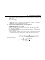
Wiring the Control Circuit Terminals
Screwdriver Blade Width
0.4 mm max
(0.016 in.)
2.5 mm max
(0.098 in.)
Insert the wire into the lower part of the terminal block and connect
it tightly with a screwdriver.
5.5 mm
(0.22 in.)
The wire sheath strip length must be 5.5 mm (0.22 in.).
38
4. Wiring
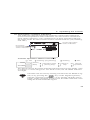
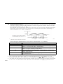
Wiring the DeviceNet Communications Cable
Use the following procedure to wire the DeviceNet communications
cable to the terminal block (CN6).
1. Use a thin slotted screwdriver to loosen the terminal screws.
2. Insert the power supply wires into the terminal block from below.
3. Tighten the terminal screws securely so that the power supply wires
will not come out of the terminal block.
Terminal Block (CN6) Wiring Example
Terminal
Color
Name
Wire Color
Description
Black
V−
Black
Communications power supply GND
Blue
CAN_L
Blue
Communications data
low
Colorless
Shield
(Shield)
White
CAN_H
White
Communications data
high
Red
V+
Red
Communications power supply +24 VDC
Shield wire
Terminal block
Black Blue White Red
Strip about 5.5 mm (1/4 inch)
of the wire sheath.
Power supply wire
Black Blue White Red
* 1. Always use thin DeviceNet cable that meets DeviceNet cable specifications.
* 2. Match the color of the power supply wires with the color of the terminal
block terminals when wiring.
39
* 3. Route the DeviceNet communications cables separately from the main
circuit wiring and other power lines.
* 4. There is a 5.5-mm scale on the front of the Inverter just above the terminal
block. Use this 5.5-mm scale to confirm the length of exposed wire when
stripping wires.
* 5. An external 24-V Power Supply is required for DeviceNet communications.
* 6. Connect terminators (121 Ω, ±1%, 1/4 W) to both ends of the communications line.
Open the front cover and verify that the strip length is 5.5 mm
(0.22 in.).
Scale
Wiring Inspection
After completing wiring, check the following.
• Wiring is proper.
• Wire clippings or screws are not left in the Inverter.
• Screws are securely tightened.
• Bare wires in the terminals do not contact other terminals.
WARNING If the power supply is turned ON during the FWD (or
REV) RUN command is given, the motor will start
automatically.
Turn the power supply ON after verifying that the
RUN signal is OFF.
Failure to observe this warning may result in injury.
NOTE
40
If the FWD (or REV) RUN command is given when the RUN
command from the control circuit terminal is selected (n003
= 1), the motor will start automatically after the main circuit
input power supply is turned ON.
5. Operating the Inverter
5. Operating the Inverter
The Control Mode Selection (n002) is initially set to V/f control mode.
WARNING • Only turn ON the input power supply after confirming that the Digital Operator or blank cover
(optional) are in place. Do not remove the Digital
Operator or the covers while current is flowing.
Failure to observe this warning may result in an
electric shock.
• Never operate the Digital Operator or DIP switches
with wet hands.
Failure to observe this warning may result in an
electric shock.
• Never touch the terminals while current is flowing,
even if the Inverter is stopping.
Failure to observe this warning may result in an
electric shock.
CAUTION
• Never touch the heatsinks, which can be extremely
hot.
Failure to observe this caution may result in harmful
burns to the body.
• It is easy to change operation speed from low to
high. Verify the safe working range of the motor and
machine before operation.
Failure to observe this caution may result in injury
and machine damage.
• Install a holding brake separately if necessary.
Failure to observe this caution may result in injury.
• Do not perform signal checks during operation.
The machine or the Inverter may be damaged.
• All the constants set in the Inverter have been preset
at the factory. Do not change the settings unnecessarily.
The Inverter may be damaged.
41
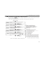
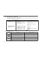
Test Run
The Inverter operates when a frequency (speed) is set.
There are four operating modes for the Varispeed V7:
1. RUN command from the Digital Operator (potentiometer/digital setting)
2. RUN command from the control circuit terminals
3. RUN command from DeviceNet communications
Prior to shipping, the Inverter is set up to receive the RUN command
and frequency reference from the Operator. Below are instructions for
running the Varispeed V7 using the JVOP-147 Digital Operator (without potentiometer). For instructions on operation, refer to page 53.
Operation reference or frequency reference constants can be selected
separately as shown below.
Name
42
Constant
RUN Command Selection
n003
= 0 --- Enables run, stop, and reset from Digital Operator.
= 1 --- Enables run and stop from control circuit terminals.
= 3 --- Enables DeviceNet communications.
Frequency
Reference
Selection
n004
= 0 --- Enables the Digital Operator’s potentiometer setting.
= 1 --- Enables Frequency Reference 1 (constant n024).
= 7 --- Enables a voltage reference (0 to 10 V) at the Digital Operator’s
circuit terminal.
= 8 --- Enables a current reference (4 to 20 mA) at the Digital Operator’s
circuit terminal.
= 9 --- Enables DeviceNet communications.
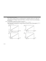
5. Operating the Inverter
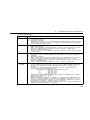
Operation Steps
Operator
Display
1. Turn the potentiometer fully counterclockwise, and then turn the power
ON.
2. F/R will flash.
Select FWD or REV RUN using the
keys.
NOTE
Never select REV when
reverse run is prohibited.
3. Press DSPL to make FREF flash.
Then press RUN.
4. Operate the motor by turning the
potentiometer clockwise. (A frequency reference corresponding to
the potentiometer position will be displayed.)
NOTE
Function
Indicators
Status Indicators
0
FOR
or
REV
0
0 to 1800
(r/min)
Minimum
output
frequency is
45 r/min
If the potentiometer is
switched rapidly, the motor
also accelerates or decelerate rapidly in proportion to the
potentiometer movement.
Pay attention to load status
and switch the potentiometer
at a speed that will not
adversely affect motor movement.
Status indicators
: ON
: Flashing
: OFF
Operation Check Points
•
•
•
•
•
•
Motor rotates smoothly.
Motor rotates in the correct direction.
Motor does not have abnormal vibration or noise.
Acceleration and deceleration are smooth.
Current matching the load flows.
Status indicators and Digital Operator display are correct.
43
Operating the Digital Operator
All functions of the Varispeed V7 are set using the Digital Operator.
Below are descriptions of the display and keypad sections.
JVOP-140 Digital Operator
Data display section
Indicator/display section
Function indicators
Indicators switch to another
function each time
is pressed.
The displayed data can
be changed.
Frequency setting
potentiometer
Used to change
frequency setting.
Press to switch
between
functions.
Press to enter the
constant data.
(Displays the constant Press to increase
constant No./data
data when
value.
selecting a constant no.
for
indicator.)
Press to run
the motor.
Status indicator
(same function as
RUN indicator)
Operator CN2 terminal Press to decrease
constant no./data
value.
Press to stop the motor.
(Press to reset faults.)
(Rear side of the operator)
CN2-3: GND for Operator circuit terminal
CN2-1: Operator circuit terminal
(voltage reference)
CN2-2: Operator circuit terminal
(current reference)
Details of Indicators (Color in parenthesis indicates the color of indicator.)
FREF
Frequency reference
setting/monitoring
(GREEN)
F/R
Operator RUN
command FWD/REV
selection
(GREEN)
44
FOUT
Output frequency
monitoring
(GREEN)
IOUT
Output current
monitoring
(GREEN)
MNTR
Multi-function
monitoring
(GREEN)
LO/RE
LOCAL/REMOTE
Selection
(RED)
PRGM
Constant no./data
(RED)
5. Operating the Inverter
Description of Status Indicators
The following diagram shows the positions of four status indicators
(two Inverter operation status indicators, two DeviceNet communications status indicators). The combinations of these indicators indicate
the status of the Inverter and DeviceNet communications (On, flashing,
and OFF).
RUN
ALARM
Inverter Operation
Status Indicators
DeviceNet
Communications
Status Indicators
Inverter Operation Status Indicators
:ON
RUN
ALARM
:Flashing (long flashing)
(Green)
(Red)
Operation ready
(During stop)
:Flashing
Ramp to
stop
:OFF
Normal
operation
For details on how the status indicators function for Inverter faults, refer
to Chapter 9. Fault Diagnosis. If a fault occurs, the ALARM indicator
will light.
NOTE
The fault can be reset by turning ON the FAULT RESET signal (or by pressing the
key on the Digital Operator)
with the operation signal OFF, or by turning OFF the power
supply. If the operation signal is ON, the fault cannot be reset
using the FAULT RESET signal.
45
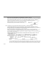
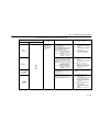
DeviceNet Communications Status Indicators
These indicators show the status of DeviceNet communications.
Name
MS
NS
46
Indication
Operating Status
Remarks
Color
Status
Green
ON
Inverter communications operating
The Inverter is operating normally.
Green
Flashing
Inverter communications initializing
There is an incorrect
baud rate setting or
there is a MAC ID duplication.
Red
ON
Fatal error occurred
A fatal (irrecoverable)
error occurred in the
Inverter.
Red
Flashing
Non-fatal error occurred
A non-fatal (recoverable) error occurred.
---
OFF
Power supply OFF
DeviceNet communications are not online.
Network power is not
being supplied to the
Inverter.
Green
ON
Online communications
established.
DeviceNet communications are operating normally.
Green
Flashing
Online communications
not established.
DeviceNet communications are operating normally, but
communications have
not been established
with the Master.
Red
ON
Communications error
An error occurred that
disables DeviceNet
communications.
• MAC ID duplication
• Bus Off detected
Red
Flashing
Communications timeout
A communications timeout occurred with the
Master.
---
OFF
Offline or Power supply OFF
DeviceNet communications are not online.
Power is not being supplied to the Inverter.
The baud rate settings
do not agree.
5. Operating the Inverter
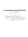
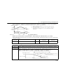
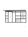
Function Indicator Description
By pressing
on the Digital Operator, each of the function indicators can be selected.
The following flowchart describes each function indicator.
Power ON
Frequency reference setting/monitoring
(r/min)
Sets Varispeed V7 operating speed.
Output frequency monitoring (r/min)
Displays frequency that Varispeed V7 is
currently outputting
Setting disabled.
Output current monitoring (A)
Displays current that Varispeed V7 is
currently outputting
Setting disabled.
Multi-function monitoring
Description of the selected monitor is
displayed.
(Refer to page 49 for details.)
FWD/REV run selection
Sets the motor rotation direction when the RUN
command is given from the Digital Operator.
Setting can be changed using the
or
key.
(forward run)
(reverse run)
If the Varispeed V7
loses power while in
one of these modes,
it will return to the same
mode once power is
restored.
Monitor No.
U-01: Frequency reference (FREF)
U-02: Output frequency (FOUT)
U-03: Output current (IOUT)
U-04: Output voltage reference (Unit: 1V)
U-05: DC voltage (Unit: 1V)
U-06: Input terminal status
U-07: Output terminal status
U-08: Torque monitor
U-09: Fault history
U-10: Software number
U-11: Output power
U-16: PID feedback
U-17: PID input
U-18: PID output
U-60: DeviceNet produced connection path
U-61: DeviceNet consumed connection path
U-62: MAC ID Setting (on Rotary Switches)
U-63: MAC ID Setting (during operation)
U-64: Baud Rate Setting (on Rotary Switch)
U-65: Baud Rate Setting (during operation)
U-66: DeviceNet Connection instance status
U-70: Frequency reference from DeviceNet
Note: The unit used for frequency is determined by the value set for constant
n035. For details, refer to page 196.
47
LOCAL/REMOTE Selection
This function switches the operation; operation
using the digital operator including frequency
setting with potentiometer, operation using the
input terminals, or operation through communications
Setting can be changed using the
or
key.
(Local)
(Remote)
Constant No./data
Sets and changes data for a constant No.
(Refer to page 52.)
Return to
MNTR Multi-function Monitoring
Selecting the Monitor
Press the
key. When
is ON, data
can be displayed by selecting the monitor number.
Example: Monitoring the Output Voltage Reference
or
Select U-04 by
pressing the
or
key.
48
Output voltage reference
is displayed.
5. Operating the Inverter
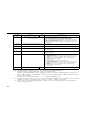
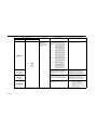
Monitoring
The following items can be monitored using U constants.
Constant
No.
Name
Unit
U-01
Frequency Reference
(FREF)*1*5
r/
min
Frequency reference can be monitored. (Same as
FREF)
U-02
Output Frequency
(FOUT)*1*5
r/
min
Output frequency can be monitored.
(Same as FOUT)
U-03
Output Current (IOUT)*1
A
Output current can be monitored.
(Same as IOUT)
U-04
Output Voltage
V
Output voltage can be monitored.
U-05
DC Voltage
V
Main circuit DC voltage can be monitored.
U-06
Input Terminal Status*2
-
Input terminal status of control circuit terminals can
be monitored.
-
Output terminal status of control circuit terminals can
be monitored.
U-07
Output Terminal
Status*2
Description
U-08
Torque Monitor
%
The amount of output torque can be monitored.
When V/f control mode is selected, “---” is displayed.
U-09
Fault History
(Last 4 Faults)
-
The last four fault history records are displayed.
Software number can be checked.
U-10
Software No.
-
U-11
Output Power*3
kW
Output power can be monitored.
U-16
Feedback*4
%
Input 100(%)/Max. output frequency or equivalent
PID
U-17
PID Input*4
%
±100(%)/± Max. output frequency
U-18
PID Output*4
%
±100(%)/± Max. output frequency
U-60
DeviceNet produced Connection Path (Connection Path During Operation)
70: Basic I/O Instance, Response
71: Extended I/O Instance, Response
150: MEMOBUS I/O Instance, Response
151: V7N Control I/O Instance, Response
152: Acceleration/Deceleration Time Control I/O Instance, Response
155: Extended MEMOBUS I/O Instance, Response
156: General-purpose DI/DO Control I/O Instance,
Response
20: Basic I/O Instance, Command
21: Extended I/O Instance, Command
100: MEMOBUS I/O Instance, Command
101: V7N Control I/O Instance, Command
102: Acceleration/Deceleration Time Control I/O Instance, Command
105: Extended MEMOBUS I/O Instance, Command
106: General-purpose DI/DO Control I/O Instance,
Command
49
Constant
No.
Name
Unit
Description
U-61
DeviceNet consumed Connection Path (Connection Path During Operation)
20: Basic I/O Instance, Command
21: Extended I/O Instance, Command
100: MEMOBUS I/O Instance, Command
101: V7N Control I/O Instance, Command
102: Acceleration/Deceleration Time Control I/O Instance, Command
105: Extended MEMOBUS I/O Instance, Command
106: General-purpose DI/DO Control I/O Instance,
Command
U-62
MAC ID Selection (Setting on
Rotary Switches)
0 to 63
U-63
MAC ID Setting (MAC ID during
Operation)
0 to 63
U-64
Baud Rate Setting (Setting on
Rotary Switch)
0: 125 kbps
1: 250 kbps
2: 500 kbps
U-65
Baud Rate Setting (Baud Rate
during Operation)
125: 125 kbps
250: 250 kbps
500: 500 kbps
U-66
Status of DeviceNet
connection instance
1st digit: Status of explicit instance
0: No instance exists in the network or one is now
being prepared.
1: Waiting to be connected to the master while online.
2: Waiting for the connection ID to be written in.
3: Connection completed
4: Time-out
2nd digit: Status of Polled ID instance
0: No instance exists in the network or one is now
being prepared.
1: Waiting to be connected to the master while online.
2: Waiting for the connection ID to be written in.
3: Connection completed
4: Time-out
U-70
Frequency reference
from DeviceNet
r/
min
The frequency reference from the DeviceNet can be
monitored.
* 1. The status indicator is not turned ON.
* 2. Refer to the next page for input/output terminal status.
* 3. The display range is from −99.9 to 99.99 kW.
When regenerating, the output power will be displayed in units of
0.01 kW when −9.99 kW or less and in units of 0.1 kW when more
than −9.99 kW.
In vector control mode, “---” will be displayed.
* 4. Displayed in units of 0.1% when less than 100% and in units of 1% when
100% or more. The display range is from −999% to 999%.
* 5. The unit is determined by the value set for constant n035. For details,
refer to page 196.
50
5. Operating the Inverter
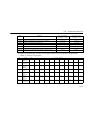
Input/Output Terminal Status
Input terminal status
1: Terminal S1 is closed.
1: Terminal S2 is closed.
1: Terminal S3 is closed. (see note 1.)
1: Terminal S4 is closed. (see note 1.)
1: Terminal S5 is closed. (see note 2.)
1: Terminal S6 is closed. (see note 2.)
1: Terminal S7 is closed. (see note 2.)
Note: 1. “1” is also displayed if command input from DeviceNet communications or the external control terminal is closed.
2. “1” is displayed if command input from DeviceNet communications
is closed. There are no external terminals.
Output terminal status
1: Terminal MA is closed. (see note.)
1: Terminal P1-PC is closed.
1: Terminal P2-PC is closed.
Note: This can only be used from DeviceNet communications. There is no
external output terminal.
51
Fault History Display Method
When U-09 is selected, a four-digit box is displayed. The three digits
from the right show the fault description, and the digit on the left shows
the order of fault (from one to four). Number 1 represents the most
recent fault, and numbers 2, 3, 4 represent the other faults, in ascending
order of fault occurrence.
Example:
4-digit number
: Order of fault (1 to 4)
: Fault description
"---" is displayed if there is no fault.
(Refer to Chapter 9. Fault Diagnosis for details.)
Switching Fault History Records
The fault that is displayed can be changed using the
or
key.
Clearing the Fault History
Set constant n001 to 6 to clear the fault history. The display will return
to n001 after 6 is set.
Note: Initializing the constants (n001=12, 13) also clears the fault history.
Setting and Referencing Constants
The following diagram shows how to select and change constants.
REMOTE/LOCAL
selection
• Setting n003 (RUN command selection)
Constant
No./
data
n003
Operation
reference
selection
Factory setting: 0
Operator reference
Return to
constant No.
display
52
Set to 1
Control circuit
terminal reference
(flashing at changing)
Data set
5. Operating the Inverter
Simple Data Setting
Digital setting (refer to 5. Operating the Inverter) and potentiometer
setting are both possible for simple acceleration/deceleration operation
of the Varispeed V7.
DeviceNet communications are set to enabled at the factory (n004=9).
Simple Operation from the Digital Operator Using Frequency
Reference
Following is an example in which forward and reverse run is performed
with a standard motor with frequency set to 1,800 r/min, acceleration
time set to 15 s, and deceleration time set to 5 s. (Refer to page 127 for
details on parameter settings.)
53
Operation Steps
Operator Display
1. Turn ON the power supply.
0
2. Set constant n004 to 1.
(Enables the potentiometer and
RUN/STOP commands from
the Digital Operator.)
1
3. Set the following constants.
n019: 15.0 (Acceleration Time)
n020: 5.0 (Deceleration Time)
4. Select forward or reverse run
by pressing the
key.
or
Examine the application.
NOTE (Never select REV when
reverse run is prohibited.)
5. Set the reference by pressing
the
6. Press
7. Press
or
key.
Status Indicators
15.0
5.0
(Forward)
Or
(Rever
se)
1800
0
1800
1800
0
.
to stop.
Status indicators
54
Function
Indicators
:ON
:Flashing (long flashing)
:Flashing
:OFF
6. Operating with DeviceNet Communications
6. Operating with DeviceNet
Communications
Varispeed V7 Inverters can be connected to a DeviceNet network to communicate with a DeviceNet master. The DeviceNet master can be used for
various operations, such as sending RUN/STOP commands, monitoring run
status, and setting/referencing of constants.
Specifications
Item
Specifications
DeviceNet
Specifications
Conform to release 2.0.
Device Protocol
AC Drive
DeviceType = 02
Baud Rate
Settings
125, 250, or 500 kbps
Supported
Messages
Group 2 Only server.
UCMM not supported.
Explicit messages or I/O poll messages
I/O Message
Communications
Seven kinds of I/O instances are supported:
1. Basic I/O instances (4 input bytes, 4 output bytes)
2. Extended I/O instances (4 input bytes,
4 output bytes)
3. MEMOBUS I/O instances (5 input bytes,
5 output bytes)
4. V7 standard control I/O instances (8 input
bytes, 8 output bytes)
5. Acceleration/Deceleration time control I/O
instances (8 input bytes, 8 output bytes)
6. Extended MEMOBUS I/O instances
(8 input bytes, 8 output bytes)
7. General-purpose DI/DO control I/O
instances (8 input bytes, 8 output bytes)
55
Item
Specifications
Explicit Message
Communications
Up to 32 bytes of data can be transferred in
conformance with the DeviceNet AC/DC
drive profile.
Communications
Power Supply
11 to 25 VDC (20 mA max.)
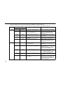
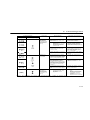
Component Names and Settings
Rotary Switches
The rotary switches are used to set the DeviceNet baud rate and MAC
ID (node address). Always turn OFF the Inverter’s input power supply
before changing the rotary switch settings. The settings will be enabled
the next time the power is turned ON.
RATE
S3
S1
1 2 34
5
0
9 8 76
2
1 34
5
0
9 8 76
1 2 34
5
0
9 8 76
Baud rate
setting
S4
MSB
LSB
ADDRESS
MAC ID Setting MAC ID Setting
10 s digit (MSB) 1 s digit (LSB)
Baud Rate Setting Switch (S1)
Setting
0
1
2
3 to 9
Baud Rate
125 kbps
250 kbps
500 kbps
Use setting in
constant n152.
MAC ID Setting Switches (S3 and S4)
The Inverter’s MAC ID is set on the MSB (S3) and LSB (S4) rotary
switches.
MAC ID = (MSB setting × 10) + (LSB setting)
The MAC ID setting range is 0 to 63. If a value between 64 and 99 is
set, the MAC ID setting in constant n150 will be used.
56
6. Operating with DeviceNet Communications
Description of the DeviceNet Functions
DeviceNet-compatible Inverters support the AC Drive Profile defined
in DeviceNet specifications. No special settings are needed to operate,
adjust, and monitor the Inverters from any DeviceNet master.
DeviceNet-compatible Inverters operate as Group 2 Only servers
(DeviceNet slaves) in the DeviceNet network. Two kinds of communications are possible with the master: I/O messages and explicit messages.
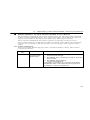
Initial Settings
Always set the following Inverter constants before using DeviceNet
communications.
Constant
No.
n003
Name
RUN
Command
Selection
Description
0: Enables the Digital Operator’s RUN
and STOP Keys.
1: Enables the run/stop control circuit
terminals.
3: Enables DeviceNet
communications.
Set this constant to 3 when sending
RUN/STOP commands through DeviceNet communications.
57
Constant
No.
58
Name
Description
n004
Frequency
Reference
Selection
0: Enables the Digital Operator’s
potentiometer setting.
1: Enables Frequency Reference 1
(constant n024).
7: Enables a voltage reference (0 to
10 V) at the Digital Operator’s circuit terminal.
8: Enables a current reference (4 to
20 mA) at the Digital Operator’s
circuit terminal.
9: Enables DeviceNet
communications.
Set this constant to 9 when setting the
frequency through DeviceNet communications.
n035
Selecting
Setting/Display Units of
Frequency
Reference
Always set the number of motor poles
(2 to 39).
In DeviceNet standards, the motor
speed is expressed in units of r/min.
The Inverter uses this constant setting
to convert the frequency to r/min.
6. Operating with DeviceNet Communications
I/O Message Communications
The DeviceNet-compatible Inverters use poll command/response messages for I/O message communications. Select one of the seven supported I/O instances and transfer I/O data with the master. I/O messages
are always transferred between the Inverter and master at the fixed communications period whether or not there have been changes to the I/O
data.
Basic I/O Instances
This is a standard I/O instance type defined in DeviceNet’s AC Drive
Profile. Four bytes are used for input data and four bytes are used for
output data.
• Input (Master → Inverter) Instance 20 (14 Hex)
Byte
Bit 7
Bit 6
Bit 5
Bit 4
Bit 3
Bit 2
Bit 1
Bit 0
0
---
---
---
---
---
Fault
Reset
---
Run
Fwd
1
---
---
---
---
---
---
---
---
2
Speed Reference (Low Byte)
3
Speed Reference (High Byte)
Data
Name
Contents
Byte 0,
bit 0
Run Fwd
Runs the Inverter forward.
0: Stop.
1: Run forward.
Byte 0,
bit 2
Fault Reset Resets the Inverter from fault status.
0: --1: Reset fault.
59
Data
Name
Bytes
2 and 3
Speed
Reference
*3
Contents
Sets the Inverter’s speed reference.
Speed reference data:
Frequency reference (r/min) × 2SS
(SS: Speed scale*1)
Setting range: 0 to FFFF Hex*2
For example, when setting a reference
of 1,800 r/min with a speed scale of 0:
Speed reference data = 1,800 × 20 =
1,800 = 0708 Hex
* 1. The speed scale can be set with AC/DC Drive object attribute 16 through
explicit message communications.
* 2. The speed reference setting cannot exceed the Inverter’s Maximum Output Frequency Setting in constant n011.
* 3. When using the speed reference, always set the Number of Motor Poles (2
to 39) in Inverter constant n035 (Selecting Setting/Display Units of Frequency Reference).
• Output (Inverter → Master) Instance 70 (46 Hex)
Byte
Bit 7
Bit 6
Bit 5
Bit 4
Bit 3
Bit 2
Bit 1
Bit 0
0
---
---
---
---
---
Running 1
(Fwd)
---
Faulted
---
---
---
---
---
---
---
---
1
2
Speed Actual (Low Byte)
3
Speed Actual (High Byte)
Data
Byte 0,
bit 0
60
Name
Faulted
Contents
Indicates that the Inverter detected a
fault.
0: Normal
1: Fault detected.
6. Operating with DeviceNet Communications
Data
Name
Contents
Byte 0,
bit 2
Running 1
(Fwd)
Indicates the Inverter’s operating status.
0: Stopped, operating in reverse, or
applying DC injection braking
(Reverse RUN command ON).
1: Operating forward or applying DC
injection braking (Reverse RUN command OFF).
Bytes
2 and 3
Speed
Actual
Indicates the Inverter’s speed.
Monitored speed data:
Monitored frequency (r/min) × 2SS
(SS: Speed scale*1)
For example, when the monitored speed
data is 03E8 Hex and the speed scale is
0:
Monitored frequency = 03E8 Hex/ 20 =
1,000/ 20 = 1,000 r/min.
* 1. The speed scale can be set with AC/DC Drive object attribute 16 through
explicit message communications.
* 2. When using the Speed Actual monitor, always set the Number of Motor
Poles (2 to 39) in Inverter constant n035 (Selecting Setting/Display Units
of Frequency Reference).
Extended I/O Instance (Factory Setting)
This is a standard I/O instance type defined in DeviceNet’s AC Drive
Profile and it is the initial factory setting for I/O instances. Four bytes
are used for input data and four bytes are used for output data.
• Input (Master → Inverter) Instance 21 (15 Hex)
Byte
Bit 7
Bit 6
Bit 5
Bit 4
Bit 3
Bit 2
Bit 1
Bit 0
0
---
Net
Ref
Net
Ctrl
---
---
Fault
Reset
Run
Rev
Run
Fwd
---
---
---
---
---
---
---
---
1
2
Speed Reference (Low Byte)
3
Speed Reference (High Byte)
61
Data
Name
Contents
Byte 0,
bit 0
Run Fwd
Runs the Inverter forward.
0: Stop.
1: Run forward.
Byte 0,
bit 1
Run Rev
Runs the Inverter in reverse.
0: Stop.
1: Run in reverse.
Byte 0,
bit 2
Fault Reset Resets the Inverter from fault status.
0: --1: Reset fault.
Byte 0,
bit 5
NetCtrl
Sets the RUN command right.
0: Use the RUN Command Input Method
set in constant n003 (RUN Command
Selection).
1: Enables the RUN command from
DeviceNet (byte 0, bits 0 and 1).
Byte 0,
bit 6
NetRef
Sets the Frequency Reference right.
0: Use the Frequency Reference Input
Method set in constant n004 (Frequency Reference Selection).
1: Enables the Frequency Reference
from DeviceNet (bytes 2 and 3).
Bytes
2 and 3
Speed
Reference
Sets the Inverter’s speed reference.
The speed reference is exactly the same
as it is in a Basic I/O Instances.
• Output (Inverter → Master) Instance 71 (47 Hex)
Byte
Bit 7
Bit 6
Bit 5
Bit 4
Bit 3
Bit 2
Bit 1
Bit 0
0
At Reference
Ref
From
Net
Ctrl
From
Net
Ready
Running 2
(Rev)
Running 1
(Fwd)
Warning
Faulted
---
---
---
---
---
---
---
---
1
2
62
Speed Actual (Low Byte)
6. Operating with DeviceNet Communications
Byte
3
Bit 7
Bit 6
Bit 5
Bit 4
Bit 3
Bit 2
Bit 1
Bit 0
Speed Actual (High Byte)
Data
Name
Contents
Byte 0,
bit 0
Faulted
Indicates that the Inverter detected a
fault.
0: Normal
1: Fault detected.
Byte 0,
bit 1
Warning
Indicates that the Inverter detected a
warning.
0: Normal
1: Warning detected.
Byte 0,
bit 2
Running 1
(Fwd)
Indicates the Inverter’s operating status.
0: Stopped, operating in reverse, or
applying DC injection braking
(Reverse RUN command ON).
1: Operating forward or applying DC
injection braking (Reverse RUN command OFF).
Byte 0,
bit 3
Running 2
(Rev)
Indicates the Inverter’s operating status.
0: Stopped, operating forward, or applying DC injection braking (Reverse
RUN command OFF).
1: Operating in reverse or applying DC
injection braking (Reverse RUN command ON).
Byte 0,
bit 4
Ready
Indicates the Inverter’s preparation status.
0: Fault detected or initializing.
1: Preparations for operation completed.
63
Data
Name
Contents
Byte 0,
bit 5
Ctrl From
Net
Indicates which RUN command input
has been selected in the Inverter.
0: A RUN command input other than
DeviceNet is enabled.
1: The RUN command input from
DeviceNet is enabled.
Byte 0,
bit 6
Ref From
Net
Indicates which Frequency Reference
input has been selected in the Inverter.
0: A Frequency Reference input other
than DeviceNet is enabled.
1: The Frequency Reference input from
DeviceNet is enabled.
Byte 0,
bit 7
At Reference
Indicates that the Inverter’s frequency
match was detected.
0: Stopped, accelerating, or decelerating.
1: Frequency matches.
Bytes
2 and 3
Speed
Actual
Indicates the Inverter’s speed.
The speed data is exactly the same as it
is in the Basic I/O Instances.
MEMOBUS I/O Instances
All of the Inverter’s constants can be referenced and set with a
MEMOBUS I/O instance.
MEMOBUS I/O instances can be used with Yaskawa Inverters only.
They cannot be used with other companies’ DeviceNet-compatible
Inverters.
Five bytes are used for input data and five bytes are used for output
data.
Always execute the ENTER command when changing constants. See
ENTER Command (Write-only Register) on page 126 for details.
64
6. Operating with DeviceNet Communications
• Input (Master → Inverter) Instance 100 (64 Hex)
Byte
Bit 7
Bit 6
Bit 5
Bit 4
0
Function Code
1
Register Number (High Byte)
2
Register Number (Low Byte)
3
Register Data (High Byte)
4
Register Data (Low Byte)
Data
Name
Bit 3
Bit 2
Bit 1
Bit 0
Contents
Byte 0
Function
Code
Set the MEMOBUS (command message) function code.
03 Hex: Read
10 Hex: Write
00 Hex: Do not execute.
Bytes
1 and 2
Register
Number
Set the Inverter’s MEMOBUS register
number.
Bytes
3 and 4
Register
Data
Set the write data when executing a MEMOBUS WRITE command.
• Output (Inverter → Master) Instance 150 (96 Hex)
Byte
Bit 7
Bit 6
Bit 5
Bit 4
0
Function Code
1
Register Number (High Byte)
2
Register Number (Low Byte)
3
Register Data (High Byte)
4
Register Data (Low Byte)
Bit 3
Bit 2
Bit 1
Bit 0
65
Data
Name
Contents
Byte 0
Function
Code
Indicates the MEMOBUS (response
message) function code.
00 Hex: Do not execute.
03 Hex: Normal read
10 Hex: Normal write
83 Hex: Read error
90 Hex: Write error
Bytes
1 and 2
Register
Number
Indicates the MEMOBUS register number in the executed process. These
bytes will contain the MEMOBUS error
code if a read or write error occurred.
Bytes
3 and 4
Register
Data
Indicates the read data when executing
a MEMOBUS READ command.
Shows “00, 00” if an attempt is made to
write the same data to the same address; the WRITE command will not be
executed.
V7 Standard Control I/O Instances
V7 Standard control I/O instances are for DeviceNet-compatible Inverters only. All of the Inverter’s I/O functions can be used in addition to
the functions supported by the Extended I/O Instances.
V7 Standard control I/O instances can be used with Yaskawa Inverters
only. They cannot be used with other companies’ DeviceNet-compatible Inverters.
Eight bytes are used for input data and eight bytes are used for output
data.
• Input (Master → Inverter) Instance 101 (65 Hex)
Byte
66
Bit 7
Bit 6
Bit 5
Bit 4
Bit 3
Bit 2
Bit 1
Bit 0
0
---
Terminal S7*
Terminal S6*
Terminal S5*
Terminal S4
Terminal S3
Run
Rev
Run
Fwd
1
Terminal P2
Terminal P1
Terminal
MA*
---
---
---
Fault
Reset
External
Fault
2
Speed Reference (Low Byte)
6. Operating with DeviceNet Communications
Byte
Bit 7
Bit 6
Bit 5
Bit 4
3
Speed Reference (High Byte)
4
---
5
---
6
---
7
---
Data
Name
Bit 3
Bit 2
Bit 1
Bit 0
Contents
Byte 0,
bit 0
Run Fwd
Runs the Inverter forward.
0: Stop.
1: Run forward.
Byte 0,
bit 1
Run Rev
Runs the Inverter in reverse.
0: Stop.
1: Run in reverse.
Byte 0,
bit 2
Terminal
S3
Inputs the function set for the Inverter’s
multi-function input terminal S3. Set the
function of multi-function input terminal
S3 with Inverter constant n052.
0: Terminal S3 function OFF
1: Terminal S3 function ON
Byte 0,
bit 3
Terminal
S4
Inputs the function set for the Inverter’s
multi-function input terminal S4. Set the
function of multi-function input terminal
S4 with Inverter constant n053.
0: Terminal S4 function OFF
1: Terminal S4 function ON
Byte 0,
bit 4
Terminal
S5*
Inputs the function set for Inverter constant n054 (Multi-function Input Selection 5.)
0: Terminal S5 function OFF
1: Terminal S5 function ON
67
Data
Name
Contents
Byte 0,
bit 5
Terminal
S6*
Inputs the function set for Inverter constant n055 (Multi-function Input Selection 6.)
0: Terminal S6 function OFF
1: Terminal S6 function ON
Byte 0,
bit 6
Terminal
S7*
Inputs the function set for Inverter constant n056 (Multi-function Input Selection 7.)
0: Terminal S7 function OFF
1: Terminal S7 function ON
* These terminals can be used only from DeviceNet communications. There
are no corresponding external input terminals or output terminals.
Data
68
Name
Contents
Byte 1,
bit 0
External
Fault
External fault (EF0) input from communications.
0: --1: External fault (EF0)
Byte 1,
bit 1
Fault Reset Resets the Inverter from fault status.
0: --1: Reset fault.
Byte 1,
bit 5
Terminal
MA*
Operates the Inverter’s multi-function
output terminal MA. This function is enabled only when Inverter constant n057
is set to 18.
0: Terminal MA OFF
1: Terminal MA ON
Byte 1,
bit 6
Terminal
P1
Operates the Inverter’s multi-function
output terminal P1. This function is enabled only when Inverter constant n058
is set to 18.
0: Terminal P1 OFF
1: Terminal P1 ON
6. Operating with DeviceNet Communications
Data
Name
Contents
Byte 1,
bit 7
Terminal
P2
Operates the Inverter’s multi-function
output terminal P2. This function is enabled only when Inverter constant n059
is set to 18.
0: Terminal P2 OFF
1: Terminal P2 ON
Bytes
2 and 3
Speed
Reference
Sets the Inverter’s speed reference.
The units depend on the setting in Inverter constant n035. The units are not affected by the speed scale (SS) setting.
* Terminal MA can be used only from DeviceNet communications. There is
no corresponding external output terminal.
• Output (Inverter → Master) Instance 151 (97 Hex)
Byte
Bit 7
Bit 6
Bit 5
Bit 4
Bit 3
Bit 2
Bit 1
Bit 0
0
Faulted
Warning
Ready
At Reference
Reset
Rev
Running
ZSP
Running
1
---
---
Terminal P2
Terminal P1
Terminal
MA*
Local/
Remote
UV
OPE
2
Speed Actual (Low Byte)
3
Speed Actual (High Byte)
4
---
5
---
6
Output Current (Low Byte)
7
Output Current (High Byte)
69
Data
70
Name
Contents
Byte 0,
bit 0
Running
Indicates the Inverter’s operating status.
0: Stopped.
1: Operating forward, operating in
reverse, or applying DC injection
braking.
Byte 0,
bit 1
ZSP
Indicates the Inverter’s operating status.
0: Operating forward or in reverse.
1: Stopped or applying DC injection
braking.
Byte 0,
bit 2
Rev Running
Indicates the Inverter’s operating status.
0: Operating forward, stopped (Reverse
RUN command OFF), or applying DC
injection braking (Reverse RUN command OFF).
1: Operating in reverse, stopped
(Reverse RUN command ON), or
applying DC injection braking
(Reverse RUN command ON).
Byte 0,
bit 3
Reset
Indicates the input status of the
Inverter’s RESET signal.
0: --1: RESET signal being input.
Byte 0,
bit 4
At Reference
Indicates that the Inverter’s frequency
match was detected.
0: Stopped, accelerating, or decelerating.
1: Frequency matches.
Byte 0,
bit 5
Ready
Indicates the Inverter’s preparation status.
0: Fault detected or initializing.
1: Preparations for operation completed.
6. Operating with DeviceNet Communications
Data
Name
Contents
Byte 0,
bit 6
Warning
Indicates that the Inverter detected a
warning.
0: Normal
1: Warning detected.
Byte 0,
bit 7
Faulted
Indicates that the Inverter detected a
fault.
0: Normal
1: Fault detected.
Byte 1,
bit 0
OPE
Indicates that the Inverter detected a
MEMOBUS constant setting error
(OPE).
0: Normal
1: OPE (OP1 to OP5) detected.
Byte 1,
bit 1
UV
Indicates that the Inverter detected an
undervoltage error.
0: Normal
1: UV detected.
Byte 1,
bit 2
Local/Remote
Indicates which RUN command input
has been selected in the Inverter.
0: A RUN command input other than
DeviceNet is enabled.
1: The RUN command input from
DeviceNet is enabled.
Byte 1,
bit 3
Terminal
MA*
Indicates the output status of Inverter
multi-function output terminal MA.
0: Terminal MA OFF
1: Terminal MA ON
Byte 1,
bit 4
Terminal
P1
Indicates the output status of Inverter
multi-function output terminal P1.
0: Terminal P1 OFF
1: Terminal P1 ON
71
Data
Name
Contents
Byte 1,
bit 5
Terminal
P2
Indicates the output status of Inverter
multi-function output terminal P2.
0: Terminal P2 OFF
1: Terminal P2 ON
Bytes
2 and 3
Speed Actual
Indicates the Inverter’s speed.
The units depend on the setting in Inverter constant n035. The units are not affected by the speed scale (SS) setting.
Bytes
6 and 7
Output
Current
Indicates the Inverter’s output current.
The units are fixed at 0.1 A. The units
are not affected by the current scale
(CS) setting.
* Terminal MA can be used only from DeviceNet communications. There is
no corresponding external output terminal.
Acceleration/Deceleration Time Control I/O Instances
Acceleration/Deceleration Time Control I/O Instances are for
DeviceNet-compatible Inverters only. They support the functions of the
V7 standard control I/O instances and also allow the acceleration/deceleration time to be set and the motor speed (estimated value) to be monitored. Eight bytes are used for input data and eight bytes are used for
output data.
72
6. Operating with DeviceNet Communications
• Input (Master → Inverter) Instance 102 (66 Hex)
Byte
Bit 7
Bit 6
Bit 5
Bit 4
Bit 3
Bit 2
Bit 1
Bit 0
0
---
Terminal S7*
Terminal S6*
Terminal S5*
Terminal S4
Terminal S3
Run
Rev
Run
Fwd
1
Terminal P2
Terminal P1
Terminal
MA*
---
---
---
Fault
Reset
External
Fault
2
Speed Reference (Low Byte)
3
Speed Reference (High Byte)
4
Acceleration Time 1 (Low Byte)
5
Acceleration Time 1 (High Byte)
6
Deceleration Time 1 (Low Byte)
7
Deceleration Time 1 (High Byte)
Data
Name
Contents
Byte 0,
bit 0
Run Fwd
Runs the Inverter forward.
0: Stop.
1: Run forward.
Byte 0,
bit 1
Run Rev
Runs the Inverter in reverse.
0: Stop.
1: Run in reverse.
Byte 0,
bit 2
Terminal
S3
Inputs the function set for the Inverter’s
multi-function input terminal S3. Set the
function of multi-function input terminal
S3 with Inverter constant n052.
0: Terminal S3 function OFF
1: Terminal S3 function ON
73
Data
74
Name
Contents
Byte 0,
bit 3
Terminal
S4
Inputs the function set for the Inverter’s
multi-function input terminal S4. Set the
function of multi-function input terminal
S4 with Inverter constant n053.
0: Terminal S4 function OFF
1: Terminal S4 function ON
Byte 0,
bit 4
Terminal
S5*
Inputs the function set for Inverter constant n054 (Multi-function Input Selection 5.)
0: Terminal S5 function OFF
1: Terminal S5 function ON
Byte 0,
bit 5
Terminal
S6*
Inputs the function set for Inverter constant n055 (Multi-function Input Selection 6.)
0: Terminal S6 function OFF
1: Terminal S6 function ON
Byte 0,
bit 6
Terminal
S7*
Inputs the function set for Inverter constant n056 (Multi-function Input Selection 7.)
0: Terminal S7 function OFF
1: Terminal S7 function ON
Byte 1,
bit 0
External
Fault
External fault (EF0) input from communications.
0: --1: External fault (EF0)
Byte 1,
bit 1
Fault Reset Resets the Inverter from fault status.
0: --1: Reset fault.
6. Operating with DeviceNet Communications
Data
Name
Contents
Byte 1,
bit 5
Terminal
MA*
Operates the Inverter’s multi-function
output terminal MA. This function is enabled only when Inverter constant n057
is set to 18.
0: Terminal MA OFF
1: Terminal MA ON
Byte 1,
bit 6
Terminal
P1
Operates the Inverter’s multi-function
output terminal P1. This function is enabled only when Inverter constant n058
is set to 18.
0: Terminal P1 OFF
1: Terminal P1 ON
Byte 1,
bit 7
Terminal
P2
Operates the Inverter’s multi-function
output terminal P2. This function is enabled only when Inverter constant n059
is set to 18.
0: Terminal P2 OFF
1: Terminal P2 ON
Bytes
2 and 3
Frequency
Reference
Sets the Inverter’s speed reference.
This setting is the same as the speed
reference in the V7 standard control I/O
instance. The units depend on the setting in Inverter constant n035.
Bytes
4 and 5
Acceleration Time 1
Sets the Inverter’s acceleration time.
The units depend on the setting in
Inverter constant n018. (The factory setting is for units of 0.1 s.) The value set
here is recorded in EEPROM. The units
are not affected by the time scale (TS)
setting.
75
Data
Name
Contents
Bytes
6 and 7
Deceleration Time 1
Sets the Inverter’s deceleration time.
The units depend on the setting in
Inverter constant n018. (The factory setting is for units of 0.1 s.) The value set
here is recorded in EEPROM. The units
are not affected by the time scale (TS)
setting.
* Terminal MA can be used only from DeviceNet communications. There is
no corresponding external output terminal.
• Output (Inverter → Master) Instance 152 (98 Hex)
Byte
Bit 7
Bit 6
Bit 5
Bit 4
Bit 3
Bit 2
Bit 1
Bit 0
0
Faulted
Warning
Ready
At Reference
Reset
Rev
Running
ZSP
Running
1
---
---
Terminal P2
Terminal P1
Terminal
MA*
Local/
Remote
UV
OPE
2
Speed Actual (Low Byte)
3
Speed Actual (High Byte)
4
Speed Reference (Low Byte)
5
Speed Reference (High Byte)
6
Output Current (Low Byte)
7
Output Current (High Byte)
Data
Byte 0,
bit 0
76
Name
Running
Contents
Indicates the Inverter’s operating status.
0: Stopped.
1: Operating forward, operating in
reverse, or applying DC injection
braking.
6. Operating with DeviceNet Communications
Data
Name
Contents
Byte 0,
bit 1
ZSP
Indicates the Inverter’s operating status.
0: Operating forward or in reverse.
1: Stopped or applying DC injection
braking.
Byte 0,
bit 2
Rev Running
Indicates the Inverter’s operating status.
0: Operating forward, stopped (Reverse
RUN command OFF), or applying DC
injection braking (Reverse RUN command OFF).
1: Operating in reverse, stopped
(Reverse RUN command ON), or
applying DC injection braking
(Reverse RUN command ON).
Byte 0,
bit 3
Reset
Indicates the input status of the
Inverter’s RESET signal.
0: --1: RESET signal being input.
Byte 0,
bit 4
At Reference
Indicates that the Inverter’s frequency
match was detected.
0: Stopped, accelerating, or decelerating.
1: Frequency matches.
Byte 0,
bit 5
Ready
Indicates the Inverter’s preparation status.
0: Fault detected or initializing.
1: Preparations for operation completed.
Byte 0,
bit 6
Warning
Indicates that the Inverter detected a
warning.
0: Normal
1: Warning detected.
77
Data
78
Name
Contents
Byte 0,
bit 7
Faulted
Indicates that the Inverter detected a
fault.
0: Normal
1: Fault detected.
Byte 1,
bit 0
OPE
Indicates that the Inverter detected a
MEMOBUS constant setting error
(OPE).
0: Normal
1: OPE (OP1 to OP5) detected.
Byte 1,
bit 1
UV
Indicates that the Inverter detected an
undervoltage error.
0: Normal
1: UV detected.
Byte 1,
bit 2
Local/Remote
Indicates which RUN command input
has been selected in the Inverter.
0: A RUN command input other than
DeviceNet is enabled.
1: The RUN command input from
DeviceNet is enabled.
Byte 1,
bit 3
Terminal
MA*
Indicates the output status of Inverter
multi-function output terminal MA.
0: Terminal MA OFF
1: Terminal MA ON
Byte 1,
bit 4
Terminal
P1
Indicates the output status of Inverter
multi-function output terminal P1.
0: Terminal P1 OFF
1: Terminal P1 ON
Byte 1,
bit 5
Terminal
P2
Indicates the output status of Inverter
multi-function output terminal P2.
0: Terminal P2 OFF
1: Terminal P2 ON
6. Operating with DeviceNet Communications
Data
Name
Contents
Bytes
2 and 3
Speed Actual
Indicates the Inverter’s speed.
The units depend on the setting in
Inverter constant n035. The units are not
affected by the speed scale (SS) setting.
Bytes
4 and 5
Speed
Reference
Indicates the Inverter’s speed reference.
The units depend on the setting in
Inverter constant n035. The units are not
affected by the speed scale (SS) setting.
Bytes
6 and 7
Output
Current
Indicates the Inverter’s output current.
The units are fixed at 0.1 A. The units
are not affected by the current scale
(CS) setting.
* These terminals can be used only from DeviceNet communications. There
are no corresponding external input or output terminals.
Extended MEMOBUS I/O Instances
Extended MEMOBUS I/O Instances are for DeviceNet-compatible
Inverters only.
Extended MEMOBUS I/O Instances can be used with Yaskawa Inverters only. They cannot be used with other companies’ DeviceNet-compatible Inverters.
Eight bytes are used for input data and eight bytes are used for output
data.
Always execute the ENTER command when changing constants. See
ENTER Command (Write-only Register) on page 126 for details.
• Input (Master → Inverter) Instance 105 (69 Hex)
Byte
Bit 7
Bit 6
Bit 5
Bit 4
Bit 3
Bit 2
Bit 1
Bit 0
0
---
Terminal S7*
Terminal S6*
Terminal S5*
Terminal S4
Terminal S3
Run
Rev
Run
Fwd
1
Terminal P2
Terminal P1
Terminal
MA*
---
Fnc.
Code 2
Fnc.
Code 1
Fault
Reset
External
Fault
2
Speed Reference (Low Byte)
3
Speed Reference (High Byte)
79
Byte
Bit 7
Bit 5
Bit 4
4
Register Number (Low Byte)
5
Register Number (High Byte)
6
Register Data (Low Byte)
7
Register Data (High Byte)
Data
80
Bit 6
Name
Bit 3
Bit 2
Bit 1
Bit 0
Contents
Byte 0,
bit 0
Run Fwd
Runs the Inverter forward.
0: Stop.
1: Run forward.
Byte 0,
bit 1
Run Rev
Runs the Inverter in reverse.
0: Stop.
1: Run in reverse.
Byte 0,
bit 2
Terminal
S3
Inputs the function set for the Inverter’s
multi-function input terminal S3. Set the
function of multi-function input terminal
S3 with Inverter constant n052.
0: Terminal S3 function OFF
1: Terminal S3 function ON
Byte 0,
bit 3
Terminal
S4
Inputs the function set for the Inverter’s
multi-function input terminal S4. Set the
function of multi-function input terminal
S4 with Inverter constant n053.
0: Terminal S4 function OFF
1: Terminal S4 function ON
Byte 0,
bit 4
Terminal
S5*
Inputs the function set for Inverter constant n054 (Multi-function Input Selection 5.)
0: Terminal S5 function OFF
1: Terminal S5 function ON
6. Operating with DeviceNet Communications
Data
Name
Contents
Byte 0,
bit 5
Terminal
S6*
Inputs the function set for Inverter constant n055 (Multi-function Input Selection 6.)
0: Terminal S6 function OFF
1: Terminal S6 function ON
Byte 0,
bit 6
Terminal
S7*
Inputs the function set for Inverter constant n056 (Multi-function Input Selection 7.)
0: Terminal S7 function OFF
1: Terminal S7 function ON
* These terminals can be used only from DeviceNet communications. There
are no corresponding external input terminals or output terminals.
Data
Name
Contents
Byte 1,
bit 0
External
Fault
External fault (EF0) input from communications.
0: --1: External fault (EF0)
Byte 1,
bit 1
Fault Reset Resets the Inverter from fault status.
0: --1: Reset fault.
Byte 1,
bit 2
Fnc. Code
1
Byte 1,
bit 3
Fnc. Code
2
Byte 1,
bit 5
Terminal
MA*
See the table MEMOBUS Function
Codes on page 82 for details.
Operates the Inverter’s multi-function
output terminal MA. This function is enabled only when Inverter constant n057
is set to 18.
0: Terminal MA OFF
1: Terminal MA ON
81
Data
Name
Contents
Byte 1,
bit 6
Terminal
P1
Operates the Inverter’s multi-function
output terminal P1. This function is enabled only when Inverter constant n058
is set to 18.
0: Terminal P1 OFF
1: Terminal P1 ON
Byte 1,
bit 7
Terminal
P2
Operates the Inverter’s multi-function
output terminal P2. This function is enabled only when Inverter constant n059
is set to 18.
0: Terminal P2 OFF
1: Terminal P2 ON
Bytes
2 and 3
Speed
Reference
Sets the Inverter’s speed reference.
The units depend on the setting in Inverter constant n035. The units are not affected by the speed scale (SS) setting.
Bytes
4 and 5
Register
Number
Set the Inverter’s MEMOBUS register
number.
Bytes
6 and 7
Register
Data
Set the write data when executing a MEMOBUS WRITE command.
* Terminal MA can be used only from DeviceNet communications. There is
no corresponding external output terminal.
MEMOBUS Function Codes
82
Status of Function Code 1
(Byte 1, bit 1)
Status of Function Code 2
(Byte 1, bit 2)
Function
Fnc. Code 1 = 0
Fnc. Code 2 = 0
Nothing will be executed.
Fnc. Code 1 = 0
Fnc. Code 2 = 1
The data will be read from
the register specified in
bytes 4 and 5.
6. Operating with DeviceNet Communications
Status of Function Code 1
(Byte 1, bit 1)
Status of Function Code 2
(Byte 1, bit 2)
Function
Fnc. Code 1 = 1
Fnc. Code 2 = 0
The data specified in
bytes 6 and 7 will be written to the register specified in bytes 4 and 5.
Fnc. Code 1 = 1
Fnc. Code 2 = 1
Nothing will be executed.
• Output (Inverter → Master) Instance 155 (9B Hex)
Byte
Bit 7
Bit 6
Bit 5
Bit 4
Bit 3
Bit 2
Bit 1
Bit 0
0
Faulted
Warning
Ready
At Reference
Reset
Rev
Running
ZSP
Running
1
Terminal P2
Terminal P1
Terminal
MA*
Local/
Remote
Fnc.
Code 2
Fnc.
Code 1
UV
OPE
2
Speed Actual (Low Byte)
3
Speed Actual (High Byte)
4
Register Number (Low Byte)
5
Register Number (High Byte)
6
Register Data (Low Byte)
7
Register Data (High Byte)
Data
Byte 0,
bit 0
Name
Running
Contents
Indicates the Inverter’s operating status.
0: Stopped.
1: Operating forward, operating in
reverse, or applying DC injection
braking.
83
Data
84
Name
Contents
Byte 0,
bit 1
ZSP
Indicates the Inverter’s operating status.
0: Operating forward or in reverse.
1: Stopped or applying DC injection
braking.
Byte 0,
bit 2
Rev Running
Indicates the Inverter’s operating status.
0: Operating forward, stopped (Reverse
RUN command OFF), or applying DC
injection braking (Reverse RUN command OFF).
1: Operating in reverse, stopped
(Reverse RUN command ON), or
applying DC injection braking
(Reverse RUN command ON).
Byte 0,
bit 3
Reset
Indicates the input status of the
Inverter’s RESET signal.
0: --1: RESET signal being input.
Byte 0,
bit 4
At Reference
Indicates that the Inverter’s frequency
match was detected.
0: Stopped, accelerating, or decelerating.
1: Frequency matches.
Byte 0,
bit 5
Ready
Indicates the Inverter’s preparation status.
0: Fault detected or initializing.
1: Preparations for operation completed.
Byte 0,
bit 6
Warning
Indicates that the Inverter detected a
warning.
0: Normal
1: Warning detected.
6. Operating with DeviceNet Communications
Data
Name
Contents
Byte 0,
bit 7
Faulted
Indicates that the Inverter detected a
fault.
0: Normal
1: Fault detected.
Byte 1,
bit 0
OPE
Indicates that the Inverter detected a
MEMOBUS constant setting error
(OPE).
0: Normal
1: OPE (OP1 to OP5) detected.
Byte 1,
bit 1
UV
Indicates that the Inverter detected an
undervoltage error.
0: Normal
1: UV detected.
Byte 1,
bit 2
Fnc. State
1
See the table MEMOBUS Function Status on page 87 for details.
Byte 1,
bit 3
Fnc. State
2
Byte 1,
bit 4
Local/Remote
Indicates which RUN command input
has been selected in the Inverter.
0: A RUN command input other than
DeviceNet is enabled.
1: The RUN command input from
DeviceNet is enabled.
Byte 1,
bit 5
Terminal
MA*
Indicates the output status of Inverter
multi-function output terminal MA.
0: Terminal MA OFF
1: Terminal MA ON
Byte 1,
bit 6
Terminal
P1
Indicates the output status of Inverter
multi-function output terminal P1.
0: Terminal P1 OFF
1: Terminal P1 ON
85
Data
Name
Contents
Byte 1,
bit 7
Terminal
P2
Indicates the output status of Inverter
multi-function output terminal P2.
0: Terminal P2 OFF
1: Terminal P2 ON
Bytes
2 and 3
Speed Actual
Indicates the Inverter’s speed.
The units depend on the setting in Inverter constant n035. The units are not affected by the speed scale (SS) setting.
Bytes
4 and 5
Register
Number
Indicates the MEMOBUS register number in the executed process. These
bytes will contain the MEMOBUS error
code if a read or write error occurred.
Bytes
6 and 7
Register
Data
Indicates the read data when executing
a MEMOBUS READ command.
* Terminal MA can be used only from DeviceNet communications. There is
no corresponding external output terminal.
86
6. Operating with DeviceNet Communications
MEMOBUS Function Status
Status of Function State 1
(Byte 1, bit 1)
Status of Function State 2
(Byte 1, bit 2)
Operational Status
Fnc. State 1 = 0
Fnc. State 2 = 0
Not executed yet.
Fnc. State 1 = 0
Fnc. State 2 = 1
A MEMOBUS command
is being executed.
Fnc. State 1 = 1
Fnc. State 2 = 0
A MEMOBUS command
execution error occurred.
Fnc. State 1 = 1
Fnc. State 2 = 1
MEMOBUS command execution was completed.
General-purpose DI/DO Control I/O Instances
General-purpose DI/DO Control I/O Instances are for DeviceNet-compatible Inverters only.
General-purpose DI/DO Control I/O Instances can be used for generalpurpose I/O through the Inverter’s control circuit terminals (S1 to S4,
P1, and P2) as well as the functions supported by the standard control I/
O instance.
Always execute the ENTER command when changing constants. See
ENTER Command (Write-only Register) on page 126 for details.
General-purpose DI/DO Control I/O Instances can be used with
Yaskawa Inverters only. They cannot be used with other companies’
DeviceNet-compatible Inverters.
Eight bytes are used for input data and eight bytes are used for output
data.
• Input (Master → Inverter) Instance 106 (6A Hex)
Byte
Bit 7
Bit 6
Bit 5
Bit 4
Bit 3
Bit 2
Bit 1
Bit 0
0
---
Terminal S7*
Terminal S6*
Terminal S5*
Terminal S4
Terminal S3
Run
Rev
Run
Fwd
1
Terminal P2
Terminal P1
Terminal
MA*
---
---
---
Fault
Reset
External
Fault
2
Speed Reference (Low Byte)
87
Byte
Bit 7
Bit 5
Bit 4
3
Speed Reference (High Byte)
4
Not used.
5
Not used.
6
Not used.
7
Not used.
Data
88
Bit 6
Name
Bit 3
Bit 2
Bit 1
Bit 0
Contents
Byte 0,
bit 0
Run Fwd
Runs the Inverter forward.
0: Stop.
1: Run forward.
Byte 0,
bit 1
Run Rev
Runs the Inverter in reverse.
0: Stop.
1: Run in reverse.
Byte 0,
bit 2
Terminal
S3
Inputs the function set for the Inverter’s
multi-function input terminal S3. Set the
function of multi-function input terminal
S3 with Inverter constant n052.
0: Terminal S3 function OFF
1: Terminal S3 function ON
Byte 0,
bit 3
Terminal
S4
Inputs the function set for the Inverter’s
multi-function input terminal S4. Set the
function of multi-function input terminal
S4 with Inverter constant n053.
0: Terminal S4 function OFF
1: Terminal S4 function ON
Byte 0,
bit 4
Terminal
S5*
Inputs the function set for Inverter constant n054 (Multi-function Input Selection 5.)
0: Terminal S5 function OFF
1: Terminal S5 function ON
6. Operating with DeviceNet Communications
Data
Name
Contents
Byte 0,
bit 5
Terminal
S6*
Inputs the function set for Inverter constant n055 (Multi-function Input Selection 6.)
0: Terminal S6 function OFF
1: Terminal S6 function ON
Byte 0,
bit 6
Terminal
S7*
Inputs the function set for Inverter constant n056 (Multi-function Input Selection 7.)
0: Terminal S7 function OFF
1: Terminal S7 function ON
Byte 1,
bit 0
External
Fault
External fault (EF0) input from communications.
0: --1: External fault (EF0)
Byte 1,
bit 1
Fault Reset Resets the Inverter from fault status.
0: --1: Reset fault.
Byte 1,
bit 5
Terminal
MA*
Operates the Inverter’s multi-function
output terminal MA. This function is enabled only when Inverter constant n057
is set to 18.
0: Terminal MA OFF
1: Terminal MA ON
Byte 1,
bit 6
Terminal
P1
Operates the Inverter’s multi-function
output terminal P1. This function is enabled only when Inverter constant n058
is set to 18.
0: Terminal P1 OFF
1: Terminal P1 ON
89
Data
Name
Contents
Byte 1,
bit 7
Terminal
P2
Operates the Inverter’s multi-function
output terminal P2. This function is enabled only when Inverter constant n059
is set to 18.
0: Terminal P2 OFF
1: Terminal P2 ON
Bytes
2 and 3
Speed
Reference
Indicates the Inverter’s speed reference.
The units depend on the setting in
Inverter constant n035.
The units are not affected by the speed
scale (SS) setting.
* Terminal MA can be used only from DeviceNet communications. There is
no corresponding external output terminal.
• Output (Inverter → Master) Instance 156 (9C Hex)
Byte
90
Bit 7
Bit 6
Bit 5
Bit 4
Bit 3
Bit 2
Bit 1
Bit 0
0
Faulted
Warning
Ready
At Reference
Reset
Rev
Running
ZSP
Running
1
Terminal P2
Terminal P1
Terminal
MA*
---
Terminal S4
Terminal S3
Terminal S2
Terminal S1
2
Speed Actual (Low Byte)
3
Speed Actual (High Byte)
4
---
5
---
6
Output Current Monitor (Low Byte)
7
Output Current Monitor (High Byte)
6. Operating with DeviceNet Communications
Data
Name
Contents
Byte 0,
bit 0
Running
Indicates the Inverter’s operating status.
0: Stopped.
1: Operating forward, operating in
reverse, or applying DC injection
braking.
Byte 0,
bit 1
ZSP
Indicates the Inverter’s operating status.
0: Operating forward or in reverse.
1: Stopped or applying DC injection
braking.
Byte 0,
bit 2
Rev Running
Indicates the Inverter’s operating status.
0: Operating forward, stopped (Reverse
RUN command OFF), or applying DC
injection braking (Reverse RUN command OFF).
1: Operating in reverse, stopped
(Reverse RUN command ON), or
applying DC injection braking
(Reverse RUN command ON).
Byte 0,
bit 3
Reset
Indicates the input status of the
Inverter’s RESET signal.
0: --1: RESET signal being input.
Byte 0,
bit 4
At Reference
Indicates that the Inverter’s frequency
match was detected.
0: Stopped, accelerating, or decelerating.
1: Frequency matches.
Byte 0,
bit 5
Ready
Indicates the Inverter’s preparation status.
0: Fault detected or initializing.
1: Preparations for operation completed.
91
Data
92
Name
Contents
Byte 0,
bit 6
Warning
Indicates that the Inverter detected a
warning.
0: Normal
1: Warning detected.
Byte 0,
bit 7
Faulted
Indicates that the Inverter detected a
fault.
0: Normal
1: Fault detected.
Byte 1,
bit 0
Terminal
S1
Indicates the input status of Inverter
multi-function input terminal S1. When
using this terminal as a general-purpose
DI terminal, always set Inverter constant
n050 to 28.
0: Terminal S1 OFF
1: Terminal S1 ON
Byte 1,
bit 1
Terminal
S2
Indicates the input status of Inverter
multi-function input terminal S2. When
using this terminal as a general-purpose
DI terminal, always set Inverter constant
n051 to 28.
0: Terminal S2 OFF
1: Terminal S2 ON
Byte 1,
bit 2
Terminal
S3
Indicates the input status of Inverter
multi-function input terminal S3. When
using this terminal as a general-purpose
DI terminal, always set Inverter constant
n052 to 28.
0: Terminal S3 OFF
1: Terminal S3 ON
6. Operating with DeviceNet Communications
Data
Name
Contents
Byte 1,
bit 3
Terminal
S4
Indicates the input status of Inverter
multi-function input terminal S4. When
using this terminal as a general-purpose
DI terminal, always set Inverter constant
n053 to 28.
0: Terminal S4 OFF
1: Terminal S4 ON
Byte 1,
bit 5
Terminal
MA*
Indicates the output status of Inverter
multi-function output terminal MA.
0: Terminal MA OFF
1: Terminal MA ON
Byte 1,
bit 6
Terminal
P1
Indicates the output status of Inverter
multi-function output terminal P1.
0: Terminal P1 OFF
1: Terminal P1 ON
Byte 1,
bit 7
Terminal
P2
Indicates the output status of Inverter
multi-function output terminal P2.
0: Terminal P2 OFF
1: Terminal P2 ON
Bytes
2 and 3
Speed
Actual
Indicates the Inverter’s speed.
The units depend on the setting in
Inverter constant n035.
The units are not affected by the speed
scale (SS) setting.
Bytes
6 and 7
Output
Current
Monitor
Indicates the Inverter’s output current.
The units are fixed at 0.1 A. The units
are not affected by the current scale
(CS) setting.
* Terminal MA can be used only from DeviceNet communications. There is
no corresponding external output terminal.
93
Explicit Message Communications
The DeviceNet-compatible Inverters can transfer explicit messages
(defined in DeviceNet specifications) to and from a DeviceNet master.
Various kinds of data can be set and referenced from the master, ranging
from DeviceNet-related settings to the Inverter’s control data. Unlike I/
O message communications, which are performed at regular intervals,
the explicit messages can be sent from the master at any time and corresponding response messages will be returned.
• Format of Explicit Messages
Header
MAC ID
Service
Code
Class
Instance
Attribute
Data
Footer
Item
Description
Header
This value is set automatically, so there is no need
to check it.
MAC ID
Contains the MAC ID of the master or slave that is
the other node involved in the data transfer.
Service
Code
In a request message, the service code specifies
the requested operation such as reading or writing
data.
In a normal response, bit 15 (the most significant
bit) of the request service code will be turned ON
in the response. If an error occurred, the code 94
will be returned.
Examples:
• 0E: Read request
• 8E: Normal read response
• 10: Write request
• 90: Normal write response
• 94: Error response
Class
Each DeviceNet function is divided into these 3
codes. When specifying data, specify it with these
3 codes.
Instance
Attribute
Data
94
Request: Contains the write data.
Response: Contains the read data or error code.
6. Operating with DeviceNet Communications
Item
Description
Footer
This value is set automatically, so there is no need
to check it.
Identity Object (Class 01 Hex)
The Identity object stores the DeviceNet product information. All of the
attributes are read-only.
• Supported Services
Service
Code
(Hex)
Service Name
Description
0E
Get_Attribute_
Single
Returns the contents of the specified
attribute.
05
Reset
Resets (initializes) the Inverter's
communications status.
• Object Contents
InAtstance tribute
Name
Contents
Setting Factory SetRange
ting (Hex)
Read
Write
Size
00
01
Object
Software
Revision
Indicates the Identity object's software revision.
---
0001
OK
---
Word
01
01
Vendor
ID
Indicates the manufacturer's code.
• 44 (2C Hex):
Yaskawa Electric
---
002C
OK
---
Word
02
Device
Type
Indicates the DeviceNet device
profile. This product implements
the AC Drive profile.
• 2: AC Drive
---
0002
OK
---
Word
03
Product
Code
Indicates the product code assigned by the
manufacturer.
(See note 1.)
---
Depends
on product.
OK
---
Word
04
Revision
Indicates the
Inverter's communications software
revision.
---
01,01
OK
---
Byte x
2
95
InAtstance tribute
01
Name
Contents
Setting Factory SetRange
ting (Hex)
Read
Write
Size
05
Status
Indicates the
Inverter's communications status.
---
0001
OK
---
Word
06
Serial
Number
Indicates the serial number of the
Inverter communications.
---
Depends
on product.
OK
---
Long
07
Product
Name
Indicates the model number.
• V7N A
(See note 2.)
---
Capacity
characters
(See note
2.)
OK
---
String
08
State
Indicates the
Inverter's status.
• 3: Inverter
ready.
• 4: Inverter
error occurred.
---
03
OK
---
Byte
Note: 1. The Product Code depends on the Inverter capacity. For example, the
Product Code for the CIMR-V7NA20P2 is 3001.
2. The characters contain the capacity portion of the Inverter’s
model number. For example, if the Inverter is a CIMR-V7NA21P5,
the characters will contain 21P5.
Message Router Object (Class 02 Hex)
The Message Router object has a function that separates the DeviceNet
communications information. Both explicit messages and I/O messages
are always assigned functions through this object. The Message Router
object itself performs only internal processes and it does not have data
that is exchanged externally.
• Supported Services
96
Service
Code
(Hex)
Service Name
Description
0E
Get_Attribute_
Single
Returns the contents of the specified
attribute.
6. Operating with DeviceNet Communications
• Object Contents
InAtstance tribute
00
01
Name
Contents
Object
Software
Revision
Indicates the Message Router object's software
revision.
Setting Factory Set- Read
Range
ting (Hex)
Write
Size
---
---
Word
0001
OK
DeviceNet Object (Class 03 Hex)
The DeviceNet object is the object that manages information and functions related to DeviceNet communications. The processing is performed automatically when communications are connected, so there are
no particular functions or data used.
• Supported Services
Service
Code
(Hex)
Service Name
Description
0E
Get_Attribute_
Single
Returns the contents of the specified
attribute.
10
Set_Attribute_
Single
Changes the contents of the specified attribute.
• Object Contents
InAtstance tribute
00
01
Name
Contents
Object
Software
Revision
Indicates the DeviceNet object's
software revision.
Setting
Range
---
Factory Setting (Hex)
0002
Read
Write
Size
OK
---
Word
97
InAtstance tribute
01
Name
Contents
Setting
Range
01
MAC ID
Indicates the setting for the MAC
ID. The MAC ID
can be set with the
rotary switches or
constant n150.
0 to
63
02
Baud
Rate
Indicates the setting for the baud
rate. The baud
rate can be set
with the rotary
switches or constant n150.
• 0: 125 kbps
• 1: 250 kbps
• 2: 500 kbps
05
Allocation Information
Indicates the DeviceNet communications connection
information.
Factory Setting (Hex)
Read
Write
Size
00
OK
---
Byte
0 to 2
00
OK
---
Byte
---
00,00
OK
---
Byte
x2
Assembly Object (Class 04 Hex)
The Assembly object is the object related to the I/O message function.
The I/O message function is configured by this object for communications.
• Supported Services
98
Service
Code
(Hex)
Service Name
Description
0E
Get_Attribute_
Single
Returns the contents of the specified
attribute.
10
Set_Attribute_
Single
Changes the contents of the specified attribute.
6. Operating with DeviceNet Communications
• Object Contents
InAtstance tribute
Name
Contents
Setting
Range
Factory Set- Read
ting (Hex)
Write
Size
00
01
Object
Software
Revision
Indicates the Assembly object's
software revision.
---
0002
OK
---
Word
14
03
Data
This function is
the same as the
Basic I/O Instance (input).
See
note 1.
---
OK
OK
Byte x
4
15
03
Data
This function is
the same as the
Extended I/O Instance (input).
See
note 1.
---
OK
OK
Byte x
4
46
03
Data
This function is
the same as the
Basic I/O Instance (output).
---
---
OK
---
Byte x
4
47
03
Data
This function is
the same as the
Extended I/O Instance (output).
---
---
OK
---
Byte x
4
64
03
Data
This function is
the same as the
MEMOBUS I/O Instance (input).
See
note 1.
---
OK
OK
Byte x
5
65
03
Data
This function is
the same as the
V7 Standard Control I/O Instance
(input).
See
note 1.
---
OK
OK
Byte x
8
69
03
Data
This function is
the same as the
Extended
MEMOBUS I/O Instance (input).
See
note 1.
---
OK
OK
Byte x
8
96
03
Data
This function is
the same as the
MEMOBUS I/O Instance (output).
---
---
OK
---
Byte x
5
97
03
Data
This function is
the same as the
V7 Standard Control I/O Instance
(output).
---
---
OK
---
Byte x
8
9B
03
Data
This function is
the same as the
Extended
MEMOBUS I/O Instance (output).
---
---
OK
---
Byte x
8
* 1. The setting ranges are the same as the ranges for the corresponding I/O
message functions.
99
* 2. When I/O message communications are enabled, the data set here will be
overwritten by the I/O message data. Do not use this object when I/O
message communications are enabled.
DeviceNet Connection Object (Class 05 Hex)
The DeviceNet object is the object that manages information and functions related to DeviceNet communications connections. This object’s
information and functions are used when connecting and initializing
communications with the master.
• Supported Services
Service
Code
(Hex)
Service Name
Description
0E
Get_Attribute_
Single
Returns the contents of the specified
attribute.
10
Set_Attribute_
Single
Changes the contents of the specified attribute.
• Object Contents
InAtstance tribute
100
Name
Contents
Setting
Range
Factory Set- Read Write
ting (Hex)
Size
00
01
Object
Software
Revision
Indicates the DeviceNet Connection object's
software revision.
---
0001
OK
---
Word
01
01
State
Indicates the instance status.
00: Does not exist
in network or initializing.
01: Online and
waiting for connection from master.
02: Waiting for
connection ID to
be written.
03: Connection
completed.
04: Timeout
---
03
OK
---
Byte
02
Instance
type
Indicates the instance type.
00: Explicit message
01: I/O message
---
00
OK
---
Byte
03
Transport
class
trigger
Indicates the
Inverter’s communications format
with a code.
---
83
OK
---
Byte
6. Operating with DeviceNet Communications
InAtstance tribute
01
Name
Contents
Setting
Range
Factory Set- Read Write
ting (Hex)
Size
04
Produced
connection ID
---
---
OK
---
Word
05
Consumed
connection ID
Indicates the label
that is used in the
Inverter’s communications header.
These values are
set when the communications connection is
completed.
---
---
OK
---
Word
06
Initial
comm
characteristics
Indicates the
Inverter’s communications format
with a code.
---
21
OK
---
Byte
07
Produced
connection size
Indicates the maximum number of
bytes for transmissions.
---
0014
OK
---
Word
08
Consumed
connection size
Indicates the maximum number of
bytes for receptions.
---
0014
OK
---
Word
09
Expected packet rate
Indicates the timeout time for internal processing
after a communications request
was received. (Set
in multiples of
10 ms.)
0 to
65,53
5 ms
09C4
(2,500 ms)
OK
OK
Word
0C
Watchdog timeout
action
Indicates the action to take when a
timeout occurred
during internal processing related to
communications.
00: Maintain until
reset or disconnected.
01: Disconnect automatically.
02: Perform the
operation again
while connected.
---
01
OK
---
Byte
0D
Produced
connection path
length
Indicates the
transmission connection path’s
number of bytes.
---
0000
OK
---
Word
0E
Produced
connection path
Indicates the application object that
transmits data
from the instance.
---
---
OK
---
Array
0F
Consumed
connection path
length
Indicates the reception connection
path’s number of
bytes.
---
0000
OK
---
Word
101
InAtstance tribute
102
Name
Contents
Setting
Range
Factory Set- Read Write
ting (Hex)
Size
01
10
Consumed
connection path
Indicates the application object that
receives data from
the instance.
---
---
OK
---
Array
02
01
State
Indicates the instance status.
00: Does not exist
in network or initializing.
01: Online and
waiting for connection from master.
02: Waiting for
connection ID to
be written.
03: Connection
completed.
04: Timeout
---
03
OK
---
Byte
02
Instance
type
Indicates the instance type.
00: Explicit message
01: I/O message
---
01
OK
---
Byte
03
Transport
class
trigger
Indicates the
Inverter’s communications format
with a code.
---
82
OK
---
Byte
04
Produced
connection ID
---
---
OK
---
Word
05
Consumed
connection ID
Indicates the label
that is used in the
Inverter’s communications header.
These values are
set when the communications connection is
completed.
---
---
OK
---
Word
06
Initial
comm
characteristics
Indicates the
Inverter’s communications format
with a code.
---
01
OK
---
Byte
07
Produced
connection size
Indicates the maximum number of
bytes for transmissions.
---
0004
OK
---
Word
08
Consumed
connection size
Indicates the maximum number of
bytes for receptions.
---
0004
OK
---
Word
09
Expected packet rate
Indicates the timeout time for internal processing
after a communications request
was received. (Set
in multiples of
10 ms.)
0 to
65,53
5 ms
0000
(0 ms)
OK
OK
Word
6. Operating with DeviceNet Communications
InAtstance tribute
02
Name
Contents
Setting
Range
Factory Set- Read Write
ting (Hex)
Size
0C
Watchdog timeout
action
Indicates the action to take when a
timeout occurred
during internal processing related to
communications.
00: Maintain until
reset or disconnected.
01: Disconnect automatically.
02: Perform the
operation again
while connected.
---
00
OK
---
Byte
0D
Produced
connection path
length
Indicates the
transmission connection path’s
number of bytes.
---
0003
OK
---
Word
0E
Produced
connection path
Indicates the application object that
transmits data
from the instance.
---
62,34,37
OK
---
Array
0F
Consumed
connection path
length
Indicates the reception connection
path’s number of
bytes.
---
0003
OK
---
Word
10
Consumed
connection path
Indicates the application object that
receives data from
the instance.
---
62,31,35
OK
---
Array
Motor Data Object (Class 28 Hex)
The Motor Data object is the object that manages information and functions related to the motor connected to the Inverter. The motor’s rated
current and rated voltage can be set or referenced with this object.
• Supported Services
Service
Code
(Hex)
Service Name
Description
0E
Get_Attribute_
Single
Returns the contents of the specified
attribute.
10
Set_Attribute_
Single
Changes the contents of the specified attribute.
103
• Object Contents
InAtstance tribute
Name
Contents
Setting
Range
Factory Set- Read
ting (Hex)
Write
Size
00
01
Object
Software
Revision
Indicates the Motor Data object's
software revision.
---
0001
OK
---
Word
01
03
Motor
Type
Indicates the type
of motor being
used.
7: Squirrel-cage
induction motor
---
07
OK
---
Byte
06
Rated
Current
This attribute can
be used to set/reference the motor’s rated current.
Setting units:
0.1 A
0 to
150%
of the
Inverter’s
rated
current
See note
1.
OK
OK
Word
07
Rated
Voltage
This attribute can
be used to set/reference the motor’s rated voltage.
Setting units: 1 V
0 to
255 V
See
note 2.
00C8
See note
2.
OK
OK
Word
* 1. The factory setting of the motor rated current depends on the Inverter’s
capacity.
* 2. The table shows the setting range and factory setting for a 200 V Class
Inverter. Double these values when using a 400 V Class Inverter.
Control Supervisor Object (Class 29 Hex)
The Control Supervisor object is the object that manages information
and functions related to the Inverter’s control I/O. Basic control I/O
functions are assigned to this object, such as the Inverter’s Run, Stop,
and Fault Detect controls.
The Control Supervisor object’s functions are shared with the I/O message communications functions. When an I/O message communications
connection is established, the values set with this object will be overwritten by the values set by I/O messages.
• Supported Services
104
Service
Code
(Hex)
Service Name
Description
0E
Get_Attribute_
Single
Returns the contents of the specified
attribute.
6. Operating with DeviceNet Communications
Service
Code
(Hex)
Service Name
Description
10
Set_Attribute_
Single
Changes the contents of the specified attribute.
05
Reset
Resets the Inverter.
• Object Contents
InAtstance tribute
Name
Contents
Setting
Range
Factory Set- Read
ting (Hex)
Write
Size
00
01
Object
Software
Revision
Indicates the Control Supervisor object's software
revision.
---
0001
OK
---
Word
01
03
Run1
Runs the Inverter
forward.
00: Stop.
01: Run forward.
00,01
00
OK
OK
Byte
04
Run Rev
Runs the Inverter
in reverse.
00: Stop.
01: Run in reverse.
00,01
00
OK
OK
Byte
05
NetCtrl
Sets the RUN
command right.
00: Use the RUN
command input
method set in constant n003 (RUN
Command Selection).
01: Enables the
RUN command
from DeviceNet
(byte 0, bits 0 and
1).
00,01
00
OK
OK
Byte
06
State
Indicates the
Inverter’s status.
02: Inverter preparation not completed.
03: Inverter preparation completed
(stopped).
04: Operating
(normal).
05: Decelerated to
a stop (normal).
06: Decelerated to
a stop because of
serious fault.
07: Stopped because of serious
fault.
---
03
OK
---
Byte
105
InAtstance tribute
01
106
Name
Contents
Setting
Range
Factory Set- Read
ting (Hex)
Write
Size
07
Running
1
Indicates the
Inverter’s operating status.
00: Stopped, operating in reverse, or
applying DC injection braking (Reverse RUN
command ON).
01: Operating forward or applying
DC injection braking (Reverse RUN
command OFF).
---
00
OK
---
Byte
08
Running
2
Indicates the
Inverter’s operating status.
00: Stopped, operating forward, or
applying DC injection braking (Reverse RUN
command OFF).
01: Operating in
reverse or applying DC injection
braking (Reverse
RUN command
ON).
---
00
OK
---
Byte
09
Ready
Indicates the
Inverter’s preparation status.
00: Fault detected
or initializing.
01: Preparations
for operation completed.
---
00
OK
---
Byte
0A
Faulted
Indicates that the
Inverter detected
a fault.
00: Normal
01: Fault detected.
---
00
OK
---
Byte
0B
Warning
Indicates that the
Inverter detected
a warning.
00: Normal
01: Warning detected.
---
00
OK
---
Byte
0C
Fault
Reset
Resets the
Inverter from fault
status.
00: --01: Reset fault.
00,01
00
OK
OK
Byte
0D
Fault
Code
The fault code indicates which fault
was detected by
the Inverter. (See
note 3.)
---
0000
OK
---
Word
6. Operating with DeviceNet Communications
InAtstance tribute
01
Name
Contents
Setting
Range
Factory Set- Read
ting (Hex)
Write
Size
0F
Ctrl
From
Net
Indicates which
RUN command input has been selected in the
Inverter.
00: A RUN command input other
than DeviceNet is
enabled.
01: The RUN
command input
from DeviceNet is
enabled.
---
00
OK
---
Byte
10
DN Fault
Mode
Indicates the operation selected
when a DeviceNet fault occurs. (See note 2.)
02: Specific to the
manufacturer
---
02
OK
---
Byte
11
Force
Fault
Inputs the external
fault (EF0).
00: --01: External fault
(EF0)
00,01
00
OK
OK
Byte
12
Force
Status
Indicates the input status of the
external fault
(EF0).
00: --01: External fault
(EF0) being input.
---
00
OK
---
Byte
* 1. This setting cannot be changed while the Inverter is running.
* 2. This object cannot be used to change the operation performed when a
DeviceNet communications error occurs. The Inverter will detect the
error and stop if a DeviceNet communications error has occurred. The
MEMOBUS Timeover Detection constant (n151) can be used to set the
method used to stop the Inverter when a communications error has
occurred.
* 3. Fault Code List
• If using software No. 0013 (for Inverters of 4.0 kW or less) or
No. 0101 (5.5/7.5 kW)
DeviceNet
Fault Code
(Hex)
Operator
Fault Display
0000
---
2200
oL2
Meaning
Inverter normal
Inverter overload
107
DeviceNet
Fault Code
(Hex)
Operator
Fault Display
2300
oC
Overcurrent
2310
oL1
Motor overload
2330
GF*1
Ground fault
2340
SC*1
Load short-circuit
3130
PF
Main circuit voltage fault
LF
Output open phase
3210
ov
Main circuit overvoltage
3220
Uv1
Main circuit undervoltage
4210
oH
Heatsink overheating
5110
Uv2
Control power supply error
5210
F05
Inverter A/D converter fault
5300
108
Meaning
oPr
Operator connecting fault
F07
Operator control circuit fault
6320
F04
Inverter EEPROM fault
7112
rH
*1
8100
bUS
DeviceNet communications fault
8200
FbL
PID feedback loss
8311
oL3
Overtorque
8321
UL3
Undertorque
Built-in braking resistor overheating
6. Operating with DeviceNet Communications
DeviceNet
Fault Code
(Hex)
Operator
Fault Display
Meaning
9000
STP
Emergency stop
EF3
External fault (input terminal S3)
EF4
External fault (input terminal S4)
EF5
External fault (input terminal S5)*2
EF6
External fault (input terminal S6)*2
EF7
External fault (input terminal S7)*2
EF0
External fault from communications
* 1. These faults are not detected in Inverters with a capacity of 4.0 kW or
less.
* 2. These faults are displayed only when they have been operated through
DeviceNet communications. There are no corresponding external input
terminals.
• If using software No.0010 to 0012 (for Inverters of 4.0 kW or
less) or No.0100 (5.5/7.5 kW)
DeviceNet
Fault Code
(Hex)
Operator
Fault Display
Meaning
0000
---
2200
OL2
Inverter overload
2220
OL1
Motor overload
2221
OL3
Overtorque 1
2300
OC
Overcurrent
Inverter normal
3210
OV
Main circuit overvoltage
3220
UV1
Main circuit undervoltage
4200
OH
Heatsink overheating
5110
UV2
Control power supply error
109
DeviceNet
Fault Code
(Hex)
Operator
Fault Display
Meaning
5300
OPR
7500
BUS
Inverter communications error
9000
EF3
External fault (input terminal S3)
EF4
External fault (input terminal S4)
EF5
External fault (input terminal S5)*
EF6
External fault (input terminal S6)*
EF7
External fault (input terminal S7)*
EF0
External fault from communications
Operator not connected
* These faults are displayed only when they have been operated through
DeviceNet communications. There are no corresponding external input terminals.
110
6. Operating with DeviceNet Communications
AC/DC Drive Object (Class 2A Hex)
The AC/DC Drive object is the object that manages information and
functions related to the Inverter operation. This object is used for operations such as setting the speed reference, monitoring various values, and
changing the settings.
The AC/DC Drive object’s functions are shared with the I/O message
communications functions. When an I/O message communications connection is established, the values set with this object will be overwritten
by the values set by I/O messages.
• Supported Services
Service
Code
(Hex)
Service Name
Description
0E
Get_Attribute_
Single
Returns the contents of the specified
attribute.
10
Set_Attribute_
Single
Changes the contents of the specified attribute.
• Object Contents
InAtstance tribute
Name
Contents
Setting
Range
Factory Set- Read Write
ting (Hex)
Size
00
01
Object
Software
Revision
Indicates the AC/
DC Drive object's
software revision.
---
0001
OK
---
Word
01
03
At Reference
Indicates that the
Inverter’s frequency detection level
was detected.
00: Stopped, accelerating, or decelerating.
01: Frequency
matches.
---
00
OK
---
Byte
111
InAtstance tribute
01
112
Name
Contents
Setting
Range
Factory Set- Read Write
ting (Hex)
Size
04
NetRef
Sets the Frequency Reference right.
(See note 1.)
00: Use the Frequency Reference
input method set in
constant n004
(Frequency Reference Selection).
01: Enables the
Frequency Reference from DeviceNet (bytes 2
and 3).
00,01
00
OK
OK
Byte
06
Drive
Mode
Sets the Inverter's
control mode. (See
note 3.)
00: Vector control
01: V/f control
00 to
03
01
OK
OK
Byte
07
Speed
Actual
Indicates the
Inverter’s speed.
(See note 2.)
Minimum units: r/
min/2SS
SS
: Speed scale
(attribute 16)
---
0000
OK
---
Word
08
Speed
Ref
Sets or references
the Inverter’s
speed reference.
(See note 2.)
Minimum units: r/
min/2SS
SS: Speed scale
(attribute 16)
0 to
max.
frequency
0000
OK
OK
Word
09
Current
Actual
Indicates the
Inverter’s output
current.
Minimum units:
0.1 A/2CS
CS
: Current scale
(attribute 17)
---
0000
OK
---
Word
0F
Power
Actual
Indicates the
Inverter’s output
power.
Minimum units: W/
2PS
PS: Power scale
(attribute 1A)
---
0000
OK
---
Word
6. Operating with DeviceNet Communications
InAtstance tribute
01
Name
Contents
Setting
Range
Factory Set- Read Write
ting (Hex)
Size
10
Input
Voltage
Indicates the
Inverter’s input
voltage.
Minimum units: V/
2VS
VS: Voltage scale
(attribute 1B)
---
00C8 (200
V) or 0190
(400 V)
OK
---
Word
11
Output
Voltage
Indicates the
Inverter’s output
voltage.
Minimum units: V/
2VS
VS
: Voltage scale
(attribute 1B)
---
0000
OK
---
Word
12
Accelera
tion
Time
Sets or references
the Inverter’s Acceleration Time 1
(n019).
Minimum units: ms/
2TS
TS: Time scale (attribute 1C)
0 to
6,000
s
2710 (10.0
s)
OK
OK
Word
13
Decelera
tion
Time
Sets or references
the Inverter’s Deceleration Time 1
(n020).
Minimum units: ms/
2TS
TS
: Time scale (attribute 1C)
0 to
6,000
s
2710 (10.0
s)
OK
OK
Word
14
Low Spd
Limit
Sets or references
the Inverter’s Frequency Reference
Lower Limit (n034).
(See notes 2 and
3.)
Minimum units: r/
min/2SS
SS
: Speed scale
(attribute 16)
0 to
110%
of the
max.
frequency
0000
OK
OK
Word
15
High
Spd Limit
Sets or references
the Inverter’s Frequency Reference
Upper Limit (n033).
(See notes 2 and
3.)
Minimum units: r/
min/2SS
SS
: Speed scale
(attribute 16)
0 to
110%
of the
max.
frequency
0708
(1,800 r/m)
OK
OK
Word
113
InAtstance tribute
01
Name
Contents
Setting
Range
Factory Set- Read Write
ting (Hex)
Size
16
Speed
Scale
Sets or references
the unit coefficient
(n153) for speedrelated data.
Speed units: 1 (r/
min) x 1/2SS
SS
: Speed scale
setting
-15 to
15
(F1 to
0F)
00
OK
OK
Byte
17
Current
Scale
Sets or references
the unit coefficient
(n154) for currentrelated data.
Current units: 0.1
(A) x 1/2CS
CS: Current scale
setting
-15 to
15
(F1 to
0F)
00
OK
OK
Byte
1A
Power
Scale
Sets or references
the unit Coefficient
(n155) for powerrelated data.
Power units: 1 (W)
x 1/2PS
PS
: Power scale
setting
-15 to
15
(F1 to
0F)
00
OK
OK
Byte
1B
Voltage
Scale
Sets or references
the unit coefficient
(n156) for voltagerelated data.
Voltage units: 1 (V)
x 1/2VS
VS: Voltage scale
setting
-15 to
15
(F1 to
0F)
00
OK
OK
Byte
1C
Time
Scale
Sets or references
the unit coefficient
(n157) for time-related data.
Time units: 1 (ms)
x 1/2TS
TS
: Time scale setting
-15 to
15
(F1 to
0F)
00
OK
OK
Byte
1D
Ref
From
Net
Indicates which
Frequency Reference input has
been selected in
the Inverter. (See
note 4.)
00: A Frequency
Reference input
other than DeviceNet is enabled.
01: The Frequency Reference input
from DeviceNet is
enabled.
---
00
OK
---
Byte
* 1. When a 400 V Class Inverter is being used, the value will be 0190 Hex
(400 V).
114
6. Operating with DeviceNet Communications
* 2. Always set the Number of Motor Poles (2 to 39) in Inverter constant n035
when using the Speed Ref, Speed Actual, Low Spd Limit, or High Spd
Limit settings.
* 3. The Drive Mode, Low Spd Limit, and High Spd Limit settings cannot be
changed while the Inverter is running.
* 4. These settings cannot be changed while the Inverter is running.
115
Error Code Tables
Explicit Message Communications Errors
When there is a problem with a request message sent from the master in
explicit communications, the Inverter will return a response message
with 94 as the service code well as one of the following error codes as
the data.
Error
Code
Contents
Cause
08FF
Service not
supported
The service code
is incorrect.
09FF
116
Invalid
The attribute is inattribute value correct.
Corrective Action
Correct the service code.
Correct the attribute.
0CFF
Object state
conflict
Attempted to
change an
Inverter constant
that cannot be
changed while the
Inverter is running.
Stop the Inverter.
0EFF
Attribute not
settable
Attempted to
change a readonly attribute.
Correct the service code or attribute setting.
13FF
Not enough
data
The data size is
incorrect.
Correct the data
size.
14FF
Attribute not
supported
Attempted to execute a service that
is not defined for
the attribute.
Correct the service code or attribute setting.
15FF
Too much
data
The data size is
incorrect.
Correct the data
size.
16FF
Object does
not exist
An unsupported
object was specified.
Correct the class
or instance setting.
6. Operating with DeviceNet Communications
Error
Code
Contents
Cause
Corrective Action
1FFF
Vendor specific error
• Attempted to
change an
Inverter constant that cannot be changed
while the
Inverter is running.
• Attempted to
change an
Inverter constant to a value
outside of the
setting range.
• Stop the
Inverter.
• Specify a value
that is within
the setting
range.
Invalid param- Attempted to
eter
change to a data
value outside of
the setting range.
Specify a data value that is within
the setting range.
20FF
MEMOBUS I/O Instance Error Table
The following errors can occur when using the MEMOBUS I/O
Instance to set or reference Inverter constants.
Error
Code
Contents
Cause
01 Hex
Function
code error
A function code other than 00 Hex, 03
Hex, or 10 Hex was sent from the master.
02 Hex
Improper
register
number
• No register number has been registered to specify the register to be
accessed.
• ENTER command 0900H was executed for a write-only register.
117
Error
Code
118
Contents
Cause
21 Hex
Data setting error
• A simple upper/lower limit error
occurred with control data or constant
write operation.
• A constant setting error occurred
when a constant was written.
22 Hex
Write-in
mode error
• Attempted to write a constant from the
master while Inverter was running.
• Attempted to write a constant from the
master with the ENTER command
while Inverter was running.
• Attempted to write a constant from the
master during a UV (undervoltage)
occurrence.
• Attempted to write a constant from the
master with the ENTER command
during a UV (undervoltage) occurrence.
• Attempted to write a constant other
than n01= 8, 9, 10, 11, or 20 (Constant Initialization) from the master
during an F04 occurrence.
• Attempted to write a constant from the
master while data was being stored.
• Attempted to write data from the master but the data was read-only.
6. Operating with DeviceNet Communications
MEMOBUS Register Tables
Reference Data (Read/Write Registers)
Write zeroes in the unused bits. Do not write any data in the reserved
registers.
Register
Number
Contents
0000H
Reserved
0001H
Operation signals
Bit
0
RUN command
1: RUN
0: STOP
1
Reverse RUN command
1: Reverse run
0: Stop
2
Multi-function input reference 3
(Function selected by n052.)
3
Multi-function input reference 4
(Function selected by n053.)
4
Multi-function input reference 5*
(Function selected by n054.)
5
Multi-function input reference 6*
(Function selected by n055.)
6
Multi-function input reference 7*
(Function selected by n056.)
7
Not used.
8
External fault
1: Fault (EF0)
9
Fault reset
1: RESET command
A
Not used.
B to
F
Not used.
0002H
Frequency reference (Units set in n035.)
0003H
V/f gain (1000/100%)
Setting range: 2.0 to 200.0%
0004H to
0008H
Reserved
119
Register
Number
0009H
Contents
Output terminal status
Bit
000AH to
001FH
0
Multi-function output reference 1*
(Enabled when n057 is set to 18.)
1: MA ON
0: MA OFF
1
Multi-function output reference 2
(Enabled when n058 is set to 18.)
1: P1 ON
0: P1 OFF
2
Multi-function output reference 3
(Enabled when n059 is set to 18.)
1: P2 ON
0: P2 OFF
3 to
F
Not used.
Reserved
* These I/O signals can be used from DeviceNet communications only. There
are no corresponding external input or output terminals.
120
6. Operating with DeviceNet Communications
Monitor Data (Read-only Registers)
Register
Number
0020H
Contents
Status signals
Bit
0
Forward run
1: Run
0: Stop
1
Reverse run
1: Reverse run
0: Forward run
2
Inverter ready for operation
3
Fault
4
Data setting error
1: Error
5
Multi-function output 1
1: MA ON
6
Multi-function output 2
1: P1 ON
7
Multi-function output 3
1: P2 ON
8 to F
Not used.
121
Register
Number
0021H
Contents
Fault contents
Bit
0022H
Overcurrent (OC)
Overvoltage (OV)
2
Inverter overload (OL2)
3
Inverter overheat (OH)
4
Not used.
5
Not used.
6
PID feedback loss (FbL)
7
External fault (EF, EF0), Emergency stop (STP)
8
Hardware fault (F)
9
Motor overload (OL1)
A
Overtorque detected (OL3)
B
Not used.
C
Power loss (UV1)
D
Control power fault (UV2)
E
Not used.
F
Operator connection fault (OPR)
Data link status
Bit
122
0
1
0
Writing data
1
Not used.
2
Not used.
3
Upper/lower limit fault
4
Consistency fault
5
Not used.
6
Not used.
7
Not used.
8 to F
Not used.
6. Operating with DeviceNet Communications
Register
Number
Contents
0023H
Frequency reference (Units set in n035.)
0024H
Output frequency (Units set in n035.)
0025H to
0027H
0028H
0029H to
002AH
002BH
Reserved
Output voltage reference (1/1V)
Reserved
Sequence input status
Bit
0
Terminal S1 (1: Closed)
1
Terminal S2 (1: Closed)
2
Terminal S3 (1: Closed)
3
Terminal S4 (1: Closed)
4
Terminal S5* (1: Closed)
5
Terminal S6* (1: Closed)
6
Terminal S7* (1: Closed)
7
Not used.
8 to F
Not used.
123
Register
Number
002CH
Contents
Inverter status
Bit
0
Run (1: Run)
1
Zero-speed (1: Zero-speed)
2
Frequency match (1: Match)
3
Minor fault (Alarm indicated.)
4
Frequency detection 1
(1: Output frequency ≤ setting in n095)
5
Frequency detection 1
(1: Output frequency ≥ setting in n095)
6
Inverter ready for operation (1: Ready)
7
Undervoltage detection
(1: Undervoltage being detected.)
8
Baseblock
(1: Inverter output baseblock in progress.)
9
Frequency reference mode
1: Not through communications
0: Through communications
A
RUN command mode
1: Not through communications
0: Through communications
B
Overtorque detection
(1: Overtorque being detected or overtorque error.)
C
Reserved.
D
Fault restart in progress
E
Fault (1: Fault)
F
Not used.
* These input signals can be used from DeviceNet communications only.
There are no corresponding external input terminals.
124
6. Operating with DeviceNet Communications
Register
Number
002DH
Contents
Output status
Bit
002EH to
0030H
0
MA* (1: Closed)
1
P1 (1: Closed)
2
P2 (1: Closed)
3
Not used.
4
Not used.
5
Not used.
6
Not used.
7
Not used.
8 to F
Not used.
Reserved.
0031H
Main circuit DC voltage (1/1 V)
0032H
Torque monitor (1/1%; 100%/Rated motor torque; signed)
0033H to
0036H
Not used.
0037H
Output power (100/1 KW; signed)
0038H
PID feedback value (100(%)/Input corresponding to max. output
frequency;10/1%; unsigned)
0039H
PID input value (±100(%)/±Max. output frequency; 10/1%; signed)
003AH
PID output value (±100(%)/±Max. output frequency; 10/1%;
signed)
003BH
Output current (10/1 A)
003CH to
00FFH
Reserved.
* The MA output signal can be used from DeviceNet communications only.
There is no corresponding external output terminal.
Constant Data
Inverter constants can be set or referenced. For the register numbers of
the constants, refer to the list of constants given on page 242.
125
ENTER Command (Write-only Register)
Register
Number
Name
Contents
Setting
Range
Factory
Setting
0900H
ENTER
Command
Writes constant data
to non-volatile memory (EEPROM).
0000H
to
FFFFH
---
When writing a constant from the master through communications,
always execute the ENTER command after changing the constant.
When a constant is changed, the new value is written to the constant
data area in the Inverter’s RAM. The ENTER command writes the constant data from RAM to the non-volatile memory in the Inverter. The
ENTER command can be executed by writing data to register number
0900H while the Inverter is stopped.
Since the Inverter’s EEPROM can be overwritten a limited number of
times (100,000 times), do not execute the ENTER command too frequently. When two or more constants are being changed, execute the
ENTER command once after changing all of the constants.
CAUTION While the constant is being stored after an ENTER
command was issued, response to the commands or
data input with the keys on the Digital Operator
(JVOP-140) becomes poor. Be sure to take some measures for an emergency stop by using the external terminals (setting the external terminal to run command
priority, or setting the multi-function input terminal to
external fault, external baseblock or emergency stop).
126
7. Programming Features
7. Programming Features
Factory settings of the constants are shaded in the tables.
Constant Setup and Initialization
Constant Selection/Initialization (n001)
The following table lists the data that can be set or read when n001 is
set. Unused constants between n001 and n179 are not displayed.
n001 Setting
Constant That Can Be
Set
Constant That Can Be Referenced
0
n001
n001 to n179
1
*1
n001 to n049
n001 to n049
2
n001 to n079*1
n001 to n079
3
*1
n001 to n119
n001 to n119
4
n001 to n179*1
n001 to n179
5
Not used
6
Fault history cleared
7 to 11
Not used
12
Initialize
13
Initialize (3-wire sequence)*2
* 1. Excluding setting-disabled constants.
* 2. Refer to page 159.
NOTE
appears on the display for one second and the set data
returns to its initial values in the following cases.
1. If the set values of Multi-function Input Selections 1 to 7
(n050 to n056) are the same
2. If the following conditions are not satisfied in the V/f pattern setting:
Max. Output Frequency (n011) ≥ Max. Voltage Output
Frequency (n013)
> Mid. Output Frequency
(n014)
≥ Min. Output Frequency
127
(n016)
For details, refer to Adjusting Torque According to Application (V/f Pattern Setting) on page 129.
3. If the following conditions are not satisfied in the jump
frequency settings:
Jump Frequency 3 (n085) ≤ Jump Frequency 2 (n084)
≤ Jump Frequency 1 (n083)
4. If the Frequency Reference Lower Limit (n034) ≤ Frequency Reference Upper Limit (n033)
5. If the Motor Rated Current (n036) ≤ 150% of Inverter
rated current
6. If constant n018 is set to 1 (Acceleration/Deceleration
Time Unit is 0.01 s) when n018 is set to 0 and a value
exceeding 600.0 s is set for an Acceleration/Deceleration
Time (n019 to n022)
128
7. Programming Features
Using V/f Control Mode
V/f control mode is preset at the factory.
Control Mode Selection (n002) = 0: V/f control mode (factory setting)
1: Vector control mode
Adjusting Torque According to Application
Adjust motor torque by using the V/f pattern and full-range automatic
torque boost settings.
V/f Pattern Setting
Set the V/f pattern in n011 to n017 as described below. Set each pattern
when using a special motor (e.g., high-speed motor) or when requiring
special torque adjustment of the machine.
V: (VOLTAGE)
f
(FREQUENCY)
Constant
No.
Name
n011
Max. Output Frequency
n012
Max. Voltage
n013
Be sure to satisfy the following
conditions for the settings of n011 to
n017.
n016 ≤ n014 < n013 ≤ n0111
If n016 = n014, the setting of n015
will be disabled.
Unit
Setting Range
Factory
Setting
0.1 Hz
50.0 to 400.0 Hz
50.0 Hz
1V
1 to 255.0 V (0.1 to 510.0 V)
200.0 V
(400.0 V)
Max. Voltage Output Frequency (Base Frequency)
0.1 Hz
0.2 to 400.0 Hz
50.0 Hz
n014
Mid. Output Frequency
0.1 Hz
0.1 to 399.9 Hz
1.3 Hz
n015
Mid. Output Frequency
Voltage
1V
0.1 to 255.0 V (0.1 to 510.0 V)
12.0 V
(24.0 V)
n016
Min. Output Frequency
0.1 Hz
0.1 to 10.0 Hz
1.3 Hz
n017
Min. Output Frequency
Voltage
1V
1 to 50.0 V (0.1 to 100.0 V)
12.0 V
(24.0 V)
129
Typical Setting of the V/f Pattern
Set the V/f pattern according to the application as described below. For
400-V Class Inverters, the voltage values (n012, n015, and n017)
should be doubled. When running at a frequency exceeding 50/60 Hz,
change the Maximum Output Frequency (n011).
Note: Always set the maximum output frequency according to the motor characteristics.
1. For General-purpose Applications
Motor Specification: 60 Hz
Motor Specification: 50 Hz
(Factory setting)
2. For Fans/Pumps
Motor Specification: 60 Hz
Motor Specification: 50 Hz
3. For Applications Requiring High Starting Torque
Motor Specification: 60 Hz
Motor Specification: 50 Hz
Increasing the voltage of the V/f pattern increases motor torque, but
an excessive increase may cause motor overexcitation, motor overheating, or vibration.
Note: Constant n012 must be set to motor rated voltage.
130
7. Programming Features
Full-range Automatic Torque Boost (when V/f Mode Is
Selected: n002=0)
The motor torque requirement changes according to load conditions.
The full-range automatic torque boost adjusts the voltage of the V/f pattern according to requirements. The Varispeed V7 automatically adjusts
the voltage during constant-speed operation, as well as during acceleration.
The required torque is calculated by the Inverter.
This ensures tripless operation and energy-saving effects.
Output voltage
Torque compensation gain (n013)
Required torque
Operation
V
(Voltage)
Required torque
Increase voltage
f (Frequency)
Normally, no adjustment is necessary for the Torque Compensation
Gain (n103 factory setting: 1.0). When the wiring distance between the
Inverter and the motor is long, or when the motor generates vibration,
change the automatic torque boost gain. In these cases, set the V/f pattern (n011 to n017).
Adjustment of the Torque Compensation Time Constant (n104) and the
Torque Compensation Iron Loss (n105) are normally not required.
Adjust the torque compensation time constant under the following conditions:
• Increase the setting if the motor generates vibration.
• Reduce the setting if response is slow.
131
Using Vector Control Mode
Set the Control Mode Selection (n002) to use vector control mode.
n002 = 0: V/f control mode (factory setting)
1: Vector control mode
Precautions for Voltage Vector Control Application
Vector control requires motor constants. The Yaskawa standard motor
constants have been set at the factory prior to shipment. Therefore,
when a motor designed for an Inverter is used or when a motor from any
other manufacturer is driven, the required torque characteristics or
speed control characteristics may not be maintained because the constants are not suitable. Set the following constants so that they match the
required motor constants.
Constant
No.
Name
Unit
Setting
Range
Factory
Setting
0.1 Hz
0.0 to
20.0 Hz
*
n106
Motor Rated Slip
n107
Line to Neutral (per
Phase)
0.001 Ω (less than
10 Ω) 0.01 Ω (10 Ω
or more)
0.000 to
65.50 Ω
*
n036
Motor Rated Current
0.1 A
0% to 150%
of Inverter
rated current
*
n110
Motor No-load Current
1%
0% to 99%
(100% =
motor rated
current)
*
* Setting depends on Inverter capacity.
Adjustment of the Torque Compensation Gain (n103) and the Torque
Compensation Time Constant (n104) is normally not required.
Adjust the torque compensation time constant under the following conditions:
• Increase the setting if the motor generates vibration.
• Reduce the setting if response is slow.
Adjust the Slip Compensation Gain (n111) while driving the load so that
the target speed is reached. Increase or decrease the setting in increments of 0.1.
• If the speed is less than the target value, increase the slip compensation gain.
132
7. Programming Features
• If the speed is more than the target value, reduce the slip compensation gain.
Adjustment of the Slip Compensation Time Constant (n112) is normally
not required. Adjust it under the following conditions:
• Reduce the setting if response is slow.
• Increase the setting if speed is unstable.
Select slip compensation status during regeneration as follows:
n113 Setting
Slip Correction during Regenerative Operation
0
Disabled
1
Enabled
Motor Constant Calculation
An example of motor constant calculation is shown below.
1. Motor Rated Slip (n106)
120 × motor rated frequency (Hz)*1
Number of motor poles
Motor rated speed (r/min)*2
120/Number of motor poles
2. Line to Neutral (per Phase) (n107)
Calculations are based on the line-to-line resistance and insulation
grade of the motor test report.
E type insulation: Test report of line-to-line resistance at 75°C (Ω) × 0.92 ×
B type insulation: Test report of line-to-line resistance at 75°C (Ω) × 0.92 ×
F type insulation: Test report of line-to-line resistance at 115°C (Ω) × 0.92 ×
3. Motor Rated Current (n036)
= Rated current at motor rated frequency (Hz)*1 (A)
4. Motor No-load Current (n110)
No-load current (A) at motor rated frequency (Hz)*1
Rated current (A) at motor rated frequency (Hz)*1
100 (%)
* 1. Base frequency (Hz) during constant output control
* 2. Rated speed (r/min) at base frequency during constant output control
Set n106 (Motor Rated Slip), n036 (Motor Rated Current), n107 (Line
to Neutral (per Phase)), and n110 (Motor No-load Current) according to
133
the motor test report.
To connect a reactor between the Inverter and the motor, set n108 to the
sum of the initial value of n108 (Motor Leakage Inductance) and the
externally mounted reactor inductance. Unless a reactor is connected,
n108 (Motor Leakage Inductance) does not have to be set according to
the motor.
V/f Pattern during Vector Control
Set the V/f pattern as follows during vector control:
The following examples are for 200 V Class motors. When using 400 V
Class motors, double the voltage settings (n012, n015, and n017).
Standard V/F
(V) [Motor Specification: 60 Hz]
(V)
[Motor Specification: 50 Hz]
(Hz)
High Starting Torque V/F
(V) [Motor Specification: 60 Hz]
(V)
(Hz)
134
(Hz)
[Motor Specification: 50 Hz]
(Hz)
7. Programming Features
When operating with frequency larger than 60/50 Hz, change only the
Max. Output Frequency (n011).
Constant torque
Constant output or
variable output
n012
=200 V
Base point
n013
=50 Hz
n011
=90 Hz
Switching LOCAL/REMOTE Mode
The following functions can be selected by switching LOCAL or
REMOTE mode. To select the RUN/STOP command or frequency reference, change the mode in advance depending on the following applications.
• LOCAL mode: Enables the Digital Operator for RUN/STOP commands and FWD/REV RUN commands. The frequency reference can be set using the potentiometer
or
.
• REMOTE mode: Enables RUN Command Selection (n003).
135
How to Select LOCAL/REMOTE Mode
When LOCAL/REMOTE
switching function is not
set for multi-function
input selection
When LOCAL/REMOTE
switching function is set
for multi-function input
selection
(When 17 is not set
for any of constants
n050 to n056)
Select Lo for
operator
LO/RE selection.
Select rE for
operator
LO/RE selection.
LOCAL mode
(When 17 is set for
any of constants
n050 to n056)
Turn ON multifunction input
terminal.
Turn OFF multifunction input
terminal.
REMOTE mode
Selecting RUN/STOP Commands
Refer to Switching LOCAL/REMOTE Modes (page 135) to select either
the LOCAL mode or REMOTE mode.
The operation method (RUN/STOP commands, FWD/REV RUN commands) can be selected using the following method.
LOCAL Mode
When Lo (local mode) is selected for Digital Operator
ON
mode, or when the LOCAL/REMOTE switching function is set and the
input terminals are turned ON, run operation is enabled by the
or
on the Digital Operator, and FWD/REV is enabled by the
ON mode (using
or
key).
136
7. Programming Features
REMOTE Mode
1. Select remote mode.
There are following two methods to select remote mode.
• Select rE (remote mode) for the
selection.
• When the local/remote switching function is selected for the
multi-function input selection, turn OFF the input terminal to
select remote mode.
2. Select the operation method by setting constant n003.
n003=0: Enables the Digital Operator (same with local mode).
=1: Enables the multi-function input terminal (see fig. below).
=3: Enables DeviceNet communications.
• Example when using the multi-function input terminal as operation reference (two-wire sequence)
FWD RUN/STOP
REV RUN/STOP
n003: 1 (Factory setting: 0)
n050: 1 (Factory setting)
n051: 2 (Factory setting)
For an example of three-wire sequence, refer to page 159.
Note: When the Inverter is operated without the Digital Operator, always set
constant n010 to 0.
Operating (RUN/STOP Commands) Using DeviceNet Communications
Setting constant n003 to 3 in REMOTE mode enables using RUN/
STOP commands via DeviceNet communications. For commands using
DeviceNet communications, refer to page 55.
Selecting Frequency Reference
Select REMOTE or LOCAL mode in advance. For the method for
selecting the mode, refer to page 135.
LOCAL Mode
Select command method using constant n008.
n008=0: Enables using the potentiometer on the Digital Operator.
=1: Enables digital setting on the Digital Operator
(factory setting).
The factory setting for models with the Digital Operator
with a potentiometer (JVOP-140) is n008=0.
137
• Digital Setting Using the Digital Operator
Input the frequency while FREF is lit (press ENTER after setting the
numeric value).
Frequency reference setting is effective when 1 (Factory setting: 0) is
set for constant n009 instead of pressing ENTER.
n009 =0: Enables frequency reference setting using the ENTER key.
=1: Disables frequency reference setting using the ENTER key.
REMOTE Mode
Select the command method in constant n004.
n004 =0: Enables frequency reference setting using the potentiometer
on the Digital Operator.
=1: Enables using frequency reference 1 (n024) (factory setting)
Factory setting of models with the Digital Operator with a
potentiometer (JVOP-140) is n004=0.
=7: Enables a voltage reference on Digital Operator circuit
terminal (0 to 10)
=8: Enables current reference on Digital Operator circuit
terminal (4 to 20mA)
=9: Enables DeviceNet communications.
138
7. Programming Features
Setting Operation Conditions
Reverse Run Prohibit (n006)
The Reverse Run Prohibit setting disables accepting a reverse RUN
command from the control circuit terminal or Digital Operator. This setting is used for applications where a reverse RUN command can cause
problems.
Setting
Description
0
Reverse run enabled.
1
Reverse run disabled.
Multi-step Speed Selection
Up to 16 speed steps can be set using DeviceNet communications and
the following combinations of frequency reference and input terminal
selections.
8-step speed change
n003=1 (operation mode selection)
n004=1 (Frequency reference selection)
n024=750 r/min (Frequency reference 1)
n025=900 r/min (Frequency reference 2)
n026=1050 r/min (Frequency reference 3)
n027=1200 r/min (Frequency reference 4)
n028=1350 r/min (Frequency reference 5)
n029=1500 r/min (Frequency reference 6)
n030=1650 r/min (Frequency reference 7)
n031=1800 r/min (Frequency reference 8)
NOTE
n054=1 (Multi-function contact input terminal 2)
n055=2 (Multi-function contact input terminal 3)
n056=3 (Multi-function contact input terminal 4)
Do not set constants n054 through N057 to 6, 7, or 8.
FWD
RUN/STOP
MULTI-STEP
SPEED REF 1
MULTI-STEP
SPEED REF 2
MULTI-STEP
SPEED REF 3
When all multi-function
reference inputs are OFF, the
frequency reference selected
by constant n004 (frequency
reference selection) becomes
effective.
139
Frequency
reference
(n031) 1800 r/min
(n030) 1650 r/min
(n029) 1500 r/min
(n028) 1350 r/min
(n027) 1200 r/min
(n026) 1050 r/min
(n025) 900 r/min
(n024) 750 r/min
Time
FWD RUN/STOP
Multi-step speed ref. 1
(terminal S2)
Multi-step speed ref. 2
(terminal S3)
Multi-step speed ref. 3
(terminal S4)
n050 = 1 (input terminal S1)
n051 = 6 (input terminal S2)
n052 = 7 (input terminal S3)
n053 = 8 (input terminal S4)
n054 = * (input terminal S5)
n055 = * (input terminal S6)
n056 = * (input terminal S7)
(Factory Setting)
(See note.)
(See note.)
(See note.)
* Set a value other than 6, 7, or 8.
Note: Input terminals S5 to S7 can be used only from DeviceNet communications. There are no corresponding external input terminals.
Up to 16 speed steps can be set using DeviceNet communications and
the following combinations of frequency reference and input terminal
selections.
Set frequency references 9-16 for n120 to n127.
Set the input terminal for a multi-step speed reference using the multifunction input selection.
140
7. Programming Features
Operating at Low Speed
By inputting a JOG command and then a FORWARD (REVERSE)
RUN command, operation is enabled at the jog frequency set in n032.
When multi-step speed references 1, 2, 3 or 4 are input simultaneously
with the JOG command, the JOG command has priority.
Constant No.
Name
Setting
n032
Jog Frequency
Factory setting: 180 r/min
n050 to n056
Jog References
Set to 10 for any constant.
Note: Input terminals S1 to S7 can be used only from DeviceNet communications. There are no corresponding external input terminals.
Adjusting Speed Setting Signal
The relationship between the analog inputs and the frequency reference
can be set to provide the frequency reference as analog inputs to Digital
Operator terminals CN2-1, CN2-2, and CN2-3.
Frequency Reference
( ) indicates the value when a current
reference input is selected.
1. Analog Frequency Reference Gain (n068 for voltage input, n071 for
current input)
The frequency reference provided when the analog input is 10 V (or
20 mA) can be set in units of 1%. (Max. Output Frequency
n011=100%)
* Factory setting: 100%
2. Analog Frequency Reference Bias (n069 for voltage input, n072 for
current input)
The frequency reference provided when the analog input is 0 V
(4 mA or 0 mA) can be set in units of 1%. (Max. Output Frequency
n011=100%)
* Factory setting: 0%
141
Typical Settings
• To operate the Inverter with a frequency reference of 0% to 100%
at an input voltage of 0 to 5 V
Max. frequency (100%)
Gain n068 = 200
Bias n069 = 0
• To operate the Inverter with a frequency reference of 50% to
100% at an input voltage of 0 to 10 V
Max. frequency (100%)
0V
10 V
Gain n068 = 100
Bias n069 = 50
Adjusitng Frequency Upper and Lower Limits
Internal
frequency
reference
Frequency
Upper Limit
(n033)
Frequency
Lower LiMIT
(n034)
Set frequency reference
• Frequency Reference Upper Limit (n033)
Sets the upper limit of the frequency reference in units of 1%.
(n011: Max. Output Frequency = 100%)
Factory setting: 100%
• Frequency Reference Lower Limit (n034)
Sets the lower limit of the frequency reference in units of 1%.
(n011: Max. Output Frequency = 100%)
When operating at a frequency reference of 0, operation is continued
at the frequency reference lower limit.
However, if the frequency reference lower limit is set to less than the
Minimum Output Frequency (n016), operation is not performed.
Factory setting: 0%
142
7. Programming Features
Using Two Acceleration/Deceleration Times
Accel
Time 1
(n019)
Decel
Time 1 Accel
(n020) Time 2
(n021)
Decel
Time 2*
(n022)
Decel
Time 1*
(n020)
Time
FORWARD (REVERSE)
FUN command
ON
Multi-Step
Speed Reference
ON
ON
Accel/Decel
Time Selection
(Terminals S1 to S7) (See note.)
* When deceleration to a stop is selected (n005 = 0).
By setting a multi-function input selection (either of n050 to n056) to 11
(acceleration/deceleration time select), the acceleration/deceleration
time is selected by turning ON/OFF the acceleration/deceleration time
selection terminals (terminals S1 to S7).
Note: Input terminals S5 through S7 can be used only from DeviceNet communications. There are no corresponding external input terminals.
At OFF: n019 (Acceleration Time 1)
n020 (Deceleration Time 1)
At ON: n021 (Acceleration Time 2)
n022 (Deceleration Time 2)
No.
Name
Unit
Setting
Range
Factory
Setting
n019
Acceleration Time 1
Deceleration Time 1
Refer to
n018
setting
10.0 s
n020
Refer to
n018
setting
n021
Acceleration Time 2
10.0 s
n022
Deceleration Time 2
10.0 s
10.0 s
143
n018 Settings
No.
n018
Unit
0
0.1 s
1s
1
Setting Range
0.0 to 999.9 s (999.9 s or less)
1000 to 6000 s (1000 s or more)
0.01 s 0.00 to 99.99 s (99.99 s or less)
0.1 s
100.0 to 600.0 s (100 s or more)
Note: Constant n018 can be set while stopped.
If a value exceeding 600.0 s is set for the acceleration/deceleration time
when n018=0 (in units of 0.1 s), 1 cannot be set for n018.
• Acceleration time
Set the time needed for the output frequency to reach 100% from 0%.
• Deceleration time
Set the time needed for the output frequency to reach 0% from 100%.
(Max. Output Frequency n011 = 100%)
Momentary Power Loss Ridethrough Method (n081)
WARNING When continuous operation after power recovery is
selected, stand clear of the Inverter or the load. The
Inverter may restart suddenly after stopping.
(Construct the system to ensure safety, even if the
Inverter should restart.) Failure to observe this warning may result in injury.
When constant n081 is set to 0 or 1, operation automatically restarts
even if a momentary power loss occurs.
Setting
144
Description
0
Continuous operation after momentary power
loss not enabled.
1*1
Continuous operation after power recovery
within momentary power loss ridethrough time
0.5 s
2*2
Continuous operation after power recovery
(Fault output not produced.)
7. Programming Features
* 1. Hold the operation signal to continue operation after recovery from a
momentary power loss.
* 2. When 2 is selected, the Inverter restarts if power supply voltage recovers
while the control power supply is held.
No fault signal is output.
S-curve Selection (n023)
To prevent shock when starting and stopping the machine, acceleration/
deceleration can be performed using an S-curve pattern.
Setting
S-curve Selection
0
S-curve characteristic not provided.
1
0.2 s
2
0.5 s
3
1.0 s
Note: The S-curve characteristic time is the time from acceleration/deceleration rate 0 to the normal acceleration/deceleration rate determined by the
set acceleration/deceleration time.
Frequency
reference
Output
frequency
Output
frequency
Time
S-curve characteristic time (Tsc)
The following time chart shows switching between FWD/REV run
when decelerating to a stop.
FORWARD RUN command
REVERSE RUN command
Acceleration
Deceleration
DC Injection Braking
Time at Stop
n090
MIN. OUTPUT FREQUENCY
Output frequency
Min. Output
Frequency n016
Acceleration
S-curve characteristics in
n016
Deceleration
145
Torque Detection
If an excessive load is applied to the machine, an increase in the output
current can be detected to output an alarm signal to multi-function output terminal MA, P1, or P2.
To output an overtorque detection signal, set one of the output terminal
function selections n057 to n059 for overtorque detection (Setting: 6
(NO contact) or 7 (NC contact)).
Motor current
Time
Multi-function output signal
(overtorque detection signal)
Terminal MA, P1, or P2
* The overtorque detection release width (hysteresis) is set at approx. 5% of
the Inverter rated current.
Overtorque Detection Function Selection 1 (n096)
Setting
Description
0
Overtorque detection not provided.
1
Detected during constant-speed running. Operation continues after detection.
2
Detected during constant-speed running. Operation stops during detection.
3
Detected during running. Operation continues
after detection.
4
Detected during running. Operation stops during detection.
1. To detect overtorque during acceleration/deceleration, set n096 to 3 or 4.
2. To continue operation after overtorque detection, set n096 to 1 or 3.
During detection, the operator will display an
alarm (flashing).
3. To stop the Inverter and generate a fault at overtorque detection, set n096
to 2 or 4. At detection, the operator will display an
fault (ON).
146
7. Programming Features
Overtorque Detection Level (n098)
Set the overtorque detection current level in units of 1%. (Inverter rated
current = 100%) When detection by the output torque is selected, the
motor rated torque becomes 100%.
Factory setting: 160%
Overtorque Detection Time (n099)
If the time that the motor current exceeds the Overtorque Detection
Level (n098) is longer than Overtorque Detection Time (n099), the
overtorque detection function will operate.
Factory setting: 0.1 s
Overtorque/Undertorque Detection Function Selection 2
(n097)
When vector control mode is selected, overtorque/undertorque detection can be performed either by detecting the output current or the output torque.
When V/f control mode is selected, the setting of n097 is invalid, and
overtorque/undertorque is detected by the output current.
Setting
Description
0
Detected by output torque
1
Detected by output current
Frequency Detection Level (n095)
Effective when one or more of the Multi-function Output Selections
n057, n058 and n059 are set for frequency detection (setting: 4 or 5).
Frequency detection turns ON when the output frequency is higher or
lower than the setting for the Frequency Detection Level (n095).
Frequency Detection 1
Output frequency ≥ Frequency Detection Level n095
(Set n057, n058 or n059 to 4.)
Frequency Detection
Level [Hz] (n095)
Release
width
−2Hz
Output
frequency
Frequency
detection
signal
147
Frequency Detection 2
Output frequency ≤ Frequency Detection Level n095
(Set n057, n058 or n059 to 5.)
Release
width
+2Hz
Frequency
Detection
Level (Hz)
(n095)
Output
frequency
Frequency
detection
signal
Jump Frequencies (n083 to n086)
This function allows the prohibition or “jumping” of critical frequencies
so that the motor can operate without resonance caused by the machine
system. This function is also used for dead band control. Setting the values to 0.00 Hz disables this function.
Set prohibited frequencies 1, 2, and 3 as follows:
OUTPUT FREQUENCY
FREQUENCY REFERENCE
n083 ≥ n084 ≥ n085
If this condition is not satisfied,
the Inverter will display
for
one second and restore the
data to initial settings.
Operation is prohibited within the jump frequency ranges.
However, the motor will operate without jumping during acceleration/
deceleration.
Continuing Operation Using Automatic Retry Attempts (n082)
WARNING When the fault retry function is selected, stand clear of
the Inverter or the load. The Inverter may restart suddenly after stopping.
(Construct the system to ensure safety, even if the
Inverter should restart.) Failure to observe this warning may result in injury.
148
7. Programming Features
The Inverter can be set to restart and reset fault detection after a fault
occurs. The number of self-diagnosis and retry attempts can be set to up
to 10 in n082. The Inverter will automatically restart after the following
faults occur:
OC (overcurrent)
OV (overvoltage)
The number of retry attempts is cleared to 0 in the following cases:
1. If no other fault occurs within 10 minutes after retry
2. When the FAULT RESET signal is ON after the fault is detected
3. When the power supply is turned OFF
Operating a Coasting Motor without Tripping
To operate a coasting motor without tripping, use the SPEED SEARCH
command or DC injection braking at startup.
SPEED SEARCH Command
Restarts a coasting motor without stopping it. This function enables
smooth switching between motor commercial power supply operation
and Inverter operation.
Set a Multi-function Input Selection (n050 to n056) to 14 (SEARCH
command from maximum output frequency) or 15 (SEARCH command
from set frequency).
Build a sequence so that a FWD (REV) RUN command is input at the
same time as the SEARCH command or after the SEARCH command.
If the RUN command is input before the SEARCH command, the
SEARCH command will be disabled.
Timechart at SEARCH Command Input
FWD (REV) RUN command
SEARCH command
Max. output frequency or
frequency reference at
run command input
Speed agreement
detection
Output frequency
Min. baseblock
time (0.5 s)
Speed
search
operation
149
DC Injection Braking at Startup (n089, n091)
Restarts a coasting motor after stopping it. Set the DC injection braking
time at startup in n091 in units of 0.1 second. Set the DC Injection Braking Current in n089 in units of 1% (Inverter rated current =100%).
When the setting of n091 is 0, DC injection braking is not performed
and acceleration starts from the minimum output frequency.
When n089 is set to 0, acceleration starts
from the minimum output frequency after Min. Output
Frequency
baseblocking for the time set in n091.
n016
n091
DC Injection Braking
Time At Startup
Holding Acceleration/Deceleration Temporarily
To hold acceleration or deceleration, input an ACCELERATION/
DECELERATION HOLD command. The output frequency is maintained when an ACCELERATION/DECELERATION HOLD command
is input during acceleration or deceleration.
When the STOP command is input while an ACCELERATION/
DECELERATION PROHIBITION command is being input, the acceleration/deceleration hold is released and operation ramps to a stop.
Set a Multi-function Input Selection (n050 to n056) to 16 (acceleration/
deceleration prohibit).
Time Chart for ACCELERATION/DECELERATION HOLD
Command Input
FWD (REV)
RUN command
ACCELERATION/
DECELERATION
HOLD command
Frequency
reference
Output
frequency
FREQUENCY
AGREE
signal
Note: If a FWD (REV) RUN command is input at the same time as an
ACCELERATION/DECELERATION HOLD command, the motor will
not operate. However, if the Frequency Reference Lower Limit (n034) is
set to a value greater than or equal to the Min. Output Frequency (n016),
the motor will operate at the Frequency Reference Lower Limit (n034).
150
7. Programming Features
Reducing Motor Noise or Leakage Current Using Carrier Frequency Selection (n080)
Set the Inverter output transistor switching frequency (carrier frequency).
Setting
Carrier Frequency (kHz)
7
12 fout (Hz)
8
24 fout (Hz)
9
36 fout (Hz)
1
2.5 (kHz)
2
5.0 (kHz)
3
7.5 (kHz)
4
10.0 (kHz)
5
12.5 (kHz)
6
14.5 (kHz)
Metallic Noise
from Motor
Noise and Current Leakage
Higher
Smaller
Not
audible
Larger
151
If the set value is 7, 8, or 9, the carrier frequency will be multiplied by
the same factor as the output frequency.
fc=Carrier frequency
n080=7
2.5 kHz
fc=12 fout
1.0 kHz
83.3 Hz
n080=8
208.3 Hz
fout=Output frequency
fc=Carrier frequency
2.5 kHz
fc=24 fout
1.0 kHz
41.6 Hz
n080=9
104.1 Hz
fout=Output frequency
fc=Carrier frequency
2.5 kHz
fc=36 fout
1.0 kHz
27.7 Hz
69.4 Hz
fout=Output frequency
The factory setting depends on the Inverter capacity (kVA).
152
Voltage
Class (V)
Capacity
(kW)
Factory Setting
200 V
Singlephase or
3-phase
0.1
4
0.25
4
0.55
4
10
3.0
1.1
4
10
5.0
1.5
3
7.5
8.0
7.0
2.2
3
7.5
11.0
10.0
3.7
3
7.5
17.5
16.5
5.5
3
7.5
25
23
7.5
3
7.5
33
30
Setting
Maximum
Continuous
Output Current (A)
Reduced
Current
(A)
10
0.8
-
10
1.6
Carrier Frequency (kHz)
7. Programming Features
Voltage
Class (V)
Capacity
(kW)
400 V
3-phase
NOTE
Setting
Factory Setting
Carrier Frequency (kHz)
Maximum
Continuous
Output Current (A)
Reduced
Current
(A)
0.37
3
7.5
1.2
1.0
0.55
3
7.5
1.8
1.6
1.1
3
7.5
3.4
3.0
1.5
3
7.5
4.8
4.0
2.2
3
7.5
5.5
4.8
3.0
3
7.5
7.2
6.3
3.7
3
7.5
8.6
8.1
5.5
3
7.5
14.8
14.8
7.5
3
7.5
18
17.0
1. Reduce the continuous output current when changing the
carrier frequency to 4 (10 kHz) for 200 V Class (1.5 kW
or more) and 400 V Class Inverters. Refer to the table
above for the reduced current.
Operation Condition
• Input power supply voltage:
3-phase 200 to 230 V (200 V Class)
Single-phase 200 to 240 V (200 V Class)
3-phase 380 to 460 V (400 V Class)
• Ambient temperature:
−10 to 50°C (14 to 122°F)
(Protection structure: open chassis type IP20)
−10 to 40°C (14 to 105°F)
(Protection structure: top closed type IP20,
enclosed wall-mounted type NEMA 1 (TYPE 1))
2. If the wiring distance is long, reduce the Inverter carrier
frequency as described below.
Wiring Distance
between Inverter
and Motor
Up to 30 m
Up to 50 m
Up to 100 m
More than
100 m
Carrier Frequency
(n080 setting)
14.5 kHz or
less
(n080=5, 6)
10 kHz or
less
(n080=1, 2,
3, 4, 7, 8, 9)
5 kHz or
less
(n080=1, 2,
7, 8, 9)
2.5 kHz or
less
(n080=1, 7,
8, 9)
3. Set the Carrier Frequency Selection (n080) to 1, 2, 3, or 4
when using vector control mode. Do not set it to 7, 8, or 9.
153
4. The carrier frequency is automatically reduced to 2.5 kHz
when the Reducing Carrier Frequency Selection at Low
Speed (n175) is set to 1 and the following conditions are
satisfied:
Output frequency ≤ 5 Hz
Output current ≥ 110%
Factory setting: 0 (Disabled)
5. When repeatedly starting and stopping a load that is more
than 120% of the Inverter’s rated current with a period of
less than 10 minutes, set the Reducing Carrier Frequency
Selection at Low Speed (n175) to 1.
Operator Stop Key Selection (n007)
WARNING The Digital Operator stop button can be disabled by a
setting in the Inverter. Install a separate emergency
stop switch.
Failure to observe this warning may result in injury.
Set the processing when the STOP key is “pressed” during operation
either from a multi-function input terminal or communications.
154
Setting
Description
0
The STOP key is effective either from a multifunction input terminal or communications. When
the STOP key is pressed, the Inverter stops according to the setting of constant n005. At this
time, the Digital Operator displays a
alarm
(flashing). This STOP command is held in the
Inverter until both forward and reverse RUN commands are open, or until the RUN command from
communications goes to zero.
1
The STOP key is ineffective either from multifunction input terminals or communications.
7. Programming Features
Selecting the Stopping Method
Stopping Method Selection (n005)
Select the stopping method suitable for the application.
Setting
Description
0
Deceleration to a stop
1
Coast to a stop
Deceleration to a Stop
Example when Acceleration/deceleration Time 1 is selected
Output
frequency
Acceleration
Time 1
(n019)
FWD (REV)
RUN
command
Deceleration
Time 1 Deceleration
(n020) Time 1 (n020)
Min. OutputFrequency
(Frequency at
Dc Injection Braking
Startup) n16
(Factory setting: 1.5 Hz)
Time
DC Injection Braking
Time at Stop (n090)
(Factory setting: 0.5 s)
* Changing the Frequency Reference while Running
Upon termination of a FWD (REV) RUN command, the motor decelerates at the deceleration rate determined by the time set in Deceleration
Time 1 (n020) and DC injection braking is applied immediately before
stopping. DC injection braking is also applied when the motor decelerates because the frequency reference is set lower than the Min. Output
Frequency (n016) when the FWD (REV) RUN command is ON. If the
deceleration time is short or the load inertia is large, an overvoltage
(OV) fault may occur at deceleration. In this case, increase the deceleration time or install a optional Braking Resistor.
Braking torque:
Without braking resistor: Approx. 20% of motor
rating
With braking resistor: Approx. 150% of motor
rating
155
Coast to a Stop
Example when Acceleration/deceleration Time 1 is selected
Acceleration
Time 1
Deceleration
(n019)
Time 1
Output
Coast to
(n020)
frequency
stop
Time
FWD (REV)
RUN command
* Changing the Frequency Reference while Running
Upon termination of the FWD (REV) RUN command, the motor
starts coasting.
Applying DC Injection Braking
DC Injection Braking Current (n089)
Sets the DC injection braking current in units of 1%. (Inverter rated current=100%)
DC Injection Braking Time at Stop (n090)
Sets the DC injection braking time at stopping in units of 0.1 second.
When the setting of n090 is 0, DC injection braking is not performed,
but the Inverter output is turned OFF when DC injection braking is
started.
n016 Min.
Output
Frequency
n090
DC Injection Braking
Time at Stop
When coasting to a stop is specified in the Stopping Method Selection
(n005), DC injection braking is not applied when stopping.
156
7. Programming Features
Building Interface Circuits with External Devices
Using Input Signals
The functions of multi-function input terminals S1 to S7 can be changed
as necessary by setting constants n050 to n056. With the exception of
the value “28,” the same value cannot be set for more than one of these
constants.
The function of terminal S1 is set in constant n50. Likewise, the functions of terminals S2 to S7 are set in constants n51 to n56. The following functions can be set.
Setting
Name
Description
Ref.
0
FWD/REV RUN command
(3-wire sequence selection)
Setting possible only for
n052.
159
1
FORWARD RUN command
(2-wire sequence selection)
137
2
REVERSE RUN command
(2-wire sequence selection)
137
3
External fault
(NO contact input)
4
External fault
(NC contact input)
5
Fault reset
6
Multi-step speed reference 1
139
7
Multi-step speed reference 2
139
8
Multi-step speed reference 3
139
9
Multi-step speed reference 4
139
10
JOG command
141
11
Acceleration/deceleration
time selection 1
143
12
External baseblock,
NO contact input
13
External baseblock,
NC contact input
Inverter stops for an external
fault signal input. Digital
Operator displays EF. *
-
Resets a fault. Fault reset
not effective when the RUN
signal is ON.
-
Motor coasts to a stop for
this signal input. Digital
Operator displays
.
-
-
* Numbers 1 to 7 are displayed for to indicate the terminal numbers S1 to
S7.
157
158
Setting
Name
Description
Ref.
14
SEARCH command from
maximum frequency
SPEED SEARCH command
signal
149
15
SEARCH command from set
frequency
149
16
ACCELERATION/
DECELERATION HOLD
command
150
17
LOCAL/REMOTE selection
136
18
Communications/control circuit terminal selection
162
19
Emergency stop fault,
NO contact input
20
Emergency stop alarm,
NO contact input
21
Emergency stop fault,
NC contact input
22
Emergency stop alarm,
NC contact input
23
PID control cancel
184
24
PID integral reset
184
25
PID integral hold
184
26
Inverter overheat alert (OH3
alarm)
-
27
Acceleration/deceleration
time selection 2
-
28
Data input from communications
92
34
UP/DOWN commands
Inverter stops for an emergency stop signal input according to the Stopping
Method Selection (n005).
When frequency coasting to
a stop (n005 is set to 1) is selected, the Inverter coasts to
a stop according to
Deceleration Time Setting 2
(n022).
Digital Operator displays
. (Lit for fault, flashing
for alarm.)
Setting enabled only for
n053 (terminal S4)
-
160
7. Programming Features
Factory Settings
No.
Terminal
Factory Setting
n050
S1
1
FORWARD RUN command (2wire sequence)
Function
n051
S2
2
REVERSE RUN command (2wire sequence)
n052
S3
3
External fault
n053
S4
5
Fault reset
n054
S5
(See note.)
6
Multi-step speed reference 1
n055
S6
(See note.)
7
Multi-step speed reference 2
n056
S7
(See note.)
10
JOG command
Note: Terminals S5 through S7 can be used only from DeviceNet communications. There are no corresponding external terminals.
Terminal Functions for 3-wire Sequence Selection
When 0 is set for terminal S3 (n052), terminal S1 is the RUN command,
terminal S2 is the STOP command, and terminal S3 is the FWD/REV
RUN command.
RUN SW
STOP SW (NO contact)
(NC contact)
Varispeed V7
RUN command
(Run when closed)
STOP command
(Stop when open)
FWD/REV run selection
FWD run when open
REV run when closed
WARNING To select the 3-wire sequence, set terminal S3 (n052)
to 0.
Failure to observe this warning may result in injury.
159
LOCAL/REMOTE Selection (Setting: 17)
Select the operation reference from either the Digital Operator or from
the settings of the RUN Command Selection (n003) and Frequency Reference Selection (n004). The LOCAL/REMOTE Selection can be used
only when stopped.
Open: Run according to the setting of RUN Command Selection
(n003) or Frequency Reference Selection (n004).
Closed: Run according to the frequency reference and RUN command
from the Digital Operator.
Example: Set n003=1, n004=7, n008=0.
Open: Run according to the frequency reference from Digital Operator terminal CN2-1 and RUN command from multi-function
input terminals S1 to S7.
Closed: Run according to the potentiometer frequency reference and
RUN command from the Digital Operator.
UP/DOWN Commands (Setting: n053 = 034)
When the FWD (REV) RUN command is ON, acceleration/deceleration
is enabled by inputting the UP or DOWN signal from multi-function
input terminals S3 and S4 without changing the frequency reference.
Operation can thus be performed at the desired speed. When UP/
DOWN commands are specified in n053, any function set in n052 is
disabled, terminal S3 is the input terminal for the UP command, and terminal S4 is the input terminal for the DOWN command.
Multi-function Input Terminal S3 (UP command)
Closed
Open
Open
Closed
Multi-function Input Terminal S4 (DOWN command)
Open
Closed
Open
Closed
Operation Status
Accele
ration
Decele
ration
Hold
Hold
Note: Terminals S5 through S7 can be used only from DeviceNet communications. There are no corresponding external terminals.
160
7. Programming Features
Time Chart for UP/DOWN Command Input
FWD RUN
UP command S3
DOWN command S4
Upper limit speed
Lower limit speed
output frequency
FREQUENCY agree
signal
U = UP (accelerating) status
D = DOWN (decelerating) status
H = HOLD (constant speed) status
U1 = UP status, clamping at upper limit speed
D1 = DOWN status, clamping at lower limit speed
Note: 1. When UP/DOWN commands are selected, the upper limit speed is set
regardless of frequency reference.
Upper limit speed =Maximum Output Frequency (n011)
× Frequency Reference Upper Limit (n033)/100
2. Lower limit value is either the Minimum Output Frequency (n016) or
the frequency Reference Lower Limit (n034) (whichever is larger.).
3. When the FWD (REV) RUN command is input, operation starts at the
lower limit speed without using the UP/DOWN commands.
4. If the JOG command is input while running for an UP/DOWN command, the JOG command has priority.
5. Multi-step speed references 1 to 4 are not effective when an UP/
DOWN command is selected. Multi-step speed references are effective while running in hold status.
6. When 1 is set for the HOLD Output Frequency Memory Selection
(n100), the output frequency can be recorded during HOLD.
161
Setting
Description
0
Output frequency is not recorded during
HOLD.
1
When HOLD status is continued for 5 seconds
or longer, the output frequency during HOLD
is recorded and the Inverter restarts at the recorded frequency.
Communications/Multi-function Input Terminal Selection
(Setting: 18)
Operation can be changed from DeviceNet communications commands,
or from multi-function input terminal or Digital Operator commands.
RUN commands from communications and the frequency reference are
effective when the multi-function input terminal for this setting is
closed.
RUN commands in LOCAL/REMOTE mode and the frequency reference are effective when the terminal is open.
Using the Multi-function Analog Inputs (n077, n078)
The input analog signal (0 to 10 V or 4 to 20 mA) for the CN2 terminal
of the JVOP-140 Digital Operator can be used as the main speed frequency reference. Refer to the block diagram on page 185 for details on
the input signal.
When using the signal for the CN2 terminal of the JVOP-140
NOTE Digital Operator as a multi-function analog input, never use it
for the target value or the feedback value of PID control. (PID
control is disabled when n128 is set to 0.)
Multi-function Input Selection (n077)
162
No.
Name
Unit
Setting
Range
Factory
Setting
n077
Multi-function Input Selection
-
0 to 4
0
7. Programming Features
n077 Settings
Setting
Function
Description
0
Disabled
The multi-function input is disabled.
1
Auxiliary frequency
reference (FREF2)
When frequency reference 2 is selected using the multi-step speed
references, the input analog signal for the CN2 terminal will be the
frequency reference. The n025
setting will be invalid.
Note: Set the Frequency Reference Gain in n068 or
n071, and the Frequency
Reference Bias in n069 or
n072.
2 to 3
4
Not used
Output voltage bias
(VBIAS)
Add the VBIAS to the output voltage after V/f conversion.
Analog Input Level
1. Auxiliary Frequency Reference (n077=1)
0V
(4 mA)
4. Output Voltage Bias (n077=4)
VBIAS
FREF2
10 V
(20 mA)
100%=Max. output frequency (n011)
0V
(4 mA)
10 V
(20 mA)
The VBIAS value to be added is doubled
for 400 V-Class Inverters.
163
Multi-function Analog Input Signal Selection (n078)
Constant
No.
Name
Unit
n078
Multi-function Analog
Input Signal Selection
1
Setting Range
0=Digital Operator terminal (voltage: 0 to
10 V)
1=Digital Operator terminal (current 4 to
20 mA)
Factory
Setting
0
Using Output Signals (n057, n058, n059)
The functions of multi-function output terminals MA, P1 and P2 can be
changed as necessary by setting constants n057, n058, and n059.
• Terminal MA function: Set in n057
• Terminal P1 function: Set in n058
• Terminal P2 function: Set in n059
Note: Terminal MA can be used only from DeviceNet communications. There
is no corresponding external output terminal.
Setting
164
Name
Description
Ref.
0
Fault
Closed when Inverter fault occurs.
-
1
Operating
Closed when either FWD/REV
command is input or voltage is
output from the Inverter.
-
2
Frequency agree
Closed when the set frequency
agrees with Inverter output frequency.
166
3
Zero speed
Closed when Inverter output frequency is less than minimum output frequency.
4
Frequency detection 1
Output frequency ≥ Frequency
Detection Level (n095)
147
5
Frequency detection 2
Output frequency ≤ Frequency
Detection Level (n095)
147
6
Overtorque detection,
NO contact output
-
146
7
Overtorque detection,
NC contact output
-
146
-
7. Programming Features
Setting
Description
Ref.
8
Low torque detected,
NO output
Name
-
-
9
Low torque detected,
NC output
-
-
10
Minor fault
Closed when an alarm has been
detected.
-
11
Baseblocked
Closed when the Inverter output
is OFF.
-
12
Operating mode
Closed when LOCAL is selected
for the LOCAL/REMOTE selection.
-
13
Inverter operation ready
Closed when an Inverter fault is
not detected, and operation is
ready.
-
14
Fault restart
Closed during fault retries.
-
15
UV
Closed when undervoltage is detected.
-
16
Reverse run
Closed during reverse run.
-
17
Speed search
Closed when Inverter conducts a
speed search.
-
18
Data output from communications
19
PID feedback loss
Closed during PID feedback loss
183
20
Frequency reference
loss
-
-
21
Inverter overheat alert
(OH3)
-
-
-
Factory Settings
No.
Terminal
Factory Setting
n057
MA (See note.)
n058
P1
1 (operating)
n059
P2
0 (fault)
2 (frequency agree)
Note: Terminal MA can be used only from DeviceNet communications. There
is no corresponding external output terminal.
165
• FREQUENCY AGREE Signal (setting=2)
Detection width
±2 Hz
Output frequency
FREQUENCY AGREE signal
166
Release width
±4 Hz
7. Programming Features
Preventing the Motor from Stalling (Current
Limit)
This function automatically adjusts the output frequency and output current according to the load to continue operation without stalling the
motor.
Stall Prevention (Current Limit) Level during Acceleration
(n093)
Sets the stall prevention (current limit) level during acceleration in units
of 1%. (Inverter rated current = 100%)
Factory setting: 170%
A setting of 200% disables the stall prevention (current limit) during
acceleration. If the output current exceeds the value set for n093 during
acceleration, acceleration stops and the frequency is maintained. When
the output current goes to the value set for n093, acceleration starts.
Motor current
n093
*1
Time
Output
frequency
*1: Stops the acceleration to prevent the motor
from stalling.
*2: Release width (hysteresis) of stall
prevention during accel is approx. 5% of
inverter rated current
Time
*1
167
In the constant output area (output frequency > Max. Voltage Output
Frequency (n013)), the stall prevention (current limit) level during
acceleration is automatically decreased using the following equation.
Stall prevention (current limit) level during
acceleration in constant output area
Stall prevention (current limit)
level during acceleration (n093)
Stall prevention level
during acceleration
Max. voltage output frequency (n013)
Output frequency
Stall prevention level during
acceleration (n093)
Stall prevention limit during
acceleration (40% of n093)
Output frequency
Maximum voltage
output frequency
n013
Stall Prevention (Current Limit) Level while Running (n094)
Sets the stall prevention (current limit) level while running in units of
1%. (Inverter rated current = 100%)
Factory setting: 160%
A setting of 200% disables stall prevention (current limit) while running.
If the stall prevention action current at speed agreement exceeds the
value set for n094 for longer than 100 ms, deceleration starts.
If the output current exceeds the value set for n094, deceleration continues. If the output current goes to the value set for n094, acceleration to
the set frequency starts.
Stall prevention acceleration/deceleration settings during operation are
set either for the currently selected Acceleration Time, i.e., for Acceler-
168
7. Programming Features
ation Time 1 (n019) and Deceleration Time 1 (n020), or for Acceleration Time 2 (n021) and Deceleration Time 2 (n022).
Motor current
n094
*2
Time
Output
frequency
100msec
*1: Decreases frequency to prevent the motor
from stalling.
*2: At start of acceleration, the output current
hysterisis is approx. 5% of inverter rated
current.
Time
*1
Stall Prevention during Operation
Stall Prevention Automatic Decrease Selection (n115)
The stall prevention level can be decreased automatically in the constant
output range.
Constant No.
n115
Name
Unit
Stall Prevention Automatic
Decrease Selection
-
Setting
Range
0=Disabled
1=Enabled
Factory
Setting
0
n115 Settings
Setting
Function
0
The stall prevention level is the level set for constant n094
in all frequency areas.
1
The following figure shows how the stall prevention level is
automatically decreased in the constant output range
(Max. frequency > Max. voltage output frequency).
The lower limit is 40% of the set value of n094.
Constant output area
Operation level
n094
Operation level
Max. voltage output frequency n013
n094
Output frequency
Lower limit
40% of n094
n013
Output frequency
169
Acceleration/Deceleration Time Selection during Stall Prevention (n116)
With this function, Acceleration Time 2 (n021) and Deceleration Time 2
(n022) can be fixed as the acceleration/deceleration time when moving
to prevent stalling during operation.
Constant No.
Name
Unit
n116
Acceleration/Deceleration
Time Selection during Stall
Prevention
-
Setting
Range
Factory
Setting
0=Disabled
1=Enabled
0
n116 Settings
Setting
Function
0
Acceleration/deceleration time is set to Acceleration/
Deceleration Time 1 or 2.
1
Acceleration/deceleration time is fixed at Acceleration/
Deceleration Time 2 (n021, n022)
Setting
170
Stall Prevention during
Deceleration
0
Provided
1
Not provided (with braking
resistor mounted)
Frequency
• Stall Prevention during Deceleration (n092)
To prevent overvoltage during deceleration, the Inverter automatically extends the deceleration time according to the value of main
circuit DC voltage. When using an optional braking resistor, set
n092 to 1.
Controls the deceleration
time to prevent overvoltage
fault.
Set
decel
time
Time
7. Programming Features
Decreasing Motor Speed Fluctuation
Slip Compensation (n002 = 0)
As the load becomes larger, the motor speed is reduced and the motor
slip value is increased. The slip compensating function controls the
motor speed at a constant value even if the load varies.
When the Inverter output current is equal to the Motor Rated Current
(n036), the compensation frequency is added to the output frequency.
Compensation frequency = Motor rated slip (n106)
Output current − Motor no-load current (n110)
Motor rated current Motor no-load current (n110)
(n036)
Slip compensation gain (n111)
Related Constants
Constant
No.
Name
Unit
Setting Range
Factory
Setting
0.1 A
0% to 150% of Inverter
rated current
*
n036
Motor Rated Current
n111
Slip Compensation
Gain
0.1
0.0 to 2.5
n110
Motor No-load Current
1%
0% to 99% (100%=Motor Rated Current n036)
*
n112
Slip Compensation
Time Constant
0.1 s
0.0 to 25.5 s
When 0.0 s is set, delay
time is 2.0 s
2.0 s
n106
Motor Rated Slip
0.1 Hz
0.0 to 20 Hz
0.0
*
* Depends on Inverter capacity.
Note: 1. Slip compensation is not performed under the following condition:
Output frequency < Minimum Output Frequency (n016)
2. Slip compensation is not performed during regeneration.
3. Slip compensation is not performed when the Motor Rated Current
(n036) is set to 0.0 A.
171
Motor Protection
Motor Overload Detection
The Varispeed V7 protects against motor overload with a built-in electonic thermal overload relay.
Motor Rated Current (Electronic Thermal Reference Current,
n036)
Set the rated current value shown on the motor nameplate.
Note: Setting n036 to 0.0 A disables the motor overload protective function.
Motor Overload Protection Selection (n037, n038)
n037
Setting
Electronic Thermal Characteristics
0
For general-purpose motor
1
For Inverter motor
2
Electronic thermal overload protection not provided.
Constant
No.
Name
Unit
n038
Electronic Thermal Motor Protection Time
Constant Setting
1 min
Setting Range
1 to 60 min
Factory
Setting
8 min
The electronic thermal overload function monitors the motor temperature based on Inverter output current and time to protect the motor from
overheating. When the electronic thermal overload relay is enabled, an
error occurs, and the Inverter output is turned OFF to prevent
excessive overheating in the motor. When operating with one Inverter
connected to one motor, an external thermal relay is not needed. When
operating more than one motor with one Inverter, install a thermal relay
on each motor.
General-purpose Motors and Inverter Motors
Induction motors are classified as general-purpose motors or Inverter
motors based on their cooling capabilities. The motor overoad function
operates differently for these two motor types.
172
7. Programming Features
Example for 200 V-Class Motors
Cooling Effect
General-purpose Motor
Effective when
operated at 50/
60 Hz from comercial power
supply.
Torque Characteristics
60 S
Short-Term
Torque
(%)
Continuous
rating
Electronic Thermal Overload
An
error
(motor overload
protection) occurs when continuously operated
at 50/60 Hz or
less at 100%
load.
Operation frequency (Hz)
Base Frequency 60 Hz
(V/f for 60-Hz, 220-V Input Voltage)
For low-speed operation, torque
must be limited in order to stop motor temperature rise.
Inverter Motor
Effective even
when operated
at low speed
(approx. 6 Hz)
60 S
Short-term
Torque
(%)
Continuous
rating
Electronic thermal overload protection is not
activated even for
continous operation at 50/60 Hz
or less at a 100%
load.
Operation frequency (Hz)
Base Frequency 60 Hz
(V/f for 60-Hz, 220-V Input Voltage)
Use an Inverter motor for continuous operation at low speed.
173
Selecting Cooling Fan Operation
In order to increase the life of the cooling fan, the fan can be set to operate only when Inverter is running
n039
= 0 (Factory setting): Operates only when Inverter is running
(Continues operation for 1 minute after
Inverter is stopped.)
=1:
Operates with power ON
Using Energy-saving Control Mode
Verify that the constant n002 is set to 0 (V/f control mode) when performing energy-saving control. Set n139 to 1 to enable the energy-saving control function.
Energy-saving Control Selection (n139)
Constant
No.
Name
Unit
Setting Range
Factory
Setting
n139
Energy-saving Control
Selection
-
0: Disabled
1: Enabled
0
Normally it is not necessary to change this setting. However, if the
motor characteristics are different from a Yaskawa standard motor, refer
to the description below and change the constant setting accordingly.
Energy-saving Control Mode (n140, n158)
The voltage for the best motor efficiency is calculated when operating
in energy-saving control mode. The calculated voltage is used as the
output voltage reference. The factory setting is set to the max. applicable motor capacity for a Yaskawa standard motor.
The greater the enegy-saving coefficient is, the greater the output voltage becomes.
When using a motor other than a Yaskawa standard motor, set the motor
code corresponding to the voltage and capacity in n158. Then, change
the setting of the energy-saving coefficient K2 (n140) by 5% to minimize the output power.
When the motor code is set in n158, the energy-saving coefficient K2,
which corresponds to the motor code, must be set in n140.
174
7. Programming Features
Constant
No.
Name
Unit
Setting Range
Factory
Setting
n140
Energy-saving Control
Coefficient K2
-
0.0 to 6550
*
n158
Motor Code
-
0 to 70
*
* Depends on Inverter capacity.
Energy-saving Voltage Lower/Upper Limits (n141, n142,
n159, n160)
Set the upper and lower limits of the output voltage. When the value
calculated in the energy-saving control mode is larger than the upper
limit (or smaller than the lower limit), the limit value is output as the
voltage reference. The upper limit is set to prevent over-excitation, and
the lower limit is set to prevent stalls when the load is light. The voltage
limit is set for machines using 6 or 60 Hz. For any value other than 6 or
60 Hz, set the voltage limit using linear interpolation. The constants are
set in % for 200-V/400-V Inverters.
Constant No.
Name
Unit
Setting Range
Factory
Setting
n141
Energy-saving Control Voltage
Lower Limit at 60 Hz
%
0 to 120
50
n142
Energy-saving Control Voltage
Lower Limit at 6 Hz
%
0 to 25
12
n159
Upper Voltage Limit For Energysaving Control at 60 Hz
%
0 to 120
120
n160
Upper Voltage Limit For Energysaving Control at 6 Hz
%
0 to 25
16
Voltage limit
250 V*
Upper limit
Lower limit
6 Hz
60 Hz
Output frequency
* Doubled for the 400 V Class Inverters.
175
Energy-saving Search Operation
In energy-saving control mode, the maximum applicable voltage is calculated using the output power. However, a temperature change or the
use of another manufacturer’s motor will change the fixed constants,
and the maximum applicable voltage may not be emitted. In the search
operation, change the voltage slightly so that the maximum applicable
voltage can be obtained.
Search Operation Voltage Limit (n144)
Limits the range where the voltage is controlled. The constant is set in
% for 200-V/400-V Inverters. The search operation is not performed
when n144 is set to 0.
Constant No.
Name
Unit
Setting Range
Factory
Setting
n144
Search Operation Voltage Limit
%
0 to 100
0
Search Operation Voltage Steps (n145, n146)
Constants n145 and n146 set the change in voltage for one cycle of the
search operation. For 200 V Class Inverters, set the values as percentages of 200 V. For 400 V Class Inverters, set the values as percentages
of 400 V. Increase the value and the changes in the rotation speed will
also increase.
For 200 V Class Inverters, the range of the change in voltage is determined from the 100% and 5% settings for 200 V. For 400 V Class
Inverters, the range of the change in voltage is determined from the
100% and 5% settings for 400 V. The values calculated by linear interpolation are used for voltages other than these.
176
Constant
No.
Name
Unit
Setting Range
Factory
Setting
n145
Search Operation Voltage Step at
100%
%
0.1 to 10.0
0.5
n146
Search Operation Voltage Step at
5%
%
0.1 to 10.0
0.2
n143
Power Average Time
×24 ms
1 to 200
1 (24 ms)
7. Programming Features
Voltage fluctuation
Output voltage
Search Operation Power Detection Hold Width (n161)
When the power fluctuation is less than this value, the output voltage is
held for 3 seconds, and then, the search operating mode is started. Set
the hold width as a percentage of the power that is currently held.
Constant
No.
Name
Unit
Setting
Range
Factory
Setting
n161
Search Operation
Power Detection Hold
Width
%
0 to 100
10
Time Constant of Power Detection Filter (n162)
Response at load changes is improved when this value is small.
At low frequency, however, unstable rotation will result.
Constant
No.
Name
Unit
Setting
Range
Factory
Setting
n162
Time Constant of Power
Detection Filter
×4
ms
0 to 255
5
(20 ms)
177
Motor Code
The Energy-saving Coefficient K2 (n140) is set to a value that corresponds to the Motor Code (n158).
Motor Type
Voltage Class
Capacity
Motor Code:
n158
Energy-saving
Coefficient K2:
n140
Yaskawa
General-purpose Motor
200 V
0.1 kW
0
481.7
0.2 kW
1
356.9
0.4 kW
2
288.2
0.75 kW
3
223.7
1.5 kW
4
169.4
2.2 kW
5
156.8
3.7 kW
7
122.9
5.5 kW
9
94.8
7.5 kW
10
72.7
0.2 kW
21
713.8
0.4 kW
22
576.4
0.75 kW
23
447.4
1.5 kW
24
338.8
2.2 kW
25
313.6
3.0 kW
26
245.8
3.7 kW
27
245.8
5.5 kW
29
189.5
7.5 kW
30
145.4
400 V
178
7. Programming Features
Motor Type
Voltage Class
Capacity
Motor Code:
n158
Energy-saving
Coefficient K2:
n140
Yaskawa
Inverter Motor
200 V
0.1 kW
40
481.7
0.2 kW
41
356.9
0.4 kW
42
300.9
0.75 kW
43
224.7
1.5 kW
44
160.4
2.2 kW
45
138.9
3.7 kW
47
106.9
5.5 kW
49
84.1
7.5 kW
50
71.1
0.2 kW
61
713.8
0.4 kW
62
601.8
0.75 kW
63
449.4
1.5 kW
64
320.8
2.2 kW
65
277.8
3.0 kW
66
213.8
3.7 kW
67
213.8
5.5 kW
69
168.3
7.5 kW
70
143.3
400 V
Using PID Control Mode
For details on the PID control settings, refer to the block diagram of the
Inverter’s internal PID control or the block diagram of the Operator analog speed reference.
PID Control Selection (n128)
Constant
No.
Name
Unit
Setting
Range
Factory
Setting
n128
PID Control Selection
−
0 to 8
0
179
Setting
Function
PID Output
Characteristics
0
Disabled.
1
Enabled: Deviation is subject to derivative control.
Forward
2
Enabled: Feedback signal is subject to derivative
control.
Forward
3
Enabled: Frequency reference + PID output, and
deviation are subject to derivative control.
4
Enabled: Frequency reference + PID output, and
feedback signal are subject to derivative control.
5
Enabled: Deviation is subject to derivative control.
6
Enabled: Feedback signal is subject to derivative
control.
7
Enabled: Frequency reference + PID output, and
deviation are subject to derivative control.
8
Enabled: Frequency reference + PID output, and
feedback signal are subject to derivative control.
-
Reverse
Set one of the above values when using PID control.
The following table shows how to determine the target value and the
feedback value to be input when PID control is enabled.
Input
The currently selected
frequency reference
Determined by the Frequency Reference Selection (n004).
When local mode is selected, the target
value is determined by the Frequency
Reference Selection In Local Mode
(n008).
When multi-step references are selected, the currently selected frequency reference will be the target value.
Feedback
Value
The frequency reference that is set in the
PID Feedback Value
Selection (n164)
-
n164 Setting
180
Condition
Target
Value
Description
0
Not used.
1
Not used.
2
Not used.
7. Programming Features
n164 Setting
Description
3
Operator terminal: Voltage 0 to 10 V
4
Operator terminal: Current 4 to 20 mA
Note: When using an analog signal (0 to 10 V/4 to 20 mA) input to the CN2
terminal of the JVOP-140 Digital Operator as the target or feedback
value of PID control, do not use it as a multi-analog input. Constant
n077 (Multi-function Analog Input Function) must be set to 0 (disabled
in this case).
Proportional Gain (P), Integral Time (I), Derivative Time (D)
(n130, n131, n132)
Adjust the response of the PID control with the proportional gain (P),
integral time (I), and derivative time (D).
Constant
No.
Name
Unit
Setting
Range
Factory
Setting
n130
Proportional Gain (P)
Multiples
0.0 to 25.0
1.0
n131
Integral Time (I)
1.0 s
0.0 to 360.0
1.0
n132
Derivative Time (D)
1.0 s
0.00 to 2.50
0.00
Optimize the responsiveness by adjusting the constants while operating an actual load (machanical system). Any control (P, I, or D) that
is set to zero (0.0, 0.00) will not operate.
Upper Limit of Integral (I) Values (n134)
Constant
No.
Name
Unit
Setting
Range
Factory
Setting
n134
Upper Limit of Integral
Values
%
0 to 100
100
Constant n134 prevents the calculated value of integral control from
exceeding a specific amount. There is normally no need to change the
setting.
Reduce the setting if there is a risk of load damage, or of the motor
going out of step by the Inverter’s response when the load suddenly
changes. If the setting is reduced too much, the target value and the
feedback value will not match.
Set this constant as a percentage of the maximum output frequency with
the maximum frequency as 100%.
181
PID Offset Adjustment (n133)
Constant
No.
Name
Unit
Setting
Range
Factory
Setting
n133
PID Offset Adjustment
%
-100 to 100
0
Constant n133 adjusts the PID control offset.
If both the target value and the feedback values are zero, adjust n133 so
that the Inverter output frequency is zero.
Primary Delay Time Constant for PID Output (n135)
Constant
No.
Name
Unit
Setting
Range
Factory
Setting
n135
Primary Delay Time
Constant for PID Output
0.1 s
0.0 to 10.0
0.0
Constant n135 is the low-pass filter setting for PID control outputs.
There is normally no need to change the setting.
If the viscous friction of the mechanical system is high or if the rigidity
is low causing the mechanical system to resonate, increase the setting so
that it is higher than the resonance frequency period.
PID Output Gain (n163)
Constant
No.
Name
Unit
Setting
Range
Factory
Setting
n163
PID Output Gain
Multiples
0.0 to 25.0
1.0
Constant n163 adjusts the output gain.
PID Feedback Gain (n129)
Constant
No.
Name
Unit
Setting
Range
Factory
Setting
n129
PID Feedback Gain
Multiples
0.00 to 10.00
1.00
Constant n129 is the gain that adjusts the feedback value.
182
7. Programming Features
PID Feedback Loss Detection (n136, n137, n138)
Constant
No.
Name
Unit
Setting Range
Factory
Setting
n136
Selection for PID
Feedback Loss
Detection
-
0: No detection
of PID feedback loss
1: Detection of
PID feedback loss,
operation
continued:
FbL alarm
2: Detection of
PID feedback loss,
output turned
OFF: Fault
0
n137
PID Feedback
Loss Detection
Level
%
0 to 100
100% = Max.
output frequency
0
n138
PID Feedback
Loss Detection
Time
%
0.0 to 25.5
1.0
PID Limit
Sets the limit after PID control as a percentage of the maximum output
frequency.
Prohibition of PID Output
Zero limit occurs when the PID output is negative.
183
184
n004
FREF1(n024)
Operator potentiometer
Operator (4 to 20 mA)
Operator (0 to 10 V)
DeviceNet
communications
FREF1(n024)
Operator potentiometer
Frequency reference
selection
n008
1
0
1
0
Operator (4 to 20 mA)
Adjustment
gain
n164
n129
FJOG(n032)
FREF2(n025)
FREF3(n026)
FREF4(n027)
FREF5(n028)
FREF6(n029)
FREF7(n030)
FREF8(n031)
FREF9(n120)
FREF10(n121)
FREF11(n122)
FREF12(n123)
FREF13(n124)
FREF14(n125)
FREF15(n126)
FREF16(n127)
DeviceNet
transmission
Others
NetRef
0: Remote/Local
1: DeviceNet
100%
+
n132
Z -1
-
time (D)
n128 = 2, 4, 6, 8
+
+
PID control
selection
n128=1, 3, 5, 7
n132
Z -1
Z -1
- n134
+
+ +
-100%
+
+
+
-
1 +
n135 +
Z -1
PID primary delay time
constant compensation
100% with reminder
n128=1, 2, 5, 6 PID
control selection
110%
× -1
n128
= 5, 6, 7, 8
×1
+
200%
PID offset adjustment
PID output gain
n163
-200%
PID output value
MNTR (U-18)
100%/FMAX
Output frequency
n133
+
PID control selection
n128=1, 2, 3, 4
0%
n128 = 3, 4, 7, 8
n128=0 or PID cancel by a
multi-function input
Notes: Z-1 cannot be cleared during operation command input. Z-1
can be cleared during stop command input, or during PID
cancel by the multi-function input.
PID control selection
n128=2, 4, 6, 8
Integral limit from
multi-function input
n134
Integral upper
limit
n128 = 1, 3, 5, 7
n132
Z -1 Differential
Derivative time (D)
+
1 +
n131 +
Integral
time (I)
Compensation
with reminder +
Feedback value
MNTR (U-16)
100%/FMAX
Proportional
gain
-
PID INPUT
MNTR (U-17)
100%/FMAX
Integral limit from
multi-function input
PID Control Block Diagram
Multi-step speed reference
Frequency reference
selection from DeviceNet
Operator (0 to 10 V)
DeviceNet
transmission
Others
Transmission/
Control circuit
terminal switch
0: Remote/Local
1: DeviceNet
Remote/Local
GND
Pin 3
of CN2
IIN
Pin 2
of CN2
4 to 20 mA
VIN
Pin 1
of CN2
0 to 10 V
Inverter
ADCH1
Converts A/D (value)
into Hz
n011
3FFH
0V
A/D converter GND
A/D
conversion
ADCH2
Converts A/D (value)
into Hz
n011
3FFH
RS232C MEMOBUS communications
Max. output frequency
(9600 bps)
A/D
conversion
RS232C MEMOBUS communications
Max. output frequency
(9600 bps)
Digital Operator
(JVOP-140)
Operator Analog Speed Reference Block Diagram
With compensation
1
n073
Primary delay
time constant
Compensation with
reminder
1
n070
Primary delay
time constant
-1
Z
Z-1
n072
Bias
n069
Bias
n071
Gain
Gain
n068
0%
0%
Max. output frequency
n011
n071<0
n071≥0
n011
Max. output frequency
n068<0
n068≥0
Operator Analog Speed Reference Block Diagram
110%
110%
Fref
Fref
7. Programming Features
185
Using Constant Copy Function
Constant Copy Function
The Varispeed V7 standard JVOP-140 Digital Operator can store constants for one Inverter. A backup power supply is not necessary because
EEPROM is used.
The constant copy function is possible only for the Inverters with the
same product series, power supply specifications, and control mode (V/
f control or vector control). However, some constants may not be copied. It is also impossible to copy constants between Varispeed V7 and
VSmini J7 Inverters.
Prohibiting reading constants from the Inverter can be set in n177. The
constant data cannot be changed when this constant is set.
If an alarm occurs when copying constants, PRGM will flash and copying will continue.
Constant Copy Function Selection (n176)
Depending on the setting of n176 (Constant Copy Function Selection),
the following functions can be used.
1. Reading all the constants from the Inverter (READ) and storing
them in EEPROM in the Digital Operator
2. Copying the constants stored in the Digital Operator to the Inverter
(COPY)
3. Verifying that the constants in the Digital Operator and the constants
in the Inverter are the same (VERIFY)
4. Displaying the maximum applicable motor capacity and the voltage
class of the Inverter for which constants are stored in the Digital
Operator
5. Displaying the software number of the Inverter for which constants
are stored in the Digital Operator
186
7. Programming Features
Constant
No.
Name
Unit
Setting Range
Factory
Setting
n176
Constant
Copy Function Selection
-
rdy: READY
rEd: READ
CPy: COPY
vFy: VERIFY
vA: Inverter capacity
display
Sno: Software No. display
rdy
Prohibiting Constant Read Selection (n177)
Select this function to prevent accidentally overwriting the constants
stored in EEPROM or in the Digital Operator. Reading is not possible
when this constant is set to 0.
The constant data stored in the Digital Operator are safe from accidental
overwriting.
If reading is attempted while this constant is set to 0, PrE will flash.
Press DSPL or ENTER and return to the constant No. display.
Constant
No.
Name
Unit
n177
Constant
Read Selection Prohibit
1
Setting Range
0: READ prohibited
1: READ allowed
Factory
Setting
0
187
READ Function
Reads out the constants in batch from the Inverter and stores them in
EEPROM inside the Digital Operator. When the read-out is executed,
the previously stored constants data in the EEPROM are cleared and
replaced with the newly entered constants.
Example: Storing Constants from Inverter in EEPROM in Operator.
Explanation
•
Enable the setting of
constants n001 to
n179.
•
•
•
•
•
Set Contant Read
Prohibited Selection
(n177) to readenabled. *1
•
•
•
•
Press DSPL to light
[PRGM].
Press ENTER to display
the set value.
Change the set value to 4
by pressing the
or
key.
Press ENTER.
Change the constant No.
to n177 by pressing the
or
key.
Press ENTER to display
the set value.
Change the set value to 1
by pressing the
or
key.
Press ENTER.
Operator Display
(May be a different constant No.)
(Lit)
(May be a different set value.)
(Blinks)
(Lit for one second.)
(The constant is displayed.)
(Lit)
(Blinks)
(Lit for one second.)
(The constant is displayed.)
•
Execute read-out
(READ) using the
Constant Copy
Function Selection
(n176).
•
•
Change the constant No.
by pressing the
or
key.
Press ENTER to display
the set value.
Change the set value to
rEd by pressing the
or
key.
Press ENTER.
•
Press DSPL or ENTER.
•
Change the constant No.
to N177 by pressing the
or
key.
Press ENTER to display
the set value.
Change the set value to 0
by pressing the
or
key.
Press ENTER.
•
•
•
Set Constant Read
Prohibited Selection
(n177) to read-disabled.*2
•
•
•
(Lit)
(Lit)
(Flashes while executing
the read)
(End is displayed after the
read has been completed.)
(The constant is
displayed.)
(Lit)
(Flashes)
(Lit for one second.)
(The constant No. is
displayed.)
Note: 1. When reading is enabled (n177=1), this setting is not necessary.
188
7. Programming Features
2. This setting is not necessary unless read-prohibition is selected.
COPY Function
This function writes the constants stored inside the Digital Operator in
batch to the Inverter. Write-in is possible only for Inverters with the
same product series, power supply specifications, and control mode (V/
f control or vector control).
Therefore, writing from 200 V Class to 400 V Class Inverters (or vice
versa), from V/f control mode to vector control mode Inverters (or vice
versa), or from Varispeed V7 to VSmini J7 Inverters is not possible.
The Constant Copy Function Selection (n176), Constant Read Selection
Prohibit (n177), Fault History (n178), Software Version No. (n179), and
hold output frequency are not written. vAE will appear (flashing) if the
capacities of the Inverters differ.
Press ENTER to continue writing (the COPY function).
Press STOP/RESET to stop the COPY function.
The following constants are not written if the Inverter capacities differ.
Constant No.
n011 to n017
Name
Constant No.
Name
V/f Settings
n108
Motor Leakage Inductance
n036
Motor Rated Current
n109
Torque Compensation Voltage Limiter
n080
Carrier Frequency
Selection
n110
Motor No-load Current
n105
Torque Compensation Iron Loss
n140
Energy-saving Coefficient K2
n106
Motor Rated Slip
n158
Motor Code
n107
Line to Neutral (per
Phase)
189
Example: Writing Constants from EEPROM in Operator to Inverter
Explanation
•
Enable the settings for
constants n001 to
n179.
•
•
•
•
•
Execute write-in
(COPY) using the
Constant Copy Function Selection (n176).
•
•
•
•
Press DSPL to light
[PRGM].
Press ENTER to display the set value.
Change the set value
to 4 by pressing the
or
key.
Press ENTER.
Change the constant
No. to n176 by pressing the
or
key.
Press ENTER to display the set value.
Change the set value
to CPy by pressing the
or
key.
Press ENTER.
Operator Display
(May be a different constant No.)
(Lit)
(May be a different set value.)
(Flashes)
(Lit for one second.)
(The constant is
displayed.)
(Lit)
(Lit)
copy.)
•
Press DSPL or
ENTER
(Flashes while executing the
(End is displayed after the
copy has been completed.)
(The constant No. is
displayed.)
A setting range check and matching check for the written constants are
executed after the constants are written from the Digital Operator to the
Inverter. If a constant error is found, the written constants are discarded
and the constants stored before writing are restored.
When a setting range error is found, the constant No. where an error
occurs is indicated by flashing.
When an inconsistency in the settings is found,
(: a number)
is indicated by flashing.
VERIFY Function
This function compares the constants stored in the Digital Operator with
the constant in the Inverter. Verification is possible only for the Inverters with same product series, power supply specifications, and control
mode (V/f control or vector control).
When the constants stored in the Digital Operator are the same as those
in the Inverter, vFy will flash, and then End will be displayed.
190
7. Programming Features
Example: Comparing Constants Stored in EEPROM in Operator with
Constants in Inverter
Explanation
•
Enable the settings
for constants n001
to n179.
•
•
•
•
Press DSPL to light
[PRGM]
Press ENTER to display the
set value.
Change the set value to 4
by pressing the
or
key.
Press ENTER.
Operator Display
(May be a different constant No.)
(Lit)
(May be a different constant No.)
(Flashes)
(Lit for one second.)
(The constant No. is
displayed.)
•
Excute VERIFY by
Constant Copy
Function Selection
(n176).
•
•
Change the constant No. to
n176 by pressing the
or
key.
Press ENTER to display the
set value.
Change the set value to vFy
by pressing the
or
key.
Press ENTER.
•
Press ENTER.
•
•
•
•
•
•
Display the
unmatched constant No.
Display the constant value in the
Inverter.
Display the constant value in the
Digital Operator.
Continue the execution of VERIFY.
(Lit)
(Lit)
(Flashes while executing
VERIFY)
(Flashes) (When n011 is
different.)
(Flashes)
•
Press ENTER.
•
•
Press the
key.
Press DSPL or ENTER.
(Flashes)
(Flashes while executing
the verification)
(End is displayed when the
verification has been completed.)
(The constant No. is
displayed.)
While a constant No. that is not the same is displayed or a constant
value is displayed, press STOP/RESET to interrupt the execution of the
verification. End will be displayed. Press DSPL or ENTER to return to
the constant No.
191
Inverter Capacity Display
The voltage class and maximum applicable motor capacity for which
constants are stored in the Digital Operator are displayed.
Example: Displaying Voltage Class and Maximum Applicable Motor
Capacity for Inverter whose Constants are in EEPROM in Operator
Explanation
•
Enable the setting for
constants n001 to
n179.
•
•
•
•
Press DSPL to light
[PRGM].
Press ENTER to display the
set value.
Change the set value to 4 by
pressing the
or
key.
Press ENTER.
Operator Display
(May be a different constant No.)
(Lit)
(May be a different constant No.)
(Flashes)
(Lit for one second.)
(The constant No. is
displayed.)
•
Execute Inverter
Capacity Display (vA)
using the Constant
Copy Function Selection (n176).
•
•
•
•
•
192
Change the constant No. to
n176 by pressing the
or
key.
Press ENTER to display the
set value.
Change the set value to vA
fy by pressing the
or
key.
Press ENTER.
Press DSPL or ENTER.
(Lit)
(Lit)
(Lit) (For 20P7)*
(The constant No. is
displayed.)
7. Programming Features
The following figure shows the Inverter Capacity Display
Voltage Class
2
b
Three-phase 200 V
Single-phase 200 V
4
Three-phase 400 V
Max. Applicable Motor Capacity
200 V Class
400 V Class
0.1
0.1 kW
0.2
0.25 kW
0.37 kW
0.4
0.55 kW
0.55 kW
0.7
1.5
2.2
1.1 kW
1.5 kW
1.1 kW
1.5 kW
2.2 kW
2.2 kW
3.0
3.0 kW
3.7
3.7 kW
3.7 kW
5.5
5.5 kW
5.5 kW
7.5
7.5 kW
7.5 kW
193
Software No. Display
The software number of the Inverter for which constants are stored in
the Digital Operator is displayed.
Example: Displaying Software No. of Inverter for which Constants Are
Stored in EEPROM in Operator
Explanation
•
Enable the setting for
constants n001 to
n179.
•
•
•
•
Press DSPL to light
[PRGM].
Press ENTER to display
the set value.
Change the set value to 4
by pressing the
or
key.
Press ENTER.
Operator Display
(May be a different constant No.)
(Lit)
(May be a different set value.)
(Flashes)
(Lit for one second.)
(The constant No. is
displayed.)
•
Execute Software No.
Display (Sno)* using
the Constant Copy
Function Selection
(n176).
•
•
•
•
•
Change the constant No. to
n176 by pressing the
or
key.
Press ENTER to display
the set value.
Change the set value to
Sno by pressing the
or
key.
Press ENTER.
Press DSPL or ENTER.
(Lit)
(Lit)
(Lit)
(Software version: VSP030010)
(The constant No. is
displayed.)
* Displays the lower 4 digits of the software version.
Display List
Operator
Display
194
Description
Corrective Action
Lit: Constant copy function selection
enabled.
-
Lit: READ selected.
Flashes: READ under execution.
-
Lit: Writing (COPY) selected.
Flashes: Writing (COPY) under execution.
-
Lit: VERIFY selected.
Flashes: VERIFY under execution.
-
Lit: Inverter capacity display selected.
-
Lit: Software No. display selected.
-
7. Programming Features
Operator
Display
Description
Corrective Action
Lit: READ, COPY (writing), VERIFY
completed.
-
Flashes: Attempt made to execute
READ while Constant Read Selection
Prohibit (n177) is set to 0.
Confirm the necessity to execute
READ, then set Constant Read Selection Prohibit (n177) to 1 to execute
READ.
Flashes: The constant could not be
read properly for READ operation. Or,
a main circuit low voltage is detected
during READ operation.
Confirm that the main circuit power
supply voltage is correct, then re-execute READ.
Flashes: A checksum error occurred in
the constant data stored in the Digital
Operator.
The constants stored in the Digital Operator cannot be used.
Re-execute READ to store the constans in the Digital Operator.
Flashes: The password for the connected Inverter and that for the constant data stored in the Digital
Operator disagree. Example: Writing
(COPY) from Varispeed V7 to VSmini
J7
Check if the Inverters are the same
product series.
Flashes: No constant data stored in
the Digital Operator.
Execute READ.
Flashes: Attempt made to execute
writing (COPY) or VERIFY between
different voltage classes or different
control modes.
Check each voltage class and control
mode.
Flashes: A main circuit low voltage
was detected during writing (COPY)
operation.
Confirm that the main circuit power
supply voltage is correct, then re-execute writing (COPY).
Lit: A checksum error occurred in the
constant data stored in the Inverter.
Initialize the constants. If an error occurs again, replace the Inverter due to
a failure of constant memory element
(EEPROM) in the Inverter.
Flashes: Attempt made to execute
COPY or VERIFY between different
Inverters of different capacities.
Press ENTER to continue the execution of COPY or VERIFY. Press STOP
to interrupt the execution of COPY or
VERIFY.
Flashes: A communications error occurred between the Inverter and the
Digital Operator.
Check the connection between the Inverter and Digital Operator.
If a communications error occurs during the READ operation or writing
(COPY) operation, always re-execute
the READ or COPY.
Note: While rEd, CPy, or vFy is flashing, key input on the Digital Operator is
disabled. While rEd, CPy and vFy are not flashing, pressing DSPL or
ENTER redisplays the constant No.
195
Unit Selection for Frequency Reference Setting/
Display
Constants and Monitor Displays for Which Selection of Unit
Function Is Valid
Item
Contents
Frequency reference constants
Frequency References 1 to 8 (Constants n024
to n031)
Jog Frequency Reference (Constant n032)
Frequency References 9 to 16 (Constants
n120 to n127)
Monitor display Frequency Reference Display (FREF)
Output Frequency Display (FOUT)
Frequency Reference Display (U-01)
Output Frequency Display (U-02)
Setting/Displaying Unit Selection for Frequency Reference
(n035)
The frequency reference, output frequency, and the numeric data of frequency reference constants can be displayed in %, r/min, or m/min
according to the set value of constant n035.
With DeviceNet communications, set the number of motor poles and
display the frequency reference constant in r/min.
196
Constant
No.
Constant Name
Description
Factory
Setting
035
Setting/Displaying Unit Selection for
Frequency Reference
0: Units of 0.01 Hz (less
than 100 Hz) 0.1 Hz
(100 Hz and more)
1: Units of r/min (set the
number of motor poles)
40 to 3999: Any unit
4
7. Programming Features
n035 Settings
Setting
Description
0
• Setting unit: 0.01 Hz (less than 100 Hz), 0.1 Hz (100
Hz and more)
• Setting range
min {Fmax (n011) × Frequency Reference Lower Limit
(n034) to Fmax (n011) × Frequency Reference Upper
Limit (n033), 400 Hz}
1
• Setting in units of 0.1%: 100.0%/Fmax (n011)
• Setting range
Min. {Frequency Reference Lower Limit (n034) to Frequency Reference Upper Limit (n033), (400 Hz ÷
Fmax. (n011)) 100%}
Max. Upper Limit Value: Fmax. (n011) × Set value (%)
≤ 400 Hz
2 to 39
• Setting in units of 1 r/min: r/min=120 × Frequency reference (Hz) ÷ n035 (Set the number of motor poles in
n035)
• Setting range
Min. {120 (Fmax (n011) Frequency Reference Lower
Limit (n034) ÷ n035 to 120 × (Fmax (n011) × Frequency Reference Upper Limit (n033)) n035, 400 Hz ×
120 P, 9999r/min
• Max. Upper Limit Value: N × P ÷ 120 ≤ 400 Hz
40 to
3999
• Set the display value at 100% of frequency reference
(set value of Fmax (n011)) at 1st to 4th digits of n035.
In the 4th digit of n035, set the position of decimal
point.
In the 1st to 4th digits of n035, set a 3-digit figure
excluding the decimal point.
4th digit Position of decimal point
0
1
.
2
.
3
0.
Example: To display 20.0 at 100% of frequency reference, set n035 to 1200.
• Setting range
Min. {Lower 3-digits of n035) × Frequency Reference
Lower Limit (n034) to (Lower 3-digits of n035) × Frequency Reference Upper Limit (n033), 400 Hz (Lower
3-digits of n035) × Fmax (n011), 999}
Max. Upper Limit Value: (Set value ÷ (Lower 3 digits of
n035)) × Fmax(011) ≤ 400 Hz
Note: 1. The frequency reference constants and monitor display data for
197
which this selection of the unit is valid are stored in the Inverter in
units of Hz.
The units are converted as shown below:
The initial value is 4.
Setting/Display
Constant n035
Frequency reference constants
Data for monitor display
Display
Each unit
system
Units of Hz
Setting
2. The upper limit for each unit is the value with decimal places below
the significant digits truncated.
Example: Where the upper limit for the unit Hz is as follows for
60.00 Hz and n035 = 39:
120 × 60.00 Hz ÷ 39 = 184.9, thus 184 r/min is displayed as the upper
limit.
For displays other than for the upper limit, the decimal places below
the significant digits are rounded off.
3. When verifying constants for the copy function, frequency reference
constants (units of Hz) are used.
Selecting Processing for Frequency Reference
Loss (n064)
Use this setting to select the processing performed if the level of the frequency reference signal from the operator circuit terminals suddenly
drops.
n064
Setting
Description
0
Processing for frequency reference loss disabled.
1*
Processing for frequency reference loss enabled.
* Detected in REMOTE mode (drive mode) when analog reference (except
potentiometer on Digital Operator) or pulse train reference is selected in the
Frequency Reference Selection (n004).
Processing Method When 1 is Selected
If the level of the frequency reference signal drops by 90 % within 400
ms, operation continues at 80 % of the signal level before the level drop.
198
7. Programming Features
Input/Output Open-phase Detection
Constant
No.
Name
Unit
Setting Range
Factory
Setting
n166
Input
Open-phase
Detection Level
1%
0 to 100 %*1
400.0 V/100 %
(200 V Class)
800.0 V/100 %
(400 V Class)
0%
n167
Input
Open-phase
Detection Time
1s
0 to 255 s*2
0s
n168
Output
Open-phase
Detection Level
1%
0 to 100 %*1
Inveter’s rated output current/100 %
0%
n169
Output
Open-phase
Detection Time
0.1 s
0.0 to 2.0 s*2
0.0 s
* 1. Not detected when set to 0 %.
* 2. Not detected when set to 0.0 s.
The recommended settings for input open-phase detection are
n166=7 % and n167=10 s.
(Open-phase cannot be detected correctly depending on the load status.)
The recommended settings for output open-phase detection are
n168=5 % and n169=0.2 s.
199
Undertorque Detection
An alarm signal can be output to a multi-function output terminal (P1 or
P2) when the load on the machine side suddenly becomes lighter (i.e.,
when an undertorque occurs).
To output an undertorque detection signal, set the output terminal funciton selection in n057, n058, or n059 to 8 (undertorque detected, NO
contact) or 9 (undertorque detected, NC contact).
Motor Current
n118
Multi-function Output
Terminal (Undertorque
Detection Signal)
P1, P2
Time
ON
ON
n119
n119
* Undertorque detection release width (hysteresis) is set at approx. 5 % of the
Inverter’s rated current.
Undertorque Detection Function Selection (n177)
Setting
Description
0
Undertorque detection not provided.
1
Detected during constant-speed running. Operation continues
after detection.
2
Detected during constant-speed running. Operation stops.
3
Detected during running. Operation continues after detection.
4
Detected during running. Operation stops.
1. To detect undertorques during acceleration, set to 3 or 4.
2. To continue operation after undertorque detection, set to 1 or 3. During detection, the operation displays the “UL3” alarm (flashing).
3. To halt the Inverter by a fault at undertorque detection, set to 2 or 4.
At detection, the Operation displays the “UL3” fault (continuously
lit).
200
7. Programming Features
Undertorque Detection Level (n118)
Sets the undertorque detection current level in units of 1 %. (Inverter
rated current=100 %) When detected by torque is selected, motor rated
torque becomes 100 %.
Factory setting=10 %
Undertorque Detection Time (n119)
If the time for which the motor current is less than the undertorque
detection level (n118) is longer than the undertorque detection time
(n119), the undertorque detection function operates.
Factory setting=0.1 s
Overtorque/Undertorque Detection Function Selection 2
(n097)
When vector control mode is selected, it is possible to select whether
overtorque/undertorque detection is performed by output current or output torque.
When V/f control mode is selected, the n097 setting becomes invalid,
and overtorque/undertorque is detected by output current.
Setting
Description
0
Overtorque/undertorque detected by output torque.
1
Overtorque/undertorque detected by output current.
201
8. Maintenance and Inspection
WARNING • Never touch high-voltage terminals on the Inverter.
Failure to observe this warning may result in an
electrical shock.
• Disconnect all power before performing maintenance or inspection, and then wait at least one
minute after the power supply is disconnected. Confirm that all indicators are OFF before proceeding.
If the indicators are not OFF, the capacitors are still
charged and can be dangerous.
• Do not perform withstand voltage test on any part of
the Varispeed V7.
The Inverter is an electronic device that uses semiconductors, and is thus vulnerable to high voltage.
• Only authorized personnel should be permitted to
perform maintenance, inspection, or parts replacement.
(Remove all metal objects (watches, bracelets, etc.)
before starting work.)
(Use tools which are insulated against electrical
shock.)
Failure to observe these warnings may result in an
electric shock.
CAUTION
202
• The control PCB employs CMOS ICs.
Do not touch the CMOS elements.
They are easily damaged by static electricity.
• Do not connect or disconnect wires, connectors, or
the cooling fan while power is applied to the circuit.
Failure to observe this caution may result in injury.
8. Maintenance and Inspection
Periodic Inspection
Periodically inspect the Inverter as described in the following table to
prevent accidents and to ensure high performance with high reliability.
Location to
Check
Check for
Solution
Terminals, Inverter mounting
screws, etc.
Improper seating or
loose connections in
hardware.
Properly seat and
tighten hardware.
Heatsinks
Buildup of dust, dirt,
and debris
Blow with dry compressed air at a pressure of 39.2 × 10⁴ to
58.8 × 10⁴ Pa, 57 to
85 psi (4 to 6kg/cm2).
Printed circuit
boards
Accumulation of conductive material or oil
mist
Blow with dry compressed air at a pressure of 39.2 × 10⁴ to
58.8 × 10⁴ Pa, 57 to
85 psi (4 to 6kg/cm2).
If dust or oil cannot be
removed, replace the
Inverter.
Power elements
and smoothing
capacitor
Abnormal odor or discoloration
Replace the Inverter.
Cooling fan
Abnormal noise or vibration
Cumulative operation
time exceeding
20,000 hours
Replace the cooling
fan.
203
Part Replacement
Inverter’s maintenance periods are given below. Keep them as guidelines.
Part Replacement Guidelines
Part
Cooling fan
Standard Replacement
Period
Replacement Method
2 to 3 years
Replace with new part.
5 years
Replace with new part.
(Determine need by inspection.)
-
Determine need by inspection.
Fuses
10 years
Replace with new part.
Aluminum capacitors on PCBs
5 years
Replace board. (Determine need by inspection.)
Smoothing capacitor
Breaker relays
Note: Usage conditions are as follows:
• Ambient temperature: Yearly average of 30°C
• Load factor: 80% max.
• Operating rate: 12 hours max. per day
204
8. Maintenance and Inspection
Replacement of Cooling Fan
Inverters with Width of 68 mm (2.68 inches), 140 mm (5.51
inches), or 170 mm (6.69 inches)
1. Removal
1. Press the right and left catches
on the fan cover in direction 1,
and then pull them in direction
2 to remove the fan cover from
the Inverter.
2. Pull the wiring in direction 3
from the fan cover rear face,
and remove the protective tube
and connector.
3. Open the left and right sides of
the fan cover to remove the
cooling fan from the cover.
1
1
2
1
1
2. Mounting
1. Mount the cooling fan on the
fan cover. The arrow mark to
indicate the airflow direction
of the cooling fan must be on
the opposite side to the cover.
2. Connect the connector and
mount the protective tube
firmly. Mount the connector
joint section on the fan cover
rear face.
3
Airflow direction
3. Mount the fan cover on the
Inverter. Always mount the
right and left catches on the
fan cover on the heatsinks.
205
Inverters with Width of 108 mm (4.25 inches)
1. Removal
1. Remove the front cover and
terminal cover, and then
remove the cooling fan connector (CN10).
2. Press the right and left catches
on the fan cover in direction 1,
and pull the fan cover in direction 2 to remove it from the
Inverter. Pull out the wiring
from the cable lead-in hole at
the bottom of the plastic case.
3. Open the right and left sides of
the fan cover to remove the
cover from the cooling fan.
2. Mounting
1. Mount the cooling fan on the
fan cover. The arrow mark to
indicate the airflow direction
must be opposite to the cover.
2. Mount the fan cover on the
Inverter. Always mount the
right and left catches on the
fan cover on the heatsinks.
Thread in the wiring from the
cable lead-in hole at the bottom of the plastic case to the
inside of the Inverter.
3. Connect the wiring to the
cooling fan connector (CN10)
and mount the front cover and
the terminal cover.
206
Cooling
fan wire
1
2
1
Airflow direction
9. Fault Diagnosis
9. Fault Diagnosis
Protective and Diagnostic Functions
This section describes the alarm and fault displays, the fault conditions,
and the corrective actions to be taken if the Varispeed V7 malfunctions.
Inverter alarms are classified into alarm display and fault display.
Alarm display:When a minor fault occurs in the Inverter, the Digital
Operator flashes the display. In this case, the operation
is continued, and restored automatically as soon as the
cause is removed. Multi-function output can output the
minor fault status to external devices.
Fault display: When a major fault occurs in the Inverter, the protective
function operates, and the Digital Operator lights the display and shuts off the output to stop the Inverter. The
fault can be output as a fault output to the external
devices by multi-function output.
To reset the fault, turn ON the reset signal with the run command OFF
or cycle the power after taking the corrective action.
* Selecting "always ON" mode at fan operation selection, the power
must be cycled to release the alarm display.
Corrective Actions of Models with Blank Cover
1. Input fault reset or cycle the power supply OFF and ON.
2. When a fault cannot be corrected:
(1) Turn the power supply OFF and check the wiring and external circuit
(sequence).
(2) Turn the power supply OFF and replacce the blank cover with the
Digital Operator to display faults. The faults are displayes after turning the power ON.
207
Corrective Actions of Models with Digital Operator
: ON
: Flashing
: OFF
Alarm Displays and Meaning
Alarm Display
Digital
Operator
Flashing
Flashing
Flashing
208
Inverter
Status
Description
Causes and Corrective Actions
Detected as
an alarm
only. Fault
contact output is not activated.
UV (Main circuit low voltage)
Main circuit DC voltage
dropped below the lowvoltage detection level
while the Inverter output
is OFF.
200 V:Main circuit DC
voltage drops below approx. 200 V
(160 V for singlephase)
400 V:Main circuit DC
voltage dropped
below approx.
400 V.
(Control supply fault)
Control power supply
fault is detected while
the Inverter output is
OFF.
Check the following:
• Power supply voltage
• Main circuit power
supply connection.
• Terminal screws:
Loose?
OV (Main circuit
overvoltage)
Main circuit DC voltage
exceeded the
overvoltage detection
level while the Inverter
output is OFF. Detection
level
200 V Class:
approx 410 V or more
400 V Class:
approx 820 V or more
Check the power supply
voltage.
OH (Heatsink overheat)
Intake air temperature increased while the Inverter output is OFF.
Check the intake air temperature.
RUN (Green)
ALARM (Red)
9. Fault Diagnosis
Alarm Display
Digital
Operator
Inverter
Status
Description
Causes and Corrective Actions
RUN (Green)
ALARM (Red)
Detected as
an alarm
only. Fault
contact output is not activated.
Waiting to receive data.
Communications error
Check communications
devices.
•
Baud rate setting
error
Communications are
not established
because the baud
rate of the master
and the Inverter are
not the same.
⇓
Correct the baud
rate setting of either
the master or the
Inverter so that the
rates will be same.
Flashing
•
MAC ID duplicated
Check whether the
MAC ID is duplicated in another
device in the
DeviceNet network.
⇓
Correct the MAC ID
setting so that it is
not the same as that
of another device
and turn ON the
Inverter's power
again.
dE1(I/O message length
disagreement)
Inverter is not operating
correctly because the I/O
data was not sent correctly from the master.
⇓
Change the settings so
that the length of the
polled I/O registered in
the master will be the
same as the length of
the connection path set
in n148 and n149.
Flashing
Flashing
The length of the polled
I/O message registered
in the master and the
length of the connection
path set in n148 and
n149 do not match.
If the Run command is
ON when a fault is reset,
"rUn" will flash.
"rUn" stops flashing if the
Run command is turned
OFF.
Inverter will not operate
while "rUn" is flashing.
209
Alarm Display
Digital
Operator
Flashing
Flashing
210
Inverter
Status
Description
Causes and Corrective Actions
Detected as
an alarm
only. Fault
contact output is not activated.
OP (Constant setting
error when constants are
set through MEMOBUS
communications)
OP1: Two or more values are set for
multi-function input selection.
(constants n050
to n056)
OP2: Relationship
among V/f constants is not correct. (constants
n011, n013,
n014, n016)
OP3: Setting value of
motor rated current exceeds
150% of Inverter
Rated Current.
(constant n036)
OP4: Upper/lower limit
of frequency reference is reversed.
(constants n033,
n034)
OP5: (constants n083
to n085)
OP6: Multi-function Analog Inputs
(n077) and PID
Control Selection
(n128) are both
set to a value other than 0.
Check the setting values.
OL3 (Overtorque detection)
Motor current exceeded
the preset value in constant n098.
Reduce the load, and increase the acceleration/
deceleration time.
SER (Sequence error)
Inverter received LOCAL/REMOTE command or communications/control circuit terminal changing signals
from the multi-function
terminal while the Inverter output is ON.
Check the external circuit (sequence).
RUN (Green)
ALARM (Red)
9. Fault Diagnosis
Alarm Display
Digital
Operator
Flashing
Flashing
Flashing
Inverter
Status
Description
Detected as
an alarm
only. Fault
contact output is not activated.
BB (External baseblock)
BASEBLOCK command
at multi-function terminal is ON and the Inverter output is OFF (motor
coasting). Condition is
cleared when input command is removed.
Check the external circuit (sequence).
EF (Simultaneous FWD/
REV RUN commands)
When FWD and REV
RUN commands are simultaneously input for
over 500 ms, the Inverter
stops according to constant n005.
Check the external circuit (sequence).
STP (Operator function
stop)
Check the external circuit (sequence).
or
was pressed
during running via a control circuit terminal FWD/
REV command, or by a
RUN command from
communications. The Inverter stops according to
constant n005.
STP (Emergency stop)
Inverter received emergency stop alarm signal.
Inverter stops according
to constant n005.
Check the external circuit (sequence).
FAN (Cooling fan fault)
Cooling fan is locked.
Check the following:
• Cooling fan
• Cooling fan connection
FBL (PID feedback loss
detection)
PID feedback value
dropped below the detection level. When PID
feedback loss is detected, the Inverter operates
according to the n136
setting.
Check the mechanical
system and correct the
cause, or increase the
value of n137.
A communications fault
occurred.
Check communications
signals.
Flashing
Flashing
Causes and Corrective Actions
RUN (Green)
ALARM (Red)
Flashing
211
Alarm Display
Digital
Operator
Flashing
Flashing
212
Inverter
Status
Description
Causes and Corrective Actions
Detected as
an alarm
only. Fault
contact output is not activated.
UL3 (Undertorque detection)
When V/f mode is selected: The Inverter’s output
current was less than the
undertorque detection
level (n118).
When vector mode is selected: The output current or output torque was
less than the detection
level (n097 or n118).
Operation when
undertorque is detected
will be determined by the
setting in n117.
•
OH3 (Inverter overheat
alarm)
The Inverter overheat
alarm (OH3) was input
from a multi-function input
terminal (S1 and S7).
•
RUN (Green)
ALARM (Red)
or
•
Check the setting in
n118.
Check the operating
conditions, and
remove the cause.
Clear the multi-function input terminal’s
Inverter overheat
alert input.
9. Fault Diagnosis
Fault Displays and Meanings
Fault Display
Digital
Operator
Inverter
Status
Description
Causes and Corrective Actions
RUN (Green)
ALARM (Red)
Protective
Operation
Output is
turned OFF
and motor
coasts to a
stop.
OV (Main circuit
overvoltage)
Main circuit DC voltage
exceeded the
overvoltage detection
level because of excessive regenerative energy from the motor.
Detection level:
200 V: Stop at main circuit DC voltage
below approx.
410 V
400 V: Stops at main circuit DC voltage of
approx. 820 V or
more
•
•
•
•
Insufficient
Deceleration Time
(constants n020 and
n022)
Lowering of negative
load (e.g., elevator)
⇓
Increase
deceleration time.
Connect optional
braking resistor.
UV1 (Main circuit low
voltage)
Main circuit DC voltage
dropped below the lowvoltage detection level
while the Inverter output
is ON.
200 V: Stops at main circuit DC voltage
below approx.
200 V (160 V for
single-phase)
400 V: Stops at main circuit DC voltage of
approx. 400 V or
more
Reduction of input
power supply voltage
Open phase of input
supply
• Momentary power
loss
⇓
Check the following:
• Power supply voltage
• Main circuit power
supply connections
• Terminal screws:
Loose?
UV2 (Control power supply fault)
Voltage fault of control
power supply was detected.
Cycle power. If the fault
remains, replace the Inverter.
OH (Cooling fin overheat)
Temperature increased
because of Inverter overload operation or intake
air temperature rise.
•
•
•
•
•
•
•
Excessive load
Improper V/f pattern
setting
Insufficient
acceleration time if
the fault occurs during acceleration
Intake air temperature exceeding 50°C
(122°F)
Cooling fan stops.
⇓
Check the following:
• Load size
• V/f pattern setting
(constants n011 to
n017)
• Intake air temperature.
213
Fault Display
Digital
Operator
Inverter
Status
Description
Causes and Corrective Actions
RUN (Green)
ALARM (Red)
Protective
Operation
Output is
turned OFF
and motor
coasts to a
stop.
OC (Overcurrent)
Inverter output current
momentarily exceeded
approx. 250% of rated
current.
•
•
•
•
•
•
•
OL1 (Motor overload)
Motor overload protection operated by built-in
electronic thermal overload relay.
•
OL2 (Inverter overload)
Inverter overload protection operated by built-in
electronic thermal overload relay.
•
OL3 (Overtorque detection)
V/f mode: Inverter output
current exceeded the
preset value in constant
n098.
Vector mode: Motor current or torque exceeded
the preset value in constants n097 and n098.
When overtorque is detected, Inverter performs operation
according to the preset
setting of constant n096.
214
•
•
Short circuit or
grounding at Inverter
output side
Excessive load GD2
Extremely rapid
Acceleration/
Deceleration Time
(constants n019 to
n022)
Special motor used
Starting motor during coasting
Motor of a capacity
greater than the
Inverter rating has
been started.
Magnetic contactor
opened/closed at
the Inverter output
side
Check the load size
or V/f pattern setting
(constants n011 to
n017).
Set the motor rated
current shown on
the nameplate in
constant n036.
Check the load size
or V/f pattern setting
(constants n011 to
n017).
Check the Inverter
capacity.
Check the driven machine and correct the
cause of the fault, or increase the value of constant n098 up to the
highest value allowed for
the machine.
9. Fault Diagnosis
Fault Display
Digital
Operator
Inverter
Status
Description
Causes and Corrective Actions
RUN (Green)
ALARM (Red)
Protective
Operation
Output is
turned OFF
and motor
coasts to a
stop.
PF (Main circuit voltage
fault)
The main circuit’s DC
voltage oscillated in an irregular way when not in
regenerative operation.
•
•
•
•
Open phase of input
supply
Momentary power
loss
Excessive fluctuation in input supply
voltage
Unbalanced line
voltage
⇓
Check the following:
• Main circuit power
supply connections
• Power supply voltage
• Terminal screws:
Loose?
LF (Output open phase)
An open phase occurred
in Inverter output.
UL3 (Undertorque detection)
When V/f mode is selected: The Inverter’s output
current was less than the
Undertorque Detection
Level (n118).
When vector mode is selected:
The output current or output torque was less than
the detection level (n097
to n118).
Operation when
undertorque is detected
will be determined by the
setting in n117.
•
Disconnection in
output cable
Disconnection in
motor windings
• Loose output terminal screws
⇓
Check the following:
• Disconnection in
output wirings
• Motor impedance
• Terminal screws:
Loose?
•
•
•
Check the setting in
n118.
Check the operating
conditions, and
remove the cause.
215
Fault Display
Digital
Operator
Inverter
Status
Description
Causes and Corrective Actions
RUN (Green)
ALARM (Red)
Protective
Operation
Output is
turned OFF
and motor
coasts to a
stop.
EF (External fault)
Inverter receives an external fault input from
control circuit terminal.
EF0: External fault reference through
DeviceNet communications
EF1: External fault input command
from control circuit terminal S1
EF2: External fault input command
from control circuit terminal S2
EF3: External fault input command
from control circuit terminal S3
EF4: External fault input command
from control circuit terminal S4
EF5: External fault input command
from control circuit terminal S5
(See note.)
EF6: External fault input command
from control circuit terminal
S6(See note.)
EF7: External fault input command
from control circuit terminal
S7(See note.)
Check the external circuit (sequence).
CPF-00
Inverter cannot communicate with the Digital
Operator for 5 s or more
when power is turned
ON.
Cycle power after confirming that the Digital
Operator is securely
mounted. If the fault remains, replace the Digital Operator or Inverter.
CPF-01
Transmission fault occurred for 5 s or more
when transmission starts
with the Digital Operator.
Cycle power after confirming that the Digital
Operator is securely
mounted. If the fault remains, replace the Digital Operator or Inverter.
CPF-04
EEPROM fault of Inverter control circuit was detected.
•
•
Record all constant
data and initialize
the constants.
(Refer to page 52 for
constant initialization.)
Cycle power. If the
fault remains,
replace the Inverter.
Note: These terminals can be used only from DeviceNet communications.
There are no corresponding external input terminals.
216
9. Fault Diagnosis
Fault Display
Digital
Operator
Inverter
Status
Protective
Operation
Output is
turned OFF
and motor
coasts to a
stop.
Stops according to
constant
or
(OFF)
Description
Causes and Corrective Actions
RUN (Green)
ALARM (Red)
Protective
Operation
Output is
turned OFF
and motor
coasts to a
stop.
CPF-05
AD converter fault was
detected.
Cycle power.
If the fault remains, replace the Inverter.
CPF-06
• Option card connection fault
• A non-corresponding option card is
connected.
Remove power to the Inverter. Check the connection of the Digital
Operator. Verify Software Version No. (n179).
CPF-07
Operator control circuit
(EEPROM or AD converter) fault
Cycle power after checking the Digital Operator
is securely mounted. If
the fault remains, replace the Digital Operator or Inverter.
OPR (Operator connecting fault)
Cycle power. If the fault
remains, replace the Inverter.
STP (Emergency stop)
The Inverter stopped according to constant n005
after receiving the emergency stop fault signal.
Check the external circuit (sequence).
FBL (PID feedback loss
detection)
PID feedback value
dropped below the detection level. When PID
feedback loss is detected, the Inverter operates
according to the n136
setting.
Check the mechanical
system and correct the
cause, or increase the
value of n137.
Communications have
not been established
with the DeviceNet Master.
Check the status of the
DeviceNet communications indicators.
•
•
•
Insufficient power
supply voltage
Control power supply fault
Hardware fault
Check the following:
• Power supply voltage
• Main circuit power
supply connections
• Terminal screws:
Loose?
• Control sequence.
• Replace the Inverter.
Note: To display or clear the fault history, refer to page 52.
217
Errors Indicated by the DeviceNet Communications
Indicators
The following table shows the errors indicated by the MS and NS indicators on the Inverter, the likely causes of the errors, and the recommended corrective actions.
Indicator Status
MS
Meaning
Power
supply
OFF
Corrective Action
Power is not being
supplied to the
Inverter.
Check the Inverter’s
main circuit wiring and
turn ON the power.
-
Initializing
communications
There is an incorrect baud rate setting or there is a
MAC ID duplication.
Correct the baud rate or
MAC ID setting and turn
ON the Inverter’s power
again. Replace the
Inverter if the problem
recurs.
-
Recoverable (nonfatal) error
There was a non-fatal error.
Replace the Inverter if
the problem recurs.
Red
Red
Irrecoverable (fatal)
error
A fatal error related
to communications
occurred.
Turn ON the Inverter’s
power again. Replace
the Inverter if the problem recurs.
Communications
timeout
A communications
timeout occurred
with the Master.
• Check that the terminators are properly
connected to the
communications
line.
• Check that the communications lines
are properly connected. (Check for
cable damage and
bad connections.)
• Check that the communications lines
are separated from
the main circuit wiring.
Green
Green
or
Red
218
Cause
NS
Red
9. Fault Diagnosis
Indicator Status
MS
NS
Green
or
Red
Meaning
Cause
Communications
error
An error occurred
that disables communications.
• Check whether the
MAC ID is duplicated in another
device in the
DeviceNet network.
• Check that the Master is operating properly.
• Check that the terminators are properly
connected to the
communications
line.
• Check that the communications lines
are properly connected. (Check for
cable damage and
bad connections.)
• Check that the communications lines
are separated from
the main circuit wiring.
Normal
status (No
data communications)
No error occurred,
but communications
have not been established with the
Master.
When necessary, send
Explicit message or I/O
message communications from the Master.
Normal
status
(Data
communications
established)
Normal communications have been
established.
-
Red
Green
Green
Green
Green
Corrective Action
219
Troubleshooting
Trouble
Communications
disabled with
DeviceNet master.
Cause
Corrective Actions
Communications cable is
incorrectly connected.
Check if the connector is incorrectly
connected or disconnected. Make
sure that the communications cable is
correctly connected.
Baud rate is incorrectly set.
Set the baud rate to the same value
as that of the DeviceNet master, and
turn ON the power supply again.
MAC ID is already used by another
device.
Change the MAC ID so that it will not
be the same as that of any other
device, and turn ON the power supply
again.
Terminator is incorrectly
connected or not connected on the
communications line.
Check that the terminator is
connected correctly on the
communications line.
DeviceNet master does not
operate.
Check that the DeviceNet master is
always operating correctly.
Although DeviceNet
communications
established, the
Inverter does not run
when an operation is
started by the
DeviceNet master.
Incorrect operation method is
selected.
Selection of operation Run command
selection (n003) is not set to
DeviceNet communications.
Set Run command selection (n003) to
DeviceNet communications.
The motor does not
operate when an
external operation
signal is input.
The operation method selection is
wrong.
The run command (n003) is not set to
Control Circuit Terminal.
Set the run command (n003) to
Control Circuit Terminal.
A 3-wire sequence is in effect.
The multi-function input method
(n052) is set to 3-wire sequence, and
the S2 control terminal is not closed.
To use a 3-wire sequence, make the
wiring so that the S2 control terminal
is closed. To use a 2-wire sequence,
set the multi-function input (n052) to a
value other than 3-wire sequence.
The frequency reference is too low.
The input frequency reference is
lower than the setting for the
min.output frequency (n016).
Input a frequency reference greater
than the min. output frequency
(n016).
Local mode is in effect.
Set the LO/RE selection of the digital
operator to RE.
220
9. Fault Diagnosis
Trouble
Cause
Corrective Actions
The motor stops. The
torque is not output.
The stall prevention level during
acceleration is too low.
Because the stall prevention level
during acceleration (n093) is set too
low, the output current reaches the
set level, the output frequency is
stopped, and the acceleration time is
lengthened.
Check if the stall prevention level
during acceleration (n093) is set to an
appropriate value.
The stall prevention level during
running is too low.
Because the stall prevention level
during running (n094) is set too low,
the output current reaches the set
level, and the speed drops.
Check if the stall prevention level
during running (n094) is set to an
appropriate value.
The load is too heavy.
If the load is too heavy, stall
prevention is activated, the output
frequency is stopped, and the
acceleration time is lengthened.
• Lengthen the set acceleration time
(n019).
• Reduce the load.
When the maximum frequency was
changed, the maximum voltage
frequency was also changed.
To increase the speed of a generalpurpose motor, only change the
maximum frequency (n011).
The V/f set value is too low.
Set the V/f (n011 to n017) according
to the load characteristics.
221
Trouble
The motor speed is
unstable. The motor
speed fluctuates when
operating with a light
load.
The digital operator
does not turn ON.
222
Cause
Corrective Actions
The stall prevention level during
running is too low.
Because the stall prevention level
during running (n094) is too low, the
output current reaches the set level
and the speed drops.
Check if the stall prevention level
during running (n094) is set to an
appropriate value.
The load is too heavy.
If the load is too heavy, stall
prevention is activated, the output
frequency is stopped, and the
acceleration time is lengthened.
Reduce the load.
The carrier frequency is too high.
If operating the motor with a light load,
a high carrier frequency may cause
the motor speed to fluctuate.
Decrease the carrier frequency
(n080).
The V/f set value is too high for a
low speed operation.
Because the set value for the V/f is
too high, over-excitation occurs at low
speeds.
Set the V/f (n011 to 017) according to
the load characteristics.
The maximum frequency and base
frequency were incorrectly
adjusted.
Example: To operate a 60 Hz motor at
40 Hz or less, the maximum
frequency and base frequency are set
to 40 Hz.
Set the maximum frequency (n011)
and the base frequency (n013)
according to the motor specifications.
The inverter is used for an
operation at 1.5 Hz or less.
Do not use the V7 inverter for an
operation that runs at 1.5 Hz or less.
For an operation at 1.5 Hz or less,
use a different inverter model.
The analog reference input is
unstable and has noise
interference.
Increase the set value for the filter
time constant (n070).
The power is not being supplied.
The breaker or other component on
the power input side is not turned ON,
and the power is being not supplied.
Check if the power is being supplied.
The digital operator is not correctly
mounted.
Because the digital operator is not
correctly mounted, the display does
not appear.
Mount the digiral operator correctly.
10. Specifications
10. Specifications
Standard Specifications (200 V Class)
Voltage Class
Model
CIMRV7*1C
20P1
20P2
20P4
20P7
21P5
22P2
23P7
25P5
27P5
Singlephase
B0P1
B0P2
B0P4
B0P7
B1P5
B2P2
B3P7
-
-
0.1
0.25
0.55
1.1
1.5
2.2
3.7
5.5
7.5
Inverter
Capacity
(kVA)
0.3
0.6
1.1
1.9
3.0
4.2
6.7
9.5
13
Rated Output Current
(A)
0.8
1.6
3
5
8
11
17.5
25
33
Output Characteristics
Max. Applicable
Motor Output kW*1
Power Supply
200 V single-/3-phase
3phase
Max. Output
Voltage (V)
3-phase, 200 to 230 V (proportional to input voltage)
Single-phase, 200 to 240 V (proportional to input voltage)
Max. Output
Frequency
(Hz)
400 Hz (Programmable)
Rated Input
Voltage and
Frequency
3-phase, 200 to 230 V, 50/60 Hz
Single-phase, 200 to 240 V, 50/60 Hz
Allowable
Voltage Fluctuation
−15 to +10%
Allowable
Frequency
Fluctuation
±5%
223
Voltage Class
Model
CIMRV7*1C
20P1
20P2
20P4
20P7
21P5
22P2
23P7
25P5
27P5
Singlephase
B0P1
B0P2
B0P4
B0P7
B1P5
B2P2
B3P7
-
-
Control
Method
Frequency
Control
Range
Control Characteristics
200 V single-/3-phase
3phase
Sine wave PWM (V/f control/vector control selectable)
0.1 to 400 Hz
Frequency
Accuracy
(Temperature Change)
Digital reference: ±0.01% (−10 to 50°C)
Analog reference: ±0.5% (25 ±10°C)
Frequency
Setting Resolution
Digital reference:
0.01 Hz (less than 100 Hz)/0.1 Hz (100 Hz or more)
Analog reference: 1/1000 of max. output frequency
Output Frequency Resolution
0.01 Hz
Overload
Capacity
Frequency
Reference
Signal
Acceleration/
Deceleration
Time
Braking
Torque
V/f Characteristics
150% rated output current for one minute
0 to 10 VDC (20 kΩ), 4 to 20 mA (250 Ω), frequency setting potentiometer
(Selectable)
0.00 to 6000 s
(Acceleration/deceleration time are independently programmed.)
Short-term average deceleration torque*2
0.1, 0.25 kW (0.13 HP, 0.25 HP): 150%
0.55, 1.1 kW (0.5 HP, 1 HP): 100%
1.5 kW (2 HP): 50%
2.2 kW (3 HP) or more: 20%
Continuous regenerative torque: Approx. 20% (150% with optional braking resistor, braking transistor built-in)
Possible to program any V/f pattern
* 1. Based on a standard 4-pole motor for max. applicable motor output.
* 2. Shows deceleration torque for uncoupled motor decelerating from 60 Hz
with the shortest possible deceleration time.
224
10. Specifications
Voltage Class
Model
CIMRV7*1C
20P1
20P2
20P4
20P7
21P5
22P2
23P7
25P5
27P5
Singlephase
B0P1
B0P2
B0P4
B0P7
B1P5
B2P2
B3P7
-
-
Motor Overload Protection
Electronic thermal overload relay
Instantaneous
Overcurrent
Motor coasts to a stop at approx. 250% of Inverter rated current
Motor coasts to a stop after 1 minute at 150% of Inverter rated output current
Overvoltage
Motor coasts to a stop if DC bus voltage exceed 410 V
Undervoltage
Stops when DC bus voltage is approx. 200 V or less (approx. 160 V or
less for single-phase series).
Momentary
Power Loss
Heatsink
Overheat
Following items are selectable: Not provided (stops if power loss is 15 ms
or longer), continuous operation if power loss is approx. 0.5 s or shorter,
continuous operation.
Protected by electronic circuit.
Stall Prevention Level
Can be set individual level during acceleration/deceleration, provided/not
provided available during coast to a stop.
Cooling Fan
Fault
Protected by electronic circuit (fan lock detection).
Ground Fault
Protected by electronic circuit (overcurrent level).
Power
Charge Indication
ON until the DC bus voltage becomes 50 V or less. RUN indicator stays
ON or Digital Operator indicator stays ON.
Output Signals
Input Signals
Protective Functions
Overload
Output Functions
200 V single-/3-phase
3phase
Multifunction
Input
Seven of the following input signals are selectable: Forward/reverse run
(3-wire sequence), fault reset, external fault (MA contact input), multi-step
speed operation, JOG command, acceleration/deceleration time select,
external baseblock (MA contact input), SPEED SEARCH command, ACCELERATION/DECELERATION HOLD command, LOCAL/REMOTE selection, communication/control circuit terminal selection, emergency stop
fault, emergency stop alarm, UP/DOWN command, PID control cancel,
PID integral reset/hold
Multifunction
Output
Following output signals are selectable (1 MA contact output (See note
3.), 2 photocoupler outputs):
Fault, running, zero speed, frequency agree, frequency detection (output
frequency ≤ or ≥ set value), overtorque detection, undervoltage detection,
minor error, baseblock, operating mode, Inverter run ready, fault retry, UV,
speed search, PID feedback loss detection
Standard
Functions
Voltage vector control, full-range automatic torque boost, slip compensation, DC injection braking current/time at startup/stop frequency reference
bias/gain, PID control, energy-saving control, constant copy, frequency
reference with built-in potentiometer, unit selection for frequency reference setting/display
225
Voltage Class
Indications
Other Functions
Model
CIMRV7*1C
20P1
20P2
20P4
20P7
21P5
22P2
23P7
25P5
27P5
Singlephase
B0P1
B0P2
B0P4
B0P7
B1P5
B2P2
B3P7
-
-
Status
Indicators
RUN, ALARM, MS, and NS provided as standard indicators
Digital
Operator
(JVOP
-140)
Provided for monitor frequency reference, output frequency, output current
Terminals
Wiring Distance
between
Inverter and
Motor
Enclosure
Cooling Method
Ambient
Temperature
Environmental Conditions
200 V single-/3-phase
3phase
Humidity
Storage Temperature
Main circuit: screw terminals
Control circuit: plug-in screw terminal
100 m (328 ft) or less*2
Open chassis IP20, Open chassis IP20 (top closed type), or enclosed
wall-mounted NEMA 1 (TYPE 1)
Cooling fan is provided for the following models:
200 V, 0.75 kW or larger Inverters (3-phase)
200 V, 1.5 kW or larger Inverters (single-phase)
Other models are self-cooling.
Open chassis IP20: −10 to 50°C (14 to 122°F)
Open chassis IP20 (top closed type) and enclosed wall-mounted NEMA 1
(TYPE 1): −10 to 40°C (14 to 105°F) (not frozen)
95% or less (non-condensing)
−20 to 60°C (−4 to 140°F)
Location
Indoor (free from corrosive gases or dust)
Elevation
1,000 m (3,280 ft) or less
Vibration
Up to 9.8 m/S2 (1G) at 10 to less than 20 Hz,
up to 2 m/S2 (0.2G) at 20 to 50 Hz
* 1. Temperature during shipping (for short period).
* 2. For details, refer to Reducing Motor Noise or Leakage Current (n080) on
page 151.
* 3. There is no corresponding external output terminal.
226
10. Specifications
Standard Specifications (400 V Class)
Voltage Class
40P2
40P4
40P7
41P5
42P2
43P0
43P7
45P5
47P5
Singlephase
-
-
-
-
-
-
-
-
-
0.37
0.55
1.1
1.5
2.2
3.0
3.7
5.5
7.5
Inverter
Capacity
(kVA)
0.9
1.4
2.6
3.7
4.2
5.5
7.0
11
14
Rated Output Current
(A)
1.2
1.8
3.4
4.8
5.5
7.2
9.2
14.8
18
Output Characteristics
Max. Applicable
Motor Output kW*1
Power Supply
400 V 3-phase
3phase
Model
CIMRV7*1C
Max. Output
Voltage (V)
3-phase, 380 to 460 V (proportional to input voltage)
Max. Output
Frequency
(Hz)
400 Hz (Programmable)
Rated Input
Voltage and
Frequency
3-phase, 380 to 460 V, 50/60 Hz
Allowable
Voltage Fluctuation
−15 to +10%
Allowable
Frequency
Fluctuation
±5%
227
Voltage Class
Model
CIMRV7*1C
40P2
40P4
40P7
41P5
42P2
43P0
43P7
45P5
47P5
Singlephase
-
-
-
-
-
-
-
-
-
Control
Method
Frequency
Control
Range
Control Characteristics
400 V 3-phase
3phase
Sine wave PWM (V/f control/vector control selectable)
0.1 to 400 Hz
Frequency
Accuracy
(Temperature Change)
Digital reference: ±0.01%, −10 to 50°C (14 to 122°F)
Analog reference: ±0.5%, 25±10°C (59 to 95°F)
Frequency
Setting Resolution
Digital reference:
0.01 Hz (less than 100 Hz)/0.1 Hz (100 Hz or more)
Analog reference: 1/1000 of max. output frequency
Output Frequency Resolution
0.01 Hz
Overload
Capacity
Frequency
Reference
Signal
Acceleration/
Deceleration
Time
Braking
Torque
V/f Characteristics
150% rated output current for one minute
0 to 10 VDC (20 kΩ), 4 to 20 mA (250 Ω), frequency setting potentiometer (Selectable)
0.00 to 6000 s
(Acceleration/deceleration time are independently programmed.)
Short-term average deceleration torque*2
0.2 kW: 150%
0.75 kW: 100%
1.5 kW (2 HP): 50%
2.2 kW (3 HP) or more: 20%
Continuous regenerative torque: Approx. 20% (150% with optional braking resistor, braking transistor built-in)
Possible to program any V/f pattern
* 1. Based on a standard 4-pole motor for max. applicable motor output.
* 2. Shows deceleration torque for uncoupled motor decelerating from 60 Hz
with the shortest possible deceleration time.
228
10. Specifications
Voltage Class
Model
CIMRV7*1C
40P2
40P4
40P7
41P5
42P2
43P0
43P7
45P5
47P5
Singlephase
-
-
-
-
-
-
-
-
-
Motor Overload Protection
Electronic thermal overload relay
Instantaneous
Overcurrent
Motor coasts to a stop at approx. 250% of Inverter rated current
Motor coasts to a stop after 1 minute at 150% of Inverter rated output current
Overvoltage
Motor coasts to a stop if DC bus voltage exceed 820 V
Undervoltage
Stop when DC bus voltage is approx. 400 V or less
Momentary
Power Loss
Heatsink
Overheat
Following items are selectable: Not provided (stops if power loss is 15 ms
or longer), continuous operation if power loss is approx. 0.5 s or shorter,
continuous operation.
Protected by electronic circuit.
Stall Prevention Level
Can be set individual levels during acceleration/deceleration, provided/
not provided available during coast to a stop.
Cooling Fan
Fault
Protected by electronic circuit (fan lock detection).
Ground Fault
Protected by electronic circuit (overcurrent level).
Power
Charge Indication
ON until the DC bus voltage becomes 50 V or less.
Output Signals
Input Signals
Protective Functions
Overload
Output Functions
400 V 3-phase
3phase
Multifunction
Input
Seven of the following input signals are selectable: Forward/reverse run
(3-wire sequence), fault reset, external fault (MA contact input), multi-step
speed operation, JOG command, acceleration/deceleration time select,
external baseblock (MA contact input), SPEED SEARCH command, ACCELERATION/DECELERATION HOLD command, LOCAL/REMOTE selection, communication/control circuit terminal selection, emergency stop
fault, emergency stop alarm, UP/DOWN command, PID control cancel,
PID integral reset/hold
Multifunction
Output
Following output signals are selectable (1 MA contact output (See note
3.), 2 photocoupler outputs):
Fault, running, zero speed, frequency agree, frequency detection (output
frequency ≤ or ≥ set value), overtorque detection, undervoltage detection,
minor error, baseblock, operating mode, Inverter run ready, fault retry, UV,
speed search, data output through communication, PID feedback loss detection
Standard
Functions
Voltage vector control, full-range automatic torque boost, slip compensation, DC injection braking current/time at startup/stop frequency reference
bias/gain, PID control, energy-saving control, constant copy, frequency
reference with built-in potentiometer, unit selection for frequency reference setting/display
229
Voltage Class
Indications
Other Functions
Model
CIMRV7*1C
40P2
40P4
40P7
41P5
42P2
43P0
43P7
45P5
47P5
Singlephase
-
-
-
-
-
-
-
-
-
Status
Indicators
RUN, ALARM, MS, and NS provided as standard indicators
Digital
Operator
(JVOP140)
Provided for monitor frequency reference, output frequency, output current
Terminals
Wiring Distance
between
Inverter and
Motor
Enclosure
Cooling Method
Environmental Conditions
400 V 3-phase
3phase
Ambient
Temperature
Humidity
Storage Temperature
Main circuit: screw terminals
Control circuit: plug-in screw terminal
100 m (328 ft) or less*2
Open chassis IP20, Open chassis IP20 (top closed type), or enclosed
wall-mounted NEMA 1 (TYPE 1)
Cooling fan is provided for the following models:
400 V, 1.5 kW or larger Inverters (3-phase)
Other models are self-cooling.
Open chassis IP20: −10 to 50°C (14 to 122°F)
Open chassis IP20 (top closed type) and enclosed wall-mounted NEMA 1
(TYPE 1): −10 to 40°C (14 to 105°F) (not frozen)
95% or less (non-condensing)
−20 to 60°C (−4 to 140°F)
Location
Indoor (free from corrosive gases or dust)
Elevation
1,000 m (3,280 ft) or less
Vibration
Up to 9.8 m/S2 (1G) at 10 to less than 20 Hz,
up to 2 m/S2 (0.2G) at 20 to 50 Hz
* 1. Temperature during shipping (for short period).
* 2. For details, refer to Reducing Motor Noise or Leakage Current (n080) on
page 151.
* 3. There is no corresponding external output terminal.
230
10. Specifications
Standard Wiring
Example of a model with Digital Operator and analog volume
DC Reactor
(Optional)
Thermal Overload
Relay (Optional)
Braking Resistor
(Optional)
Shorting bar*1
)
If a single-phase
power supply is being
used, use R and S.
R/L1
S
S/L2
T
T/L3
FORWARD
RUN/STOP
Multi-function
inputs
-
B1
B2
U/T1
V/T2
S1
S2
S3
S4
SC
REVERSE
RUN/STOP
EXTERNAL FAULT
(NORMALLY OPEN)
FAULT RESET
IM
W/T3
Ground
P1
Shield
connection
terminal
P2
Shield
PC
RUNNING
(
+1
R
FREQUENCY AGREED
+2
MCCB
Multi-function
photocoupler
outputs
+48 VDC 50 mA max.
E
DeviceNet
communications
500 kbps max.
+24 VDC +/− 4%
V+
CAN_H
Shield
CAN_L
White
P
Blue
Black
V-
Shielded
Housing
(Type:ZHR-3)
Red
P
P
CAN Digital
T/R operator
JVOP-140
MIN
CN2 VIN
IIN
MAX GND
0 to 10V
P 4 to 20mA
0V
Multi-funciton
analog input*2
Shielded twisted-pair cable
*1 Shorting bar must be removed when connecting a DC reactor.
*2: A housing is required when using the CN2 terminal on the back side of the digital operator.
1m analog input cable (code no. WV201) is available for housing on request.
: Only basic insulation (protective class 1, overvoltage category II) is provided for the
control circuit terminals. Additional insulation may be necessary in the end product to
conform to CE requirements.
231
Connection Example of Braking Resistor
Use sequencer to
break power supply
side on overload
relay trip contact
Braking resistor unit
overload relay trip contact
* Disable stall prevention during deceleration by setting n092 to 1 when using
a Braking Resistor Unit. The motor may not stop within the deceleration
time if this setting is not changed.
Terminal Descriptions
Main Circuit
Type
Terminal
Function (Signal Level)
AC power supply
input
Use main circuit power input. (Use terminals
R/L1 and S/L2 for single-phase Inverters.
Never use terminal T/L3.)
U/T1, V/T2,
W/T3
Inverter output
Inverter output
B1, B2
Braking resistor
connection
Braking resistor connection
+2, +1
DC reactor connection
When connecting optional DC reactor, remove the main circuit short-circuit bar between +2 and +1.
DC power supply
input
DC power supply input (+1: positive −: negative)*1
Grounding
For grounding (according to the local grounding codes)
+1, -
232
Name
R/L1, S/L2,
T/L3
10. Specifications
Terminal
Function (Signal Level)
Factory setting closed:FWD run
open: REV run
S2
Multi-function input
selection 2
Factory setting closed:REV run
open: FWD run
S3
Multi-function input
selection 3
Factory setting: External
fault (NO contact)
S4
Multi-function input
selection 4
Factory setting: Fault reset
SC
Multi-function input
selection common
For control signal
P1
Photocoupler output 1
Factory setting: Run
P2
Photocoupler output 2
Factory setting: Frequency
agree
PC
Photocoupler output common
0V
Shield ground
terminal
Connect to ground terminal
Red
V+
DeviceNet communications
power supply +24 VDC
White
CAN H
DeviceNet communications
data high
Colorless
Shield
Shield wire
Blue
CAN L
DeviceNet communications
data low
Black
V-
DeviceNet communications
power supply GND
Sequence
Multi-function input
selection 1
E
DeviceNet
Communications
Name
S1
Multi-function contact output
Output
Control Circuit
Input
Type
Photocoupler
insulation,
24 VDC,
8 mA
Photocoupler
output
+48 VDC,
50 mA or
less
.
DeviceNet
communications,
24 VDC
±4%, up to
500 kbps
* DC power supply input terminal is not applied to CE/UL standard.
233
Sequence Input Connection with NPN/PNP
Transistor
When connecting sequence inputs (S1 to S4)
with transistor, turn the rotary switch SW1
depending on the polarity (0 V common: NPN side,
+24 V common: PNP side).
Factory setting: NPN side
Sequence Connection with NPN Transistor (0 V Common)
Varispeed V7
FORWARD RUN/STOP
REVERSE RUN/STOP
Multifunction
inputs
EXTERNAL FAULT (NO)
FAULT RESET
+24 V
234
10. Specifications
Sequence Connection with PNP Transistor (+24 V Common)
Varispeed V7
FORWARD RUN/STOP
REVERSE RUN/STOP
EXTERNAL FAULT (NO)
External
power
supply
+24V
FAULT RESET
Multifunction
inputs
+24 V
235
Dimensions/Heat Loss (Unit: mm)
The following diagram shows the external dimensions and heat loss of
the open-chassis type (IP20).
H1
H
2-d
W
D
H2
W1
Fig. 1
W1
W
H
D
H2
H1
4-d
Fig. 2
236
10. Specifications
Dimensions in mm (Inches)/Mass in kg (lb)/Heat Loss (W)
Voltage
class
200 V
3phase
200 V
singlephase
Capacity
(kW)
W
H
D
W1
H1
H2
d
Mass
Heat Loss (W)
Heatsink
Unit
Fig.
Total
0.1
68
(2.68)
128
(5.04)
91
(3.58)
56
(2.20)
118
(4.65)
5
(0.20)
M4
0.6
(1.32)
3.7
9.3
13.0
1
0.25
68
(2.68)
128
(5.04)
91
(3.58)
56
(2.20)
118
(4.65)
5
(0.20)
M4
0.6
(1.32)
7.7
10.3
18.0
1
0.55
68
(2.68)
128
(5.04)
123
(4.84)
56
(2.20)
118
(4.65)
5
(0.20)
M4
0.9
(1.98)
15.8
12.3
28.1
1
1.1
68
(2.68)
128
(5.04)
143
(5.63)
56
(2.20)
118
(4.65)
5
(0.20)
M4
1.1
(2.43)
28.4
16.7
45.1
1
1.5
108
(4.25)
128
(5.04)
146
(5.75)
96
(3.78)
118
(4.65)
5
(0.20)
M4
1.4
(3.09)
53.7
19.1
72.8
2
2.2
108
(4.25)
128
(5.04)
155
(6.10)
96
(3.78)
118
(4.65)
5
(0.20)
M4
1.5
(3.3)
60.4
34.4
94.8
2
3.7
140
(5.51)
128
(5.04)
158
(6.22)
128
(5.04)
118
(4.65)
5
(0.20)
M4
2.1
(4.62)
96.7
52.4
149.1
2
5.5
180
(7.08)
260
(10.23)
185
(7.28)
164
(6.46)
244
(9.60)
8
(0.31)
M5
4.6
(10.14)
170.4
79.4
249.8
2
7.5
180
(7.08)
260
(10.23)
185
(7.28)
164
(6.46)
244
(9.60)
8
(0.31)
M5
4.8
(10.58)
219.2
98.9
318.1
2
0.1
68
(2.68)
128
(5.04)
91
(3.58)
56
(2.20)
118
(4.65)
5
(0.20)
M4
0.6
(1.32)
3.7
10.4
14.1
1
0.25
68
(2.68)
128
(5.04)
91
(3.58)
56
(2.20)
118
(4.65)
5
(0.20)
M4
0.7
(1.54)
7.7
12.3
20.0
1
0.55
68
(2.68)
128
(5.04)
146
(5.75)
56
(2.20)
118
(4.65)
5
(0.20)
M4
1.0
(2.20)
15.8
16.1
31.9
1
1.1
108
(4.25)
128
(5.04)
155
(6.10)
96
(3.78)
118
(4.65)
5
(0.20)
M4
1.5
(3.31)
28.4
23.0
51.4
2
1.5
108
(4.25)
128
(5.04)
171
(6.73)
96
(3.78)
118
(4.65)
5
(0.20)
M4
1.5
(3.31)
53.7
29.1
82.8
2
2.2
140
(5.51)
128
(5.04)
178
(7.01)
128
(5.04)
118
(4.65)
5
(0.20)
M4
2.2
(4.84)
64.5
49.1
113.6
2
3.7
170
(6.69)
128
(5.04)
195
(7.68)
158
(6.22)
118
(4.65)
5
(0.20)
M4
2.9
(6.38)
98.2
78.2
176.4
2
237
Voltage
class
Capacity
(kW)
W
H
D
W1
H1
H2
d
400 V
3phase
0.37
108
(4.25)
128
(5.04)
107
(4.21)
96
(3.78)
118
(4.65)
5
(0.20)
M4
0.55
108
(4.25)
128
(5.04)
125
(4.92)
96
(3.78)
118
(4.65)
5
(0.20)
M4
1.1
108
(4.25)
128
(5.04)
155
(6.10)
96
(3.78)
118
(4.65)
5
(0.20)
1.5
108
(4.25)
128
(5.04)
171
(6.73)
96
(3.78)
118
(4.65)
2.2
108
(4.25)
128
(5.04)
171
(6.73)
96
(3.78)
118
(4.65)
3.0
140
(5.51)
128
(5.04)
158
(6.22)
128
(5.04)
3.7
140
(5.51)
128
(5.04)
158
(6.22)
5.5
180
(7.08)
260
(10.23)
185
(7.28)
7.5
180
(7.08)
260
(10.23)
185
(7.28)
Mass
Heat Loss (W)
Fig.
Heatsink
Unit
Total
1.0
(2.20)
9.4
13.7
23.1
2
1.1
(2.43)
15.1
15.0
30.1
2
M4
1.5
(3.31)
30.3
24.6
54.9
2
5
(0.20)
M4
1.5
(3.31)
45.8
29.9
75.7
2
5
(0.20)
M4
1.5
(3.31)
50.5
32.5
83.0
2
118
(4.65)
5
(0.20)
M4
2.1
(4.62)
58.2
37.6
95.8
2
128
(5.04)
118
(4.65)
5
(0.20)
M4
2.1
(4.62)
73.4
44.5
117.9
2
164
(6.46)
244
(9.60)
8
(0.31)
M5
4.8
(10.58)
168.8
87.7
256.5
2
164
(6.46)
244
(9.60)
8
(0.31)
M5
4.8
(10.58)
209.6
99.3
308.9
2
Note: When using a 5.5-kW or 7.5-kW Inverter (200 V or 400 V Class), the
Inverter can be used as an IP00 device if the top and bottom covers are
removed.
238
10. Specifications
Recommended Peripheral Devices
It is recommended that the following peripheral devices be mounted
between the AC main circuit power supply and Varispeed V7 input terminals R/L1, S/L2, and T/L3.
• MCCB (Molded-case Circuit Breaker)/Fuse:
Always connect for wiring protection.
• Magnetic Contactor:
Mount a surge suppressor on the coil. (Refer to the table shown
below.) When using a magnetic contactor to start and stop the
Inverter, do not exceed one start per hour.
Recommended MCCB Magnetic Contactors and Fuses
• 200 V 3-phase
Varispeed V7
Model
V7**
20P
1
V7**
20P
2
V7**
20P
4
V7**
20P
7
V7**
21P
5
V7**
22P
2
V7**
23P
7
V7**
25P
5
V7**
27P
5
Capacity
(kVA)
0.3
0.6
1.1
1.9
3.0
4.2
6.7
9.5
13.0
Rated Output
Current (A)
0.8
1.6
3
5
8
11
17.5
25.0
33.0
MCCB type
NF30 (MITSUBISHI)
5A
5A
5A
10 A
20 A
20 A
30 A
50 A
60 A
Magnetic
contactor
(Fuji Electric
FA Components &
Systems)
HI7E
HI7E
HI7E
HI7E
HI102E
HI102E
HI20E
HI30E
HI50E
Fuse (UL
Class RK5)
5A
5A
5A
10 A
20 A
20 A
30 A
50 A
60 A
• 200 V Single-phase
Varispeed V7
Model
V7**
B0P1
V7**
B0P2
V7**
B0P4
V7**
B0P7
V7**
B1P5
V7**
B2P2
V7**
B3P7
Capacity (kVA)
0.3
0.6
1.1
1.9
3.0
4.2
6.7
Rated Output
Current (A)
0.8
1.5
3
5
8
11
17.5
239
Varispeed V7
Model
V7**
B0P1
V7**
B0P2
V7**
B0P4
V7**
B0P7
V7**
B1P5
V7**
B2P2
V7**
B3P7
5A
5A
10 A
20 A
20 A
40 A
50 A
Magnetic
contactor
(Fuji Electric FA
Components &
Systems)
HI-7E
HI-7E
HI-7E
HI10-2E
HI15E
HI20E
HI30E
Fuse (UL Class
RK5)
5A
5A
10 A
20 A
20 A
40 A
50 A
MCCB type
NF30, NF50
(MITSUBISHI)
• 400 A 3-phase
Varispeed V7
Model
V7**
40P2
V7**
40P4
V7**
40P7
V7**
41P5
V7**
42P2
V7**
43P0
V7**
43P7
V7**
45P5
V7**
47P5
Capacity
(kVA)
0.9
1.4
2.6
3.7
4.2
5.5
6.6
11.0
14.0
Rated Output
Current (A)
1.2
1.8
3.4
4.8
5.5
7.2
8.6
14.8
18.0
MCCB type
NF30, NF50
(MITSUBISHI)
5A
5A
5A
10 A
10 A
20 A
20 A
30 A
30 A
Magnetic
contactor
(Fuji Electric
FA Components &
Systems)
HI7E
HI7E
HI7E
HI102E
HI102E
HI102E
HI102E
HI20E
HI20E
Fuse (UL
Class RK5)
5A
5A
5A
10 A
10 A
20 A
20 A
30 A
30 A
Surge Suppressors
Surge Suppressors
Model
DCR2-
Specifications
Code No.
Large size magnetic
contactors
50A22E
250 VAC
0.5 µF
200 Ω
C002417
Control relays
MY-2, -3 (OMRON)
HH-22, -23 (FUJI)
MM-2, -4 (OMRON)
10A25C
250 VAC
0.1 µF
100 Ω
C002482
Coils and Relays
200 V to
230 V
240
10. Specifications
• Ground Fault Interrupter:
Select a ground fault interrupter not affected by high frequencies. To
prevent malfunctions, the current should be 200 mA or higher and
the operating time 0.1 s or longer.
Example:
• NV series by Mitsubishi Electric Co., Ltd. (manufactured in 1988
and after)
• EGSG series by Fuji Electric Co., Ltd. (manufactured in 1984 and
after)
• AC and DC Reactor:
Install an AC reactor to connect to a power supply transformer of
large capacity (600 kVA or more) or to improve power factor on the
power supply side.
• Noise Filter:
Use a noise filter exclusively for Inverter if radio noise generated
from the Inverter causes other control devices to malfunction.
NOTE
1. Never connect a general LC/RC noise filter to the Inverter
output circuit.
2. Do not connect a phase-advancing capacitor to the I/O
sides and/or a surge suppressor to the output side.
3. When a magnetic contactor is installed between the
Inverter and the motor, do not turn it ON/OFF during
operation.
For the details of the peripheral devices, refer to the catalog.
241
Constants List
• Constants That Can Be Changed during Operation
The constants whose numbers are shaded can be changed during
operation.
First Functions (Constants n001 to n044)
242
No.
Register
No. for
Transmission
001
0101H
002
0102
Name
Setting
Range
Setting Unit
Factory
Setting
User
Setting
Ref.
Page
Constant Selection/Initialization
0 to 4, 6,
8, 9
1
1
127
Control Mode Selection
(Note 6)
0, 1
1
0
(Note 1)
(Note 6)
132
003
0103
RUN Command Selection
0 to 3
1
3
137
004
0104
Frequency Reference
Selection
0 to 9
1
9
138
005
0105
Stopping Method Selection
0, 1
1
0
155
006
0106
Reverse Run Prohibit
0, 1
1
0
139
007
0107
Stop Key Selection
0, 1
1
0
154
008
0108
Frequency Reference
Selection in Local Mode
0, 1
1
1
(Note 5)
137
009
0109
Frequency Reference
Setting Method From
Digital Operator
0, 1
1
0
138
010
010A
Detecting Fault Contact
Of Digital Operator
0, 1
1
0
137
011
010B
Max. Output Frequency
50.0 to
400.0 Hz
0.1 Hz
50.0 Hz
129
012
010C
Max. Voltage
0.1 to
255.0 V
(0.2 to
510.0)
0.1 V
200.0 V
(Note 2)
129
013
010D
Max. Voltage Output
Frequency (Base Frequency)
0.2 to
400.0 Hz
0.1 Hz
50.0 Hz
129
014
010E
Mid. Output Frequency
0.1 to
399.9 Hz
0.1 Hz
1.5 Hz
(Note 8)
129
015
010F
Mid. Output Frequency
Voltage
0.1 to
255.0 V
0.1 V
12.0 V
(Note 2)
(Note 8)
129
016
0110
Min. Output Frequency
0.1 to
10.0 Hz
0.1 Hz
1.5 Hz
(Note 8)
129
017
0111
Min. Output Frequency
Voltage
0.1 to
50.0 V
(Note 2)
0.1 V
12.0 V
(Note 2)
(Note 8)
129
10. Specifications
No.
Register
No. for
Transmission
Name
Setting
Range
Setting Unit
Factory
Setting
User
Setting
Ref.
Page
018
0112
Selecting Setting Unit for
Acceleration/deceleration Time
0, 1
1
0
144
019
0113
Acceleration Time 1
0.00 to
6000 s
Depend on
n018 setting
10.0 s
143
020
0114
Deceleration Time 1
0.00 to
6000 s
Depend on
n018 setting
10.0 s
143
021
0115
Acceleration Time 2
0.00 to
6000 s
Depend on
n018 setting
10.0 s
143
022
0116
Deceleration Time 2
0.00 to
6000 s
Depend on
n018 setting
10.0 s
143
023
0117
S-curve Selection
024
0118
Frequency Reference 1
(Master Speed Frequency Reference)
(Note 6)
025
0119
Frequency Reference 2
(Note 6)
0 to 9999
r/min
1 r/min
0 r/min
139
026
011A
Frequency Reference 3
(Note 6)
0 to 9999
r/min
1 r/min
0 r/min
139
027
011B
Frequency Reference 4
(Note 6)
0 to 9999
r/min
1 r/min
0 r/min
139
028
011C
Frequency Reference 5
(Note 6)
0 to 9999
r/min
1 r/min
0 r/min
139
029
011D
Frequency Reference 6
(Note 6)
0 to 9999
r/min
1 r/min
0 r/min
139
030
011E
Frequency Reference 7
(Note 6)
0 to 9999
r/min
1 r/min
0 r/min
139
0 to 3
1
0
145
0 to 9999
r/min
1 r/min
180 r/min
139
031
011F
Frequency Reference 8
(Note 6)
0 to 9999
r/min
1 r/min
0 r/min
139
032
0120
Jog Frequency
(Note 6)
0 to 9999
r/min
1 r/min
0 r/min
141
033
0121
Frequency Reference
Upper Limit (Note 6)
0% to
110%
1%
100%
142
034
0122
Frequency Reference
Lower Limit (Note 6)
0% to
110%
1%
0%
142
035
0123
Setting/displaying Unit
Selection for Frequency
Reference
0 to 3999
1
4
196
036
0124
Motor Rated Current
0% to
150% of
Inverter
rated current
0.1 A
(Note 3)
172
037
0125
Electronic Thermal Motor Protection Selection
0 to 2
1
0
172
038
0126
Electronic Thermal Motor Protection Time Constant Setting
1 to 60 min
1 min
8 min
172
243
244
No.
Register
No. for
Transmission
Name
039
0127
Selecting Cooling Fan
Operation
041
0129
Acceleration Time 3
Setting
Range
Setting Unit
Factory
Setting
0, 1
1
0
User
Setting
Ref.
Page
174
0.00 to
6,000 s
Set in n018.
10.0 s
-
---
042
012AH
Deceleration Time 3
0.00 to
6,000 s
Set in n018.
10.0 s
-
---
043
012BH
Acceleration Time 4
0.00 to
6,000 s
Set in n018.
10.0 s
-
---
044
012CH
Deceleration Time 4
0.00 to
6,000 s
Set in n018.
10.0 s
-
---
10. Specifications
Second Functions (Constants n050 to n079)
No.
Register
No. for
Transmission
050
0132
051
0133
052
Name
Setting
Range
Setting Unit
Factory
Setting
User
Setting
Ref.
Page
Multi-function Input Selection 1 (Terminal S1)
1 to 28
1
1
159
Multi-function Input Selection 2 (Terminal S2)
1 to 28
1
2
159
0134
Multi-function Input Selection 3 (Terminal S3)
0 to 28
1
3
159
053
0135
Multi-function Input Selection 4 (Terminal S4)
1 to 28, 34
1
5
159
054
0136
Multi-function Input Selection 5 (Terminal S5)
1 to 28
1
6
159
055
0137
Multi-function Input Selection 6 (Terminal S6)
1 to 28
1
7
159
056
0138
Multi-function Input Selection 7 (Terminal S7)
1 to 28
1
10
159
057
0139
Multi-function Output Selection 1
0 to 21
1
2
164
058
013A
Multi-function Output Selection 2
0 to 21
1
1
164
059
013B
Multi-function Output Selection 3
0 to 21
1
0
164
064
0140
Processing During Analog Frequency Reference Loss
0: Processing disabled
1: Processing
enabled
1
0
---
068
0144
Analog Frequency Reference Gain
−255% to
255%
1%
100%
---
069
0145
Analog Frequency Reference Bias
−100% to
100%
1%
0%
---
070
0146
Analog Frequency Reference Filter Time Constant
0.00 to
2.00 s
0.01 s
0.10 s
---
071
0147
Analog Frequency Reference Gain
−255 to
255
1%
100%
---
072
0148
Analog Frequency Reference Bias
−100% to
100%
1%
0%
---
073
0149
Analog Frequency Reference Filter Time Constant
0.00 to
2.00 s
0.01 s
0.01 s
---
077
014D
Multi-function Analog Input Function
0 to 4
1
0
162
078
014E
Multi-function Analog Input Signal Selection
0, 1
1
0
164
079
014F
Sequence Input Double
Reading Selection
0, 1
1
0
---
245
Third Functions (Constants n080 to n119)
No.
246
Register
No. for
Transmission
Name
Setting
Range
Setting Unit
Factory
Setting
User
Setting
Ref.
Page
080
0150
Carrier Frequency Selection
1 to 4, 7 to
9
1
4 (Note 4)
151
081
0151
Momentary Power Loss
Ridethrough Method
0 to 2
1
0
144
082
0152
Automatic Retry Attempts
0 to 10
times
1
0
148
083
0153
Jump Frequency 1
0.00 to
400.0 Hz
0.01 Hz (less
than 100 Hz)/
0.1 Hz (100 Hz
or more)
0.00 Hz
148
084
0154
Jump Frequency 2
0.00 to
400.0 Hz
0.01 Hz (less
than 100 Hz)/
0.1 Hz (100 Hz
or more)
0.00 Hz
148
085
0155
Jump Frequency 3
0.00 to
400.0 Hz
0.01 Hz (less
than 100 Hz)/
0.1 Hz (100 Hz
or more)
0.00 Hz
148
086
0156
Jump Frequency Range
0.00 to
25.50 Hz
0.01 Hz
0.00 Hz
148
089
0159
DC Injection Braking
Current
0% to
100%
1%
50%
150
090
015A
DC Injection Braking
Time at Stop
0.0% to
25.5%
0.1s
0.5s
(Note 2)
156
091
015B
DC Injection Braking
Time at Startup
0.0% to
25.5%
0.1s
0.0s
150
092
015C
Stall Prevention During
Deceleration
0.1
1
0
170
093
015D
Stall Prevention Level
During Acceleration
30% to
200%
1%
170%
167
094
015E
Stall Prevention while
Running
30% to
200%
1%
160%
168
095
015F
Frequency Detection
Level (Multi-function
Contact Output)
0.00 to
400.0 Hz
0.01 Hz (less
than 100 Hz)/
0.1 Hz (100 Hz
or more)
0.00 Hz
147
096
0160
Overtorque Detection
Function Selection 1
0 to 4
1
0
146
097
0161
Overtorque Detection
Function Selection 2
0.1
1
0
147
098
0162
Overtorque Detection
Level
30% to
200%
1%
160%
147
099
0163
Overtorque Detection
Time
0.1 to
10.0 s
0.1 s
0.1 s
147
100
0164
Hold Output Frequency
Saving Selection
0.1
1
0
161
103
0167
Torque Compensation
Gain
0.0 to 2.5
0.1
1.0
131
10. Specifications
No.
Register
No. for
Transmission
104
0168
105
0169
Name
Setting
Range
Setting Unit
Factory
Setting
User
Setting
Ref.
Page
Torque Compensation
Time Constant
0.0 to
25.5 s
0.1 s
0.3 s
(Note 8)
131
Torque Compensation
Iron Loss
0.0 to 6550
0.01 W (less
than 1000 W)/
1 W (1000 W
or more)
(Note 3)
131
106
016A
Motor Rated Slip
0.0 to
20.0 Hz
0.1 Hz
(Note 3)
132
107
016B
Line to Neutral (per
Phase)
0.000 to
65.50 Ω
0.001 Ω (less
than 10 Ω)/
0.01 Ω (10 Ω
or more)
(Note 3)
132
108
016C
Motor Leakage Inductance
0.00 to
655.0 mH
0.01 mH (less
than 100 mH)/
0.1 mH
(100 mH or
more)
(Note 3)
134
109
016D
Torque Compensation
Voltage Limiter
0% to
250%
1%
150%
---
110
016E
Motor No-load Current
0% to 99%
1%
(Note 3)
132
111
016F
Slip Compensation Gain
0.0 to 2.5
0.1
0.0 (Note 8)
171
112
0170
Slip Compensation Time
Constant
0.0 to
25.5 s
0.1 s
2.0 s
(Note 8)
171
113
0171
Slip Correction During
Regenerative Operation
0, 1
1
0
133
115
0173
Stall Prevention Automatic Decrease Selection
0, 1
1
0
169
116
0174
Acceleration/deceleration Time during Stall
Prevention
0, 1
1
0
170
117
0175
Undertorque Detection
Function Selection
0 to 4
1
0
---
118
0176
Undertorque Detection
Level
0% to
200%
1%
10%
---
119
0177
Undertorque Detection
Time
0.1 to
10.0 s
0.1 s
0.1 s
---
247
Fourth Functions (Constants n120 to n179)
248
No.
Register
No. for
Transmission
Name
Setting
Range
Setting Unit
Factory
Setting
User
Setting
Ref.
Page
120
0178
Frequency Reference 9
(Note 6)
0 to 9999
r/min
1 r/min
180 r/min
140
121
0179
Frequency Reference 10
(Note 6)
0 to 9999
r/min
1 r/min
0 r/min
140
122
017A
Frequency Reference 11
(Note 6)
0 to 9999
r/min
1 r/min
0 r/min
140
123
017B
Frequency Reference 12
(Note 6)
0 to 9999
r/min
1 r/min
0 r/min
140
124
017C
Frequency Reference 13
(Note 6)
0 to 9999
r/min
1 r/min
0 r/min
140
125
017D
Frequency Reference 14
(Note 6)
0 to 9999
r/min
1 r/min
0 r/min
140
126
017E
Frequency Reference 15
(Note 6)
0 to 9999
r/min
1 r/min
0 r/min
140
127
017F
Frequency Reference 16
(Note 6)
0 to 9999
r/min
1 r/min
0 r/min
140
128
0180
PID Control Selection
129
0181
PID Feedback Gain
0 to 8
1
0
179
0.00 to
10.00 Hz
0.01
1.00
182
130
0182
Proportional Gain (P)
0.0 to 25.0
0.1
1.0
181
131
0183
Integral Time (I)
0.0 to
360.0 s
0.1 s
1.0
181
132
0184
Derivative Time (D)
0.00 to
2.50 s
0.01 s
0.00
181
133
0185
PID Offset Adjustment
−100% to
100%
1%
0%
182
134
0186
Upper Limit of Integral
values
0% to
100%
1%
100%
181
135
0187
Primary Delay Time
Constant for PID Output
0.0 to 10.0
0.1 s
0.0
182
136
0188
Selection of PID Feedback Loss Detection
0 to 2
1
0
183
137
0189
PID Feedback Loss Detection Level
0% to
100%
1%
0%
183
138
018A
PID Feedback Loss Detection Time
0.0 to 25.5
0.1 s
1.0
183
139
018B
Energy-saving Control
Selection (V/f Control
Mode)
0, 1
1
0
174
140
018C
Energy-saving Coefficient K2
0.0 to 6550
0.1
(Note 7)
174
141
018D
Energy-saving Control
Voltage Lower Limit at
60 Hz
0% to
120%
1%
50%
175
10. Specifications
No.
Register
No. for
Transmission
Name
Setting
Range
Setting Unit
Factory
Setting
142
018E
0% to 25%
1%
12%
143
018F
Power Average Time
144
0190
Search Operation Voltage Limit
1 to 200
1 = 24 ms
1 (24 ms)
176
0% to
100%
1%
0%
176
145
0191
Search Operation Voltage Step at 100%
0.1% to
100%
0.1%
0.5%
176
146
0192
Search Operation Voltage Step at 100%
0.1% to
10.0%
0.1%
0.2%
176
148
0194
DeviceNet I/O Produced
Connection Path
020 to 156
-
021
---
149
0195
DeviceNet I/O Consumed Connection Path
020 to 106
-
63
---
150
0196
MAC ID Setting
0 to 63
1
0
---
151
0197
DeviceNet Timeover Detection Selection
0 to 4
1
0
---
Energy-saving Control
Voltage Lower Limit at
6Hz
User
Setting
Ref.
Page
175
152
0198
Baud Rate Setting
0 to 2
1
0
---
153
0199
DeviceNet Speed Scale
−15 to 15
1
0
---
154
019A
DeviceNet Current Scale
−15 to 15
1
0
---
155
019B
DeviceNet Power Scale
−15 to 15
1
0
---
156
019C
DeviceNet Voltage Scale
−15 to 15
1
0
---
157
019D
DeviceNet Time Scale
−15 to 15
1
0
---
158
019E
Motor Code (Energysaving Control)
0 to 70
1
(Note 7)
174
159
019F
Upper Voltage Limit for
Energy-saving Control at
60 Hz
0% to
120%
1%
120%
175
160
01A0
Upper Voltage Limit for
Energy-saving Control at
6 Hz
0% to 25%
1%
16%
175
161
01A1
Search Operation Power Detection Hold Width
0% to
100%
1%
10%
177
162
01A2
Time Constant of Power
Detection Filter
0 to 255
1 = 4 ms
5 (20 ms)
177
163
01A3
PID Output Gain
0.0 to 25.0
0.1
1.0
182
164
01A4
PID Feedback Value Selection
0 to 5
1
0
180
166
01A6
Input Open-phase Detection Level
0% to
100%
1%
0%
---
167
01A7
Input Open-phase Detection Time
0 to 255 s
1s
0s
---
168
01A8
Output Open-phase Detection Level
0% to
100%
1%
0%
---
249
No.
Register
No. for
Transmission
Name
Setting
Range
Setting Unit
Factory
Setting
User
Setting
Ref.
Page
169
01A9
Output Open-phase Detection Time
0 to 255 s
1s
0s
---
173
01AD
DC Injection Braking
Proportional Gain
1 to 999
1 = 0.001
83 (0.083)
---
174
01AE
DC Injection Braking Integral Time Constant
1 to 250
1 = 4 ms
25 (100 ms)
---
175
01AF
Reducing Carrier Frequency Selection At Low
Speed
0, 1
1
0
154
176
01B0
Constant Copy Function
Selection
rdy, rEd,
Cpy, vFy,
vA, Sno
rdy
186
177
01B1
Constant Read Selection
Prohibit
178
01B2
Fault History
179
01B3
Software Version No.
0, 1
1
0
187
Stores, displays most
recent 4
alarms
Setting disabled
-
52
Displays
lowerplace 4
digits of
software
No.
Setting disabled
-
49
Note: 1. Not initialized by constant initialization.
2. Upper limit of setting range and factory setting are doubled for 400 V
Class.
3. Depends on Inverter capacity. Refer to the next page.
4. Depends on Inverter capacity. Refer to page 152.
5. Factory setting of the model with JVOP-140 Digital Operator (with
potentiometer) is 0. Setting can be set to 1 by constant initialization.
6. The unit is determined by the value set for constant n035. For details,
refer to page 196. The unit is fixed to 0.01 Hz when inputting the frequency reference using DeviceNet.
7. Depends on Inverter capacity. Refer to page 178.
8. When control mode selection (n002) is changed, factory setting corresponds to the control mode. Refer to page 251.
250
10. Specifications
No.
Name
V/f Control
Mode
(n002 = 0)
Vector Control Mode
(n002 = 1)
n014
Mid. Output Frequency
1.5 Hz
3.0 Hz
n015
Mid. Output Frequency Voltage
12.0 V*
11.0 V*
n016
Min. Output Frequency
1.5 Hz
1.0 Hz
n017
Min. Output Frequency Voltage
12.0 V*
4.3 V*
n104
Torque Compensation Time Constant
0.3 s
0.2 s
n111
Slip Compensation Gain
n112
Slip Compensation Gain Time Constant
0.0
1.0
2.0 s
0.2 s
* Values are doubled for 400 V Class.
Factory Settings That Change with the Inverter Capacity
• 200 V Class 3-phase
No.
Name
Unit
-
Inverter
Capacity
kW
Factory Setting
n036
Motor
Rated
Current
A
0.6
1.1
1.9
n105
Torque
Compensation Iron
Loss
W
1.7
3.4
n106
Motor
Rated
Slip
Hz
2.5
n107
Line to
Neutral
(per
Phase)*
Ω
n108
Motor
Leakage Inductance
n110
Motor
No-load
Current
0.1 kW 0.25 kW 0.55 kW 1.1 kW
1.5 kW
2.2 kW
-
3.7 kW
5.5 kW
7.5 kW
3.3
6.2
8.5
-
14.1
19.6
26.6
4.2
6.5
11.1
11.8
-
19
28.8
43.9
2.6
2.9
2.5
2.6
2.9
-
3.3
1.5
1.3
17.99
10.28
4.573
2.575
1.233
0.8
-
0.385
0.199
0.111
MH
110.4
56.08
42.21
19.07
13.4
9.81
-
6.34
4.22
2.65
%
72
73
62
55
45
35
-
32
26
30
251
• 200 V Class Single-phase
No.
Name
Unit
Factory Setting
-
Inverter Capacity
kW
0.1 kW 0.25 kW 0.55 kW 1.1 kW
1.5 kW
n036
Motor Rated
Current
A
0.6
1.1
1.9
3.3
6.2
n105
Torque Compensation Iron
Loss
W
1.7
3.4
4.2
6.5
11.1
n106
Motor Rated
Slip
Hz
2.5
2.6
2.9
2.5
2.6
n107
Line to Neutral (per
Phase)*
Ω
17.99
10.28
4.573
2.575
n108
Motor Leakage
Inductance
MH
110.4
56.08
42.21
n110
Motor No-load
Current
%
72
73
62
2.2 kW
-
3.7 kW
8.5
-
14.1
11.8
-
19
2.9
-
3.3
1.233
0.8
-
0.385
19.07
13.4
9.81
-
6.34
55
45
35
-
32
• 400 V Class 3-phase
No.
Name
Unit
-
Inverter Capacity
kW
-
Factory Setting
n036
Motor Rated Current
A
-
0.6
1.0
1.6
3.1
4.2
7.0
7.0
9.8
13.3
n105
Torque
Compensation Iron
Loss
W
-
3.4
4.0
6.1
11.0
11.7
19.3
19.3
28.8
43.9
n106
Motor Rated Slip
Hz
-
2.5
27
2.6
2.5
3.0
3.2
3.2
1.5
1.3
n107
Line to
Neutral (per
Phase)*
Ω
-
41.97
19.08
11.22
5.044
3.244
1.514
1.514
0.797
0.443
n108
Motor Leakage Inductance
MH
-
224.3
168.8
80.76
53.25
40.03
24.84
24.84
16.87
10.59
n110
Motor Noload Current
%
-
73
63
52
45
35
33
33
26
30
0.37 kW 0.55 kW 1.1 kW 1.5 kW 2.2 kW 3.0 kW 3.7 kW 5.5 kW 7.5 kW
* Sets the value of the motor resistance for one phase.
252
Revision History
The revision dates and numbers of the revised manuals are given on the
bottom of the back cover.
MANUAL NO. TOE-S606-13B
C Printed in Japan September 2003 02-03
Revision number
Date of original
publication
Date of
printing
Date of
Printing
Rev.
No.
March 2002
−
September
2003
1
January 2005
2
Section
−
1
Revised Content
First Edition
Preface
Addition: Precautions for CE markings
Chapter 5
Addition: Monitor items U-66, U-70
Chapter 9
Addition: Troubleshooting
Preface
Addition: ・Safety precautions
・Precaution about grounding the supply neutral in the
WIRING section
・Precaution about using the
3-wire sequence in the
WIRING and OPERATION
section
・Precaution about storing a
constant with the ENTER
command by communications
・Warranty Information
Chapter 5
Partly revised
Chapter 6
Revision: “*3. Fault Code List” of “Control
Supervisor Object (Class 29
Hex)”
Date of
Printing
Rev.
No.
January 2005
2
Section
Revised Content
Chapter 7
Addition: ・Selecting Processing for Frequency Reference Loss
(n064)
・Input/Output Open-phase Detection
・Undertorque Detection
Revision: PID control block diagram
Chapter 9
Addition: Alarm and fault display
descriptions
・Alarm: CAL, dE1, rUn, UL3,
oH3
・Fault: PF, LF, UL3
Chapter 10
Partly revised
Back cover
Revision: Address
英文 No.4-4 (A4) メカトロ製品用 TOE
Varispeed V7
INSTRUCTION MANUAL
IRUMA BUSINESS CENTER
480, Kamifujisawa, Iruma, Saitama 358-8555, Japan
Phone 81-4-2962-5696 Fax 81-4-2962-6138
YASKAWA ELECTRIC AMERICA, INC.
2121 Norman Drive South, Waukegan, IL 60085, U.S.A.
Phone 1-847-887-7000 Fax 1-847-887-7370
MOTOMAN INC. HEADQUARTERS
805 Liberty Lane West Carrollton, OH 45449, U.S.A.
Phone 1-937-847-6200 Fax 1-937-847-6277
YASKAWA ELETRICO DO BRASIL COMERCIO LTD.A.
Avenida Fagundes Filho, 620 Bairro Saude-Sao Paulo-SP, Brazil
Phone 55-11-5071-2552 Fax 55-11-5581-8795
CEP: 04304-000
YASKAWA ELECTRIC EUROPE GmbH
Am Kronberger Hang 2, 65824 Schwalbach, Germany
Phone 49-6196-569-300 Fax 49-6196-569-312
Motoman Robotics Europe AB
Box 504 S38525 Torsas, Sweden
Phone 46-486-48800 Fax 46-486-41410
Motoman Robotec GmbH
Kammerfeldstraβe 1, 85391 Allershausen, Germany
Phone 49-8166-90-100 Fax 49-8166-90-103
YASKAWA ELECTRIC UK LTD.
1 Hunt Hill Orchardton Woods Cumbernauld, G68 9LF, United Kingdom
Phone 44-1236-735000 Fax 44-1236-458182
YASKAWA ELECTRIC KOREA CORPORATION
7F, Doore Bldg. 24, Yeoido-dong, Youngdungpo-Ku, Seoul 150-877, Korea
Phone 82-2-784-7844 Fax 82-2-784-8495
YASKAWA ELECTRIC (SINGAPORE) PTE. LTD.
151 Lorong Chuan, #04-01, New Tech Park Singapore 556741, Singapore
Phone 65-6282-3003 Fax 65-6289-3003
YASKAWA ELECTRIC (SHANGHAI) CO., LTD.
No.18 Xizang Zhong Road. Room 1805, Harbour Ring Plaza Shanghai 20000, China
Phone 86-21-5385-2200 Fax 86-21-5385-3299
YATEC ENGINEERING CORPORATION
4F., No.49 Wu Kong 6 Rd, Wu-Ku Industrial Park, Taipei, Taiwan
Phone 886-2-2298-3676 Fax 886-2-2298-3677
YASKAWA ELECTRIC (HK) COMPANY LIMITED
Rm. 2909-10, Hong Kong Plaza, 186-191 Connaught Road West, Hong Kong
Phone 852-2803-2385 Fax 852-2547-5773
BEIJING OFFICE
Room No. 301 Office Building of Beijing International Club, 21
Jianguomenwai Avenue, Beijing 100020, China
Phone 86-10-6532-1850 Fax 86-10-6532-1851
TAIPEI OFFICE
9F, 16, Nanking E. Rd., Sec. 3, Taipei, Taiwan
Phone 886-2-2502-5003 Fax 886-2-2505-1280
SHANGHAI YASKAWA-TONGJI M & E CO., LTD.
27 Hui He Road Shanghai China 200437
Phone 86-21-6553-6060 Fax 86-21-5588-1190
BEIJING YASKAWA BEIKE AUTOMATION ENGINEERING CO., LTD.
30 Xue Yuan Road, Haidian, Beijing P.R. China Post Code: 100083
Phone 86-10-6233-2782 Fax 86-10-6232-1536
SHOUGANG MOTOMAN ROBOT CO., LTD.
7, Yongchang-North Street, Beijing Economic Technological Investment & Development Area,
Beijing 100076, P.R. China
Phone 86-10-6788-0551 Fax 86-10-6788-2878
YASKAWA ELECTRIC CORPORATION
YASKAWA
In the event that the end user of this product is to be the military and said product is to be
employed in any weapons systems or the manufacture thereof, the export will fall under
the relevant regulations as stipulated in the Foreign Exchange and Foreign Trade
Regulations. Therefore, be sure to follow all procedures and submit all relevant
documentation according to any and all rules, regulations and laws that may apply.
Specifications are subject to change without notice
for ongoing product modifications and improvements.
© 2002-2005 YASKAWA ELECTRIC CORPORATION. All rights reserved.
MANUAL NO. TOE-S606-13C
C Printed in Japan January 2005 02-3
○
04-8⑥
2