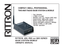
1
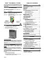
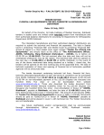
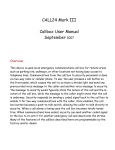
® Vandal-Resistant Wireless Callbox Owners Manual ( P R E L I M I N A RY ) Ritron Pub. 14500028 TRAILS MARINAS SCHOOLS HOSPITALS CAMPUSES ROADSIDES PUBLIC PARKS PLAYGROUNDS CAMPGROUNDS GOLF COURSES HOTELS/ MOTELS PUBLIC BEACHES SHOPPING MALLS AMUSEMENT PARKS PARKING FACILITIES UNATTENDED GATES Rev. C 08-02 Copyright© 2002 RITRON, INC. ALL RIGHTS RESERVED RITRON®, PATRIOT®, JOBCOM®, Quick Assist®, and Quiet Call® are registered trademarks of RITRON, INC. OUTPOSTTM and Quick TalkTM are trademarks of RITRON, INC. P.O. Box 1998, Carmel, IN 46082-1998 505 W. Carmel Dr., Carmel, IN 46032 USA PH: 317-846-1201; 800-USA-1-USA (800-872-1872) FAX: 317-846-4978 Web: www.radiocallbox.com E-mail: [email protected] WHAT THIS MANUAL COVERS This manual (Ritron Item: RQX-150/450/446/454-XT), covers programming, operation and installation of the OUTPOST XT 2Way Callbox. ACCESSORIES These replacement and optional items are available from Ritron and its authorized dealers. Item Description AFB-1545 EXPO-12 Standard 16 in. Flexible Whip Antenna External Power 12VDC Input/ Battery Back-Up Kit RAM-1545 Magnetic-Mount Antenna w/ 20 ft. of Cable and a BNC Connector ?? Optional Tamper-Resistant Enclosure + RECHARG EABLE + + + l l + + EXPO-12 EXTERNAL POWER/ BATTERY BACK-UP KIT RAM-1545 ANTENNA PHYSICAL DIMENSIONS The OUTPOST XT exterior dimensions are: 11.0" H x 9.25" W x 6.0" D. The OUTPOST XT weight is: 6.5 lbs w/o batteries. TABLE OF CONTENTS DESCRIPTION WHAT THIS MANUAL COVERS .................................... ii ACCESSORIES ............................................................. ii DIMENSIONS ................................................................ ii WARNINGS ................................................................... ii ABOUT THE OUTPOST XT WIRELESS CALLBOX ...... 1 General Information ............................................ 1 Operating the OutPost XT ................................... 2 Intercom (Always-on) Feature ............................ 2 Models and Frequencies .................................... 2 OUTPOST XT COMPONENTS ...................................... 3 IDENTIFICATION OF CONTROLS & CONNECTORS ................................... 4 INSTALLING BATTERIES INTO THE OUTPOST ................................................. 5 BATTERY LIFE ............................................................... 5 PTT PROGRAMMING THE OUTPOST XT (RQX-150/450/446 ONLY) ................................... 6 To Place the OUTPOST XT into Programming Mode ................................. 6 To Program a Frequency and QC Tone .............. 6 PC PROGRAMMING THE OUTPOST XT (RQX-150/450/454) ............................................. 7 REPROGRAMMING THE AUTOMATIC SHUT-OFF TIME ..................................................................... 8 MOUNTING THE OUTPOST XT ..................................... 8 To Mount the OutPost XT ..................................... 8 Coverage ............................................................. 8 EXPO12 EXTERNAL POWER 12 VDC INPUT/ BATTERY BACKUP KIT (OPTIONAL) ......................... 9 Back-Up Battery Installation ............................... 9 SEALING THE INTERNAL ANTENNA ........................... 10 External Power/Antenna Use ............................. 10 FCC REQUIREMENTS .................................................. 11 LIMITED WARRANTY ................................................... 11 COMPATIBLE PRODUCTS AND SYSTEMS ................. 12 DESCRIPTION Power Requirements (6) D Cell Alkaline Batteries (not included), or optional EXPO-12 External Power 12VDC Input/Battery Backup Kit. Refer to page 3 of the OUTPOST XT Owners Manual for battery information and page 7 of the OUTPOST XT Owners Manual for information on the EXPO-12. WARNING IMPORTANT SAFETY INFORMATION NOTICE: The Outpost XT is not intended for communicating information to protect life or property, and must not be used for these purposes. To reduce the risk of fire, electric shock or personal injury, follow these basic safety instructions when using this unit: 1. Read and follow all instructions. 2. Use only alkaline D-cell batteries. 3. During thunderstorms, avoid contact with this unit and any external antenna system or wiring. Page ii PAGE FIGURES PAGE A: OUTPOST XT COMPONENTS ................................. 3 1: TOP HALF OF INTERNALHOUSING CONTROLS & CONNECTORS ............................. 4 2: BOTTOM HALF OF INTERNAL HOUSING, SHOWING CELL POLARITY ................................ 5 3: REAR VIEW OF THE OUTPOST XT HOUSING ......... 8 4: INTERNAL VIEW OF EXPO-12 ................................. 9 5: SEALING THE INTERNAL ANTENNA ....................... 10 DESCRIPTION TABLES PAGE 1: FREQUENCY CODES ................................................ 5 2: QUIET CALL TONE CODES ...................................... 6 ® OutPost XT Owners Manual ABOUT THE OUTPOST XT TAMPER-RESISTANT WIRELESS CALLBOX GENERAL INFORMATION: The OutPost XT is a ruggedized version of the popular OutPost Callbox. The XT model consists of four basic components: · External, rugged, fiberglass XT enclosure with pre-drilled mounting holes, inserts and mounting ears. · Vandal-resistant stainless steel faceplate with stainless steel vandal-resistant PTT (push-to-talk) button. · Internal, weather-resistant, sealed, and gasketed RF electronics enclosure with attached acoustic tube. · Internal flexible antenna with BNC connector. IMPORTANT NOTES: Refer to FIG.-A, page 3. 1. The external XT fiberglass enclosure itself is not designed to provide a complete weather-resistant seal, therefore, weep holes in the XT enclosure will allow moisture and/or condensation to escape. 2. The external fiberglass XT enclosure has pre-drilled mounting holes with inserts on the rear of the enclosure. DO NOT drill or penetrate the external XT enclosure for mounting purposes. Use only the pre-drilled holes for mounting the fiberglass XT Callbox. See page 8 of manual for details. 3. The internal RF electronics enclosure is mounted inside the XT enclosure and is designed to provide a weather-resistant seal. The internal RF electronics package has a top and bottom half. The enclosure is gasketed and held together with four captive screws in the top half (Do Not remove the screws from top half). The RF electronics are contained in the top half and the battery or optional external power kit are contained in the bottom half. Take care when re-assembling this enclosure to carefully seat the top half with the recessed area and gasket into the bottom half. Make sure the black strain relief nut is properly tightened around the PTT cable assembly to insure weather resistant seal. DO NOT pinch gasket, overtighten, cross- thread, strip, or remove captive screws. Failure to heed this warning will prevent proper sealing of the enclosure and will result in voiding Manufacturers Warranty. 4. Antenna - The OutPost XT Callbox comes standard with an internally mounted flex antenna (AFB-1545). This antenna will provide approximately ½ mile line-of-sight range or more depending on terrain. Optional (external) antennas can be used. However, the owner/dealer is responsible for making modifications (holes) to the XT enclosure to allow for external cabling of the antenna. Refer to page 10. Regardless of the antenna to be used, it is always best to seal the antenna connection using seal tape. Refer to page 10. WARNING! If the OutPost XT is to be used outdoors it is imperative that the antenna connection be sealed to prevent voiding Manufacturers Warranty. Take care to range test the OUTPOST XT before installing and thoroughly engineer the system BEFORE drilling or penetrating the XT enclosure. Please refer to page 10 for recommended practices and detailed information. DO NOT drill or penetrate the internal RF electronics enclosure with any additional holes. For assistance, call RITRON at 800-872-1872, or go to www.ritron.com Page 1 ® OutPost XT Owners Manual ABOUT THE OUTPOST XT TAMPER-RESISTANT WIRELESS CALLBOX 5. Power The standard OutPost XT will operate using 6 D size alkaline batteries. The OUTPOST XT can also be used with the optional External Power 12 VDC Input/Battery Backup Kit model EXPO-12. If external power (EXPO-12) is required the the owner/dealer is responsible for making modifications (holes) to the XT enclosure, please refer to page 10 for recommended practices and detailed information. Warning! Take care and thoroughly engineer the system BEFORE drilling or penetrating the XT enclosure. Caution - If both external antenna and external power are required in the same callbox DO NOT co-locate the antenna and power cable in the same conduit. Run separate conduit for each cable. OPERATING THE OUTPOST XT NOTE: The OUTPOST XT will not receive a call until a call has been initiated by the OUTPOST XT. THE OUTPOST XT AUTOMATICALLY SHUTS OFF WHENEVER THERE IS INACTIVITY FOR TEN (10) SECONDS. To Initiate a Call: Press and hold the ON/PTT Button on the unit, listen for the beep, and begin speaking into the MIC. For best communication, speak as closely as possible into the microphone. The OUTPOST XT is designed so you will be heard clearly when you speak, while pressing the ON/PTT Button, at a distance of up to 3 feet from the microphone. To Receive a Response: 1. When you have finished speaking, release the ON/ PTT Button. 2. Any reply to you will be heard through the OUTPOST XT speaker. If a reply is not received within 10 seconds of releasing the ON/PTT Button, the unit sounds a low double tone and shuts off automatically. To call again, press and hold the ON/PTT Button and begin speaking after the beep. INTERCOM (Always-On) FEATURE FOR THE RQX-454/454-N-XT The RQX-454/454-N-XT can be programmed to operate as a two-way intercom. When this feature is activated the automatic shut-off is disabled and the callbox will remain on in standby mode allowing it to receive a call from another radio at any time. Since the radio is under constant current drain always on in the standby mode, it would make the use of batteries impractical. When using this feature, it is recommended that the optional EXPO-12 external power kit be used. To Enable the Intercom Feature: The Intercom Mode can only be enabled using the PC Programmer (PC Programming Software RPT-PCPK-8.0R12). 1. Refer to the PC PROGRAMMING THE OUTPOST XT section to program the RQX-454/454-N-XT. 2. Once the radios information has been Read, select EDIT, select TUNE RADIO, select MISC, select Power Saver, select TUNE, set Power Saver Off Time to 0 (zero), select SAVE, select EXIT, and then remove power from the radio and disconnect the programming cable. The RQX-454/ 454-N-XT is now set for Intercom Mode. OUTPOST XT MODELS and FREQUENCIES Model Band Frequency Range Signalling Formats RQX-150-XT* VHF-FM 150155 MHz Std., 155160 MHz Opt. CTCSS RQX-450-XT* UHF-FM 460470 MHz Std., 450460 MHz Opt. CTCSS RQX-446-XT*** UHF-FM 460470 MHz, Wide or Narrow Band TX, 460 MHz Opt CTCSS/ DCS (1stQ 2002) RQX-454-XT** UHF-FM 450470 MHz Narrow Band CTCSS/ DCS/LTR, Passport RQX-454-N-XT** UHF-FM 450-470 MHz Narrow Band RX/TX CTCSS/DCS/LTR, Passport * The RQX150/ 450 Models are PTT-programmable to specific tones and channel frequencies. They are also PC programmable to any frequency channel within the radio's band, using the RPTPCPK3.0 R20, or higher, PC Software. ** The RQX454 models is PC-programmable ONLY and requires the RPTPCPK8.1R5, or higher, PC Software. ***The RQX-446 model is PTT-programmable and/or PC-programmable. Software is not available at time of printing. Call Ritron for details. Refer to page 6 for instructions on matching the OUTPOST XT operating frequency to that of an existing radio system. Page 2 For assistance, call RITRON at 800-872-1872, or go to www.ritron.com FIG.-A EXPLODED VIEW OF THE OUTPOST XT COMPONENTS TAMPER-RESISTANT FASTENERS (4) STAINLESS STEEL FACE PLATE SEALED RF ENCLOSURE CAPTIVE SCREWS (4) . INTERNAL MOUNTING PLATE & HARDWARE XT ENCLOSURE If the OUTPOST XT is to be used outdoors, it is imperative that the antenna and connector be sealed with seal tape. Use Grainger #2A-459, Radio Shack #278-1647, or equivalent. Refer to instructions on the seal tape package. Refer to page 10 ® OutPost XT Owners Manual Page 3 ® OutPost XT Owners Manual IDENTIFICATION OF INTERNAL CONTROLS AND CONNECTIONS Refer to FIG1. 1. ANTENNA CONNECTOR The antenna radiates radio signals. Before using the OUTPOST XT, make sure the antenna is securely fastened into the connector. If the OUTPOST XT is to be used outdoors, see page 10 for instructions on properly sealing the antenna connector. 2. PROGRAM BUTTON (RQX-XT-150/450) This button is used to enter frequency and Quiet Call code information. 3. OFF BUTTON (RQX-150/450) This button is used to turn the OUTPOST XT OFF when programming is complete. 4. PROGRAM SAVE BUTTON (RQX-150/450) This button is used to save the programmed information. 5. PROGRAM ENABLE BUTTON (RQX-150/450) Pressing this button when the unit is ON puts the OUTPOST XT into Programming Mode. NOTE: Model RQX-XT-454 must be programmed by a RITRON Dealer. 6. SPEAKER After a message has been sent from the OUTPOST XT, any reply from another radio may be heard through the speaker. 7. MICROPHONE ("MIC") For best communication, speak as closely as possible into the microphone. The OUTPOST XT is designed so you will be heard clearly when you speak, while pressing the ON/PTT Button, at a distance of up to 3 feet from the microphone. 8. IN-LINE BATTERY CONNECTOR The in-line battery connector connects the radio to the Battery. 9. PRE-DRILLED MOUNTING HOLES Mounting holes accommodate #6 panhead screws to securely mount the unit to a variety of surfaces. Refer to page 5, FIG-2. 10. BATTERY HOLDER The rugged battery holder securely holds six (6) D-cell batteries in place. Refer to page 5, FIG-2. 1. ANTENNA CONNECTOR 2. PROGRAM BUTTON 3. OFF BUTTON 4. SAVE BUTTON 5. ENABLE BUTTON ACUSTIC TUBE 6. SPEAKER 7. MICROPHONE LIQUID TIGHT STRAIN RELIEF 8. IN-LINE BATTERY CONNECTOR CAPTIVE SCREWS (4) (Front View of Top Half) (SEE PAGE 5 FOR ITEMS 9 AND 10) (Inside View of Top Half) FIG1: TOP HALF OF INTERNAL HOUSING CONTROLS & CONNECTORS Page 4 ® OutPost XT Owners Manual INSTALLING BATTERIES INTO THE OUTPOST XT Refer to FIG.-1 and FIG2. 1. Using the T-25 Tamper-Proof Torx driver, remove the (4) Tamper-Proof Torx screws from the steel front plate. 2. Lift the steel front plate from the OUTPOST XT enclosure to expose the OUTPOST Callbox mounted inside. 3. Use a medium Philips screw driver to complete the battery installation loosening the four (4) plastic screws at the corners of the front half of the housing. These screws are captive to the Housing; to prevent damaging them, DO NOT remove them. 4. Disconnect the in-line connector between the Front and the Back halves of the Housing. 5. Note the positive and negative polarities ("+" and "") of each cell. Press six Alkaline D-cells into proper position. NOTE: When all batteries are in place, confirm that the RED wire contacts the positive (+) pole of the first battery, and the BLACK wire contacts the negative () pole of the last battery, as shown in FIG2. 6. Reconnect the in-line connector between the Front and the Back halves of the Housing. 7. After re-assembling the OUTPOST Callbox inside the OUTPOST XT enclosure, place the steel front plate on the enclosure. To prevent voiding Manufacturers Warranty, DO NOT pinch gasket, over tighten, crossthread, strip, or remove captive screws. DO NOT drill or penetrate the internal RF electronics enclosures with any additional holes. 8. Secure the steel front plate with the (4) TamperProof Torx screws with the T-25 Tamper-Proof Torx Driver. Take care when re-assembling this enclosure to carefully seat the top half with the recessed area and gasket into the bottom half. 9. PRE-DRILLED MOUNTING HOLES (4 CORNERS) RED WIRE (+) ! ! WARNING ! ! DO NOT USE NICKEL METAL HYDRIDE BATTERIES IN THE OUTPOST. BLACK WIRE () 10. BATTERY HOLDER IN-LINE CONNECTOR (INSIDE VIEW) FIG2: BOTTOM HALF OF INTERNAL HOUSING, SHOWING CELL POLARITY BATTERY LIFE Use non-rechargeable Alkaline D-cell batteries for maximum battery life. The OUTPOST XT should operate for one (1) year on a set of Alkaline batteries, depending upon usage. Cooler temperatures degrade battery life. Exposure to 10° C (50° F) will reduce battery life to 90% of normal. Exposure to 20° C (4° F) will reduce battery life to 35% of normal. For assistance, call RITRON at 800-872-1872, or go to www.ritron.com Page 5 ® OutPost XT Owners Manual HOW TO PTT PROGRAM THE OUTPOST XT (MODELS RQX-150/450/446 ONLY ) NOTES: Refer to Table 1 (Frequency Codes) and Table 2 (QC Tone Codes) when programming the OUTPOST. For PROGRAMMING BUTTON locations, refer to the Internal View of the Front of the Housing in FIG1, page 4. Before you begin the programming process refer to page 3 for disassembly of the XT enclosure. To place the OUTPOST into Programming Mode: 1. Loosen the (4) plastic screws in the corners of the unit. These screws are captive to the Housing; to prevent damaging them, DO NOT remove the captive screws from the housing. Program 44 to enter No Tone for Quiet Call. You must enter 44 to match radios without tone codes. If you make a programming click error, press and 2. Make sure the unit has batteries installed. NOTE: The voltage of the batteries must be greater than 6 VDC to program properly. 3. Press and release the ON/PTT Button on the front of the unit. 4. Press and release the PROGRAM ENABLE BUTTON. An audible beep will sound to confirm the unit is in programming mode. To read out (beep out) Radio Channel content: 5. Press and release the Program Save Button. The radio will begin to sound a series of beeps; each series of beeps is equal to one digit of each 2-digit frequency code or Quiet Call Code (see chart below) that is programmed into the radio. See Tables 1 and 2 on this page. 6. After the beeps are completed, a triple tone will sound. To Program Frequency and QC Tone Codes: 7. Choose a frequency code (Table 1) and, if desired, a QC tone code (Table 2). If you are not using a QC tone, program 44 (No Tone) for the QC code. 8. Enter the codes in the sequence shown below by clicking the PROGRAM BUTTON the number of times equal to each digit of the codes. EXAMPLE: Frequency Code 02, Tone Code 44 Click the PROGRAM BUTTON ten times to program 0, pause; the unit sounds a beep. Click the PROGRAM BUTTON two times to program 2, pause; the unit sounds a beep. Click the PROGRAM BUTTON four times to program 4, pause; the unit sounds a beep. Click the PROGRAM BUTTON four times to program 4, pause; the unit sounds a beep. FREQUENCY CODE "02" 1st (pause) digit 2nd digit 0 2 9. (pause) TONE CODE "44" (pause) 1st digit (pause) (pause) 4 (pause) 2nd (pause) digit 4 (pause) When all four digits are programmed, press and release the PROGRAM SAVE Button. The unit sounds a triple tone. NOTE: An error tone sounds if you try to save an incorrect digit. To correct the programming, press and release the PROGRAM OFF BUTTON. When the unit sounds a low tone, you may start over at Step #3. 10. Press and release the PROGRAM OFF BUTTON; the unit sounds a low tone. The OUTPOST is now ready for use. NOTES: Page 6 Ten (10) clicks = 0 (zero). release the PROGRAM OFF BUTTON to turn the unit OFF, and start over. If the unit does not sound the confirming triple tone when you attempt to save your programming, the unit was factory- or dealer-customized to disable programming. Consult the radio owner, or your Dealer. Refer to Frequency and Tone Code tables at right and on the following page. TABLE 1: FREQUENCY CODES (VHF Business Band) VHF Business Band Model RQX-150 MHz 01 02 03 04 154.600 ..... 154.570 ..... 151.625 ..... 151.955 ..... 05 06 07 08 151.925 154.540 154.515 154.655 09 10 11 12 151.685 151.715 151.775 151.805 13 14 15 16 151.835 151.895 154.490 151.655 17 18 151.745 151.865 Frequency Color Green Dot Blue Dot Red Dot Purple Dot (UHF Business Band) QUICK TALK FREQ. CODE UHF Business Band Model RQX-450 MHz Frequency Color 01 02 03 04 467.7625 ..... 467.8125 ..... 464.5500 ..... 464.5000 ..... J K Yellow Dot Brown Dot 05 06 07 08 467.8500 ...... Silver Star 467.8750 ...... Gold Star 467.9000 ...... Red Star 467.9250 ...... Blue Star 09 10 11 12 469.2625 462.5750 ...... White Dot 462.6250 ...... Black Dot 462.6750 ...... Orange Dot 13 14 15 16 464.3250 464.8250 469.5000 469.5500 17 18 19 20 463.2625 464.9125 464.6000 464.7000 ® OutPost XT Owners Manual TABLE 2: QUIET CALL TONE CODES QUICK TALK QC CODE 01 02 03 04 05 06 07 08 09 10 11 12 13 14 15 16 17 18 19 20 21 22 23 24 25 26 Freq. ( Hz ) 67.0 71.9 74.4 77.0 79.7 82.5 85.4 88.5 91.5 94.8 97.4 100.0 103.5 107.2 110.9 114.8 118.8 123.0 127.3 131.8 136.5 141.3 146.2 151.4 156.7 162.2 Other Radio Brands Tone Code QUICK TALK QC CODE XZ XA WA XB SP YZ YA YB ZZ ZA ZB 1Z 1A 1B 2Z 2A 2B 3Z 3A 3B 4Z 4A 4B 5Z 5A 5B 27 28 29 30 31 32 33 34 35 36 37 38 39 40 41 42 43 *44 45 46 47 48 49 50 51 Freq. ( Hz ) Other Radio Brands Tone Code 167.9 173.8 179.9 186.2 192.8 203.5 210.7 218.1 225.7 233.6 241.8 250.3 69.4 159.8 165.5 171.3 177.3 No Tone 183.5 189.9 196.6 199.5 206.5 229.1 254.1 6Z 6A 6B 7Z 7A M1 -------------------- * Use Code "44" to program No Tone for systems without a Coded Squelch Interference Eliminator feature. Refer to Page 4, Step 5 and NOTES at the bottom of the page. HOW TO PC PROGRAM THE OUTPOST XT ( RQX-150/450/446/454-XT) Dealers and Authorized Service/ Maintenance Personnel Only If your frequency is not found in Table 1, page 4, the frequency and tone must be programmed with a PC using specialized RITRON Programming Software. NOTE: Only RITRON dealers have access to programming software. Contact RITRON at 800-USA-1-USA for the location of your nearest Authorized RITRON Dealer. Models RQX-150-XT & RQX-450-XT require remove the screws from the housing. 3. Lift the top half of the RF enclosure from the bottom. 4. Remove the (4) metal seal screws from the front of the top half of the RF enclosure. 5. Carefully lift the radio assembly away from the inside of the front of the RF enclosure and plug the Programming Cable adaptor into the 3.5mm Jack located on the top of the radio assembly. 6. Execute the Programming Software for the radio on your computer. 7. Make sure the radio has batteries installed or is powered by an external 12 VDC source through the EXPO-12. To turn the unit on, press the ON/ PTT button on the front of the unit. 8. Follow the instructions for PC programming the radio according to the software. When PC Programming: the VHF RQX-150-XT will read out as a model SST-150 the UHF RQX-450-XT will read out as a model SST-450 the UHF RQX-446-XT will read out as a model RQX-446 the UHF RQX-454-N-XT will read out as a model SST-454 WARNING: ONLY FREQUENCY AND TONE INFORMATION should be altered when using the RITRON Programming Software!!! Changes to other features could render the unit inoperable. 9. After the programming is complete and the information has been saved to the radio, unplug the radio from the battery holder or the EXPO-12 and remove the Programming Cable Adaptor. 10. Plug the battery cable or the EXPO-12 Power Connector back into the radio. 11. Carefully place the radio assembly into the front case and secure it with the (4) metal seal screws. 12. Secure the top of the RF enclosure to the bottom of the Callbox with the (4) captive screws. NOTE: The antenna may be positioned to either side of the RF enclosure. 13. After re-assembling the RF enclosure, place the steel front plate on the enclosure. 14. Secure the steel front plate with the (4) TamperProof Torx screws with the T-25 Tamper-Proof Torx Driver. RPTPCPK3.0 R19 PC for PC programming. Models RQX-454/454N-XT require RPT-PCPK8.0R12 for PC programming. Model RQX-446-XT requires PC software not available at time of printinng. Please contact RITRON for further details 1. Follow instructions from page 6, steps 1-3. 2. Loosen the (4) captive screws in the corners of the RF enclosure. These screws are captive to the housing; to prevent damaging them, DO NOT For assistance, call RITRON at FACTORY DEFAULT Unit is set for medium volume. Battery saver "Auto Shut-off" is set for 10 seconds. 800-872-1872, or go to www.ritron.com Page 7 ® OutPost XT Owners Manual REPROGRAMMING THE AUTOMATIC SHUT-0FF TIME RQX-150/450 Standard and XT Models: Use PC Programming Software RPT-PCPK-3.0R19. RQX-454 Standard and XT Model: Use PC Programming Software RPT-PCPK-8.0R12. 1. Refer to the Owners Manual for disassembly instructions to PC Program the radio. 1. Refer to the Owners Manual for disassembly instructions to PC Program the radio. 2. Execute the Programming Software and go to the Main Menu page. 2. Execute the Programming Software and go to the Main Title Page. 3. Click on Plus-Series, then click on Start. 4. Plug the programming cable into the RQX and power the RQX by pressing the button on the front case. 5. Click on Radio, then click on Read Radio. 3. Plug the programming cable into the RQX and power the RQX by pressing the button on the front case. 4. Press 1 to read the RQX information. 5. The RQX-150/-XT will read out as a Model SST-150. The RQX-450/-XT will read out as a Model SST-450. 6. Use the down arrow key or enter key to get to the Access Radio Tech Fields field. 7. Type tune!. 8. The cursor should automatically go to the Battery Saver Off time field. 9. The factory default time is 10 seconds. Type in the time(in seconds from 1 to 256) for your desired shut-off time. NOTE: DO NOT type 0 for the Battery Saver Off Time unless your RQX has a label marked 314G0158 on the outside of the case. Doing so will render the RQX inoperable. Units that do not have the 314G0158 label do not contain the necessary firmware for the On all the time option. 10. Press the F10 key. 11. Press 2. 12. Wait for the next prompt, press C. 13. Wait for the radio programmed ok message. 12. Remove the power from the RQX and unplug the RQX from the computer. MOUNTING THE OUTPOST XT CALLBOX The external fiberglass XT enclosure has pre-drilled mounting holes with inserts on the rear of the enclosure. To prevent voiding the Manufacturer Warranty. DO NOT drill or penetrate the external XT enclosure for mounting purposes. Use only the pre-drilled holes for mounting the fiberglass XT Callbox. 6. The RQX-454 will read out as a Model RQX-454. 7. Click on Edit, then click on Tune Radio. 8. Click on Misc. 9. Click on Power Saver Off Time, then click on Tune. 10. To calculate the decimal number for your desired off time, divide your desired time (in seconds) by 32. Round the number to two places pass the decimal point. Example: 10 seconds(factory default) divided by 32 = .31 NOTE: 1. The maximum amount of shut-off times is 255 seconds. 2. DO NOT type 0 for the Battery Saver Off Time unless your RQX-454 has firmware version 1.14 or later. Doing so will render the RQX inoperable. Units that do not have version 1.14 or later do not contain the necessary firmware for the On all the time option. To check, click on Edit, then click on Radio ID. 11. Type in your decimal number. 12. Click on Save. 13. Click on Exit. 14. Remove the power from the RQX and disconnect the RQX from the computer. PRE-DRILLED HOLES WITH INSERTS (4 CORNERS) USE ONLY FOR MOUNTING MOUNTING EARS (4 CORNERS) The OUTPOST XT can be mounted to virtually any surface by using (4) #10-32 Panhead screws secured into the 4 corner rear inserts, or by using the enclosed metal mounting ears that are secured using the included (4) #10-32 Panhead screws. If the metal mounting ears are used, use a maximum size of 5/16 diameter bolts to mount the OUTPOST XT. The OUTPOST XT is designed to be mounted vertically. The drain holes are located on the bottom of the enclosure to allow for moisture to escape that may occur during outdoor use. Coverage Depending on unit location and installation height of a standard antenna, the OUTPOST XT covers the area of a 1-Watt portable radio of the same frequency band. To increase range, use an external antenna that is mounted higher. Refer to the RAM1545 Magnet Mount Antenna on page ii. Page 8 FIG3: REAR VIEW OF THE OUTPOST XT ENCLOSURE ® OutPost XT Owners Manual EXPO-12 EXTERNAL POWER 12VDC INPUT/ BATTERY BACK-UP KIT (OPTIONAL) The optional EXPO12 will facilitate powering the 2-Way Radio Transceiver in the RQX OUTPOST Callbox from an external 12 VDC source. Battery back-up capability is a standard feature of the EXPO-12. A 12 VDC, 1.5 Ampere power supply (not included with the EXPO-12) is required. The optional AC to 12 VDC RPS-EX wall transformer is available from Ritron. The Battery Back-up feature of the EXPO-12 allows the OUTPOST Callbox to continue operating for a period of 8 hours talk time if external power is interrupted. Either non-rechargeable 6 AA Alkaline, Lithium, or re chargeable Ni-cd batteries can be used. By moving jumper PJ101 on the EXPO12 Board, rechargeable batteries can be trickle-charged. Refer to the illustration below, Jumper Position "A.". NOTE: DO NOT attempt to charge Alkaline batteries. Back-Up Battery Installation 1. Remove the four (4) #4 screws securing the metal plate covering the battery holder. 2. Install the desired batteries, rechargeable or nonrechargeable (see Notes below and at right). Match polarities of the battery to the Battery Holder, as shown below. NOTES: For rechargeable batteries, use ONLY AA-size Ni-cd (Nickel Cadmium) cells. For non-rechargeable batteries, use ONLY AA-size Alkaline or Lithium cells. DO NOT USE Nickel Metal Hydride cells. DO NOT drill or penetrate the internal RF electronics enclosure with any additional holes. Use only pre-drilled mounting holes. 3. Place the jumper over the correct two PJ101 pins for the batteries you are using (rechargeable or non-rechargeable). See PJ101 location below. NOTES: When the OUTPOST has rechargeable batteries installed, place the PJ101 jumper in position "A". When the OUTPOST has non-rechargeable batteries installed, to prevent damaging the batteries, place the PJ101 jumper in the position "B", over two pins. 4. Reinstall the metal plate removed in Step 1; secure it with the four (4) #4 screws. 5. Make sure the black strain relief nut is properly tightened around the PTT cable assembly to insure weather reisistant seal. PRE-DRILLED MOUNTING HOLES (4 CORNERS) JUMPER POSITION "A" ( PJ101 JUMPER SET IN RECHARGEABLE POSITION) BATTERY HOLDER Due to space limitations in the XT model, the installation of the liquid tight strain relief must be reversed. + PJ101 + + JUMPER POSITION "B" ( PJ101 JUMPER SET IN NON-RECHARGEABLE POSITION ) + + + AA-SIZE CELLS (6) PJ101 LIQUID TIGHT STRAIN RELIEF WIRES FROM EXTERNAL POWER SOURCE POSITIVE POWER CONNECTION (+) NEGATIVE POWER CONNECTION (-) POLARIZED IN-LINE BATTERY CONNECTOR FIG-4: INTERNAL VIEW OF EXPO12 (COVER PLATE NOT SHOWN) For assistance, call RITRON at 800-872-1872, or go to www.ritron.com Page 9 ® OutPost XT Owners Manual HOW TO PROPERLY SEAL THE INTERNAL ANTENNA 1. DO NOT drill or penetrate this enclosure. Use only the pre-drilled mounting holes located in each of the four corners of the bottom half of the enclosure. Take care when re-assembling the enclosure. Be sure to carefully seat the recessed area and gasket of the top half with the bottom half. DO NOT pinch gasket, over tighten, crossthread, strip or remove captive screws. 2. Antenna - The product comes standard with a flex antenna (Model AFB-1545) with a BNC connector. This antenna will provide approximately ½ mile or more range in line-of-sight conditions with no-obstacles. Optional Antennas The Ritron model RAM-1545 magnet mount antenna can be used to increase range. Be advised that the magnet mount antenna MUST be attached to a magnetic ground plane (metal) to function properly. SEALING THE ANTENNA - If the product is to be used outdoors it is imperative that the entire antenna connection be sealed with seal tape to provide proper operation and prevent voiding warranty. Regardless of the antenna you use, it is always best to weatherproof the antenna connection using seal tape. Applying Seal Tape: 1. Attach the antenna to the connector on the OUTPOST RF enclosure and position at the elbow into a 90° angle. 2. Begin wrapping seal tape at base of antenna connector such that the base of the antenna is sealed against the enclosure top. 3. Overlap the seal tape as you wrap upward around the connector and antenna. Continue to overlap seal tape around the connector base, past the articulating portion of the antenna and several inches up the thin, shiny section of the antenna. BEFORE SEALING Overlap sealing tape to include the antenna connection and the top of the RF enclosure 5 ½ min AFTER SEALING Overlap sealing tape (1) inch beyond the rigid section of the antenna Seal tape can be purchased at most Industrial & Contractor Supply Stores, Hardware and Home Center Stores or Electronic Supply Stores. NOTICE: Failure to follow these instructions will cause damage to the product, prevent proper sealing of the enclosure and will void the Manufacturers Warranty. RECOMMENDATIONS FOR EXTERNAL POWER/ANTENNA USE 1. Do not route external 12 VDC power cable and external antenna cable through the same conduit. 2. It is recommended that metal conduit fittings and metal conduit be used to route either external power and/ or external antenna cable to maintain vandal-resistance integrity. 3. It is recommended that a standard BNC male connector be used to mate with the BNC connector located on the internal RF electronics enclosure. 4. If installing an external antenna form a drip loop using the antenna cable inside the XT enclosure. Position the drip loop below and away from the BNC connector located on the top of the internal RF electronics enclosure. Page 10 ® OutPost XT Owners Manual F.C.C. LICENSING AND REGULATIONS The Rules and Regulations of the United States Federal Communications Commission (FCC) require you or your radio service provider to have a license for your radio system before activating the OUTPOST XT radio transmitter. If you already are operating a licensed radio system, you probably can add a OUTPOST XT without any changes to that license. The station licensee is responsible for ensuring that transmitter power, frequency and modulation are within the limits specified by the station license, and also for proper operation and maintenance of the radio equipment. These responsibilities include checking the transmitter frequency and modulation periodically, using appropriate methods. Ritron or your Ritron Dealer can assist you with all these requirements. You may also contact the FCC directly by any of the following methods: To obtain copies of FCC forms and instructions use the FCC Fax-On-Demand system at 202-418-0177. Request Document 000600. For more information, go to the FCC Internet Website at: < http/www.fcc.gov > DO NOT allow the antenna to come very close to, or to touch exposed parts of the body, especially the face or eyes, while transmitting. DO NOT transmit near electrical blasting caps or in an explosive atmosphere. DO NOT allow children to play with radio transmitters. BE AWARE of the conditions which cause the unit to transmit. SERVICE - Federal law prohibits you from making any internal adjustments to the transmitter, and from changing transmit frequencies unless you are specifically designated by the licensee. DO NOT ADJUST OR TAMPER with components or the printed circuit board in any manner not directed in this manual. Unauthorized adjustments may render the unit inoperable; repair will be at owner's expense. If your radio equipment fails to operate properly, or if you wish to have the radio serviced, contact your authorized dealer, or call Ritron at 317-846-1201 and ask for the Repair Department. SAFETY STANDARDS The FCC has adopted a safety standard for human exposure to radio frequency electromagnetic energy emitted by FCC regulated equipment. The Quick Talk conforms to the standards effective at the time of its equipment authorization by the FCC. In general these standards recommend that you: RITRON, INC. LIMITED WARRANTY WHAT THIS WARRANTY COVERS: RITRON, INC. ("RITRON") provides the following warranty against defects in materials and/or workmanship in RITRON RQX-150-XT, RQX-450-XT, RQX-446-XT, AND RQX-454-XT Wireless Callbox units under normal use and service during the applicable warranty period, as stated below. "Accessories" means antennas, wire, cable and items contained in the programming and programming/service kits. WHAT IS COVERED FOR HOW LONG OutPost XT Callboxes Accessories/Antennas 1 year * 90 days * WHAT RITRON WILL DO During the first year after date of purchase, RITRON will repair or replace the defective product, at RITRON's option, parts and labor included at no charge. * After date of purchase WHAT THIS WARRANTY DOES NOT COVER: Any technical information provided with the covered product or any other products; Installation, maintenance or service of the product, unless this is covered by a separate written agreement with RITRON; Any products not furnished by RITRON which are attached or used with the covered product, or defects or damage from the use of the covered product with equipment that is not covered; Defects or damage, including broken antennas, resulting from: - misuse, abuse, improper maintenance, alteration, modification or modification to any housing, neglect, accident or act of God, or, - the use of covered products other than in normal and customary manner, or, - improper testing or installation; Defects or damages from unauthorized disassembly, repair or modification, or where unauthorized disassembly, repair or modification prevents inspection and testing necessary to validate warranty claims; Defects or damages in which the serial number has been removed, altered or defaced. IMPORTANT: This warranty sets forth the full extent of RITRON's express responsibilities regarding the covered products, and is given in lieu of all other express warranties. What RITRON has agreed to do above is your sole and exclusive remedy. No person is authorized to make any other warranty to you on behalf of RITRON. Warranties implied by state law, such as implied warranties of merchantability and fitness for a particular purpose, are limited to the duration of this For assistance, call RITRON at limited warranty as it applies to the covered product. Incidental and consequential damages are not recoverable under this warranty (this includes loss of use or time, inconvenience, business interruption, commercial loss, lost profits or savings). Some states do not allow the exclusion or limitation of incidental or consequential damages, or limitation on how long an implied warranty lasts, so the above limitations or exclusions may not apply to you. Because each covered product system is unique, RITRON disclaims liability for range, coverage, or operation of the system as a whole under this warranty. WHO IS COVERED BY THIS WARRANTY: This warranty is given only to the purchaser or lessee of covered products when acquired for use, not resale. This warranty is not assignable or transferable. HOW TO GET WARRANTY SERVICE: To receive warranty service, you must deliver or send the defective product, delivery costs and insurance prepaid, within the applicable warranty period, to RITRON, INC., 505 West Carmel Drive, Carmel, Indiana 46032, Attention: Warranty Department. Please point out the nature of the defect in as much detail as you can. You must retain your sales or lease receipt (or other written evidence of the date of purchase) and deliver it along with the product. If RITRON chooses to repair or replace a defective product, RITRON may replace the product or any part or component with reconditioned product, parts or components. Replacements are covered for the balance of the original applicable warranty period. All replaced covered products, parts or components become RITRON's property. RIGHTS TO SOFTWARE RETAINED: Title and all rights or licenses to patents, copyrights, trademarks and trade secrets in any RITRON software contained in covered products are and shall remain in RITRON. RITRON nevertheless grants you a limited non-exclusive, transferable right to use the RITRON software only in conjunction with covered products. No other license or right to the RITRON software is granted or permitted. YOUR RIGHTS UNDER STATE LAW: This warranty gives you specific legal rights, and you may also have other rights which vary from state to state. WHERE THIS WARRANTY IS VALID: This warranty is valid only within the United States, the District of Columbia and Puerto Rico. 800-872-1872, or go to www.ritron.com Page 11 ® OutPost XT Owners Manual Complete Wireless Communication Solutions From Ritron - We Build Wireless Solutions For nearly 3 decades Ritron has been designing, manufacturing, and supplying reliable, professional wireless communication products for users worldwide. Ritron wireless products will improve the operation, safety, and profitability of any organization by providing instant voice communication between key employees throughout the workplace. Portable Radios Communicate with multiple workgroups instantly with a push-of-the-button. Rugged and lightweight with built-in weather scan (VHF models only) automatically finds NOAA broadcasts. Other features include Interference Eliminator, Loud and Clear Audio, Removable Quick Swap Battery, and Drop-in Charging Capability. Accessories Ritron offers a wide variety of headsets, earsets, remote speaker microphones, multi-unit chargers, and carry holsters to meet all your wireless communication needs. A RITRON EXCLUSIVE Wireless Intercom/Two-way Base Station Monitor 110 VAC or 12 VDC desktop or wall mountable radio that is compatible with any VHF/UHF radio system. Includes built-in Weather Scan (VHF models only), loud audio output for noisy locations, built-in microphone with automatic gain control, and rugged metal housing. Optional Public Address (PA) modification available. Ideal for in-plant schools retail stores jobsite vehicles community repeater systems, loading docks construction trailers or anywhere that fixed two-way communication is needed. Page 12 ® OutPost XT Owners Manual The Leader in Workplace Two-Way Radio Systems Advantages of Ritron Wireless Products: Unique products and features not available from any other source Adds speed, flexibility, and responsiveness to any organization Fully compatible with virtually any existing two-way radio system Designed to work together as a complete system No mnothly service fees or airtime charges Made in the U.S.A. A RITRON Wireless Radio Callboxes Battery-operated (6 alkaline "D" cells) callboxes, available in basic or rugged models, provide instant wireless communication over existing two-way radio systems without costly trenching, extensive wiring, or dedicated phone lines. EXCLUSIVE Ideal for Hotels/Motels Golf Courses Schools, Public Parks Playgrounds Roadsides Marinas Parking Lots or Garages Receiving or Delivery Docks Campuses Shopping Malls Beachs and Pools Campgrounds and Hiking Trails Unattended Gates. TWO-WAY CALLBOX Wireless Alert Monitoring No need to run wires, phone lines, or pay a person for 24/7 monitoring. The low-cost, battery-operated (6 alkaline "AA" cells) Quick Talk Alert permits wireless monitoring of virtually any sensor or switch from a two-way radio. When the switch opens or closes, a user recordable "custom" voice message is automatically transmitted to all radios on the same channel frequency. ONE-WAY CALLBOX A RITRON EXCLUSIVE Ideal for remote monitoring of power failures liquid levels intrusion or tampering temperature sensing unattended doors to name only a few of the 1000s of applications. For assistance, call RITRON at 800-872-1872, or go to www.ritron.com Page 13 ® OutPost XT Owners Manual CARE AND MAINTENANCE MOISTURE When antenna sealing recommendations are followed, the OUTPOST XT is highly weather resistant in outdoor environments. Do not immerse the unit in water. TEMPERATURE The OUTPOST XT is designed to operate between 22° and +140° F. Like all electronic equipment, the OUTPOST XT should not be subjected to extreme heat. A shaded area is an ideal outdoor location. VIBRATIONS/ SHOCK Though the OUTPOST XT is designed to be rugged, it cannot be expected to survive extreme abuse. CHEMICALS Do not use harsh, corrosive or abrasive chemicals to clean the OUTPOST XT case; use only a cloth moistened with water. Do not attempt to clean the printed circuit boards inside the enclosure. ALL RITRON PRODUCTS ARE PROUDLY www.radiocallbox.com Ritron Pub. 14500028 Rev. C 08-02 P.O. Box 1998, Carmel, IN 46082-1998 505 W. Carmel Dr., Carmel, IN 46032 USA PH: 317-846-1201; 800-USA-1-USA (800-872-1872) FAX: 317-846-4978 Web: www.radiocallbox.com E-mail: [email protected] For assistance, call RITRON at 800-872-1872, or go to www.ritron.com Page 14