1
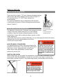
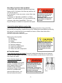
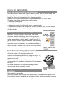
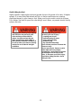
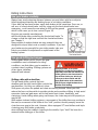
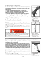
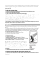
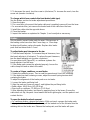
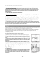
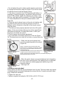
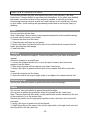
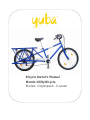
Bicycle Owner’s Manual
Mundo Utility Bicycle
Models: Singlespeed - 6-speed
IMPORTANT KEEP FOR FUTURE REFERENCE
About this Owner's Manual
This manual explains how to ride your new bike safely.
Even if you have ridden a bicycle for years, it is important for EVERY person to
read Chapter A before riding this bicycle!
Parents should explain Chapter 1 to a child or anyone else who might not otherwise
understand this information.
This manual also shows how to perform basic maintenance. Some maintenance should
only be performed by a professional bicycle mechanic, and the manual indicates these
tasks. If you choose to perform these tasks, you should purchase a detailed repair
manual from a bicycle dealer.
In this manual, the WARNING
sign indicates a hazardous
situation which, if not avoided,
could result in death or serious
injury.
In this manual, the CAUTION
sign indicates a hazardous
situation which, if not avoided,
may result in minor or
moderate injury
Register your bicycle
Bicycle registration is the only record we have of who owns this bike. If there is ever a
need to communicate with the owner, such as providing updated safety information,
your registration is crucial. There are two easy ways to register your new bicycle:
• By mailing the warranty card located in your box.
• By emailing your information to us [email protected] please mention date of
purchase, place of purchase, amount paid, name and ways to reach you and
model.
Assembly of your new bicycle
Assembly and the first adjustment of your bicycle take special tools and skills, it is
recommend that this should be done by a trained bicycle mechanic.
If you have any questions after reading the information in this manual, talk to your
dealer or us.
This manual conforms with these standards:
ANSI Z535.4
CPSC CFR 1512
BS 6102 : Part 1: 1992
CEN 14764, 14765, 14766, 14872
Table of Contents
IMPORTANT KEEP FOR FUTURE REFERENCE .........................................................2
About this Owner's Manual .....................................................................................2
Register your bicycle ...............................................................................................2
Assembly of your new bicycle .................................................................................2
Table of Contents .......................................................................................................3
CHAPTER 1: GUIDE TO SAFE ON-AND-OFF ROAD OPERATION.................................5
Bicycle type and use classification .............................................................................5
Condition 1..............................................................................................................5
Condition 2..............................................................................................................5
Before a first ride ........................................................................................................6
Make sure the bicycle fits........................................................................................6
Know how the bicycle performs ..............................................................................6
Check the bike before every ride ................................................................................7
RULES FOR SAFE RIDING .......................................................................................10
Know and observe local bicycle riding laws ..........................................................10
Watch for cars, pedestrians, and other obstacles .................................................10
Wear a helmet and proper cycling clothes ............................................................10
Change your riding to be safe in variable conditions .............................................10
Riding instructions ....................................................................................................13
Use your brakes carefully ......................................................................................13
Use good shifting techniques ................................................................................13
TAKE CARE OF YOUR BIKE.....................................................................................14
Protect your bike when parking or storing it ..........................................................14
Carry repair items ..................................................................................................14
Only install and use approved accessories ...........................................................14
Keep the bike clean...............................................................................................15
Avoid clamping the frame during transportation or repair .....................................15
Protect your bicycle during shipping .....................................................................15
Notice....................................................................................................................15
CHAPTER 2: MAINTENANCE.......................................................................................16
Maintenance schedule ..........................................................................................16
Recommended tools for proper bicycle maintenance ...........................................17
CHAPTER 3: ADJUSTMENT.........................................................................................18
Handlebar..............................................................................................................18
Stem......................................................................................................................18
Saddle...................................................................................................................19
Headset.................................................................................................................21
Crankset................................................................................................................21
Crank arms............................................................................................................21
Pedals ...................................................................................................................21
Bottom bracket .....................................................................................................21
Chain.....................................................................................................................21
-3-
Cables ...................................................................................................................22
Shifters ..................................................................................................................22
Front derailleur ......................................................................................................22
Rear derailleur .......................................................................................................23
To adjust the large cog position ............................................................................23
Brake levers ..........................................................................................................24
Brakes ...................................................................................................................25
Wheels ..................................................................................................................26
Suspension components.......................................................................................28
Accessories ...........................................................................................................28
CHAPTER 4: LUBRIFICATION......................................................................................29
Stem......................................................................................................................29
Seatpost................................................................................................................29
Bottom bracket .....................................................................................................29
Pedals ...................................................................................................................29
Derailleurs .............................................................................................................30
Headset.................................................................................................................30
Brakes and brake levers ........................................................................................30
Wheels ..................................................................................................................30
Suspension forks...................................................................................................30
Control cables .......................................................................................................30
CHAPTER 5: CARRYING LOADS WITH YOUR UTILITY BICYCLE ...............................31
About carrying a load by bicycle...............................................................................31
Getting to know your Utility Bicycle.......................................................................31
Seating on carrier seat ..........................................................................................31
Children.................................................................................................................31
Use good judgment...............................................................................................31
Pre-ride checklist ......................................................................................................31
Maximum payloads...................................................................................................32
Loading platforms .....................................................................................................32
Carrier : loading platform #1..................................................................................32
Sideloaders : lateral loading platforms #2 .............................................................32
Loading tips ..............................................................................................................32
Bike loading ..........................................................................................................32
Using the kickstand...............................................................................................32
Using a pole ..........................................................................................................33
Carrying longloads (ladder, kayak, solar panel) .....................................................33
Carrying groceries, or shopping ............................................................................33
Carrying passenger and children...........................................................................33
Cam straps............................................................................................................33
For more Information ................................................................................................34
Limited Warranty.......................................................................................................34
-4-
CHAPTER 1: GUIDE TO SAFE ON-AND-OFF ROAD OPERATION
Bicycle type and use classification
Riding a bicycle in a manner beyond, or more severe than, its intended use can cause
the bicycle or part of the bicycle to fail. The following information explains the type of
riding intended for different types of bikes. Read the safety information in Chapter 1 for
further details.
Condition 1
Bikes designed for riding on a paved surface where the tires do not lose ground
contact.
Condition 1 bike types
• Drop-type handlebars including touring bikes, but not cyclocross bikes
• Triathlon, time trial, or speed bikes
• Tandems of any design
• Cruisers with wide, 26" tires and swept-back handlebar
• Any bike that folds
• Weight limit: 275 lbs (125 kg); Tandems: 550 lb (250 kg)
Condition 2
Bikes designed for riding Condition 1, plus smooth gravel roads and improved trails
with moderate grades where the tires do not lose ground contact.
Condition 2 bike types
• Hybrid bikes with 700c wheels, tires wider than 28c, and flat handlebars
• City bikes- specially-equipped hybrids
• Cyclocross bikes- with drop-type handlebars, knobby 700c tires, and cantilever or
disc brakes
• Weight limit: 300 lbs (136 kg)
-5-
Before a first ride
Make sure the bicycle fits
There should be at least 1” (25 mm) clearance between the top
tube and the rider when standing over the bicycle (Figure 1).
For mountain bikes, 2-3” (50-75 mm) clearance is
recommended.
The seat and handlebar may be adjusted to offer the best
comfort and performance. Before making these adjustments,
refer to Chapter 3.
Figure 1- Minimum
stand-over height
A = 1" (25 mm) for most
bicycles
2-3" (50-75 mm) for
mountain bicycles
Know how the bicycle performs
The features of your bicycle, if misused, may cause you to lose
control of the bike. Before riding fast or in more difficult
conditions, learn the function and performance of all the
mechanisms of your bike by riding at slower speeds in a flat,
empty parking lot.
If you want your bicycle to perform differently, or if you have special needs that require
different parts for the safe operation of your bike,
consult your bicycle dealer.
Learn the power of your brakes
The stopping power on bikes varies according to the
intended use of the bike. If you would like your bike to
have more, or less, stopping power, consult your
dealer about brake adjustments or other brake
options for your bicycle.
Mis-use of the braking system,
including over-use of the front
brake, can cause you to lose
control and fall. Avoid improper
braking by understanding and
practicing proper application of
your brakes as explained in this
manual.
Avoid toe-clip overlap
When riding slowly, do not pedal if the handlebar is turned. It may be possible, at very
slow speeds, when the handlebar is turned, for your foot or toe-clips to contact the
front wheel or fender (Figure 2). At normal riding speeds, the handlebar does not turn
enough for this to occur.
Contact between your foot or
toe-clip and the front wheel or
fender can cause you to lose
control and fall. Avoid pedaling
when turning at slow speed.
figure 2- toeclip overlap
-6-
Stop riding if you have frame problems
Occasionally riders experience problems with their
frame or fork. If a frame or fork has any problem, do
not ride the bicycle.
As an example, in very rare cases, some riders may
experience
a “shimmy” or “harmonic oscillation” or “frame
vibration” at certain speeds. If you are experiencing
a shimmy, slow down immediately. Take your
bicycle directly to a dealer for inspection and repair.
A shimmy, or steering wobble,
can cause you to lose control
and fall. If you experience a
shimmy, slow down
immediately. Take your bicycle
to your dealer for inspection
and repair.
Check the bike before every ride
Before every ride, inspect the bike with the following check list. If any part of the
bicycle fails the inspection, repair the bicycle by following the information provided by
this manual, or take the bike to your dealer for service. Never ride a bike with a
damaged part; have it replaced.
This is not a comprehensive maintenance program
Before every ride checklist
Wheels
Tire inflation
Brakes
Handlebar and stem
Seat and seatpost
Suspension adjustments
Lights and reflectors
Frame, fork, and components
A bicycle that does not work
properly can cause you to lose
control and fall. Inspect the
entire bicycle thoroughly before
every ride, and do not ride it
until any problem has been
corrected
Check the wheels
Check that the wheels are straight. Spin each wheel and watch the rim as it passes
through the brake pads or the frame. If the rim wobbles up and down or from side to
side, repair the wheel.
Check that the wheels are
properly attached. Bicycle
wheels are attached by several
systems: threaded axle nuts, a
quick-release where a leveractuated wheel retention
mechanism (Figure 3) allows the
wheel to be installed and
removed without tools, or a
thru-axle where the axle is
A wheel attachment device that
is not properly adjusted and
closed may allow the wheel to
be loose or come off
unexpectedly, causing you to
lose control and fall. Make sure
the wheels are properly
attached before riding the bike.
-7-
Figure 3: -wheel quick
release
threaded through the ends of the frame or fork. For information about adjustment and
closure of the wheel attachment devices on your bicycle, see Chapter 3.
Test for proper wheel attachment. Pick up the bike and sharply hit the top of the tire
(Figure 4). The wheel must not come off, be loose, or move from side to side. Further
tests are provided in
Check the tire inflation
Inflate the tires to the air pressure recommended on the tire sidewalls.
ever ride a bike if you are not
certain the brakes are working
properly, or you if suspect a
problem with the brake cables
or hydraulic hose.
Malfunctioning brakes can
cause you to lose control and
fall. Inspect the brakes
thoroughly before every ride. If
your brakes are not working
properly, re-adjust them or take
the bike to your dealer for
service.
Check the brakes
Follow the inspection instructions for the type of brake
on your bike:
Hand-rim brake- a hand lever connected to the brake
by a cable causes the brake pads to squeeze the rim.
When the brakes are not applied, the brake pads
should be 1 to 2 mm from the rim.
Squeeze each brake lever toward the handlebar to
make sure the brake moves freely and stops the bike.
If the brake lever can be pulled to the handlebar, the
brake is too loose. If the brake pads are too close to
the rim, the brake is too tight. Brake pads should be
aligned with the rim surface (Figure 5).
Figure 5- Brake pad alignment
A- Brake pad aligned with rim
surface
B- Pad and rim should be
parallel
C- Direction of rim rotation
D- 0.5-1.0 mm toe-in
Disc brake- a hand lever connected to the brake
by a cable or hydraulic hose squeezes a disc
mounted on the wheel hub.
Squeeze each brake lever toward the handlebar to
make sure the brake moves freely and stops the
bike. If the brake lever can be pulled to the
handlebar, the brake is too loose. The brake pads
should be 0.25-0.75 mm away from the disc when
the brakes are not applied. If the pads are too
close, the brake is too tight, or mis-aligned.
-8-
Disc brakes and discs get very
hot during use and could burn
skin. Also, the disc edges may
be sharp and could cut skin.
Avoid touching the disc or disc
brake when hot, or when
rotating.
Check the seat and seatpost
Make sure the seat is secure by attempting to turn the seat and seatpost in the frame,
and attempt to move the front of the seat up and down. It should not move or be loose.
Check the lights and reflectors
Make sure the lights are functioning correctly and that any batteries are charged. If the
lights use a dynamo, make sure it is mounted correctly and all attachment hardware is
tight. Make sure reflectors are clean and in position.
Check frame, fork, and components
Carefully inspect your frame, fork, and components for signs of fatigue before and after
each ride. Regularly inspect your entire bicycle for signs of fatigue stress:
• Dents
• Cracks
• Scratches
• Deformation
• Discoloration
• Unusual noises
Even if you perform regular inspections, if you exceed the limit of strength of your
bicycle or a given part, it may fail if overloaded. After any high force load, thoroughly
inspect all the parts of your bike. High force loads include crashes, but you don't have
to crash to put a high force load on your bike. For example, hitting a large hole in the
road or a sharp bump such as a railroad track can put large forces on your bike.
The manner in which you ride will determine whether your bike and its parts will last. If
you ride hard or aggressively, you should replace the bike and/or its parts more often
than riders who ride smoothly or cautiously. There are many variables: weight, speed,
technique, terrain, maintenance, riding environment (humidity, salinity, temperature,
etc.), and the frame or part itself- so it is impossible to give a precise timetable for
replacement. If you aren't sure, ask your dealer. But as a rule, it is better to err on the
safe side and replace the bike or parts more frequently.
-9-
RULES FOR SAFE RIDING
Know and observe local bicycle riding laws
Most state and local areas have specific laws for cyclists, and you should follow them.
Local cycling clubs or your state’s Department of Transportation (or equivalent) should
be able to supply this information to you. The requirements
for items such as lights and reflectors change between areas, so check ahead.
These are a few of the more important rules of riding:
• Use proper hand signals.
• Ride single file when riding with other cyclists.
• Ride on the correct side of the road; never go against traffic.
• Ride defensively; expect the unexpected. A cyclist is hard to see, and many drivers
simply are not trained to recognize the rights and special considerations
of a bicycle rider.
Watch for cars, pedestrians, and other obstacles
Watch for and avoid potholes, drain grates, soft or low
shoulders, and other deviations which could impact your
wheels or cause them to slip. When crossing railroad tracks
or drain grates, do so carefully at a 90° angle (Figure 8). If
you are not sure of riding surface conditions, walk your bike.
If a car suddenly enters your lane, or someone unexpectedly
opens the door of a parked car, you could be involved in a
serious accident. Mount a horn or bell on your bicycle, and
use it to alert others of your approach.
Wear a helmet and proper cycling clothes
Wear a helmet that meets CPSC or CE safety testing
standards (Figure 9); it may help prevent injury.
Helmets should be removed when not riding the bicycle. If
the helmet is caught, stuck on, or stuck between objects, the
wearer could choke.
Wear protective clothing including helmet, eye protection,
and gloves. Avoid loose-fitting pants that could get caught in
the chain.
Also wear light, bright, and reflective clothing to make
yourself more visible, especially at night.
Change your riding to be safe in variable
conditions
Ride carefully in wet weather
No brakes, whatever their design, work as effectively in wet weather as they do in dry.
Even properly aligned, lubricated, and maintained brakes require greater lever pressure
- 10 -
and longer stopping distances in wet weather. Anticipate the extra distance it will take
to stop.
Wet weather causes reduced traction. Use slower cornering when traction is reduced,
such as when riding over wet leaves, painted crosswalks, or manhole covers.
When wet weather cools to below freezing, traction is reduced even further. In
addition, brakes may not work as well. Adjust your riding speed accordingly, or use
other forms of transportation.
When riding in wet weather, a dynamo (generator light) may not work properly. Avoid
riding in wet weather when visibility is reduced.
Strong winds can make a bicycle steer or turn unexpectedly. In windy conditions, slow
down or use other forms of transportation.
Be careful when riding in low light conditions.
Your bicycle is equipped with a full set of reflectors; keep them clean and in position.
As useful as these reflectors are, they do not help you see, nor do they help you be
seen unless light is directed on them. Use a working headlight and taillight when you
ride in poorly lighted or low visibility conditions. The important thing is to see and be
seen. If you do any amount of riding at dusk, at night, or in any poorly lighted
conditions, consult your dealer to find appropriate products to aid your vision and
make you more visible.
Do not use unsafe riding practices
Many cycling accidents could be avoided by using common sense. Here are a few
examples:
• Do not ride ‘no hands’.
• Do not ride with loose objects attached to the handlebar or any other part of the
bicycle.
• Do not ride while intoxicated or while using medications which might make you
drowsy.
• Do not ‘ride double’.
• Use special care when off-road riding. Ride only on the trails. Avoid rocks, branches,
or depressions.
When approaching a descent, reduce speed, keep your weight back and low, and use
the rear brake more than the front.
• Do not ride in an abusive manner; ride within the Use Classification for your type of
bicycle (see pages 1-2).
Bicycles are not indestructible. As with anything mechanical, every part of a bicycle
has a limited useful life due to wear, stress, and fatigue. Fatigue refers to a low-stress
force that, when repeated over a large number of cycles, can cause a material to fail or
break. The length of the life of a part varies according to its design, materials, use, and
maintenance. Although lighter frames or parts may, in some cases, have a longer life
than heavier ones, it should be expected that light-weight, high-performance bicycles
and parts require better care and more frequent inspections.
- 11 -
Avoid riding too fast
Higher speeds create higher risks and greater forces in the event of a crash. At higher
speeds, it is more likely that wheels will slip, or that a small bump can create a
significant impact to your frame or fork. Keep your bicycle under control at all times.
For children, the limit of speed for safe riding is much lower, so parents should strictly
enforce this rule.
A bicycle rider without proper lighting
and reflectors may not have good
vision and may not be visible to
others. Use front and rear bicycle
lights and reflectors when riding in
poor visibility conditions. Failure to do
so will increase your chances of being
involved in an accident in low light
conditions.
The following riding practices
increase your risk of injury:
• Jumping your bicycle
• Performing bicycle stunts
• Severe off-road riding
• Downhill riding
• Any abnormal bike riding
Each of these practices increases the
stress on every
part of your bicycle. Frames or parts
under high stress may fatigue
prematurely, causing them to fail and
increasing the risk of injury to the
rider. To decrease your risk of injury,
avoid these riding practices. Avoid
riding too fast.
- 12 -
Riding instructions
Use your brakes carefully
Always keep a safe stopping distance between you and other vehicles or objects.
Adjust stopping distances and braking forces to suit riding conditions.
If your bike has two hand brakes, apply both brakes at the same time. Over-use, or
mis-use, of a front-wheel brake, such as using only the front-wheel brake in an
emergency, could cause the rear wheel to lift from the ground
which could cause you to lose control (Figure 10).
Bicycles are normally manufactured
with the left brake lever controlling the front-wheel brake. To
change so that the right lever controls the front-wheel brake,
see Chapter 3.
Many models of modern brakes are very powerful; they are
designed to stop a bike in wet or muddy conditions. If you feel
your brakes are too powerful for your riding needs, take your
bike to your dealer for adjustment or replacement of the
braking system.
Use good shifting techniques
Shifting gears allows you to choose the gear
combination most comfortable for riding
conditions, one that allows you to maintain a
constant rate of pedaling. Shifting systems are
of two types: derailleur
(external) and internal.
Applying sudden or excessive
stopping force with the front-wheel
brake may cause the rear wheel to lift
off the ground, or the front wheel to
slip out from under you, which can
cause you to lose control and fall.
Apply both brakes at the same time,
and shift your weight backwards on
the bike while braking.
Shifting a bike with a derailleur
The left-hand shifter controls the front
derailleur and the right-hand shifter controls the
rear derailleur. Use only one shifter at a time.
Shift gears only when the pedals and chain are moving forward. When you shift,
reduce the force on the pedals to provide quicker and smoother shifting, to help avoid
excessive chain and gear wear, and to help avoid bent chains, derailleurs, and
chainrings. Avoid shifting when going over bumps; the chain may not shift properly or
may fall off.
With modern indexed shifting systems, a movement of the shifter from one position to
the next (or movement of the shifter to the "shift" position) should promptly move the
chain from one gear to the next. However, bikes equipped STI road shifters and triple
chainrings may shift better, particularly
when shifting from the smallest chainring to the middle, if you “hold” the lever for a
moment before letting go of the shifter.
- 13 -
TAKE CARE OF YOUR BIKE
Protect your bike when parking or storing it
Protect your bike from theft
Purchase and use a lock that is effective against bolt cutters and saws. Never leave
your bike unlocked while unattended.
Record and keep your serial number
Register your bicycle with your local police department. Complete our on-line warranty
registration; we will keep the serial number of your bike on file. Also, write the serial
number in the front of this manual, and keep the manual in a safe place.
Park your bike safely
When not riding, keep your bike in a place where it will be out of the way, and make
sure it cannot fall over. Do not lay the bike on its derailleurs, as you may bend the rear
derailleur or get dirt on the drivetrain. Don’t let the bike fall down, as this may cut the
handlebar grips, or tear the seat. Incorrect use of bike racks may bend your wheels.
Store your bike carefully
When not riding, keep your bike where it will be protected from rain, snow, sun, etc. Do
not store the bike near electric motors, as ozone from motors destroys rubber and
paint. Rain or snow may cause the metal on your bicycle to corrode. Ultraviolet
radiation from the sun may fade the paint, or crack any rubber or plastic on the bicycle.
Before storing your bike for an extended period of time, clean and lubricate it, and
polish the frame with frame polish. Hang the bicycle off the ground with the tires at
approximately half pressure. Before riding the bicycle again, be certain it is in good
working order.
Carry repair items
Carry a pump, spare inner tube, patch kit, and appropriate tools to keep your bicycle
running in the case of a flat tire of other
common mechanical problem. If you ride at
night, carry spare bulbs and batteries for
your lights.
Only install and use approved
accessories
Not all accessories are compatible or safe,
so only add accessories that are approved
by the manufacturer.
As an example, a child carrier places weight
high on the bike, affecting the stability of
- 14 -
Never modify your frameset or parts in
any way, including sanding, drilling, filing,
removing redundant retention devices,
installing incompatible forks, or by any
other method. Improper components or
improper assembly can place unknown
stress on your bike or components. An
improperly modified frame, fork, or
component can cause you to lose control
and fall. Before adding or changing any
part of your bike, consult your dealer.
the vehicle. Although most of our bikes can be fitted with a child carrier, the rider must
use extra caution to compensate for the decreased stability. The list of incompatible
parts is too long for this manual. If you are unsure whether a part is approved, consult
your dealer.
Keep the bike clean
If your frame or a component is dirty, clean it with a soft, damp cloth and bike cleaner
or a solution of dish soap and water. Use of industrial solvents or harsh chemicals for
cleaning may damage the paint.
Avoid clamping the frame during transportation or repair
Never clamp the bike frame by its finished or painted surfaces. This type of clamp this
may damage the paint or even dent, crush, or break the light-weight tubing used in
high-performance bicycle frames.
Protect your bicycle during shipping
If you have to ship your bike, make sure it is properly padded and protected to avoid
damage. Ask your dealer about supplies used to ship a new bike, such as a fork block.
Notice
Clamping devices used by work stands and car carriers can damage the finish on a
bike or even crush the tubing. When putting a bike in a repair stand, clamp the
seatpost. When carrying a bike in a car carrier, clamp the wheels and the fork tips.
- 15 -
CHAPTER 2: MAINTENANCE
Maintenance schedule
This maintenance schedule is based on normal usage. If you ride your bike more than
average, or in rain, snow, or off-road conditions, service your bicycle more often than
the schedule suggests. If any part appears to be malfunctioning, inspect and service it
immediately, or consult your dealer. If a part is damaged, replace it before riding the
bicycle again.
After initial break-in, new bikes should be checked for stretched cables and other
normal conditions. Approximately two months after purchasing your new bike, have
your dealer thoroughly inspect the bicycle.
All bikes should be thoroughly serviced once a year, even if they have not been ridden
much.
Every ride
Check the wheels...
Check the tire inflation…
Check the brakes…
Check the handlebar and stem…
Check the seat and seatpost...
Check the suspension adjustments...
Check the lights and reflectors…
Check frame, fork, and components...
Weekly
Wipe off your bicycle with a damp cloth…
Check for loose spokes…
Lubricate suspension forks…
Check suspension fork bolts…
Check rear suspension bolts...
Monthly
Check the attachment of the handlebar and stem…
Check the attachment of the seat and seatpost…
Check the chain…
Check the chainguard (accessories)...
Inspect cables for wear...
Check the operation of shifters...
Inspect derailleurs...
Lubricate derailleurs...
Check the internal shift system...
Check headset bearing adjustment...
Check brake pads...
Check brake bolts...
- 16 -
Check chain tension...
Inspect Trekking accessory bolts...
Check wheel bearing adjustment...
Check rims for wear...
Every 3 Months
Clean and polish finish...
Check the crankset and bottom bracket...
Lubricate brake levers ...
Every year
Lubricate handlebar stem...
Lubricate seatpost...
Re-grease pedal threads and bearings...
Re-grease bottom bracket bearings...
Re-grease wheel bearings...
Re-grease headset bearings...
Lubricate wheel quick-releases...
Re-grease suspension forks...
Recommended tools for proper bicycle maintenance
Torque wrench with lb•in or N•m gradations
2, 4, 5, 6, 8 mm allen wrenches
9, 10, 15 mm open-end wrenches
15 mm box end wrench
Socket wrench, 14, 15, and 19 mm socket
T25 Torx wrench
No. 1 phillips head screwdriver
Bicycle tube patch kit, tire pump with gauge, and tire levers
Special high pressure air pump for rear shock or suspension fork
- 17 -
CHAPTER 3: ADJUSTMENT
This chapter lists instructions for adjustment of the parts of a bicycle. After any repair,
inspect the bike as explained in Chapter 1.
A Word About Torque Specifications
Torque is a measurement of the tightness of a
threaded fastener such as a screw or bolt,
determined by using a torque wrench. The
torque specifications
A bicycle that malfunctions can
should be used to make sure you do not overcause you to lose control and fall.
Inspect the entire bicycle
tighten the fasteners. Applying more than the
thoroughly before every ride, and
recommended torque to a fastener does not
do not ride it until any problem
provide extra holding power, and may actually
has been corrected.
lead to damage or failure of a part.
Always perform the simple function tests listed in this chapter to make sure a part is
properly tightened, whether or not the part was tightened with a torque wrench. If a
part fails inspection at the recommended torque, take the bike to your dealer.
Handlebar
To adjust the angle of the handlebar
1. Loosen the handlebar clamp bolt(s) on the
stem (Figures 11-12) just enough that the
handlebar can be rotated in the stem.
2. Position the handlebar to the desired angle,
making sure it is centered in the stem.
3. Tighten the handlebar clamp bolt(s) according
to stem type:
• Welded stems- 100-120 lb•in (11.3-13.6 N•m).
• Forged stems- 150-180 lb•in (17-20.3 N•m)
An improperly adjusted or
tightened handlebar, stem, or barends can cause you to lose
control and fall. Make sure the
stem, handlebar, and bar-ends are
positioned and tightened properly
before riding the bike.
Stem
There are two types of stems:
• Direct-connect (Figure 11)
• Quill-type (Figure 12)
Adjusting the handlebar height on a direct-connect stem
affects the headset bearing adjustment. This procedure
requires special tools and training so this should only be done
by your dealer.
To align a direct-connect stem
1. Loosen the steerer clamp bolts two to three turns.
2. Align the stem with the front wheel.
3. Tighten the steerer clamp bolts to 100-120 lb•in (11.3-13.6 N•m).
- 18 -
To align or adjust a quill-type stem
To adjust the height of the adjustable-rise stem in Figure 12,
first change the stem angle, which gives access to the stem
expander bolt.
1. Loosen the stem expander bolt two to three turns.
2. Tap the top of the stem expander bolt with a wood or
plastic-faced mallet to loosen the stem wedge.
3. Adjust the handlebar to the desired height, but with the
minimum insertion line inside the frame (Figure 13). A
minimum of 23/4” (70 mm) of the stem quill must always
remain in the frame.
4. Tighten to 120 lb•in (13.6 N•m).
To change the angle of an adjustablerise stem
1. Loosen the angle adjustment bolt (Figure 12) until the stem
angle can be changed.
2. Position the stem to the desired angle.
3. Tighten the angle adjusting bolt to 150-170 lb•in (17-20.3
N•m).
Never ride your bicycle with a quill stem raised above the
minimum insertion mark. A quill stem that is positioned too high
can damage the bike and can cause you to lose control and fall.
Make sure the minimum insertion mark.
Saddle
The correct adjustment of the seat angle is largely a matter of personal preference.
With proper adjustment, the right bike seat will be reasonably
comfortable even for long rides.
To select the saddle angle, first try riding with the top of the
seat parallel to the ground. For bikes with rear suspension, try
tilting the seat nose down slightly so that compression of the
rear shock under your body weight (sag) results in a level seat.
The seat may also be moved forward or backward along the
seatpost to increase comfort as well as adjust the distance to
the handlebar.
Never engage the seatpost binder with the seatpost out of the
frame.
To adjust the angle of the seat
1. Loosen the seat fixing bolt (Figure 16) just far enough so the
- 19 -
Extended riding with a poorly adjusted
saddle or one that does not properly
support your pelvic area can cause
injury to your nerves and blood vessels.
If your saddle causes pain or numbness,
re-adjust the saddle position. If after
adjustment your saddle still causes pain
or numbness, consult your dealer about
further positioning or replacing the
saddle with one that better fits you.
seat can be tilted fore and aft.
Some seatposts use two bolts, where angle
adjustment is done by loosening one bolt and
tightening the other bolt.
2. Place a straight edge, such as a bubble level
or ruler, across the top of the seat to better see
the angle.
3. Adjust the seat and re-tighten the seat fixing
bolt according to the type of seatpost:
• Double bolts using a 5 mm allen wrench- 80125 lb•in (9.6-14.1 N•m).
• Single bolt using a 13 or 14 mm open-end wrench- 180-220 lb•in (20.3-24.9 N•m).
• Single bolt using a 6 mm allen wrench- 150-250 lb•in (17-28.3 N•m).
• Double bolts using a 4 mm allen wrench- 45-60 lb•in (5-6.8 N•m).
To adjust the seat height of a bicycle
1. Sit on the seat in riding position without shoes, while
someone holds the bicycle up.
2. Position the crank arms so they are parallel to the seat
tube.
3. Loosen the seatpost binder bolt, or quick-release.
4. Extend the seatpost until, with your heel resting on the
bottom pedal, your extended leg is straight (Figure 18).
When wearing your shoes there should be a slight bend in
your knee in a proper riding position; with the ball of your
foot on the pedal.
5. Make sure the minimum insertion mark on the seatpost
(Figure 19) is not visible above the bike frame. A minimum of
21/2” (64 mm) of seatpost must remain in the frame.
6. Close the seatpost quick-release, or tighten the bolt to 85125 lb•in (9.6-14.1 N•m)
To adjust the seat position of a tricycle
1. Loosen and remove the clamp bolts (Figure 20).
2. Move the seat mast to the desired position.
3. Install and tighten the seat mast clamp bolts to 85-125
lb•in (9.6-14.1 N•m).
A seatpost that is positioned too high can damage the bike and
can cause you to lose control and fall. Make sure the minimum
insertion mark (Figure 19) is inside the frame
- 20 -
Headset
To check if the headset is loose or tight
1. Apply the front brake firmly while you rock the bicycle forward and backward.
2. With the front wheel off the ground, slowly rotate the fork and handlebar to the right
and left.
If the headset bearings rock in the frame or do not turn smoothly, do not ride the
bicycle; take the bike to your dealer for service.
Adjustment of headset bearings requires special tools and training. These services
should only be performed by your dealer.
Crankset
To check the bottom bracket bearing adjustment
1. Lift the chain from the chainrings.
2. Rotate the crank so that one of the arms is parallel to the seat tube.
3. Put one hand on the crank arm and one hand on the seat tube, and attempt to move
the crank arm laterally toward and away from the seat tube.
4. Spin the cranks.
If the crank feels or sounds loose, or if the motion stops abruptly or you hear a grinding
noise coming from the bearings, the bearings need to be adjusted or re-greased by
your dealer.
Crank arms
Some bicycles offer adjustable crankarm length. To change the crank length, remove
the pedals and install them into the second set of holes. Tighten by following the
instructions for Pedals.
Pedals
The left pedal is left-hand threaded, while the right pedal is right-hand (normal)
threaded. Tighten pedals into the crankarms to 350-380 lb•in (40.2-42.9 N•m).
Adjustment of pedal bearings requires special tools and training. These services should
only be performed by your dealer.
Bottom bracket
Adjustment of bottom bracket bearings requires special tools and training. These
services should only be performed by your dealer.
Chain
To adjust the chain tension on a single speed bike
1. In small increments, loosen the rear wheel axle nuts on alternate sides of the wheel.
If you fully loosen one side before loosening the other, you may cause the bearings to come out of adjustment.
2. Slide the wheel to re-tension the chain, and center the wheel in the frame.
Some models have a chain tensioning device which helps position the wheel.
3. Complete the wheel installation.
- 21 -
Cables
Check the cables for kinks, rust, broken strands, or frayed ends. Also check the
housing for loose wire strands, bent ends, cuts, and wear. If you suspect a problem
with a cable, do not ride the bicycle; follow the instructions to replace a cable (page
34), or have your dealer service the bicycle.
Shifters
The position of the shifters can be adjusted on the handlebar. Follow the instructions
for adjusting the lever position on page?
Front derailleur
To adjust the small chainring position
1. Shift the chain onto the smallest front chainring and the
largest rear cog.
2. Loosen the front derailleur cable clamp bolt (Figure 21) until
the cable is free.
Figure 21- Front derailleur
A- Cable
B- Adjusting screws
C- Cable clamp bolt
3. Turn the low gear adjusting screw (marked “L”) until the inner
chain guide of the derailleur is approximately 0.5 mm from the
chain.
4. Pull on the cable end, and down-shift the left shift lever
several times so that it is in the small-chainring position.
5. On the shifter or down tube, turn the shift cable adjusting barrel to its most
clockwise position.
6. Insert the cable in the groove found next to the derailleur cable clamp bolt, pull the
cable taut, andtighten the bolt:
• Front derailleur cable clamp bolt- 44-60 lb•in (5.0-6.8 N•m).
To adjust the big chainring position
1. Shift the rear derailleur to the smallest rear cog.
2. Turn the high-gear adjusting screw (marked “H”) counter-clockwise until it cannot
interfere with the motion of the derailleur.
3. Hand-turn the cranks, and use the shifter to carefully shift the chain onto the outside
chainring.
4. Position the outer chain guide of the front derailleur approximately 0.5 mm from the
chain.
5. Re-tighten the high gear adjusting screw until it meets resistance.
If you have turned the screw too far, the front derailleur will move toward the small
chainring.
- 22 -
6. Go through the various gear combinations. Make sure the chain does not fall off
when you shift, and the derailleur cage does not rub on any part of the crankset.
To adjust the middle gear position, with three chainrings
1. Shift the chain onto the largest front chainring and the smallest rear cog.
2. Rotate the cable tension barrel-adjuster (on the downtube, or on the lever) counterclockwise, increasing cable tension to align the inner derailleur cage until it just
touches the chain.
3. Go through the various gear combinations to ensure the chain smoothly lines up
with all the chainrings.
Note: some front shifters have a ‘tab’ feature: slightly downshift the lever and the
derailleur will move in slightly, no longer touching the chain.
Rear derailleur
To adjust the small cog position
1. Shift the chain onto the smallest rear cog and the largest front
chainring.
2. Loosen the cable clamp bolt (Figure 22) until the cable is free.
3. Stand behind the bicycle to see that the smallest rear cog,
the chain, and the two derailleur pulleys are in line.
4. If they are not aligned, turn the high gear adjusting screw
(usually marked “H”,) until this line is established.
5. While pulling on the cable, up-shift until the shifter is in the
small cog position.
6. On the shifter or down tube, turn the adjusting barrel all the
way clockwise. Turn the adjusting barrel on the rear derailleur all
the way clockwise, and then one turn counter-clockwise.
7. Insert the cable into the clamp bolt groove on the rear
derailleur,
pull the shift cable taut, and tighten the cable clamp bolt to 44-60 lb•in (5.0-6.8 N•m).
To adjust the large cog position
1. Turn the low gear adjusting screw on the rear derailleur (usually marked “L”) far
enough counter-clockwise that it will not restrict the movement of the derailleur.
2. Carefully shift the chain onto the smallest front chainring and the largest rear cog.
Do not over-shift the rear derailleur, or the chain may wedge between the large cog
and the spokes.
3. Position the rear derailleur pulleys in line with the largest cog.
4. Turn the low gear adjusting screw clockwise until it meets resistance.
Figure 22- Rear derailleur
A- Adjusting screws
B- Barrel adjuster
C- Cable clamp bolt
D- Cable
- 23 -
If you have turned it too far, the derailleur will move toward the outside of the bicycle.
5. Go through the various gear combinations. Make sure the chain does not fall off
when you shift.
To align the indexing system
1. Shift the chain onto the largest front chainring and the smallest rear cog.
2. Shift one click with the rear shifter.
3. Check if the chain moves smoothly to the next gear.
• If the chain makes excessive noise or does not shift, turn the barrel-adjuster counterclockwise in small increments and check again for a smooth shift.
• If instead, the chain moves to the third smallest cog, turn the barrel adjuster
clockwise until the derailleur pulleys align with the second smallest cog.
4. Go through the gear combinations
to ensure the chain smoothly lines up with all the rear cogs.
If the derailleur cannot be adjusted in this manner, the derailleur hanger may be out of
alignment; take the bike to your dealer for service.
Brake levers
The brake system allows you to slow or stop your bike, a function critical to your
safety.
The brake system is difficult to adjust properly without the proper tools and training. It
is strongly recommended that adjustment of a brake be done by your dealer. If you
need more specific information regarding your brake system, contact your dealer.
To adjust the position of a lever
1. Locate the lever clamp bolt (Figures 26-27).
2. Loosen the clamp bolt 2-3 turns.
3. Position the lever.
4. Tighten the clamp bolt:
• Regular brake levers- 53-69 lb•in (6.0-7.8 N•m).
• On mid-bar levers (Figure 27)- 20-30 lb•in (2.3-3.3 N•m).
Hayes hydraulic levers- 25-35 lb•in (2.8-4 N•m)
To adjust the reach to the brake lever (cable type)
With some brake levers, you can change the reach, the
distance from the handlebar to the lever.
1. Locate the reach adjustment screw (Figure 26) and turn.
To decrease the reach, turn the screw in (clockwise). To
increase the reach, turn the screw out (counterclockwise).
2. If needed after adjusting the reach, re-adjust the brake pad clearance.
To adjust the reach to the brake lever (Hayes hydraulic type)
1. Locate the reach adjustment screw between the lever and the handlebar, near the
lever pivot.
- 24 -
2. To decrease the reach, turn the screw in (clockwise). To increase the reach, turn the
screw out (counter-clockwise).
To change which lever controls the front brake (cable type)
See the Brakes section for brake adjustment procedures.
1. Open the brake.
2. For a road bike, disconnect the brake cable and completely remove it from the lever.
• For a mountain bike, just remove the leaded end of the cable from the lever.
3. Install the cables into the opposite levers.
4. Close the brakes.
5. Inspect the brakes as explained in Chapter 1, and re-adjust as necessary.
Brakes
Once a month, inspect brake pads for wear. If the grooves in
the braking surface are less than 2 mm deep, or 1 mm deep
for direct-pull brakes, replace the pads. Replace disc brake
pads that are thinner than 1.0 mm.
To adjust brake pad clearance to the rim
1. Turn the barrel adjuster. To increase the pad clearance, turn
the barrel adjuster in (clockwise). To reduce the pad clearance,
turn the barrel adjuster out (counter-clockwise).
For most direct-pull (Figure 28), or cantilever systems the
barrel adjuster is on the lever.
2. If the brake pads cannot be adjusted properly, loosen the
cable clamp bolt and re-attach the cable.
To center a V-type, cantilever, or road brake
1. Rotate the centering screw. Turn in small increments and check for centering.
2. If the brake has two centering screws, adjust the overall spring tension while
centering the brake.
To adjust the alignment of the brake pads on a rim brake
1. Loosen the brake pad fixing bolt.
2. Align the pads as shown on page 5, and tighten the pad fixing bolts:
• Road caliper- 40-60 lb•in (4.5-6.8 N•m)
• Direct-pull or cantilever- 70-80 lb•in (7.9-9 N•m)
3. After adjusting the brakes, test them by applying force to the levers. Ensure the
cable does not slip, the pads close toward the rim at right angles, and the pads do not
contact the tire.
To open the brake for wheel removal
• For cantilever brakes, release the linkwire. With one hand, squeeze the brake pads
firmly against the rim. With the other hand, pull the leaded end of the linkwire from the
retaining fork on the brake arm. Release the brake pads, and the brake will open.
- 25 -
To close the brake, reverse the instructions.
• For direct-pull type brakes, disconnect the pipe from the link arm. With one hand,
squeeze the pads firmly against the rim. With the other hand, pull the pipe back from
the link arm, and lift the pipe. Once disconnected, let go of the brake pads and the
brake will open.
To close the brake, reverse the instructions.
• For internal or drum brakes, to remove the rear wheel, first disconnect the shift and
brake cables.
-To disconnect the brake cable, press the cable carrier arm forward, and the cable
clamp bolt rearward, so the bolt aligns with the larger diameter hole in the carrier. Pull
the cable clamp bolt outward to disengage it from the carrier. Slide the brake cable
stop forward to remove it from the brake arm. Undo brake strap bolt.
-To disconnect the shift cable, put the shifter in 1st gear. Pull the cable housing out of
the shift cable housing stop. Rotate the shift cable fixing bolt until the washer flats align
with the slit in the cog joint bracket. Remove the cable.
Wheels
Inspect tires for wear and damage. Make sure rims are clean, and check for wear; if the
small indentations on the braking surface disappear, replace the rim.
Make sure there are no loose, damaged, or broken spokes. Check that hub bearings
are properly adjusted. Make sure a rim strip is in place and all spoke holes are
completely covered.
To adjust and install a quick-release wheel
1. Move the quick-release lever to the OPEN position (Figure
32) and set the wheel so it firmly touches the inside of the fork
ends.
2. With the lever about halfway between the OPEN and CLOSE
positions, tighten the adjusting nut (Figure 33) until finger-tight.
WARNING
Brake pads remove material when the brake is applied. If too
much material is removed, the rim may become weak and fail
suddenly, causing a loss of control. Regularly inspect your rims
for wear and replace them when they are worn.
Figure 32- Lever positions
Figure 33- Tighten nut
A- Adjusting nut
3. Place the lever in the palm of your hand and throw the lever
as shown in Figure 34 to the CLOSE position (Figures 36-37).
At the half-closed position of the lever, there should be some
resistance.
- 26 -
• Do not tighten the quick-release wheel retention mechanism
by turning the lever like a wing nut (Figure 35); it will not result
in sufficient force to hold the wheel in place.
5. If the lever is moved to the CLOSE position with little or no
resistance, clamping strength is insufficient. Return the lever
to the OPEN position, tighten the adjusting nut further, close
the lever, and again test for resistance. For further information
on correct adjustment of the quick-release tension, read
Figure 38.
6. Orient the quick-release levers so they do not interfere with
any other bicycle part or accessory part (such as rack or
fenders), and so obstacles in the path of the bicycle cannot
snag the levers.
7. Test that you have properly adjusted and closed the quickrelease. If the quick-release fails any test, either repeat these
adjustment procedures, including these tests, or take your
bicycle to your dealer for service.
8. Test for proper quick-release adjustment:
• Pick up the bike, and sharply hit the top of the tire (Figure
39). The wheel must not come off, be loose, or move from side
to side.
• Make sure the quick-release lever
cannot be rotated parallel to the wheel
(Figure 40).
NOTE: If it requires more than 45 pounds (200
Newton) force to completely close the quick-release
lever, open the lever and slightly loosen the quickrelease adjusting nut.
If it requires less than 12 pounds (53.4 Newton) force
to begin to open the lever from the fully closed
position, open the lever and slightly tighten the quick-release adjusting nut.
Repeat the adjustment if necessary.
• When the quick-release is properly tightened and clamped by
the lever in the closed position, the clamping force is adequate
to cause metal-into-metal engagement (embossing) of the
dropout surfaces.
• See Figure 38.
To install an axle-nut wheel
Some wheels are attached by nuts threaded onto the axle. The front wheel may require
a toothed washer to be placed between the nut and fork tip. Some bicycles also have
pegs, tubular axle extension.
1. Tighten the axle nuts:
• Tighten a regular front wheel to 180-240 lb•in (20.3-27.1 N•m).
- 27 -
• Tighten a regular rear wheel to 240-300 lb•in (27.1-33.9 N•m).
2. Test to ensure that you have properly tightened the axle-nuts.
• Pick up the bike, and sharply hit the top of the tire (Figure 39). The wheel must not
come off, be loose, or move from side to side.
If the wheel attachment fails the test, repeat these procedures, including the tests, or
take your bicycle to your dealer for service.
To install a thru-axle wheel
1. Open the quick-release or loosen the clamp bolts on both fork ends.
2. With the wheel in place, slide the axle into the fork tips.
3. Close the quick-releases, or tighten the clamp bolts to 45-55 lb•in (5.1-6.2 N•m).
4. Test to ensure that you have properly attached the thru-axle.
• Pick up the bike, and sharply hit the top of the tire (Figure 39). The wheel must not
come off, be loose, or move from side to side.
If the wheel attachment fails the test, repeat these procedures, including the tests, or
take the bicycle to your dealer for service.
Suspension components
Changing your suspension settings affects handling and braking characteristics. After
making a change, carefully test the bike in a low traffic area until you are familiar with
its performance.
Sag is the compression of a shock that occurs when the rider sits on the bike in a
normal position. For an all-round ride, set the forks at about 15% sag, and a rear shock
at about 25% sag. Experiment with the adjustment in small increments to find your
preference. If the suspension is fully compressed, its movement will stop abruptly and
could cause you to lose control. See the CD or web site for more specific adjustment
and maintenance information,or consult your dealer.
Accessories
Once a month, check any accessories to make sure they are properly attached. If any
part seems loose or misaligned, either tighten the part or take the bike to your dealer
for service.
To install a light bulb
1. Locate the lens set-screw on the back of either the taillight or head light.
2. Remove the screw.
3. Rotate the lens 1/4 turn clockwise and lift the lens assembly off the bulb mount.
4. Unscrew the bulb.
Be careful not to crush the glass of the bulb. Do not dislodge the wire in the base of
the bulb mount.
5. Screw a new bulb in until finger tight.
6. Place the lens on the bulb mount, rotate the lens 1/4 turn counter-clockwise.
7. Install the lens set-screw. Check that the new bulb works. If it does not, check the
wiring for correct placement, and verify that the new bulb is not damaged.
- 28 -
CHAPTER 4: LUBRIFICATION
This section explains the parts that require lubrication, their frequency, and brief
instructions. See your dealer for recommended lubrications. If you need more detailed
information, see other sections of this manual as needed, or consult your dealer.
Re-greasing bearings requires special tools and training, so this should only be done
by your dealer. Some bearings are permanently sealed and do not require yearly regreasing
Stem
Once a year lubricate the stem.
Note: Lubricating a direct-connect stem requires adjustment of the headset bearings,
so should only be done by your dealer.
1. Remove the stem from the frame.
2. Clean the stem and wipe any old grease.
3. Apply a thin layer of grease to the section of the quill that will be inserted into the
frame, including the stem wedge.
4. Install the stem.
Seatpost
Once a year, lubricate the seatpost. Choose the method for your frame and seatpost
material:
Aluminum seatpost in a metal frame
1. Loosen the seatpost binder bolt, or open the quick-release, and remove the
seatpost from the frame.
2. Wipe any old grease off the seatpost, and clean if necessary.
3. Apply a thin layer of grease to the section of the seatpost that will be inside the
frame.
4. Insert the seatpost into the frame.
5. Adjust the seat to the proper height, align it, and tighten the seatpost binder bolt.
Bottom bracket
Once a year, have your dealer re-grease the bottom bracket bearings,
Pedals
Once a year, have your dealer re-grease the pedal bearings.
Once a year re-grease the pedal axles where they thread into the crank arms.
Note: There are right and left pedals, usually marked with a letter stamped on the end
of the pedal axle, or on the wrench flats.
Remove the pedals; turn the right pedal spindle counter-clockwise, but turn the left
clockwise.
2. Apply a this layer of grease over all the threads.
3. Install the pedals on the proper side; put the right pedal on the right crank arm and
the left pedal on the left crank arm.
- 29 -
4. Tighten the pedals.
Derailleurs
Every month, lubricate all pivot points on both the front and rear derailleurs, including
the derailleur pulleys on the rear derailleur, with chain lube.
Headset
Once a year, have your dealer re-grease the headset bearings.
Brakes and brake levers
Every 3 months lubricate your brake lever pivots and brake arm fixing pivots with a
light oil.
Wheels
Once a year, have your dealer re-grease the wheel bearings.
Every year, lubricate wheel quick-releases. Apply several drops of synthetic lube or a
similar light oil where the quick-release lever rotates in the quick-release body.
Suspension forks
Once a month, apply a light oil to the upper fork leg where the lower leg slides on it.
Wipe clean.
Control cables
Lubricate cables whenever they are installed.
To install a cable
Installing a cable in a cantilever brake requires special tools and training, so should
only be done by your dealer.
1. Note the path of the old cable, loosen the cable anchor bolt, and remove the worn
cable.
2. Grease the new cable and reinstall, feeding it along the same path as the old cable,
including through the cable anchor bolt.
3. Make sure the leaded cable-end is seated properly in the lever, and the housing is
properly seated in the lever.
If needed when installing a cable in a brake, re-adjust the brake.
4. Turn the adjusting barrel clockwise so the threads on the adjusting barrel are not
exposed.
For a shift cable, put the shifter in the position with the least cable tension.
For a brake, hold the brake closed while you do the next step.
5. Tighten the cable clamp bolt to52-69 lb•in. (6-8 N•m).
6. Cut the cable so that no more than 2” (51 mm) extends beyond the anchor bolt.
7. Crimp a metal cap or place a bit of solder on the end of the cable to prevent fraying.
8. Follow the instructions for adjustment.
- 30 -
CHAPTER 5: CARRYING LOADS WITH YOUR UTILITY BICYCLE
About carrying a load by bicycle
Getting to know your Utility Bicycle
Carrying a load and riding a long-wheelbase bike both require getting accustomed to.
Practice maneuvering and braking on a flat, hazard- and traffic-free street with and
without a load before going out into the world. Carrying a seated passenger or heavy
load involves risks, foremost of which can be decreased braking power and increased
stopping distance. Always make sure you have at least two well-adjusted brakes.
Drum, roller, or coaster brakes are not suited to hilly riding or heavy loads and can fail
under serious strain—when you need them most! We strongly recommend rim and/or
disc brakes, though these carry their own risks: under severe loads (as when carrying a
passenger or cargo at high speed a very strong front brake can lead to failure of the
front fork. For this reason, don't use the front brake by itself; the rear or rear and front
brake should be used in all braking situations.
Seating on carrier seat
Standing, kneeling, or sitting backwards or sideways (both legs on the same side of the
bike) on the carrier seat while the bike is moving or stopped can easily result in broken
limbs, loss of control of the bike, destroyed rims, a destroyed bike frame, or worse.
Children
The user of this product acknowledges both an understanding and an assumption of
the risks involved in cycling, cycling with cargo, and cycling with a passenger. Children
incapable of riding a bike on their own or under the age of 6 should not ride on the
Mundo Utility Bicycle as passengers, unless it's equipped with an approved Child Seat
accessory. Children should not ride as passengers without an adult operating the
Mundo Utility Bicycle.
Use good judgment
No warning is a substitute for good judgement. Use yours always. If you have reason
to suspect that your own judgement isn't great, share your plans with somebody you
respect, and ask for a second opinion.
Pre-ride checklist
that no straps are dangling where they could get caught in the wheels.
that no bag or box or any item are in a position where they could be caught in
the spoke
double check your load for security and stability.
that your brakes are well adjusted
- 31 -
check to see that your wheels are securely fastened,
that your helmet (and head) is securely fastened,
that no components or frame members are cracked or broken (in general, if at
any time you notice a crack or bend in your bike, stem, forks, or bars of your
bicycle, stop riding immediately; take your rig to your local bike shop and have
them inspect it)
Maximum payloads
Always make sure you have at
least two well-adjusted brakes.
Under severe loads (as when
carrying a passenger or cargo at
high speed a very strong front
brake can lead to failure of the
front fork.
For the carrier: 200kg/ 440lbs
Behind axle: 50kg/ 110 lbs
Side platform: 50kg/ 110lbs (eachside)
Loading platforms
Carrier : loading platform #1
The carrier is where you want to transport boxes,
baskets, cartons. Center the load and securely
attach it to the carrier using a rope, cam straps or
bungee cord.
Sideloaders : lateral loading platforms #2
The load(s) attached or placed on
the carrier off the Utility Bicycle
have to be securely fastened.
Check that no edges or parts of
the load can get in contact with
moving parts of the bicycle.
These horizontal racks provide a perfect platform for
carrying big boxes and the like, and are essential if you plan to carry really long things
like flagpoles, kayaks, or lumber. They can also be used for passengers’ feet support.
Loading tips
Bike loading
Load the kickstand side of the bike first, and load it with the things you need the most.
Not only will the load be more
accessible, but it will help
keep the bike from falling over
when you load heavy things
on the other side.
Using the kickstand
If your bike wants to fall over
every time you put a load on
the right side.
Figure a : using a pole or hard surface
- 32 -
Using a pole
You can use elements of the existing landscape to
load or balance your Mundo Utility Bike (figure a).
Incline the bike against the hard surface and load
the opposite side. Be aware of the added volume
and weight when you pick-up the bike.
Carrying longloads (ladder, kayak, solar
panel)
Longloads up to 5m (or 15 ft) can be carried on the
side of the Utility Bike.
To attach a longload you will need to use straps or
rope to secure the load on the carrier. Note that in
most cases you will want to place a block (foam
for example) to keep the load away from the pedal.
The loads you carry on your utility
bicycle can brake or be damaged
in case the bike falls over or if you
crash.
Carry long loads on the nonkickstand side of the bike so they
will be out of your way when you
mount.
Carrying groceries, or shopping
For carrying groceries or errands you will need to strap
or attach a basket or a container to your Mundo Utility
Bicycle (figure b). Users like to use custom-made flat
steel/aluminum pieces to bolt the side of the a case, so
they can easily place such case on the bike.
Carrying passenger and children
Carrying passengers by bicycle is subject to
limitations and regulations in most countries. Check
with local traffic and regulations to know more.
Figure b : flat aluminum hooks
Carrying children on a bicycle should only be done when using approved and certified
childseat and equipment. Please call us or visit the nearest bicycle dealer for more
information.
Cam straps
Tough buckles and tough nylon webbing for advanced loading options. These come in
various lengths.
For more tips and pictures on how to carry loads by bicycle, visit www.yubaride.com
- 33 -
For more Information
If you would like additional information about your bicycle, maintenance, or bicycling in
general, there are many resources in your community.
First, talk to your bicycle dealer. They have extensive experience with bicycles and
riding in your community. With this background, they can help you with your individual
questions and help you find areas to enjoy your new bicycle. In addition, most dealers
stock a variety of book about cycling, including extensive repair manuals.
Second, check your public library. Most libraries have extensive offerings of books
written by experts in the field about riding, racing, bicycle safety, bicycle maintenance,
and more.
Third, go on-line. The companies that make the parts of your bike offer information and
help is just a click away.
Limited Warranty
The Mundo frame including carrier and lateral loading platforms are warranted against
breakage for two years from date of purchase to be free from defects in materials and
workmanship subject to the conditions and limitations set forth below. Yuba's sole
obligation under this warranty is to repair or replace the product(s), at Yuba's option.
The components and parts assembled on the Mundo bicycle are not covered under
this warranty.
• This warranty does not cover damage due to wear and tear, overloading, misuse,
abuse, or anything else beyond Yuba’s direct control.
• A partial list of preventable damage not covered by this warranty: rusting of the
Mundo frame; bending of the Mundo's chainstays by overloading behind the
dropouts; failure of the Mundo's rear wheel; bending of the carrier or the loading
platforms.
• Yuba will be the sole arbiter of whether or not damage is due to defects in materials
and workmanship.
• This warranty applies only to the original owner and is nontransferable.
• Prior to servicing a warranty customer, you must request authorization for return,
repair or replacement from Yuba or your regional distributor.
• Warranty claims require proof of purchase and must be made through an
authorized dealer.
• Any postage, insurance or shipping costs incurred in sending your Yuba
components for service are your responsibility.
- 34 -
- 35 -
YUBA : Sarrazin und Schroeder GbR
Estermann Str 43 Bonn-53117
Germany – E.U.
+49(0)228-967-6192
[email protected]
www.yubaride.com
- 36 -