1
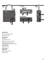
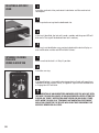
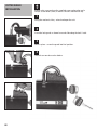
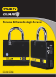
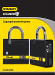
Access Control System
STST1-79226, STST320000
STST1-71238, STST321000
A
D
H
C
E
G
B
F
A) Lock - main unit
B) Key x2
C) User tag x4
D) Cutter shield (Note: not included in pack - see label)
E) Batteries x2
F) USB cable
G) User manual
H) Extended user manual (Disc)
Key In - Insert or remove mechanical key
Add new user / Pairing access control
Communication - USB & Bluetooth
(for ACS-BT) activation
Lock opened / remove users
Front
view
SIDE
view
TOP view
4
5
1
6
10
7
bottom view
11
2
8
9
3
FRONT VIEW
1) Shackle release button
2) Indication LEDs
3) Push button
TOP VIEW
4) Mechanical latch
5) Battery cover screw release
6) Electromechanical latch
7) Shackle protector screw thread
BOTTOM VIEW
8) Battery cover
9) User tag slot
SIDE VIEW
10) Key insertion slot
11) USB input
01
Thank you for choosing the Stanley Guard Access Control System.
• Keeping your valuable equipment safe and accounted for is crucial.
• The NEW lock is the best way to Control Your Job Site.
• The lock is easily programmed to open up during set hours and only to the
authorized workers with user tags.
• The log registers the entries.
• the SOFTWARE AND MOBILE APPLICATION ENABleS MANAGement of WORKERS DETAILS
AND CONTROL of THE LOCK*.
SET UP AND INSTALLATION
1. Please copy and keep the code marked on the key.
2. If the key is lost, contact customer service to order a new one. You will need to provide the code.
3. There is a spare key so you can also duplicate the key.
4. If there is no key and no code - the cylinder must be replaced.
Please contact Customer Service to send your lock to be fixed or deliver it in person.
INSTALLING THE
BATTERY
1
2
Insert the mechanical key and
Open the screw beneath the latch
rotate it clockwise until the lock opens. (4mm flat screw driver).
3
4
5
Place the battery cover back on
and close the screw tightly in a
clockwise direction.
6
Remove the battery cover.
02
Insert CR123A batteries. Make sure
that battery (-) is facing the springs.
The lock is ready for operation.
* Software not included/ Mobile application included with the ACS BT
ADDING NEWTHE
INSTALLING
USERS
BATTERY
(TAGS)
1
Insert the mechanical key and rotate
it counter-clockwise to "Pairing /
Access Control" position.
2
Insert a new user tag. After
successful pairing1 the green LED
will blink and the buzzer will sound
a melody. The new user has been
added to the system.
Note: You can enter up to 100 user tags, if you exceed this number the new user tag will not be paired
and the red led will blink 3 times together with buzzer “error” notification .
DELETING
ALL AUTHORIZED users
1
Insert the mechanical key and rotate it clockwise until the mechanical
latch opens.
2
Press and hold the push button until you hear a beeping sound.
3
The lock will generate repeated “warning” notification. The buzzer beeps
periodically and the red LED blinks accordingly.
4
If no change in the key position is made during the “Warning” period all
paired users will be deleted.
Note: You can abort this operation by changing THE key position
to “Key In” during the “Warning” notification.
Note: When the lock is in “TEMPORARY AUTHORIZATION FREEZE MODE”
(see page 5) users cannot be deleted, if you attempt to perform this
operation, the red LED will blink twice for notification purposes.
1
Pairing - adding of a new tag to the lock.
03
DELETING A SPECIFIC
USER
1
Insert the mechanical key and rotate it clockwise until the mechanical
latch opens.
2
Insert a paired user tag into the dedicated slot.
3
If the tag is identified, the lock will sound a melody and the green LED will
blink once. The tag will be deleted from lock’s memory.
4
If the tag is not identified or was previously deleted, the lock will play an
error notification and the red LED will blink 3 times.
OPENing / closing
the LOCK
USING a USER TAG
1
Make sure that the lock is in "Key In" position.
2
Insert the user tag.
3
If an identified tag is inserted the electromechanical latch will open/close
(depending on the previous state), an approval signal will be sounded and
a single green LED will blink.
Note: Insertion of an Unidentified/ Unpaired user tag will not open
the lock. The lock will advise of an unauthorized access attempt by
playing an “Error” notification and the red LED will blink 3 times.
Note: When the lock is in “TEMPORARY AUTHORIZATION FREEZE MODE”
and a tag is inserted, the Red LED will blink twice indicating that
access is denied for all users.
04
TEMPORARY
AUTHORIZATION FREEZE
Using this option the lock
will be opened/closed only by
using a mechanical key.
This will prevent other users
from accessing the lock unit.
1
Insert the mechanical key and rotate it counter-clockwise to the "Pairing /
Access Control" position.
2
Hold the push button on the front panel pressed until a buzzing sound is
heard and the red LED blinks.
3
The electromechanical latch will close (if open).
For ACS-BT only
Note: If the “Temporary Authorization Freeze Mode” was set using
the smart phone app this operation will override the automatic
settings (see the smart phone application manual/help).
Note: This mode allows all operations except opening/closing the
lock using user tags and deleting all authorized user tags (see
“DELETING ALL AUTHORIZED USERS”).
RELEASing the
AUTHORIZATION FREEZE
This operation will release the lock from "FREEZE" mode.
1
Insert the mechanical key and rotate it counter-clockwise to the "Pairing /
Access Control" position.
2
Hold the push button on the front panel pressed until a buzzing sound
heard and the green LED blinks.
3
The system is now back in full operational mode.
For ACS-BT only
Note: If the “Temporary Authorization Freeze Mode” was set using
the smart phone app this operation will override the automatic
settings (see the smart phone application manual/help).
05
PC CONNECTION
Connect the lock to the PC using a USB cable in order to download
and upload the history log and authorizations.
1
Insert the mechanical key and rotate it counter-clockwise to the
“COMMUNICATION” position.
2
Connect the lock to the PC using the mini USB cable.
3
Open the PC software (Not included in the pack).
For ACS-BT only
Note: If you were PREVIOUSLY connected via Bluetooth, connecting
to the PC will terminate Bluetooth communication.
Warning: Do not change the key position during data transfer this may cause data loss.
bluetooth
CONNECTION
STST1-79226
STST320000
Connect the lock to a smart phone via Bluetooth to manage users
and lock settings (details in the smart phone app help).
NOTE: the BLUETOOTH PAIRING CODE IS 1234
1
Insert the mechanical key and rotate it counter-clockwise to the
“COMMUNICATION” position.
2
Hold the push button pressed until buzzing sound is heard and the green
LED blinks - this operation will activate Bluetooth.
When Bluetooth is active green LED will start blinking.
3
Open the Smart phone app and connect to the lock (details in Smart phone
app user help).
06
4
To disconnect the Bluetooth change the key position (any position other
than the “COMMUNICATION” position).
Note: You can not activate Bluetooth when connected to PC via a
USB. connecting to a PC will terminate the Bluetooth connection.
Note: Bluetooth will shut down automatically when there is
no connection established for 5 minute (to save battery power),
you can activate Bluetooth again by pressing the push button in
“COMMunication” mode.
Note: Bluetooth communication will function in a range that is
no greater than 15 meters.
Warning: Do not change the key position during data transfer this may cause data loss.
LOW BATTERY
INDICATION
replacing the battery
REMOVING/CHANGING
the SHACKLE
When the lock's battery is low the red LED will start blinking, once every
10 seconds. The user should replace the batteries with new CR123A batteries. See page 2 of this guide - Installing the battery.
1
2
Insert the mechanical key and rotate it Press the shackle release button and
clockwise until the lock opens.
remove the shackle.
Rotate the shackle at a 90 degree angle.
3
4
Insert the new shackle in the same
manner.
07
CUTTER shield
INSTALLATION
Please make sure you have the supplied screw and washer and a
Phillips screw driver (2mm) as well as the units mechanical key.
1
Using the mechanical key - unlock and open the unit.
2
Insert the lock guard as shown here and slide along the lock's latch.
3
Once in place - screw the guard into final position.
4
The unit can now be used as before.
08
ACS specs
Standards
EN 609050-1
EN 609050-22
UL 60950-1
CSA CS22.2 60950-1
EN 301489
EN 300330
AS/NZS CISPR 22
VCCI V-3
FCC Part 15, Sub-Part B, C
FCC ID:RLBACS320000
FCC ID:RLBACS321000
Application High security electronic lock for access control.
Dimensions 105 x 150 x 37 mm
Weight 1550 gr including batteries
Keys Mechanical + Passive RFID
Standards BS EN 12320
Battery Type CR123A X 2
Nominal Operation voltage 6V
Battery Life Cycle Up to 6 months
Battery Capacity 1700 mAH
IP 55
Maximum Users 100
Communication Interface USB 2.0, Bluetooth (optional)
Max Bluetooth range 15m
Log Registration of time and events (Unlock, Lock, Pairing,
Delete,Authorizations freeze/unfreeze)
Log Capacity 1000 records
RFID Reader Frequency 125KHz
Operating temperature (-20) - (+60) ˚C
Storage temperature (-30) - (+85) ˚C
FCC ID RLBACS320000; RLBACS321000 (ACS-BT)
Patent Application Number US 13/166153 US 13/556234 EP 12172072.6
NOTE: In order to review a list of supported smartphones (for ACS-BT),
refer to the Android play market or Apple store.
This device complies with Part 15 of the FCC Rules.
Operation is subject to the following two conditions:
(1) This device may not cause harmful interference, and (2) this device must accept any interference received,
including interference that may cause undesired operation.
ACS IS NOT RESPONDING TO MECHANICAL KEY ROTATION AND
INSERTION OF USER TAGS
If the lock is still not responding make sure that batteries are installed
properly (check batteries polarity).
Still not working? Replace the batteries.
RED LED IS BLINKING EVERY 10 SECONDS This is a low battery indication.
Please replace the batteries.
LOCK DOES NOT CLOSE PROPERLY WHEN INSERTING THE USER TAG
If this occurs, it means that something is interfering with the electromechanical latch movement.
Insert the user tag again to open the lock.
Place the shackle properly in its place to allow latch movement.
Insert the user tag again to close the latch.
Note: When the electromechanical latch is not closed properly an “Error” notification will be sounded.
LOST YOUR USER TAGS
It is possible to erase tags from ACS database. Refer to the “DELETING A SPECIFIC USER” section of the user
manual. It is also possible to erase specific tags using the “Stanley Guard PC management software” or smart
phone application (Bluetooth version).
LOCK WAS LEFT OPEN, AND THE MASTER USER DOESN'T HAVE HIS USER TAG
Option 1 - Rotate the key to the “pairing position” and then to the “Key In” position. These operations will open a 10
seconds time window. During this period of time press the push button until the electromechanical latch is closed.
Option 2- The electromechanical latch is closed automatically when the master user places the lock in
TEMPORARY AUTHORIZATIONS FREEZE mode. Refer to this section in the user manual.
PC USB CONNECTION IS NOT ESTABLISHED
Make sure that the mechanical key position is in “COMMUNICATION” mode (refer to PC CONNECTION section).
Make sure that the USB cable is not corrupted or damaged.
trouble-shooting
& tips
09
BLUETOOTH CONNECTION IS NOT ESTABLISHED
Make sure that the key position is in “COMMUNICATION” mode.
Make sure that Bluetooth is activated - green LED is blinking.
To establish a connection stand at a distance of no more than 10 meters from the lock.
WHEN ADDING A NEW USER, ACS GENERATES AN ERROR INDICATION
Make sure that the user tag is not damaged or corrupted.
ACS can store up to 100 user tags. Trying to add more than 100 tags will cause ACS to generate an error indication.
LOCK INTERPRETS THE KEY POSITION INCORRECTLY
Rotate the key counter-clockwise to “COMMUNICATION” position and then rotate it clockwise until the mechanical
latch opens.
BATTERY OPERATION TIME
The battery's average operating time is approximately 6 months, however this may vary according to the usage
policy and environmental temperature.
MECHANICAL KEYS ARE LOST
Make sure you have copied the code marked on the key (the code of the key also appears on the last page of the
short manual). Contact Customer Service to order a new one. You will need to provide the code.
There is a spare key so you can also duplicate the key.
If there is no key and no code - the cylinder must be replaced. Please contact Customer Service and send your
lock to be fixed or deliever it in person.
WARNING : Read and understand all instructions.
Failure to follow all the instructions may result in electric shock, fire,
property damage and/or serious personal injury or death.
WARNING : SERIOUS INJURY OR DEATH.
This product was designed to provide protection for property only. Do not
use this product to provide bodily protectionand protection against fire.
Any use other than that suggested in this instruction manual may cause injury or even death.
WARNING : SERIOUS INJURY OR DEATH.
Do not use this product in hazardous areas. This includes blasting areas and potentially explosive atmospheres.
Sparks in such areas may cause an explosion or fire resulting in bodily injury or even death. They include but are
not limited to fueling areas such as gas stations; fuel or chemical transfer or storage facilities;
vehicles using liquefied petroleum gas (such as propane or butane); areas where the air contains chemicals or
particles, such as grain, dust, or metal powders; and any other area where one would normally be advised to turn
off a vehicle engine.
WARNING : SERIOUS INJURY OR DEATH. Consult with manufacturers of any medical devices, such as
pacemakers, hearing aids, etc., to determine if they are susceptible to interference from cellular devices.
WARNING : FIRE, ELECTRIC SHOCK OR ELECTROCUTION.
Connect only amini USB certified cable to the ACS USB jack. Connect the other side of the USB cable only to a
USB certified Host device such as PC or laptop.
Any use other cable may cause the device to malfunction or even injury or death caused by Fire or electric shock.
WARNING : DEVICE MALFUNCTION
Do not connect the ACS to a USB host device such as PC or laptop when the batteries are disconnected, this may
cause a device malfunction.
Do not use a damaged or corrupted USB cable, this may cause an unstable or bad connection with the device.
WARNING : DEVICE MALFUNCTION INJURY OR DEATH
Use only CR123A batteries for the device. Any other battery type may cause device malfunction or even injury or
death caused by fire or electrical shock.
Install the batteries correctly as specified in this manual. Improper installation may cause device malfunction.
INTERNAL LITHIUM ION BATTERY
WARNING : BATTERIES – EXPLOSION, INJURY OR FIRE.
The ACS contains a Lithium- Ion batteries. Carefully follow all of the instructions in this manual.
Never dispose of the ACS or its battery in a fire. Return to a Stanley service center to recycle the unit.
The battery can explode in a fire. Toxic fumes, Hydrogen and materials are produced when Lead Acid batteries are burned.
Lithium-Ion batteries can cause severe ACID burns.
general safety
rules
10
Do not disassemble, open, crush, bend, shred, puncture or deform the ACS and its battery.
If battery contents come into contact with the skin, immediately wash the area with a mild soap and water. If
the battery liquid comes into contact with the eye, rinse the open eye with water for 15 minutes or until irritation
ceases. In any case seek medical attention.
WARNING: To comply with FCC RF exposure compliance requirements, the device should be located at a distance
of at least 20 cm from people during normal operation. The antennas used for this product must not be co-located
or operated in conjunction with any other antenna or transmitter.
IMPORTANT NOTICES
This product is not user serviceable. There are no user serviceable parts inside the product. Servicing at a
STANLEY authorized service center is required to avoid damage to static sensitive internal components.
Unauthorized service will void the warranty.
Clean only with a dry cloth.
PRODUCT LIMITATIONS
An intruder may gain access through unprotected openings. An intruder with criminal intent, technical knowledge, or
jamming devices, may bypass the locking system.
This product will not operate without power. The equipment has an non rechargeable batteries. If the battery charge level
is low or they are not installed, the product will not operate.
Despite advanced design and regular testing, this equipment, like other electrical devices, is subject to component failure.
When you wish to close the lock using a user tag, make sure that the shackle is in its proper place to allow the
latch to close properly. It is your responsibility to ensure that the lock is closed properly.
FCC STATEMENT:
This equipment has been tested and found to comply with the limits for a class B digital device, pursuant to Part
15 of the FCC rules. These limits are designed to provide reasonable protection against harmful interference in a
residential installation.
This equipment generates, uses and can radiate radio frequency energy and, if not installed and used in
accordance with the instructions, may cause harmful interference to radio communications. However, there is
no guarantee that interference will not occur in a particular installation. If this equipment does cause harmful
interference to radio or television reception, which can be determined by turning the equipment off and on, the
user is encouraged to try to correct the interference by one or more of the following measures:
a) Reorient or relocate the receiving antenna.
b) Increase the separation between the equipment and receiver.
c) Connect the equipment to an outlet on a circuit different from that to which the
receiver is connected.
d) Consult the dealer or an experienced radio/TV technician.
This device complies with Part 15 of the FCC Rules.
Operation is subject to the following two conditions:
a) This device may not cause harmful interference
b) This device must accept any interference received, including interference that may cause undesired operation.
FCC Warning
Modifications not expressly approved by the manufacturer could void the user authority to operate the equipment
under FCC Rules.
11
LIMITED ONE YEAR
WARRANTY
This warranty covers manufacturing defects in materials or workmanship of your new Stanley Guard Access
Control System.
This warranty lasts for a period of one (1) year from the date of original purchase and is only available to the
original purchaser.
Stanley will, at its discretion, repair or replace any malfunctioning electromechanical system part of your new
Stanley Guard Access Control System.
In order to obtain warranty service, you must contact Stanley customer service in your country within one (1)
year of the date of original purchase. A customer service representative will assist you with warranty service
in accordance with this warranty. You must also provide a copy of the original purchase receipt, your name and
address, as well as a short written description of the product’s defect.
Service centers contact information is listed.
This warranty does not cover any problem with the electromechanical system relating to batteries, misuse, abuse,
normal wear and tear, failure to maintain, or an act of nature. This warranty does not cover any other aspect or
portion of your Stanley Guard Access Control System. Also, this warranty does not cover, and Stanley is not liable
for, the loss or damage of any of your property.
By purchasing the Stanley Guard Access Control System and accepting this warranty, the purchaser acknowledges
that Stanley is not an insurer of any property and that insurance products are available to the purchaser from other
sources to cover such losses.
This warranty does not cover and expressly disclaims all implied warranties of any nature, including implied
warranties of merchantability or fitness for a particular purpose.
Consequential and incidental damages are not recoverable under this warranty. Some states do not allow
limitations on implied warranties or on consequential or incidental damages, so the above exclusion may not apply
to you. This warranty gives you specific rights, and you may also have other rights which vary from state to state.
12
U.S and Canada
1000 Stanley Drive, Concord, NC 28027
Tel: 1-800-262-2161
[email protected]
www.stanleytools.com
Belgique et Luxemburg België en Luxembourg
E. Walschaertstraat 14-16 2800 Mechelen Belgium
NL Tel: +32 15 47 37 63 Fax: +32 15 47 37 99
FR Tel: +32 15 47 37 64 Fax: +32 15 47 37 99
[email protected]
www.stanleytools.eu
Denmark
Farverland 1B 2600 Glostrup
Tlf: 70201510 Fax: 70224910
www.stanleyworks.dk
Deutschland
Richard Klinger Str. 11 65510 Idstein
Tel: 06126-21-1 Fax: 06126-21-2770
www.stanleyworks.de
Ελλάς
Στράβωνος 7 & Βουλιαγμένης 159 Γλυφάδα 1
6674, Αθήνα
Τηλ: +30 210 8981-616 Φαξ: +30 210 8983-285
www.stanleyworks.gr
España
Parque de Negocios “Mas Blau” Edificio Muntadas,
c/Bergadá, 1, Of. A6 08820 El Prat de Llobregat (Barcelona)
Tel: 934 797 400 Fax: 934 797 419
[email protected]
www.stanleyworks.es
France
5, allée des hêtres BP 30084, 69579 Limonest Cedex
Tel: 04 72 20 39 20 Fax: 04 72 20 39 00
[email protected]
www.stanleyoutillage.fr
Schweiz Suisse
In der Luberzen 40 8902 Urdorf
Tel: 01 - 730 67 47 Fax: 01 - 730 70 67
www.stanleyworks.de
Ireland
210 Bath Road; Slough, Berks SL1 3YD UK
Tel: +44 (0)1753 511234 Fax: +44 (0)1753 572112
www.stanleytools.co.uk
Italia
SWK Utensilerie Srl
Energy Park – Building 03 Sud, Via Monza, 7/A
20871 Vimercate (MB)
Tel. 031.780304 – Fax 031.781766
www.stanley.it
Nederlands
Joulehof 12 4600 AB Bergen Op Zoom
Tel: +31 164 28 30 63 Fax: +31 164 28 32 00
[email protected]
Norge
Postboks 4613, Nydalen 0405 Oslo
Tel: 45 25 13 00 Fax: 45 25 08 00
Österreich
Werkzeug Vertriebsges m.b.H
Oberlaaerstrasse 248 A-1230 Wien
Tel: 01-66116-0 Fax: 01-66116-14
www.stanleyworks.de
Portugal
Centro de Escritórios de Sintra Avenida Almirante
Gago Coutinho, 132/134, Edifício 142710-418
Sintra 2710-418 Lisboa
Tel: 214 66 75 00 Fax: 214 66 75 75
[email protected]
Suomi
Tekniikantie 12 02150 Espoo
Puh: 010 400 430 Faksi: 0800 411 340
www.stanleyworks.fi
Sverige
Box 94 431 22 Mölndal
Tel: 031 68 61 00 Fax: 031 68 60 08
Türkiye
KALE Hırdavat ve Makina A.Ş. Defterdar Mah.
Savaklar Cad. No:15
Edirnekapı / Eyüp / İSTANBUL 34050
Tel: 0212 533 52 55 Faks: 0212 533 10 05
United Kingdom
210 Bath Road; Slough, Berks SL1 3YD
Tel: +44 (0)1753 511234 Fax: +44 (0)1753 572112
www.stanleytools.co.uk
Middle East & Africa P.O.Box - 17164, Jebel Ali (South Zone), Dubai,
UAE
Tel: +971 4 8127400 Fax: +971-4-8127036
www.stanleyworks.ae
Czech Republic
Stanley Black and Decker Czech Republic
s.r.o. Türkova 5b, 149 00, Prague, CZ Czech
Republic
Tel: +420 261 009 779 Fax: +420 261 009 770 Hungary
Stanley Black & Decker Hungary Ltd.
1016 Budapest, Meszaros u. 58/B Hungary
Tel: +36 12 140561
Poland
STANLEY BLACK&DECKER Polska Sp. z o.o. ul.
Postepu 21D 02-676 Warszawa Poland
Tel: 48 22 464-2700 Fax: 48 22 464-2701
Slovakia
Stanley Black & Decker Slovakia s.r.o.
Stará Vajnorská 8 SK-83104 Bratislava, Slovakia
Tel: +421 2 446 38 121,3 Fax: +421 2 446 38 122
Romania
STANLEY BLACK & DECKER
Splaiul Independentei
319 Corp Cladire
Ob. 153-200A Sector 6 0060044 BUCURESTI RO
Tel: +40 21 30 00 755 Fax: +40 21 31 81 126
Bulgaria
EUROTOOLS LTD.
Andrei Liapchev str. 14 1756 Sofia, Bulgaria
Tel: 359-2-4219723 Fax: 359-2-4219723
Tashev Galving LTD 68 Kliment Ohridski BLVD
1756 Sofia, Bulgaria
Slovenia
G-M&M D.O.O. BRVACE 11, SI -1290,
GROSUPLJE
Tel. +386(0)17866 500 Fax +386(0)1 7861 205
www.stanleyguard.com
http://www.stanley.eu/ics
© 2013 Stanley Black & Decker. Egide Walschaertsstraat 14-16, 2800 Mechelen, Belgium. http://www.stanleytools.eu
13690_ENG 10/13
www.stanleytools.com © 2013 Stanley Tools. 701 East Joppa Road, Towson, Maryland 21286
U.S. & Canada Only / E.-U. et Canada seulement