1
®
OPERATOR'S MANUAI
21" Self-Propelled
Mower
Model 247.379790
Factory No. 12A-979L402
IMPORTANT:
READ SAFETY RULES AND INSTRUCTIONS
CAREFULLY
Warning:
This unit is equipped with an internal combustion engine and should not be used on or near any unimproved forestcovered, brush-covered or grass-covered land unless the engine's exhaust system is equipped with a spark arrester meeting
applicable local or state laws (if any). If a spark arrester is used, it should be maintained in effective working order by the operator.
In the State of California the above is required by law (Section 4442 of the California Public Resources Code). Other states may have
similar laws. Federal laws apply on federal lands. A spark arrester for the muffler is available through your nearest engine authorized
service dealer or contact the service department, P.O. Box 361131 Cleveland, Ohio 44136-0019.
MTD LLC, P.O. BOX 361131 CLEVELAND,
PRINTED IN U.S.A.
OHIO 44136-0019
FORM NO. 769-00049
(2/02)
TABLEOFCONTENTS
Content
Page
Important Safe Operation Practices ...................................................................
3
Slope Gauge ......................................................................................................
6
Assembling Your Lawn Mower ...........................................................................
7
Know Your Lawn Mower ....................................................................................
8
Operating Your Lawn Mower .............................................................................
9
Making Adjustments ..........................................................................................
11
Maintaining Your Lawn Mower ...........................................................................
12
Troubleshooting .................................................................................................
16
Parts List ............................................................................................................
18
FINDINGMODELNUMBER
This Operator's Manual is an important part of your new lawn mower. It will help you assemble, prepare and
maintain the unit for best performance. Please read and understand what it says.
Before you start assembling your new equipment, please locate the model plate on the
equipment and copy the information from it in the space provided below. The information on the
model plate is very important if you need help from our Customer Support Department or an
authorized dealer.
You can locate the model number by looking down at the rear of the deck. A sample model plate is
explained below. For future reference, please copy the model number and the serial number of the
equipment in the space below.
Copy the model number here:
Copy the serial number here:
ENGINEINFORMATION
The engine manufacturer is responsible for all engine-related issues with regards to performance, powerrating, specifications, warranty and service. Please refer to the engine manufacturer's Owner's/Operator's
Manual packed separately with your unit for more information.
CALLINGCUSTOMER
SUPPORT
If you have difficulty assembling this product or have any questions regarding the controls, operation or
maintenance of this unit, please call the Customer Support Department.
Call 1- (330) 220-4MTD (4683) or 1- (800)-800-7310 to reach a Customer Support
representative. Please have your unit's model number and serial number ready when you
call. See previous section to locate this information. You will be asked to enter the serial
number in order to process your call.
SECTION1' IMPORTANTSAFEOPERATIONPRACTICES
WARNING:
This symbol points out important safety instructions which, if not followed, could
endanger the personal safety and/or property of yourself and others. Read and follow all instructions in
this manual before attempting to operate this machine. Failure to comply with these instructions may
result in personal injury. When you see this symbol - heed its warning.
WARNING:
Engine Exhaust,
some of its constituents,
and certain vehicle
components contain or emit chemicals known to State of California
and birth defects or other reproductive harm.
DANGER:
to cause cancer
This machine was built to be operated according to the rules for safe operation in this
manual. As with any type of power equipment, carelessness or error on the part of the operator can
result in serious injury. This machine is capable of amputating hands and feet and throwing objects.
Failure to observe the following safety instructions could result in serious injury or death.
GeneralOperation
1.
2.
3.
4.
5.
6.
7.
Read this operator's manual carefully in its entirety
before attempting to assemble this machine. Read,
understand, and follow all instructions on the machine
and in the manual(s) before operation. Be completely
familiar with the controls and the proper use of this
machine before operating it. Keep this manual in a safe
place for future and regular reference and for ordering
replacement parts.
This machine is a precision piece of power equipment,
not a plaything. Therefore, exercise extreme caution at all
times. Your unit has been designed to perform one job: to
mow grass. Do not use it for any other purpose.
Never allow children under 14 years old to operate this
machine. Children 14 years old and over should read and
understand the operation instructions and safety rules in
this manual and should be trained and supervised by a
parent. Only responsible individuals who are familiar with
these rules of safe operation should be allowed to use
this machine.
Thoroughly inspect the area where the equipment is to
be used. Remove all stones, sticks, wire, bones, toys and
other foreign objects which could be tripped over or
picked up and thrown by the blade. Thrown objects can
cause serious personal injury. Plan your mowing pattern
to avoid discharge of material toward roads, sidewalks,
bystanders and the like. Also, avoid discharging material
against a wall or obstruction which may cause
discharged material to ricochet back toward the operator.
To help avoid blade contact or a thrown object injury, stay
in the operator zone behind the handles and keep
children, bystanders, helpers and pets at least 75 feet
from the mower while it is in operation. Stop machine if
anyone enters the area.
Always wear safety glasses or safety goggles during
operation and while performing an adjustment or repair to
protect your eyes. Thrown objects which ricochet can
cause serious injury to the eyes.
Wear sturdy, rough-soled work shoes and close-fitting
slacks and shirts. Shirts and pants that cover the arms
and legs and steel-toed shoes are recommended. Never
operate this machine in bare feet, sandals, slippery or
light weight (e.g. canvas) shoes.
8.
9.
10.
11.
12.
13.
14.
15.
16.
17.
18.
19.
Do not put hands or feet near rotating parts or under the
cutting deck. Contact with the blade can amputate hands
and feet.
A missing or damaged discharge cover can cause blade
contact or thrown object injuries.
Many injuries occur as a result of the mower being pulled
over the foot during a fall caused by slipping or tripping.
Do not hold on to the mower if you are falling; release the
handle immediately.
Never pull the mower back toward you while you are
walking. If you must back the mower away from a wall or
obstruction first look down and behind to avoid tripping
and then follow these steps:
a. Step back from the mower to fully extend your
arms.
b. Be sure you are well balanced with sure footing.
c. Pull the mower back slowly, no more than half way
toward you.
d. Repeat these steps as needed.
Do not operate the mower while under the influence of
alcohol or drugs.
Do not engage the self-propelled mechanism on units so
equipped while starting engine.
The blade control handle is a safety device. Never
attempt to bypass its operation. Doing so makes the
safety device inoperative and may result in personal
injury through contact with the rotating blade. The blade
control handle must operate easily in both directions and
automatically return to the disengaged position when
released.
Never operate the mower in wet grass. Always be sure of
your footing. A slip and fall can cause serious personal
injury. If you feel you are losing your footing, release the
blade control handle immediately and the blade will stop
rotating within three seconds.
Mow only in daylight or in good artificial light. Walk, never
run.
Stop the blade when crossing gravel drives, walks or
roads.
If the equipment should start to vibrate abnormally, stop
the engine and check immediately for the cause.
Vibration is generally a warning of trouble.
Shut the engine off and wait until the blade comes to a
complete stop before removing the grass catcher or
unclogging
thechute.
Thecuttingblade
continues
to
obscure your vision of a child who may run into the
mower.
rotateforafewseconds
aftertheengine
isshutoff.Never
placeanypartofthebodyinthebladeareauntilyouare
Keep children away from hot or running engines. They
can suffer burns from a hot muffler.
surethebladehasstopped
rotating.
6.
20. Never
operate
mower
without
proper
trailshield,
Never allow children under 14 years old to operate a
discharge
cover,grasscatcher,
bladecontrol
handle
or
power mower. Children 14 years old and over should
othersafetyprotective
devices
inplaceandworking.
read and understand the operation instructions and
Never
operate
mower
withdamaged
safety
devices.
safety rules in this manual and should be trained and
Failure
todoso,canresultinpersonal
injury.
supervised by a parent.
21. Muffler
andengine
become
hotandcancause
aburn.Do
nottouch.
Service
22. Onlyusepartsandaccessories
made
forthismachine
by
themanufacturer.
Failure
todoso,canresultinpersonal Safe Handling Of Gasoline:
injury.
1. To avoid personal injury or property damage use extreme
23. Ifsituations
occurwhicharenotcovered
inthismanual,
care in handling gasoline. Gasoline is extremely
usecareandgoodjudgment.
Contact
yourdealer
for
flammable and the vapors are explosive. Serious
assistance.
Telephone
1-800-800-7310
forthenameof
personal injury can occur when gasoline is spilled on
yournearest
dealer.
yourself or your clothes which can ignite.
5.
SlopeOperation
Slopes are a major factor related to slip and fall accidents
which can result in severe injury. Operation on slopes
requires extra caution. If you feel uneasy on a slope, do not
mow it. For your safety, use the slope gauge included as part
of this manual to measure slopes before operating this unit on
a sloped or hilly area. If the slope is greater than 15 degrees,
do not mow it.
Do:
1. Mow across the face of slopes; never up and down.
2.
3.
Exercise extreme caution when changing direction on
slopes.
Watch for holes, ruts, rocks, hidden objects, or bumps
which can cause you to slip or trip. Tall grass can hide
obstacles.
Always be sure of your footing. A slip and fall can cause
serious personal injury. If you feel you are losing your
balance, release the blade control handle immediately,
and the blade will stop rotating within 3 seconds.
2.
3.
4.
5.
6.
7.
8.
9.
10.
DO Not:
1.
2.
3.
Do not mow near drop-offs, ditches or embankments, you
could lose your footing or balance.
Do not mow slopes greater than 15 degrees as shown on
the slope gauge.
Do not mow on wet grass. Unstable footing could cause
slipping.
11.
12.
13.
Children
14.
Wash your skin and change clothes immediately.
Use only an approved gasoline container.
Never fill containers inside a vehicle or on a truck or
trailer bed with a plastic liner. Always place containers on
the ground away from your vehicle before filling.
When practical, remove gas-powered equipment from
the truck or trailer and refuel it on the ground. If this is not
possible, then refuel such equipment on a trailer with a
portable container, rather than from a gasoline dispenser
nozzle.
Keep the nozzle in contact with the rim of the fuel tank or
container opening at all times until fueling is complete. Do
not use a nozzle lock-open device.
Extinguish all cigarettes, cigars, pipes and other sources
of ignition.
Never fuel machine indoors because flammable vapors
will accumulate in the area.
Never remove gas cap or add fuel while the engine is hot
or running. Allow engine to cool at least two minutes
before refueling.
Never over fill fuel tank. Fill tank to no more than ½ inch
below bottom of filler neck to provide space for fuel
expansion.
Replace gasoline cap and tighten securely.
If gasoline is spilled, wipe it off the engine and equipment.
Move unit to another area. Wait 5 minutes before starting
the engine.
Never store the machine or fuel container inside where
there is an open flame, spark or pilot light as on a water
heater, space heater, furnace ,clothes dryer or other gas
appliances.
To reduce fire hazard, keep mower free of grass, leaves,
or other debris build-up. Clean up oil or fuel spillage and
remove any fuel soaked debris.
Allow a mower to cool at least 5 minutes before storing.
Tragic accidents can occur if the operator is not alert to the
presence of children. Children are often attracted to the
mower and the mowing activity. They do not understand the
dangers. Never assume that children will remain where you
last saw them.
General Service:
1.
1.
2.
3.
4.
Keep children out of the mowing area and under the
watchful care of a responsible adult other than the
operator.
Be alert and turn mower off if a child enters the area.
Before and while moving backwards, look behind and
down for small children.
Use extreme care when approaching blind corners,
doorways, shrubs, trees, or other objects that may
15.
2.
Never run an engine indoors or in a poorly ventilated
area. Engine exhaust contains carbon monoxide, an
odorless and deadly gas.
Before cleaning, repairing, or inspecting, make certain
the blade and all moving parts have stopped. Disconnect
the spark plug wire and ground against the engine to
prevent unintended starting.
3. Check
thebladeandengine
mounting
boltsatfrequent
intervals
forproper
tightness.
Also,visually
inspect
blade
fordamage
(e.g.,bent,cracked,
worn)Replace
blade
withtheoriginal
equipment
manufacture's
(O.E.M.)
blade
only,listedinthismanual.
"Useofpartswhichdonot
meettheoriginal
equipment
specifications
mayleadto
improper
performance
andcompromise
safety!"
4. Mower
blades
aresharpandcancut.Wrapthebladeor
weargloves,
anduseextracaution
whenservicing
them.
5. Keepallnuts,bolts,andscrews
tighttobesurethe
equipment
isinsafeworking
condition.
6. Never
tamper
withsafetydevices.
Check
theirproper
operation
regularly.
7. Afterstriking
aforeign
object,
stoptheengine,
disconnect
thesparkplugwireandground
against
theengine.
Thoroughly
inspect
themower
foranydamage.
Repair
thedamage
before
starting
andoperating
themower.
8. Never
attempt
tomakeawheelorcutting
height
adjustment
whiletheengine
isrunning.
_
9. Grass
catcher
components,
discharge
cover,andtrail
shieldaresubject
towearanddamage
whichcould
expose
moving
partsorallowobjects
tobethrown.
For
safetyprotection,
frequently
check
components
and
replace
immediately
withoriginal
equipment
manufacturer's
(O.E.M.)
partsonly,listedinthismanual.
"Useofpartswhichdonotmeettheoriginal
equipment
specifications
mayleadtoimproper
performance
and
compromise
safety!"
10. Donotchange
theengine
governor
setting
oroverspeed
theengine.
Thegovernor
controls
themaximum
safe
operating
speedoftheengine.
11. Maintain
orreplace
safety
andinstruction
labels,
as
necessary.
12. Observe
proper
disposal
lawsandregulations.
Improper
disposal
offluidsandmaterials
canharmthe
environment.
understand
the warnings
and instructions in Restrict
this manual
and ofonthis
the power
machine.
ARNINGand -follow
YOUR
RESPONSIBILITY:
the use
machine to persons who read,
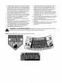
NOTE: Not all safety labels shown may apply to your lawn mower.
o
E
SIGHT AND HOLD THIS LEVEL WITH A VERTICAL TREE
i"11
t-
O
>,
I
o
o
C
o
{3.
O
O
t>,
E
_3
o
>,
t-
{3.
o
15 °
<
"E
o
._J
t,,/3
=
O3
z
O30.
O
b
_
,_WARNING
Do not mow on inclines with a slope in excess of 15 degrees (a rise of approximately 2-1/2 feet every 10 feet). A riding mower could
overturn and cause serious injury. If operating a walk-behind mower on such a slope, it is extremely difficult to maintain your footing
and you could slip, resulting in serious injury.
Operate RIDING mowers up and down slopes, never across the face of slopes.
Operate WALK-BEHIND mowers across the face of slopes, never up and down slopes.
SECTION3' ASSEMBLINGYOURLAWN MOWER
IMPORTANT: This unit is shipped without gasoline or oil
in the engine. Be certain to service engine with gasoline
and oil as instructed in the separate engine manual
before operating your mower.
Assembly
NOTE: Reference to right or left hand side of the mower
is observed from the operating position.
Wing N_Jt
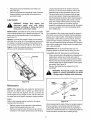
RemovingUnit FromCarton
•
Remove staples, break glue on top flaps, or cut
tape at carton end and peel along top flap to open
carton.
•
Remove loose parts if included with unit (i.e.,
operator's manual, oil, etc.)
Cut along corners, lay carton down flat, and remove
packing material.
Roll or slide unit out of carton and check carton
•
•
Handle Mountin
Bracket
Figure 2
•
thoroughly for loose parts.
LooseParts in Carton
•
•
•
•
Grass Bag
Grass Bag Adapter
Side Discharge Chute
Hardware Pack
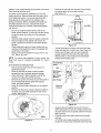
•
Remove the hairpin clips from the outer hole in the
weld pins on the handle mounting brackets. Using a
pair of pliers, squeeze one leg of the lower handle
against the handle mounting bracket. Insert the
hairpin clip into the inner hole on the weld pin.
Repeat on other side. See Figure 3.
After moving the hairpin clip, insert the carriage bolt
from hardware pack in the upper hole on the handle
mounting bracket and secure with plastic wing nut
from the hardware pack. Repeat on other side.
DisconnectingSpark PlugWire
•
Before setting up your lawn mower, disconnect the
spark plug wire from the spark plug and ground
against the engine. See Figure 1.
L°aW;;"
e_
wn0
_,¢t_---Carriage Bolt
Inner Hole
Bracket
lip
Spark
Wire
Spark
Handle Moun "
Hairpin
Figure 3
Figure 1
Setting UpYour Lawn Mower
•
•
Remove grass bag and other loose parts from unit
and set it aside.
Lift up and pull back on the upper handle to raise
the handle into the operating position. Make
certain the lower handle is seated securely into the
handle mounting brackets. Tighten the wing nuts
on each side of the handle (carriage bolts must be
seated properly into the handle). See Figure 2.
NOTE: Your mower is shipped with the handle in the
higher height position. If you wish to lower the height of
the handle, refer to the Adjustment Section at this time.
Fasten the cables to the lower handle with the two
cable ties found on the lower handle. Be sure to
insert the post on the cable ties into the holes
provided on the lower handle. These holes may be
found on either the inside or outside of the handles.
Pull the cable ties tight and trim offthe excess.
See Figure 4.
Cable Tie,
Lower
Handle
Figure 4
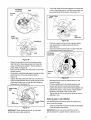
NOTE: Make certain the drive cable is routed around
the outside and above the lower handle so it does not
Lower
interfere with attaching the grass bag.
The rope guide, which is connected to the support
rod, is located on the right side of lower handle.
See Figure 5.
With the spark plug wire disconnected and
grounded, hold the blade control handle against the
upper handle, and pull the starter rope out of the
engine. Release the blade control handle. Slip the
starter rope into the rope guide.
Rope
Ro
Guide
Figure 5
SECTION4: KNOWYOURLAWNMOWER
Read this operator's manual and safety rules before
operating your lawn mower. Compare the illustrations
in Figure 6 with your lawn mower to familiarize yourself
with the location of various controls and adjustments.
Save this manual for future reference.
WARNING: The operation of any lawn
mower can result in foreign objects being
thrown into the eyes, which can damage
your eyes severely. Always wear safety
glasses while operating the mower, or
while performing any adjustments
or
repairs on it.
Recoil Starter
The recoil starter is attached to the right lower handle.
Stand behind the unit and pull the recoil starter to start
the unit. See Figure 6.
Blade Control Handle
speed selection, release the drive clutch control. See
Figure 6.
NOTE: Move the shift lever only when the engine is
running. Changing the shift lever setting with the
engine off can cause damage to the mower.
Grass Bag
The grass bag is equipped with a bag-fill indicator to
add convenience to your work. While the mower is
running, air will flow through the bag and into the "sail."
If the grass catcher is empty, air flows through easily
pushing the sail up. If the grass catcher is full, air does
not flow through it allowing the sail to fall. So the
position of the sail acts as a bag-fill indicator signifying
when to empty the grass bag. See Figure 6.
Engine Controls
See the separate engine manual for the location and
function of the controls on the engine.
The blade control handle is located on the upper handle
of the mower. The blade control handle must be
depressed in order to operate the unit. Release blade
control handle to stop engine and blade. See Figure 6.
Blade Control
Handle
Lever
is a safety device. Never attempt to bypass
WARNING: This blade control mechanism
its operations.
Cutting Height AdJustment Lever
The cutting height adjustment lever is located above
the left rear wheel. To adjust the cutting height, refer to
the Adjustment Section in this manual. See Figure 6.
Drive Clutch Control
The drive clutch control is located on the upper handle.
Squeeze the drive control to engage the drive system.
Release the clutch control to disengage the drive
system. Release the clutch control to slow down when
approaching an obstacle, making a turn, or stopping.
See Figure 6.
Shift Lever
The shift lever is located on the drive clutch control
housing on the upper handle. This lever is used to
select the forward speed of the mower. When changing
Cutting Height
Adjustment Lever
Drive
Control
Mulching
Starter
Plug
Grass
Discharge
Chute.,_
Figure 6
SECTION5: OPERATING
YOURLAWNMOWER
TowardsBetter Mower Performance
1.
2.
3.
4.
Pour fresh, clean gasoline into the mower's gas
tank until the tank is full. Do not use gasoline
that is more than 30 days old.
Make sure to connect the mower's spark plug
wire before trying to start the engine.
5.
Hold control handle down and pull rope firmly to
start the engine.
6.
Set cutting height adjustment lever to middle
setting and mow a single pass on your lawn;
then adjust to desired height for a closer cut.
Add engine oil to the oil fill on the mower engine.
Check the dipstick and add more if necessary.
Remember that the oil level has to touch the fill
line.
7.
To mulch insert the mulch plug/cover on the
mower.
8.
Before storing the lawn mower for the winter,
use stabilizer-treated fuel and run the tank dry.
9.
Thirty days before start of the new season,
check the air filter, spark plug and blade on the
lawn mower, and replace if needed.
•
Squeeze the drive clutch control and pull the
mower backward. Do the rear wheels lock?
Is the drive clutch control cable free of kinks or
Locate the primer decal near the primer bulb on
the engine, and read its instruction. Using your
thumb, press the primer bulb slowly as many
times as the decal advises.
WARNING:
Keep hands and feet away
from chute area on the cutting deck. The
operation of any lawn mower can result in
foreign objects being thrown into the
eyes, which can result in severe eye
damage. Always wear safety glasses or
eye shields.
NOTE: For shipping purposes your mower is set with
the wheels in a low cutting height position. For best
results raise the cutting position until it is determine
which height is best for your lawn. See the adjustment
section for details.
•
•
•
Starting Engine
•
Gasand Oil Fill-Up
Service the engine with gasoline and oil as instructed in
the separate engine manual packed with your mower.
Read instructions carefully.
engine
running
the indoors
engine with
has
WARNING:
Never or
fill until
fuel tank
been allowed to cool for at least two
•
•
•
minutes after running.
BeforeStarting Your Mower
•
•
Attach spark plug wire to spark plug. Make certain
the metal cap on the end of the spark plug wire is
fastened securely over the metal tip on the spark
plug.
Check for proper drive clutch operation using the
NEUTRAL ADJUSTMENT TEST.
NeutralAdjustmentTest
sharp bends?
If you answered "yes" to all three questions, your
mower passed the test and you can start your
mower.
If you answered "no" to any of the three questions,
you will have to adjust the drive clutch control as
instructed in the ADJUSTMENT SECTION.
Prime engine as instructed in the separate engine
manual packed with your unit.
Your lawn mower is equipped with a constant
speed throttle, which is set at full throttle for best
performance.
Stand behind the mower and squeeze the blade
control handle against the upper handle.
Grasp recoil starter handle and pull rope out slowly
until engine reaches the start of compression cycle
(rope will pull slightly harder at this point). Let the
rope rewind slowly. Pull rope with a rapid,
continuous, full arm stroke. Keeping a firm grip on
the starter handle, let the rope return to the starter
slowly.
Stopping Engine
°
Release blade control handle to stop the engine
and the blade.
°
Disconnect spark plug wire and ground it to the
post on the engine.
To perform the neutral adjustment test answer the
following questions.
UsingYour Lawn Mower
•
Be sure that the lawn is clear of stones, sticks, wire, or
other objects which could damage the lawn mower or
With the drive clutch control released, push mower
forward and pull it backward. Does it move freely?
theengine.Suchobjectscouldbeaccidently
thrownby
themowerinanydirectionandcauseseriouspersonal
injurytotheoperatorandothers.
Forbestresults,donotcutwetgrassbecauseittends
tosticktotheunderside
ofthemower,preventing
properdischarge
ofgrassclippings,
andcouldcause
youtoslipandfall.Newgrass,thickgrass,orwetgrass
mayrequirea narrower
cut.
Fora healthierlawn,nevercutoffmorethanone-third
ofthetotallengthofthegrass.Yourlawnshouldbecut
inthefallaslongasthereis growth.Thismoweris
designedtobeoperatedatfullthrottletogiveyouthe
bestcutanddothemosteffectivejobofmowingor
mulching.
WARNING:If you strike a foreign object,
•
Replace with grass bag adapter, while making
sure the front lip of adapter goes under the edge of
the deck. Secure with wing nuts previously
removed.
•
Lift chute door on the grass bag adapter and slide
grass bag onto the adapter. See Figure 8.
NOTE: The chute door has been designed to move the
starter rope out of the way of the bag when the chute
door is opened.
Chute
stop the engine. Remove wire from the
spark plug, thoroughly inspect the mower
for any damage, and repair the damage
before
restarting
and operating
the
mower. Extensive vibration of the mower
during operation
is an indication
of
damage. The unit should be promptly
inspected and repaired.
Bag
Figure 8
Mulching
Attaching Side DischargeChute
For effective mulching, do not cut wet grass because it
tends to stick to the underside of the deck, preventing
proper mulching of grass clippings. New or thick grass
may require a narrower cut. The ground speed should
be adjusted to the condition of the lawn. If mowing has
been delayed and the grass has been allowed to grow
in excess of 4", mulching is not recommended. Mow
using the grass bag to reduce the grass height to 3 1/4"
maximum before mulching.
•
•
Remove mulching baffle or grass bag adapter from
unit by disconnecting wing nuts.
Attach side discharge chute to unit and secure with
the three wing nuts. See Figure 9.
Attaching The GrassBag
•
Remove three wing nuts holding the mulching
baffle or side discharge chute in place and remove
from unit. See Figure 7.
Grass Bag
Side Discharge
Chute
\
Figure 9
Emptyingthe GrassBag
•
•
Nuts
•
Figure 7
10
While holding the grass bag by both the rear handle
and the lower handle, lift the grass bag straight up
off the adapter. The chute door will move the rope
out of the way of the bag.
Continue to hold the lower handle and raise the
rear of the grass bag up toward your chest. The
grass bag will open and the grass clippings will
disperse.
When replacing the grass bag, be sure the top of
the bag rests on the wire support between the
handles.
SECTION6: MAKINGADJUSTMENTS
•
adjustments
without
engine
WARNING: Do
not atfirst
any stopping
time make
any
and disconnecting spark plug wire.
Cutting Height Adjustment
•
•
Your mower is shipped with the cutting height in the
lowest position. The cutting height adjustment lever is
located above the left rear wheel. To adjust the cutting
height, pull the lever out and away from the mower and
then move it forward or backward to select a new
Place the hairpin clips in the inner holes in the weld
pins and insert the carriage bolts the upper hole on
the handle mounting bracket and secure with
plastic wing nuts.
Reassemble the upper handle to the lower handle.
Attach the starter rope as instructed in the
Assembly Section.
cutting height. See Figure 10.
Notch
NOTE: For rough or uneven lawns, move the height
adjustment lever to a higher position. This will help stop
scalping.
Lower Handle
Cutting Height
Adjustment Lever
Figure 11
Drive ClutchControlAdjustment
The adjustment wheel is located in the drive clutch
control handle housing and is used to tighten or loosen
the drive belt. You will have to adjust the drive clutch
control if any of the following happens:
•
•
The mower does not propel itself with the drive
clutch engaged.
The mower's drive wheels hesitate with the drive
clutch engaged.
To resolve the above problems, rotate the adjustment
wheel with your fingers. Clockwise to tighten the cable
and counter-clockwise to loosen the cable.
Figure 10
See Figure 12.
HandleHeightAdjustment
Bottom View
Your mower is shipped with the handle in the higher
height position. To lower the height proceed as follows:
•
•
•
•
•
®
Remove the starter rope from the rope guide.
Remove the upper handle by removing the hand
knobs and carriage bolts. Lay the upper handle out
of the way, being careful not to bend or kink the
cables.
Remove the hairpin clips from the weld pins on the
handle brackets and remove the wing nuts and
carriage bolts from the upper hole on the handle
mounting bracket. Press out on the legs of the
lower handle and remove lower handle from the
mower.
Turn lower handle around so the notch on the
bottom of the lower handle is facing forward.
See Figure 11.
Reassemble, placing the bottom holes in the
handle over the weld pins in the handle mounting
bracket.
pper
Handle
Adjustment
Wheel_,_
D
Clutch
Control
Figure 12
NOTE: For some people the drive clutch control may
not be in a comfortable position. You can adjust the
handle out by tightening the adjustment wheel
Shift LeverCableAdjustment
Periodic adjustment of the six speed shift cable may be
11
required due to normal wear on the cable. Adjustment
is needed if all six speeds do not work.
•
The adjustable cable bracket is located on the left side
of the mower beside the engine. See Figure 14.
•
•
Loosen hex nut which secures the adjustable cable
bracket. See Figure 14.
Push back on the adjustable cable bracket and
tighten hex nut.
Adjustable
Bracket
Start engine and place speed control lever in the
sixth speed position. See Figure 13.
Cable
Hex Nut
Bottom View
®
Speed Control
Lever
Upper
Handle
PUSH
Figure 14
EngineAdjustments
Figure 13
See the separate engine manual packed with your unit
for adjustments to the engine.
Stop engine and disconnect spark plug wire and
ground it against engine.
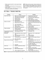
SECTION7' MAINTAININGYOURLAWNMOWER
GeneralRecommendations
CustomerResponsibilities
MAINTENANCE
SERVICE
SCHEDULE
DATES
Lubricate Wheels
O
Lubricate Blade Control
8
n_
n
Clean Deck
_
Blade Care
_
Check Oil
Change Oil
_
Replace Air Filter
ZLZ
9 Clean Engine
I.U
_
Check Spark Plug
q_
Check Spark Arrester (if any)
Always observe safety rules when performing any
maintenance.
°
The warranty on this lawn mower does not cover
items that have been subjected to operator abuse
or negligence. To receive full value from the
warranty, operator must maintain the lawn mower
as instructed in this manual.
°
12
Changing of engine governed speed will void
engine warranty.
Some adjustments will have to be made
periodically to maintain your unit properly. All
adjustments in the Making Adjustments section of
this manual should be checked at least once each
season.
Periodically check all fasteners and make sure
these are tight.
Follow the maintenance schedule under Customer
Responsibilities to get quality performance from
your lawn mower.
usually indicate that the air cleaner should be
serviced. To service the air cleaner, refer to the
separate engine manual packed with your unit.
The spark plug should be cleaned and the gap
reset once a season. Spark plug replacement is
recommended at the start of each mowing season.
Clean the engine regularly with a cloth or brush.
Keep the cooling system (blower housing area)
clean to permit proper air circulation which is
essential to engine performance and life. Be certain
to remove all grass, dirt, and combustible debris
from muffler area.
Lubrication
disconnect
spark
plug
wire
before
WARNING:
Always
stop engine
and
cleaning, lubricating or doing any kind of
service work on the lawn mower.
Deck
Blade Control: Lubricate the pivot points on the blade
control handle at least once a season with light oil. The
blade control must operate freely in both directions.
See Figure 15.
The underside of the mower deck should be cleaned
after each use to prevent a buildup of grass clippings,
leaves, dirt, or other matter. If this debris is allowed to
accumulate, it will invite rust and corrosion, and may
prevent proper mulching, discharge, or bagging. The
deck may be cleaned by tilting the mower and scraping
clean with a suitable tool (make certain the spark plug
wire is disconnected).
Wheels: Lubricate the wheels at least once a season
with light oil (or motor oil). If the wheels are removed for
any reason, lubricate the surface of the axle bolt and
inner surface of the wheel with light oil. See Figure 15.
Engine: Follow the separate engine manual packed
with you unit for lubrication instructions.
IMPORTANT:We do not recommend the use of a
pressure washer or garden hose to clean your unit.
Cutting Blade Removal, Replacement, and Sharpening
•
When removing the cutting blade for sharpening or
replacement, protect your hands with a pair of
heavy gloves or use a heavy rag to hold the blade.
•
Remove the bolt and the blade bell support which
hold the blade and the blade adapter to the engine
crankshaft. See Figure 16.
•
Remove the blade and the adapter from the
crankshaft.
Lubricate
adapter for cracks, especially if you strike
WARNING: Periodically inspect the blade
a foreign object. Replace when necessary.
Figure 15
Blade
Ada
Maintenance
Blade Bell
NOTE: When tipping the unit, empty the fuel tank and
keep the air cleaner side of engine up. Never tip the
mower more than 90 degrees and do not leave the
mower tipped for any length of time. Oil can drain into
the upper part of the engine causing a starting problem.
Bolt
Engine
Refer to the separate engine manual for all engine
maintenance instructions.
•
•
Figure 16
When sharpening the blade, follow the original angle of
grind as a guide. It is extremely important that each
cutting edge receives an equal amount of grinding to
prevent an unbalanced blade. An unbalanced blade will
cause excessive vibration when rotating at high
Maintain engine oil as instructed in the separate
engine manual packed with your unit.
Service air cleaner every 25 hours under normal
conditions. Poor engine performance and flooding
13
speeds. It may cause damage to the mower, and could
break causing personal injury.
Remove the hex bolt from the rear of unit holding
the transmission to the mower housing.
See Figure 18.
The blade can be tested by balancing it on a round
shaft screwdriver. Remove metal from the heavy side
until it balances evenly. It is recommended that the
blade always be removed from the adapter when
testing for balance. Before reinstalling the blade and
the blade adapter to the unit, lubricate the engine
crankshaft and the inner surface of the blade adapter
with light oil.
•
Be sure to install the blade with the side of the
•
•
•
•
/Hex
blade marked "Bottom" (or with part number) facing
the ground when the mower is in the operating
position.
Slide the blade adapter onto the engine crankshaft.
Place the blade on the adapter. Be certain the
blade is aligned and seated on the blade adapter
flanges.
Place blade bell support on blade. Make sure the
notches on the blade bell support are aligned with
small holes in the blade.
Figure 18
,
,
Replace hex bolt and tighten to torque: 450 in. Ibs.
min., 600 in. Ibs. max.
,
NOTE: To ensure safe operation of your mower, the
blade bolt must be checked periodically for correct
torque.
•
Tilt the transmission forward and loosen the idler
pulley bolt and lock nut halfa turn. See Figure 19.
Using a pair of pliers, pull back and rotate belt
keeper bracket from the slot on the idler pulley.
Slide the belt out from between the belt keeper
bracket and the idler pulley.
Transmission
Pulley
Drive Belt Removaland Replacement
•
Disconnect the spark plug wire and ground it
against the engine.
•
Drain the fuel tank or place a piece of plastic
beneath the cap to prevent gasoline leakage.
•
Place shift lever in the first position and tip the
mower on its side with air filter facing up.
•
Remove the center bolt which secures the blade to
•
Bolt
Belt Kee
Bracket
Transmission
Bracket
the crankshaft followed by blade bell support,
blade, and blade adapter.
Move the cutting height adjustment to the highest
position.
Remove the three hex screws holding the baffle to
the deck and pivot baffle towards the rear of the
mower. See Figure 17.
Bolt ant
Locknut
C
Figure 19
•
,
Baffle
,
Figure 17
14
Squeeze the belt together and push it forward,
while pressing the control arm inward towards the
deck and remove the six speed cable from the slot.
See Figure 20.
Pivot the control arm down away from the pulley
and belt.
Lift off the lower pulley assembly and remove the
old belt from around the crankshaft. See Figure 20.
Six-Speed
Cable Slot
Pinch both sides of the belt together so that the belt
is not in the pulley groove, and the lower pulley can
be pushed towards the engine. See Figure 22.
Belt
Control
Arm
Lower Pulley
o
©
Belt
Lower
Pulley Half
Figure 22
•
•
Pivot the control arm back to its original position
and reinstall the six-speed cable into the slot.
See Figure 23.
Check and make sure the belt is routed inside the
pulley halves and the belt guard pin.
Six-Speed
Cable Slot
O
Figure 20
°
°
°
°
°
Place the new belt over the transmission pulley.
Start the belt in the pulley groove and rotate the
pulley until the belt is seated in the transmission
pulley. Refer to Figure 20.
Place the belt between the idler pulley and the belt
keeper bracket.
Using pliers, rotate the belt keeper bracket so that it
snaps into slot on the idler bracket. Refer to
Figure 19.
Tighten the idler pulley bolt and lock nut half a turn.
Place the belt between the two pulley halves on the
crankshaft. Make sure to route the belt inside the
belt guard pin. See Figure 21.
L__
Arm
Control
Figure 23
•
•
•
Upper Pulley___'-__
HalfTa b
//"__/i_)_XXX
•
Belt
_ ..
..uelz .-.
\_
._
_/_Lower
_'_#',_-...__-_/
Half
/_
Reinstall the bolt securing transmission to rear
mower housing.
Pivot the baffle back to its original position and
secure with three hex screws removed earlier.
Lightly lubricate the inside of the blade adapter and
reinstall the spacer, wave washer, blade adapter
assembly, and blade in the correct order.
Tighten the hex bolt to secure the blade to torque:
450-600 in. Ibs.
Storing your Lawn Mower
Pulley
The following steps should be taken to prepare your
lawn mower for storage.
•
Figure 21
Clean and lubricate mower thoroughly as described
in the lubrication instructions.
IMPORTANT:We do not recommend the use of a
pressure washer or garden hose to clean your unit.
IMPORTANT: When replacing the belt, do not disassemble the lower pulley assembly.
15
•
Refer to engine manual for correct engine storage
instructions.
•
Coat mower's cutting blade with chassis grease to
prevent rusting.
Store mower in a dry, clean area. Do not store next
to corrosive materials, such as fertilizer.
•
NOTE: When storing any type of power equipment in a
poorly ventilated or metal storage shed, care should be
taken to rust-proof the equipment. Using a light oil or
silicone, coat the equipment, especially cables and all
moving parts.
SECTION8: TROUBLESHOOTING
Problem
Engine fails to start
Cause
Remedy
1.
2.
3.
4.
Blade control handle disengaged.
Spark plug wire disconnected.
Fuel tank empty or stale fuel.
Blocked fuel line.
1.
2.
3.
4.
Engage blade control handle.
Connect wire to spark plug.
Fill tank with clean, fresh gasoline.
Clean fuel line.
5.
6.
Faulty spark plug.
Engine flooded
5.
6.
Clean, adjust gap, or replace.
Wait a few minutes to start engine.
1.
2.
Spark plug wire loose.
Blocked fuel line or stale fuel.
1.
2.
3.
4.
5.
6.
Vent in gas plugged.
Water or dirt in fuel system.
Dirty air cleaner.
Carburetor out of adjustment.
3.
4.
5.
Connect and tighten spark plug wire.
Clean fuel line; fill tank with clean, fresh
gasoline
Clear vent.
Drain fuel tank. Refill with fresh fuel.
Clean air cleaner.
6.
Adjust carburetor.
1.
2.
Engine oil level low.
Air flow restricted.
3.
Carburetor not adjusted properly.
1.
2.
3.
Fill crankcase with proper oil.
Remove blower housing and clean.
Adjust carburetor.
Occasional skip (hesitates)
at high speed
1.
Spark plug gap too close.
1.
Adjust gap to .030".
Idles poorly
1.
Spark plug fouled, faulty or gap too
wide.
1.
2.
3.
Carburetor improperly adjusted.
Dirty air cleaner.
2.
3.
Reset gap to .030" or replace spark
plug.
Adjust carburetor.
Clean air cleaner.
1.
Cutting blade loose or unbalanced.
1.
Tighten blade and adapter. Balance
blade.
2.
Bent cutting blade.
2.
Replace blade.
Wet grass.
1.
Do not mow when grass is wet; wait
until later to cut.
2.
Excessively high grass.
2.
3.
Dull blade.
3.
Mow once at a high cutting height, then
mow again at desired height or make a
narrower cutting path.
Sharpen or replace blade.
1.
Wheels not positioned correctly.
1.
2.
Dull blade.
2.
1.
Belt not installed properly.
1.
Check belt for proper pulley installation
and movement.
2.
Debris clogging drive operation.
2.
Clean out debris with engine off.
Engine runs erratic
Engine overheats
Excessive vibration
Mower will not mulch grass 1.
Uneven cut
Wheels will not propel
Place all four wheels in same height
position.
Sharpen or replace blade.
NOTE: For repairs beyond the minor adjustments listed above, contact your nearest authorized service dealer.
16
Notes
17
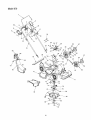
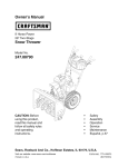
Model979
17
20
35
36
37
38
48
88
44_2
'\
f
\
57
41
_,
28
27
54
57
\
29
\
"1
i
30
18
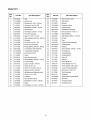
Model979
Ref.
No.
Part No.
Ref.
No.
Part Description
52.
Part No.
Part Description
1.
647-0004
Control Handle
748-0381
Pawl RH
2.
731-0904A
Upper Control Handle
3.
16864
53.
738-0137A
Shld Screw .340 ID x .285 OD
4.
731-0620
6 Spd. Rack Cable Bracket
Control Lever
748-0188B
Pawl LH
54.
748-0318
Wheel Rachet
5.
713-0397
Gear Insert
55.
736-0270
Bell Washer .265 ID x .75 OD
6.
732-0627
Shift Lever Spring
56.
710-0751
7.
731-0924
6 Speed Shift Lever
57.
731-1426
8.
731-0905A
Lower Control Housing
58.
738-0102
Hex Cap Screw 1/4-20 x .620
Hubcap
Shoulder Screw .498 x 1.445
9.
710-1667A
C Sunk Tap Screw #10 x .75 Lg
59.
736-0504
Wave Washer .510 ID x .750 OD
10.
731-0906
734-2004A
Wheel 8 x 2
746-0711A
Cable Mounting Cap
Drive Cable 51.0
60.
11.
61.
736-0105
12.
712-0324
Top Lock Nut 1/4-20
62.
710-1348
Spring Washer .401 ID x .870 OD
Screw 1/4-14 x .500
13.
746-0883
63.
710-0896
Screw 1/4-14 x .625
14.
710-1270
Control Housing
Oval C-Sunk Screw
64.
710-0654A
Hex Washer Screw 3/8-16 x 1.0
15.
746-1131
Control Cable 46"
65.
611-0064
16.
749-0439D
Upper Handle
66.
736-0204
Front Axle Assembly
Flat Washer .344 ID x .62 OD
17.
720-0241
67.
710-0703
18.
736-0451
Wing Nut
Saddle Washer .320 ID x .830 OD
68.
710-1242
Carriage Screw 1/4-20 x .75
Torx Screw
19.
710-1174
741-0492A
726-0240
Carriage Bolt 5/16-18 x 2.0
Cable Tie
69.
20.
70.
710-1241
Block Bushing
Hex Washer Screw
21.
749-0907B
Lower Handle
71.
731-1829
Front Axle Cover
27.
731-1901
Trail Shield
72.
754-0460
Belt 3/8 x 39.24
28.
732-0842
Trail Shield Wire
73.
656-0613
Pulley Assembly
29.
631-0066
Chute Assembly
74.
750-1071
30.
731-1832
75.
750-1070
31.
731-1833
Side Discharge Chute
Mulch Cover
76.
782-7597
Sleeve Spacer .88 ID x 1.13 OD
Sleeve Spacer .88 ID x 1.00 OD
Pivot Bracket
32.
782-0046B
Deck 21"
77.
710-0654A
Screw 3/8-18 x 1.0
33.
712-0397
Wing Nut
78.
782-7596
Control Arm
34.
710-0703
Carriage Bolt 1/4-20 x .75
79.
732-0807
35.
746-0939
6 Speed Cable
80.
711-1114
Torsion Spring
Pivot Shaft
36.
782-7574A
736-0526
Wave Washer 1.38 ID x .88 OD
736-0270
Cable Adjustment Bracket
Bell Washer .265 ID x .75 OD
81.
37.
82.
731-1828
Baffle
38.
712-0287
Hex Nut 1/4-20
83.
710-0653
Screw 1/4-20 x 3.75
Carriage Screw 1/4-20 x .50
Hex Nut 1/4-28
84.
753-0609
Blade Adapter Kit
85.
742-0741
21" Mulching Blade
736-0524A
Blade Bell Support
Hex Bolt 3/8-24 x 2.5
39.
710-0167
40.
712-0138
41.
782-7575A
42.
736-0329
Cable Mounting Bracket
Lock Washer 1/4
86.
87.
710-1257
43.
756-0625
Roller Cable
88.
731-1874
Chute Door
44.
738-0924
Shoulder Screw .375 ID x 1/4-14
89.
732-0819
Torsion Spring
45.
714-0104
Cotter Pin
90.
726-0111
46.
736-0286
Bowed Washer
91.
747-0965
Push Cap
Pivot Rod
47.
782-0565
731-1713B
734-2044
Single Lever Control Arm
Wheel 9 x 2
92.
48.
93.
720-0294
Discharge Chute
Grip
49.
712-0414
682-3052
Handle Bracket Assembly - RH
16855
Top Lock Tab Weld Nut 1/4-20
Ratchet Pawl Plate
94.
50.
682-3053
Handle Bracket Assembly - LH
51.
10622B
Plastic Spring Ratchet
19
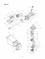
Model979
16
15
17
28
\
11
\
25
12
13
22
31
20
60
59
62
53
63
20
Model 979
Ref.
No.
Part No.
Ref.
No.
Part Description
Part No.
Part Description
1.
720-0223
Grip
33.
712-0896
Hex Jam Nut 1/4-28
2.
732-0803A
Spring Lever
34.
782-7598
Belt Keeper
3.
738-0529
Shoulder Nut .825 x .165 Lg.
35.
741-0600
Bearing
4.
710-0751
732-0849A
Extension Spring
736-0270
Cap Screw 1/4-20 x .620
Bell Washer .285 ID x .75 OD
36.
5.
37.
750-1050
Flange Spacer
6.
748-0318
Wheel Rachet
38.
682-0027A
Idler Bracket Assembly
7.
736-0369
Flat Washer .508 ID x 1.00D
39.
710-0299
Hex Cap Screw 1/4-28 x 1.0
8.
682-0531
Pivot Arm Assembly
40.
741-0682A
Bearing Sleeve
9.
750-0515
Spacer .510 ID x .70 OD
41.
736-0570
Flat Washer .885 ID x 1.45 OD
10.
741-0978
721-0329
Oil Seal
750-1056
Sleeve Bearing .504 ID x .830 OD
Shoulder
42.
11.
43.
721-0325
Plug
12.
710-0653
Tap Screw 1/4-20 x .375
44.
618-0253
Upper Housing Assembly
13.
682-7528
Chain Cover Assembly
45.
782-7601A
Cable Bracket
14.
741-0324
Flange Bearing .506 ID x .590 Lg
46.
741-0690
Bearing
15.
682-7526
Transmission Axle Assembly
47.
736-0616
Thrust Washer .504 ID x .70 OD
16.
618-0263A
782-7595
Pivot Bracket
710-0604A
Transmission Assembly
Hex Screw 5/16-18
48.
17.
49.
741-0324
Flange Bearing
18.
713-0453
Chain
50.
711-1168
Output Shaft 6T
19.
638-0012
Rear Axle Assembly
51.
717-1469
Gear 34T
20.
741-0522
Flange Bearing .506 ID x .715 Lg
52.
741-0674
Bearing
21.
732-0832
Torsion Spring
53.
717-1487
Pinion Shaft 10T
22.
750-0151
736-0314
Thrust Washer 3/8 x .70
710-1315
Spacer .550 ID x .750 OD
Screw 3/8-16 x .25
54.
23.
55.
736-0569
Thrust Washer .388 x .625
24.
711-0835
Clevis Pin .50 Dia x 4.82 Lg.
56.
618-0252
Lower Housing Assembly
25.
750-0807
Spacer .385 ID x .624 OD
57.
710-0642
Hex Screw 1/2-20 x .75
26.
782-0568
611-0066
Shaft Assembly
710-1652
Hgt Adjustment Spring Bracket
Screw 1/4-14 x .825
58.
27.
59.
664-0121
Grassbag
28.
714-0474
Cotter Pin
60.
747-0940A
29.
712-3025
Hex Jam Nut 5/16-24
61.
747-0939
Support Rod w/Rope Guide
Pivot Rod
30.
736-0425
Bell Washer .325 ID x .930 OD
62.
747-0937
Grassbag Frame
31.
756-0656
631-0071
Grassbag Cover
32.
736-3084
Pulley
Flat Washer .510 ID x 1.120 OD
63.
21
22
23
MANUFACTURER'S
LIMITED WARRANTY
FOR:
YaRD-MaN ,
The limited warranty
set forth below is given by MTD LLC
d.
with respect to new merchandise purchased and used in the
United States, its possessions and territories.
MTD LLC warrants this product against defects for a period
of two (2) years commencing on the date of original purchase
and will, at its option, repair or replace, free of charge, any
MTD LLC does not extend any warranty for products
sold or exported outside of the United States, its possessions and territories, except those sold through MTD
LLC's authorized channels of export distribution.
e.
Parts that are not genuine MTD parts are not covered by
this warranty.
f.
Service completed by someone other than an authorized
service dealer is not covered by this warranty.
Transportation charges and service calls are not
covered.
part found to be defective in materials or workmanship. This
limited warranty shall only apply if this product has been
operated and maintained in accordance with the Operator's
g.
Manual furnished with the product, and has not been subject
to misuse, abuse, commercial
use, neglect, accident,
improper maintenance,
alteration, vandalism, theft, fire,
No implied warranty,
water, or damage because of other peril or natural disaster.
Damage resulting from the installation or use of any acces-
applies after the applicable period of express written
warranty above as to the parts as identified. No other
sory or attachment not approved by MTD LLC for use with
the product(s) covered by this manual will void your warranty
as to any resulting damage.
express
Normal wear parts or components thereof are subject to separate terms as follows: All normal wear parts or component
failures will be covered on the product for a period of 90 days
regardless of cause. After 90 days, but within the two year
period, normal wear part failures will be covered ONLY IF
caused by defects in materials or workmanship of OTHER
component parts.
Normal wear parts and components
include, but are not limited to: batteries, belts, blades, blade
adapters, grass bags, rider deck wheels, seats, snow thrower
skid shoes, shave plates, auger spiral rubber, tires.
HOW TO OBTAIN SERVICE: Warranty service is available,
WITH PROOF OF PURCHASE, through your local autho-
merchantability
including any implied warranty
of
warranty,
fitness
whether
for
a particular
written
of
purpose,
or oral, except
as
mentioned above, given by any person or entity, including a dealer or retailer, with respect to any product, shall
bind MTD LLC. During the period of the warranty, the
exclusive remedy is repair or replacement of the product
as set forth above.
The provisions
as set forth in this warranty provide the
sole and exclusive
remedy arising from the sale.
MTD
LLC shall not be liable for incidental or consequential
loss or damage including, without limitation, expenses
incurred for substitute
or replacement
vices or for rental expenses to temporarily
ranted product.
lawn care serreplace a war-
Some states do not allow the exclusion or limitation of incidental or consequential
damages, or limitations on how long
rized service dealer. To locate the dealer in your area, check
your Yellow Pages, or contact MTD LLC at P.O. Box 361131,
Cleveland, Ohio 44136-0019, 1-800-800-7310,
1-330-220-
an implied warranty lasts, so the above exclusions or limitations may not apply to you.
In no event shall recovery of any kind be greater than the
4683 or log on to our Web site at www.yardman.com.
amount of the purchase price of the product sold. Alteration
This limited warranty does not provide coverage in the following cases:
a. The engine or component parts thereof. These items
carry a separate manufacturer's warranty. Refer to the
applicable manufacturer's warranty for terms and conditions.
b.
c.
of the safety features of the product shall void this warranty. You assume the risk and liability for loss, damage, or
injury to you and your property and/or to others and their
property arising out of the misuse or inability to use the product.
This limited warranty shall not extend to anyone other than
the original purchaser or to the person for whom it was pur-
Log splitter pumps, valves, and cylinders have a separate one year warranty.
Routine maintenance items such as lubricants, filters,
chased as a gift.
blade sharpening, tune-ups, brake adjustments, clutch
adjustments, deck adjustments, and normal deterioration
limited warranty gives you specific legal rights, and you
of the exterior finish due to use or exposure.
MTD LLC, P.O. BOX 361131 CLEVELAND,
HOW STATE LAW RELATES TO THIS WARRANTY:
may also have other
state.
OHIO 44136-0019
This
rights which vary from state to
1-800-800-7310