1
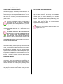
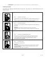
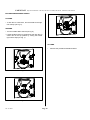
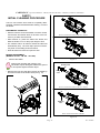
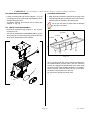
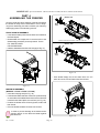
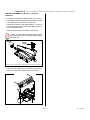
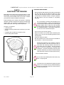
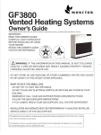
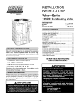
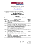
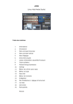
LB 302 • LB 502 • LB1002
LB 302 G • LB 502 G• LB 1002 G
OPERATION
MANUAL
CARPIGIANI CORPORATION OF AMERICA
3760 Industrial Drive • Winston-Salem, North Carolina 27105
336-661-9893 • 336-661-9895 (Fax)
TABLE OF CONTENTS
FORWARD ........................................................................................................................................................... 3
PART 1 - INSTALLATION ...................................................................................................................................... 4
UNCRATING .................................................................................................................................................... 4
POSITIONING THE MACHINE ........................................................................................................................... 4
MACHINE EQUIPPED WITH AIR COOLED CONDENSER ................................................................................... 5
MACHINE EQUIPPED WITH WATER-COOLED CONDENSER............................................................................. 5
WATER VALVE ADJUSTMENT.......................................................................................................................... 5
ELECTRICAL REQUIREMENTS ........................................................................................................................ 6
POWER SUPPLY ............................................................................................................................................ 6
WIRING ........................................................................................................................................................... 6
ELECTRICAL CONNECTIONS ........................................................................................................................... 6
BEATER ROTATION ......................................................................................................................................... 6
COMPLETING THE INSTALLATION .................................................................................................................... 7
MACHINE SAFETY SYSTEM - THERMAL RELAY .............................................................................................. 7
PROTECTION FOR THE OPERATOR ................................................................................................................ 7
PART 2 - EXPLANATION OF CONTROLS .............................................................................................................. 8
ICE CREAM DISPENSING HANDLE ................................................................................................................ 10
PART 3 - INITIAL CLEANING PROCEDURE ......................................................................................................... 11
PRELIMINARY CLEAN-OUT............................................................................................................................ 11
BEATER DISASSEMBLY (MODELS LB 302 - LB 502 - LB 1002) ....................................................................... 11
BEATER DISASSEMBLY (MODELS LB 302 G - LB 502 G - LB 1002 G) ............................................................. 12
FRONT DOOR DISASSEMBLY ....................................................................................................................... 12
ICE CREAM GATE DISASSEMBLY ................................................................................................................. 13
FILL CHUTE COVER DISASSEMBLY .............................................................................................................. 13
CLEANING OPERATIONS ............................................................................................................................... 13
PART 4 - ASSEMBLING THE FREEZER ............................................................................................................... 14
FRONT DOOR RE-ASSEMBLY ....................................................................................................................... 14
BEATER RE-ASSEMBLY (MODELS LB 302 - LB 502 - LB 1002) ...................................................................... 14
BEATER RE-ASSEMBLY (MODELS LB 302 G - LB 502 G - LB 1002 G) ............................................................. 15
PART 5 - SANITIZING THE FREEZER .................................................................................................................. 16
PART 6 - STARTING THE FREEZER .................................................................................................................... 17
ICE CREAM PRODUCTION (PROCESSING) .................................................................................................... 17
ICE CREAM CONSISTENCY ........................................................................................................................... 17
CHANGING ICE CREAM CONSISTENCY ......................................................................................................... 17
DISPENSING ICE CREAM .............................................................................................................................. 18
ICE CREAM DISPENSING HANDLE ................................................................................................................ 18
AFTERCOOLING ............................................................................................................................................ 19
PART 7 - CLEANING PROCEDURE ..................................................................................................................... 20
PART 8 - TECHNICAL INFORMATION ................................................................................................................. 23
PART 9 - MANTEINANCE .................................................................................................................................... 24
PART 10 - TROUBLESHOOT GUIDE ................................................................................................................... 25
© Copyright 1998, CARPIGIANI Corporation of America. All Rights Reserved.
CARPIGIANI Operation Manual - LB 302, LB 502, LB 1002, LB 302 G, LB 502 G, LB 1002 G
FORWARD
Thank you for selecting CARPIGIANI as your choice in equipment. CARPIGIANI machines are able to
meet today’s fast growing demands. Your CARPIGIANI freezer has been manufactured at one of the most
modern manufacturing plants and utilizes the most advanced equipment and technology available in the industry.
We at CARPIGIANI, take great pride and care in the manufacture of each and every freezer, using only the
finest components available, to provide you with years of trouble-free operation.
Over twenty-five years of experience in the manufacturing of dispensing equipment has guided us in the
preparation of this Operation Manual. PLEASE READ IT CAREFULLY. Keep it handy for future reference and
follow the instructions from the very first time your machine is put into service.
On the following pages you will find important information and procedures that describe the proper installation, sanitizing, operation, and maintenance of your CARPIGIANI machine. We feel certain that your full
compliance with these instructions will assure you of excellent performance, trouble-free operation, and profitable business for years to come.
USING THIS MANUAL
As you go through this manual, you will occasionally see special notes accompanied by this symbol:
Pay special attention to these notes - they contain special hints and precautions that are necessary for
the proper operation of your CARPIGIANI machine.
All technical data, pictures and drawings contained in this manual are not binding on the manufacturer, nor can the manufacturer be held liable
for any modification of the machine in part or whole. © Copyright 1998, CARPIGIANI Corporation of America. All rights reserved.
Page 3
Rev. 12/2002
CARPIGIANI Operation Manual - LB 302, LB 502, LB 1002, LB 302 G, LB 502 G, LB 1002 G
IMPORTANT!
• Remove the case by lifting it straight up and away from
the machine.
Failure to follow operational and maintenance procedures may result in damage to the unit and/or
void your warranty. CARPIGIANI Corporation will
not be held responsible for any machine that is
not properly operated or maintained.
• The machine is also secured to the skid with strapping.
Use caution when cutting the strapping as it may spring
out injuring you or damaging the machine.
• Free the machine from the skid.
• Remove the single screw at the bottom of each side
panel.
In the event this unit should malfunction, please contact
your CARPIGIANI distributor or an authorized service
agency.
• Remove the panels by sliding downward slightly, then
pull outward at the bottom and allow the panel to slide
down.
PART 1
INSTALLATION
• You may remove the protective plastic coating that has
been laminated to the panels by peeling it off.
Before starting this procedure, carefully inspect the shipping case to ensure the unit has not been dropped, tampered with, or abused in such a way as to indicate the
unit may have been damaged in transit.
POSITIONING THE MACHINE
If you notice any damage to the outside of the shipping case that may indicate possible hidden damage, make a notation of the damage on the bill of
lading before signing. Contact the carrier immediately
and request an inspection of damage. If this procedure is
not adhered to you may forfeit your right to file a damage
claim and be responsible for subsequent repair costs.
• The machine must stand level. Check the level condition by placing a level on the top of the freezer at each
corner.
• The freezer is equipped with 2 pivoting front wheels to
allow easy location. Move the machine to the desired
location.
• Lock the front wheels to prevent the freezer from moving.
Accurate leveling is necessary to allow for correct
drainage of the freezer barrel and to ensure correct overrun.
UNCRATING
• The case is secured to the skid with strapping.
Use caution when cutting the strapping as it may spring
out injuring you or damaging the machine.
Positioning the machine with pivoting front wheels
Uncrating
Rev. 12/2002
Page 4
CARPIGIANI Operation Manual - LB 302, LB 502, LB 1002, LB 302 G, LB 502 G, LB 1002 G
MACHINE EQUIPPED WITH AIR COOLED
CONDENSER
MACHINE EQUIPPED WITH WATER-COOLED
CONDENSER
• Machines with air-cooled condenser must be installed
at least 2 feet (24 inches) away from any wall or object
to allow the free circulation of air around the condenser
(ref. Fig. 1).
• If the unit is water-cooled, it should be located close to
the water supply and within six feet of a drain.
• Connect the fitting marked “WATER IN” to the cold water supply. Connect the fitting marked “WATER OUT” to
a drain (ref. Fig.2).
Insufficient air circulation effects the operation and
output capacity of the machine. If these clearances
are not maintained, the production capacity will
be reduced, cycling will increase, and the machine
may stop completely.
All plumbing must meet local or state codes.
WATER
INLET
Water cooled condenser:
A≥ 4 in
B≥ 6 in
WATER
OUTLET
Air cooled condenser:
A≥ 24 in
B≥ 6 in
Figure 2
WATER VALVE ADJUSTMENT
A
The water valve is preset at the factory.
Proceed as follows if an adjustment is required:
• To maintain a head pressure of 235-255 psi while the
compressor is running, attach a refrigeration high pressure
gauge to the compressor’s high side discharge port.
B
• Open the water valve clockwise to increase the pressure or
counter clockwise to decrease the pressure (ref. Fig. 3).
Figure 1
• It is necessary to clean the condenser each month to
eliminate dust, paper, etc., which may obstruct it.
Failure to do so may result in potential damage to the
machine and improper functioning.
• The machine should be within six feet of the power supply (a plug and receptacle or unfused disconnected).
• Position the machine to allow easy access for cleaning, servicing and maintenance.
• Position the machine away from direct sunlight.
For every 2EF over 68EF, the machine’s performance
will decrease by approximately 1%.
Figure 3
• Once the machine is set in position, it should be leveled as accurately as possible.
Never expose water-cooled machines to temperatures at or below 32°F. without first draining the
water from the condenser. Serious damage to the
machine can occur if it is not properly drained.
Page 5
Rev. 12/2002
CARPIGIANI Operation Manual - LB 302, LB 502, LB 1002, LB 302 G, LB 502 G, LB 1002 G
ELECTRICAL REQUIREMENTS
ELECTRICAL CONNECTIONS
• The wiring used to operate this freezer must be in
accordance with the National Electrical Code and/or local electrical codes, rules and regulations.
• After you remove the panel on the left side of the machine, the wiring connection box can be found on the
bottom of the frame and is labeled “Connect Power Line
Here” (ref. Fig. 4).
• The machine must be properly grounded. We recommend that a licensed electrician install the power
supply.
• Feed the power line through the access hole located at
the bottom deck directly below the wiring connection
box.
POWER SUPPLY
• Connect the power line to the machine’s power lines
and wiring connection box.
The power supply must be adequate enough to meet
requirements at all times. Voltage fluctuations with the
machine in operation should not exceed plus or minus
5% of the normal or rated voltage.
• After connecting, the power line should be fastened to
the wiring connection box with appropriate electrical
hardware.
• In all installations, the machine must be properly
grounded. Because all high voltage components (the
controls are 24 volts) are connected with flexible conduit or cord, adequate ground continuity is assured by
running and fastening a ground line to the machine junction box ground lug (ref. Fig. 4).
WIRING
• Adequate wiring must be provided with respect to wire
size or gauge. Unless otherwise required by the local
Electrical Codes, the same gauge wire at the machine
junction box should be used for the direct power line. A
separate circuit breaker with adequate fuse protection
should be employed.
• An unfused disconnected switch or a properly sized
plug and receptacle within 6 feet of the freezer, is recommended.
CARPIGIANI freezers are equipped with protection for the
beater motor. Should the line voltage drop, or in the unlikely event a short circuit occurs, the overload protector
will automatically disconnect the starter and the machine
will stop immediately so that no permanent damage can
be caused to the motor.
Figure 4
The compressor is also internally protected. If the Klixon
protector trips due to an overload, the protector must first
cool down for several minutes before the compressor can
be restarted.
Rev. 12/2002
BEATER ROTATION
After the electrical connections have been completed
check the rotation of the beater which should be counterclockwise when facing the front of the machine.
Page 6
CARPIGIANI Operation Manual - LB 302, LB 502, LB 1002, LB 302 G, LB 502 G, LB 1002 G
COMPLETING THE INSTALLATION
PROTECTION FOR THE OPERATOR
The following pages contain important information and
procedures that describe the proper sanitizing, operation,
and maintenance of your CARPIGIANI machine. We feel
certain that your full compliance with these instructions
will ensure the excellent performance and trouble-free
operation of the machine and a profitable business for
years to come.
A microswitch has been placed on the door of the barrel
with the beater assembly. The switch will immediately
stop the machine when the door is opened. When the
machine stops, the monitor will display "PT." The display will blink if the machine was running when it was
stopped. The display will be steady (not blinking) if the
machine was already stopped when the door was
opened. After closing the door, the machine remains
stopped and the display resets.
Failure to closely follow set-up and maintenance
procedures can void your warranty. CARPIGIANI
Corporation will not be responsible for any machine
not properly maintained.
Make sure the machine is stopped before opening the front door.
In the event this unit should malfunction, please contact
your CARPIGIANI Distributor or an authorized service
agency.
EXTREME CARE MUST BE TAKEN WHEN REMOVING SIDE, REAR, OR CONTROL BOX PANELS. ALWAYS TURN THE MACHINE TO THE
OFF POSITION. ALSO TURN OFF THE DISCONNECT SWITCH ON THE ELECTRICAL SUPPLY LINE
BEFORE EXPOSING ANY ELECTRICAL CONNECTIONS
AND/OR MOVING PARTS, SUCH AS BELTS, PULLEYS,
FAN BLADES AND BEATER.
MACHINE SAFETY SYSTEM - THERMAL RELAY
The Thermal Relay monitors amperage draw of the beater
motor. When maximum values are reached, the machine
will stop and the monitor will blink "RT" which is the code
that indicates the THERMAL CUT-OUT has been tripped.
Upon automatic resetting of the thermal relay, the display
will stop blinking. Before restarting operation, it is
important to investigate the reason the Thermal Cut-out
tripped. To restart the machine, press the desired button.
PRESSURE SWITCH
The Pressure Switch protects the cooling system
compressor. This switch will stop the compressor in the
event of water flow interruption (water-cooled system) or
air flow obstruction (air-cooled system); resetting is automatic.
If the compressor runs too long, or the machine continually stops and restarts it may indicate cooling is insufficient. Call your authorized service technician.
Page 7
Rev. 12/2002
CARPIGIANI Operation Manual - LB 302, LB 502, LB 1002, LB 302 G, LB 502G, LB 1002 G
PART 2
EXPLANATION OF CONTROLS
4
1
2
5
6
7
3
00
A
B
Control Panel
MONITORING CONSISTENCY
The ice cream consistency monitor (Hard-O-Tronic) consists of 3 parts:
00
Ref.1 DISPLAY displaying set calibration values
Ref.2 PUSH-BUTTONS for variation of calibration values
Ref.3 LED BAR for checking all processing phases in a real time.
Rev. 3/98
Page 8
CARPIGIANI Operation Manual - LB 302, LB 502, LB 1002, LB 302 G, LB 502G, LB 1002 G
PUSHBUTTON PANEL
The machine has a diaphragm pushbutton panel on the front side. Each button has a symbol representing the corresponding function:
Ref. 4
Push-button CLEANOUT
When pressed, it just controls beater rotation, while the freezing system is cut
out.
Three minutes after inserting this function, the machine automatically sets to
"STOP" in order to avoid an excessive wear of beater and barrel.
Ref. 5
Push-button DISPENSE
When pressed, it controls beater rotation at high speed for an easy dispense of
the product .
Attention!
Three minutes after selecting and inserting this function, the machine
automatically sets to STOP in order to avoid an excessive wear of beater and
barrel.
Ref. 6
Push-button ICE CREAM PRODUCTION
When pressed, it automatically controls beater and compressor running.
Ice cream consistency is controlled by CARPIGIANI exclusive electronic
system called HARD-O-TRONIC, through which the best ice cream
processing value can be reached.
Ref.7
Push-button STOP
When pressing it, machine stops.
Attention!
If the machine is left in STOP more than 30 minutes and no other push-button
is pushed, the electronic card automatically switches off in order to reduce
energy consumption.
Press STOP in order to turn on the machine.
Page 9
Rev. 3/98
CARPIGIANI Operation Manual - LB 302, LB 502, LB 1002, LB 302 G, LB 502 G, LB 1002 G
ICE CREAM DISPENSING HANDLE
LOCKING
• To lock the ice cream door, turn the handle to the right
until it stops (ref Fig. 5).
OPENING
• Turn the handle 90E to the left (ref Fig. 6).
• Lift the handle and the ice cream door then lock the ice
cream door in the top position by turning the handle
right until it stops (ref Fig. 7).
Figure 7
CLOSING
•
Figure 5
Figure 6
Rev. 12/2002
Page 10
Reverse the procedures described above.
CARPIGIANI Operation Manual - LB 302, LB 502, LB 1002, LB 302 G, LB 502 G, LB 1002 G
PART 3
INITIAL CLEANING PROCEDURE
This is a new machine and it must be completely disassembled, washed and sanitized before starting. Proceed
as follows:
PRELIMINARY CLEAN-OUT
• With the machine off and the beater front door closed,
use the hose and shutoff valve on the front of the machine to put water into the barrel.
Beater mounted on models: LB 302 - LB 502
• With machine on, press the "Clean Out" button and
allow the beater to run for the proper length of time.
• The machine will run for about 3 minutes and then will
automatically stop. The timer helps prevent unnecessary wear on the sliding shoes and barrel.
• Drain all water from barrel and open the door.
BEATER DISASSEMBLY
(MODELS LB 302 - LB 502 - LB 1002)
•
Beater mounted on models: LB 1002
Figure 9
Remove the beater.
Perform this operation with extreme care.
The beater may be damaged if it falls to the ground
or is impacted against another object.
• Remove the rear plug seal then remove the beater lip
seal from its seat on the beater shaft (ref Fig. 10).
Beater seal
Plug
seal
Beater mounted on models: LB 302 - LB 502
Plug seal
Stuffing
box
Beater mounted on models: LB 1002
Figure 8
Figure 10
Page 11
Rev. 12/2002
CARPIGIANI Operation Manual - LB 302, LB 502, LB 1002, LB 302 G, LB 502 G, LB 1002 G
BEATER DISASSEMBLY (MODELS LB 302 G - LB 502 G LB 1002 G)
FRONT DOOR DISASSEMBLY
• Remove beater with care, paying attention not to damage the sliding shoes.
• Open the door by rotating it on its hinge (ref. Fig. 13).
• Lift the door locking lever and shift it to the right (ref. Fig. 13).
Perform this operation with extreme care.
The beater may be damaged if it falls to the ground
or is impacted against another object.
• Disassemble sliding shoes, completely (ref. Fig. 12).
• Remove the beater lip seal from its seat on the beater
shaft (ref. Fig. 12).
• The sliding shoes mounted on the beater are "self-adjusting". An accurate cleaning ensures the system will
perform in full working order.
Figure 13
• Lift the door and remove it (ref. Fig. 14).
• To perform cleaning operations, remove all movable parts
and seal with barrel.
Figure 11
Beater
seal
Sliding
shoes
Beater mounted on models: LB 302 G - LB 502 G - LB 1002 G
Figure 12
Rev. 12/2002
Figure 14
Page 12
CARPIGIANI Operation Manual - LB 302, LB 502, LB 1002, LB 302 G, LB 502 G, LB 1002 G
ICE CREAM GATE DISASSEMBLY
CLEANING OPERATIONS
• Lift the ice cream gate and remove OR (Ref. 1 - Fig. 15)
from sliding rod of ice cream gate and withdraw it which
will also release the lever.
• Wash all parts in lukewarm water (80-90 F) using a mild
non-foaming detergent. Scrub each of the parts with the
cleaning brushes provided in the Start-Up Kit.
• To perform cleaning, also remove the ice cream gate
OR (Ref. 2 - Fig. 15).
Do not use hot water on plastic parts as damage
to the parts can result.
FILL CHUTE COVER DISASSEMBLY
• Remove the horizontal hinge pin (Ref. 3 - Fig. 15) then
remove the cover.
4) Air Dry
• The cover is provided with a small bulkhead (Ref.4 - Fig.15),
which prevents ice cream from going up into the fill chute
which must disassembled to be cleaned.
3) Sanitize
2) Rinse
1) Wash
3
4
Figure 16
Using your three-tank sink, wash, rinse and sanitize all of
the disassembled machine parts. Mix the sanitizing
solution to a 200ppm concetration with warm water. Allow
the parts to soak in the sanitizing solution for 3-5 minutes
before removing. Allow the parts to air-dry on the clean,
sanitized counter at the end of the sink.
2
Do not towel of sponge dry these parts.
1
Figure 15
Page 13
Rev. 12/2002
CARPIGIANI Operation Manual - LB 302, LB 502, LB 1002, LB 302 G, LB 502 G, LB 1002 G
PART 4
ASSEMBLING THE FREEZER
Beater seal
Once the parts have been washed, rinsed and sanitized,
the freezer is ready to be re-assembled. Prior to beginning the re-assembly procedure, sanitize your hands by
submerging them in the sanitizing solution.
Plug
seal
FRONT DOOR RE-ASSEMBLY
• Lubricate all rubber parts with the lubricant included in
the Start-Up Kit.
• Reassemble the components in reverse order to the
disassembly procedure previously stated. That is:
Beater mounted on models: LB 302 - LB 502
Beater seal
FILL CHUTE COVER
ICE CREAM DOOR
• Insert the assembled front door on the hinge (ref. Fig. 17).
Plug
seal
Beater mounted on models: LB 1002
Figure 18
• Push beater deeply and, at the same time, turn it in
order to lock the end of beater shaft into its seat.
Figure 17
BEATER RE-ASSEMBLY
(MODELS - LB 302 - LB 502 - LB 1002)
• Insert the rear plug seal (ref. Fig. 18).
• Lubricate the beater seal with a series of 3 pea size drop
on each side of the rubber beater seal, with the lubricant
included in the Start-Up Kit, then mount it (ref. Fig. 18).
• Position the beater into the freezing barrel; hold it with
both hands.
• Push the beater toward the bottom of the barrel.
In order to prevent damage to the beater and/or
freezing barrel, do not strike the beater against
the barrel rim.
Rev. 12/2002
Figure 19
Page 14
CARPIGIANI Operation Manual - LB 302, LB 502, LB 1002, LB 302 G, LB 502 G, LB 1002 G
BEATER RE-ASSEMBLY (LB 302 G - LB 502 G LB1002 G)
• Completely assemble the sliding shoes (ref. Fig. 20).
• Lubricate the beater lip seal with the lubricant included
in the Start-Up Kit and mount it (ref Fig. 20).
• Position the beater into the freezing barrel. To do that,
hold it with both hands and press the sliding shoes so
that it is easier to insert.
• Push the beater toward the bottom of the barrel.
In order not to damage the sliding shoes and/or
the freezing barrel, do not strike the beater against
the barrel rim.
Beater
seal
Sliding
shoes
Beater mounted on models: LB 302 G - LB 502 G - LB 1002 G
Figure 20
• Push the beater deeply and, at the same time, turn it in
order to lock the end of beater shaft into its seat.
Figure 21
Page 15
Rev. 12/2002
CARPIGIANI Operation Manual - LB 302, LB 502, LB 1002, LB 302 G, LB 502 G, LB 1002 G
PART 5
SANITIZING THE FREEZER
SANITIZING PROCEDURES
• Mix the sanitizer (Stera Sheen green label or equivalent)
into the clean pail with at least two gallons of warm
water. Mix the sanitizer and water to make a 200-PPM
concentration of sanitizer solution. Using the spatula,
stir the solution until the sanitizer is completely
dissolved.
Before filling the machine with your liquid product, it must
be sanitized. The cleaning and sanitizing frequency cycles
must comply with all health codes in your area. Contact
your Board of Health for additional information.
Proper sanitizing of the machine is important. Sanitizing
retards the growth of bacteria and ensures excellent test
results when your machine is inspected by your local
health department and/or agriculture department.
Do not exceed the formula recommended by the
sanitizer manufacturer – higher concentrations will
not increase the effectiveness. Do not use straight
chlorine bleach since it does not clean properly
and will damage plastic components. Do not leave
the sanitizing solution in the freezer longer than
on hour as it can corrode some parts.
To begin, you will need:
• A clean bucket.
• Sanitizer (sample packets were included in your StartUp Kit).
• Pour the mix into the mixing tanks.
• A spatula (also included in the Start-Up Kit).
• With the machine off and the beater assembly door
closed, pour a non-corrosive sanitizing solution into the
freezing barrel.
• A brush with plastic bristles.
• Push the “Cleanout” button.
• Run the machine for the correct time recommended for
this procedure – about 20-30 seconds.
Running the machine in the “Cleanout” mode for
excessive periods of time with the barrel empty or
with water and cleansing solutions will wear out
the beater shoes very quickly. Run the machine
ONLY for the time necessary to complete these
operations. To avoid unnecessary wear of the sliding shoes and barrel, the machine will automatically
stop after three minutes of uninterrupted running.
•
Drain all sanitizer solution.
Do not touch the sterilized parts with hands, napkins, or anything else.
Sanitizing Kit
The machine is now sanitized and ready to be filled
with mix. Do not wipe aout any residual sanitizing
solution from the tank as this will contaminate the
machine with bacteria.
Rev. 12/2002
Page 16
CARPIGIANI Operation Manual - LB 302, LB 502, LB 1002, LB 302 G, LB 502 G, LB 1002 G
PART 6
STARTING THE FREEZER
ICE CREAM CONSISTENCY
A
B
ICE CREAM PRODUCTION (PROCESSING)
• Wash, sterilize, and thoroughly rinse the machine before use.
00
• Pour the desired quantity of mix into the barrel through
the front lid fill chute. Follow the minimum and maximum quantities shown in the table.
Hard-O-Tronic
CARPIGIANI sets the optimal ice cream consistency value
according to the mix being used. Hard-O-Tronic constantly
maintains ice cream in optimal condition. However, the
operator can also set “personalized” custom processing
cycles with the LB series.
• Before filling the machine with mix, ensure the front door
and ice cream gate are properly closed.
• Push the “Production” button. The machine will start
the processing cycle by beating and cooling the mix.
• The LED lights on the Hard-O-Tronic display will light in
High butter fat ice cream may require a higher consistency, while ice cream with low fat content (such as
shebert) requires a lower consistency setting.
CHANGING ICE CREAM CONSISTENCY
• To vary ice cream consistency, press the button (ref. B)
on the display panel while the machine is processing
ice cream.
• To achieve a harder ice cream, increase the setting value
displayed on the monitor (ref. A) by pushing the up arrow.
Production Button
• To achieve a softer ice cream, decrease the setting value
displayed on the monitor by pressing the down arrow.
sequence, indicating the status of processing. When
the LED panel blinks and you hear an audible alarm,
the processing cycle and the ice cream is ready to be
dispensed. The beater will continue to run, but the compressor has stopped.
EXAMPLE:
To vary the consistency value from 10 to 7:
• Press the button for ice cream processing.
LED's
If ice cream is not dispensed soon after processing is
completed, beating of the ice cream will continue
while the Hard-O-Tronic system continuously monitors the consistency. If the consistency decreases,
the Hard-O-Tronic system will restart the compressor and processing to restore the ice cream to its
optimal thickness and consistency.
Ice Cream Processing
• Repeatedly press the down arrow button until the value
7 is displayed. The new consistency value is immediately stored.
Page 17
Rev. 12/2002
CARPIGIANI Operation Manual - LB 302, LB 502, LB 1002, LB 302 G, LB 502 G, LB 1002 G
• At the end of the processing cycle, the ice cream consistency value will be 7 instead of 10.
ICE CREAM DISPENSING HANDLE
LOCKING
• Lock the ice cream gate turning the handle to the right
until it stops.
A typical value is 10. The new value will remain stored
until it is changed again.
Hourly output may vary depending upon: room and
cooling water temperature, type and quality of mix
used, and the consistency value that is set in the
machine.
OPENING
• Turn the handle 90° to the left (ref. Fig. 22).
• Lift the handle and the ice cream gate (ref. Fig. 23).
• Lock the ice cream gate on top by turning the handle to
the right until it stops (ref. Fig 24).
DISPENSING ICE CREAM
When the production cycle is over (indicated by blinking
LEDs and an audible alarm), ice cream may be dispensed
from the barrel as follows:
• Place a container on the shelf under the ice cream door.
• Turn the ice cream gate handle.
• Lift the handle together with the ice cream gate.
• Push the “Distribution” button.
Figure 22
Distribution
Figure 23
Stop
• Press “Stop” when all product is removed.
To avoid unnecessary wear of the beater shoes
and barrel, the machine returns to the stop mode
after 3 minutes is non-use.
Rev. 12/2002
Figure 24
CLOSING
• Repeat the procedures (above) in reverse order.
Page 18
CARPIGIANI Operation Manual - LB 302, LB 502, LB 1002, LB 302 G, LB 502 G, LB 1002 G
AFTERCOOLING
This function (which is an exclusive feature of all LB models) is very useful in models with larger output capacity (2
containers per cycle or more).
If ice cream in each container needs further preparation,
such as garnish and variegation before storage, ice cream
that remains inside the machine at high speed dispense
may lose its original thickness.
At any moment during extraction, and when the operator
chooses, you may press the Production button to cool
the ice cream again.
The result is a steady consistency of ice cream, from the
beginning to the end of extraction.
After-cooling begins each time the Production button is pressed and runs for a duration of 20 seconds.
Distribution - Production
Page 19
Rev. 12/2002
CARPIGIANI Operation Manual - LB 302, LB 502, LB 1002, LB 302 G, LB 502 G, LB 1002 G
PART 7
CLEANING PROCEDURE
Cleaning and sanitizing schedules for your freezer are
determined by your local Health Department and / or
Department of Agriculture and must be followed
accordingly. Check with your local organization prior to
determining your cleaning schedule.
After determining your schedule, remove any ice cream
Beater mounted on models: LB 302 - LB 502
remaining in the barrel. Proceed as follows:
PRELIMINARY CLEAN-OUT
• With the machine off and the beater front door closed,
use the hose and shutoff valve on the front of the machine to put water in the barrel.
• Turn the machine on then press the Cleanout button
and let the beater run for the specified time. The machine will run for about three minutes then automatically stop. This helps prevent unnecessary wear on the
sliding shoes and barrel.
Beater mounted on models: LB 1002
Figure 26
• Drain all water from the barrel then open the door to
remove the beater.
Beater seal
BEATER DISASSEMBLY
(MODELS LB 302 - LB 502 - LB 1002)
•
Plug
seal
Remove the beater.
Perform this operation with extreme care.
The beater may be damaged if it falls to the ground
or is impacted against another object.
• Remove the rear plug seal then remove the beater lip
seal from its seat on the beater shaft (ref Fig. 27).
Beater mounted on models:LB 302 - LB 502
Plug seal
Stuffing
box
Beater mounted on models: LB 1002
Figure 25
Rev. 12/2002
Figure 27
Page 20
CARPIGIANI Operation Manual - LB 302, LB 502, LB 1002, LB 302 G, LB 502 G, LB 1002 G
BEATER DISASSEMBLY (MODELS LB 302G - LB 502G - LB
1002G)
FRONT DOOR DISASSEMBLY
• Remove beater with care, paying attention not to damage the sliding shoes.
• Open the door by rotating it on its hinge (ref. Fig. 30).
• Lift the door locking lever and shift it to the right (ref. Fig. 30).
Perform this operation with extreme care.
The beater may be damaged if it falls to the ground
or is impacted against another object.
• Disassemble sliding shoes, completely (ref. Fig. 29).
• Remove the beater lip seal from its seat on the beater
shaft (ref. Fig. 29).
• The sliding shoes mounted on the beater are "self-adjusting". An accurate cleaning ensures the system will
perform in full working order.
Figure 30
• Lift the door and remove it (ref. Fig. 31).
• To perform cleaning operations, remove all movable parts
and seal with barrel.
Figure 28
Beater
seal
Sliding
shoes
Beater mounted on models: LB 302 G - LB 502 G - LB 1002 G
Figure 29
Figure 31
Page 21
Rev. 12/2002
CARPIGIANI Operation Manual - LB 302, LB 502, LB 1002, LB 302 G, LB 502 G, LB 1002 G
ICE CREAM GATE DISASSEMBLY
CLEANING OPERATIONS
• Lift the ice cream gate and remove OR (Ref. 1 - Fig. 32)
from sliding rod of ice cream gate and withdraw it which
will also release the lever.
• Wash all parts in lukewarm water (80-90 F) using a mild
non-foaming detergent. Scrub each of the parts with the
cleaning brushes provided in the Start-Up Kit.
• To perform cleaning, also remove the ice cream gate
OR (Ref. 2 - Fig. 32).
Do not use hot water on plastic parts as damage
to the parts can result.
FILL CHUTE COVER DISASSEMBLY
• Remove the horizontal hinge pin (Ref. 3 - Fig. 32) then
remove the cover.
4) Air Dry
3) Sanitize
• The cover is provided with a small bulkhead (Ref.4 - Fig.32),
which prevents ice cream from going up into the fill chute
which must disassembled to be cleaned.
2) Rinse
1) Wash
3
4
Using your three-tank sink, wash, rinse and sanitize all of
the disassembled machine parts. Mix the sanitizing
solution to a 200ppm concetration with warm water. Allow
the parts to soak in the sanitizing solution for 3-5 minutes
before removing. Allow the parts to air-dry on the clean,
sanitized counter at the end of the sink.
Do not towel of sponge dry these parts.
2
FRONT DOOR RE-ASSEMBLY
(see Part IV - Page 14)
1
BEATER RE-ASSEMBLY (LB302 - LB502-LB1002)
(see Part IV - Page 14)
Figure 32
BEATER RE-ASSEMBLY (LB302G - LB502G LB1002G)
(see Part IV - Page 15)
SANITIZING THE FREEZER
(see Part V - Page 16)
Rev. 12/2002
Page 22
CARPIGIANI Operation Manual - LB 302, LB 502, LB 1002, LB 302 G, LB 502 G, LB 1002 G
PART 8
TECHNICAL INFORMATION
Model
Weight
lbs
Power
input
Hourly
production
Qt. of mix per batch
min.
max.
LB 302
484
3,7 kW
11 Gal. **
3 Qts.
8 Qts.
LB 502
650
6,5 kW
19 Gal. **
7 Qts.
14 Qts.
LB 1002
990
9,5 kW
40 Gal. **
12 Qts.
20 Qts.
LB 302 G
528
3,7 kW
16 Gal. *
3 Qts.
8 Qts.
LB 502 G
700
6,5 kW
17 Gal. *
7 Qts.
12 Qts.
LB 1002 G
1052
9,5 kW
35 Gal. *
12 Qts.
20 Qts.
* Output based on 4 batches per Hour at 40% overrun
** Output based on 4 batches per hour at 60% overrun
D
H
W
Measuring Dimensions
TECHNICAL INFORMATION
MODEL
LB 302
LB 502
LB 1002
H
55"
55"
55"
D
35"
40"
47"
W
20"
24"
26"
MODEL
LB 302 G
LB 502 G
LB 1002 G
Page 23
H
55"
55"
55"
D
35"
40"
47"
W
20"
24"
26"
Rev. 12/2002
CARPIGIANI Operation Manual - LB 302, LB 502, LB 1002, LB 302 G, LB 502 G, LB 1002 G
PART 9
MANTEINANCE
Your CARPIGIANI machine has been designed, engineered and manufactured to achieve high performance
and long durability.
Any servicing operation requiring the
opening of machine panels must be carried
out with machine set to stop and disconnected from main switch!
The life expectancy of a machine, any machine, does
not depend only on the quality of its components and
design, but also on the beneficial effects of basic
maintenance procedures.
Cleaning and lubricating moving parts is
forbidden!
It is important to you, therefore, to become familiar with a
few of these basic procedures:
• Remove O-rings only with the O-ring extractor supplied
with the machine.
• Clean the machine according to the instructions.
Repairs of electrical and freezing plants
must be carried out by skilled engineers!
• Lubricate all O-rings and seals, as instructed.
Operations necessary to proper machine running are such
that most of servicing is completed during production
cycle.
Servicing operations, such as cleaning of parts in contact
with the product, replacing of beater seal, disassembling
of beater assembly are to be carried out at the end of a
working day, so as to speed up serving operations required.
Here below you can find a list of routine servicing operations:
• The wearing or the improper cleaning of the beater shaft
seals, will result in leakage from the rear. Check the
drip chute pans frequently and replace seals, when so
necessary.
• Replace any O-ring that has a nick in it.
If not replaced, it will leak and interfere with the proper
performance of the machine.
• When all the spare parts supplied with the machine are
used, re-order immediately. Do not wait until the part is
required again.
• NEVER use the AUTO position for washing, sanitizing
and initially filling the freezing cylinder.
• Cleanout and replacement of beater seal
During the washing and sanitizing period, run the
machine only for the time strictly necessary for
this operation.Prolonged use of the beater in the
Cleaning position may cause severe damage to
the machine.
Cleaning should be carried out at the end of a working
day. Replacement of beater seal is necessary only after
checking the stuffing box, or in the event that product
drips inside the drip tray.
• Cleanout of beater assembly
At the end of a working day
• Always wash metal, plastic or rubber parts in lukewarm
water. NEVER, NEVER USE HOT WATER!
• Cleanout of sliding shoes
At the end of a working day
If your Model is an air cooled machine, its efficiency depends on the air cooled condenser.
The fins of the condenser must be cleaned
every two or three months to assure efficiency.
• Cleanout of panels
To be carried out daily with neutral soap , seeing to it
that cleansing solution never reaches beater assembly at its inside.
• Cleanout and sterilization
At the end of each working day, according to procedures
described in section Part VII.
Never use abrasive sponges to clean machine and
its parts, as it might scratch their surfaces.
Rev. 12/2002
Page 24
CARPIGIANI Operation Manual - LB 302, LB 502, LB 1002, LB 302 G, LB 502 G, LB 1002 G
PART 10
TROUBLESHOOT GUIDE
IRREGULARITY
CAUSE
PROCEDURE
Machine does not start
Main switch is off
Switch it on
Machine unplugged
Check and plug in
Machine is not set at PRODUCTION
Check push button for
PRODUCTION is lit
Front lid is not closed well
Check front lid closure
Watercooled machine:
water does not circulate
Open water tap
Compressor starts and
then stops after a few
seconds without ice cream
being thick
Check that hose is neither
squashed nor doubled up
Aircooled machine:
Check that rear of machine air
does not circulate is at least 50 cm
from wall.
Clean obstruction from the condenser
No gas
Check leakage and weld
Pressure switch has broken
down
Check connection
and replace, if need be
Machine runs but no
ice cream comes from
ice cream door
No sugar in the mix
Allow to thaw, then modify
or replace the mix
Machine works but
ice cream is too soft
Too much sugar in
the mix
Modify or replace
the mix
Mix in drip drawer
Beater seal missing
or ruined
Install if missing
Replace if ruined
Ice cream comes out
from behind front lid
Gasket missing or not
properly installed
Check and fix or replace
Bacteria tests show
too high bacteria charge
Too high bacteria
charge in the mix
Improve preparation
procedure by sterilizing all
containers, spoons, etc.,
and have mix analyzed
before pouring it into the machine
Machine not clean
enough
Empty and thoroughly
wash the machine.
Carry out sterilization.
After 15 minutes processing
mix has not frozen and the
machine returns to Stop
Page 25
Rev. 12/2002