1
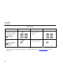
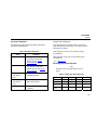
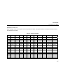
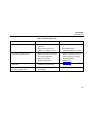
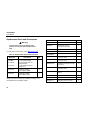
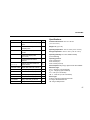
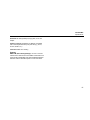
GasAlert Max
H2S, CO, O2, Combustibles
1, 2, 3, and 4 Gas Detectors
User Manual
D1430/4 [English]
iERP: 122414
© BW Technologies 2006. All rights reserved. Printed in Canada.
All product names are trademarks of their respective companies.
Limited Warranty & Limitation of Liability
BW Technologies LP (BW) warrants this product to be free from defects in material and workmanship under normal use and service for a period of two years,
beginning on the date of shipment to the buyer. This warranty extends only to the sale of new and unused products to the original buyer. BW’s warranty
obligation is limited, at BW’s option, to refund of the purchase price, repair, or replacement of a defective product that is returned to a BW authorized service
center within the warranty period. In no event shall BW’s liability hereunder exceed the purchase price actually paid by the buyer for the Product.
This warranty does not include:
a) fuses, disposable batteries or the routine replacement of parts due to the normal wear and tear of the product arising from use;
b) any product which in BW’s opinion, has been misused, altered, neglected or damaged by accident or abnormal conditions of operation, handling or use;
c) any damage or defects attributable to repair of the product by any person other than an authorized dealer, or the installation of unapproved parts on the
product; or
The obligations set forth in this warranty are conditional on:
a) proper storage, installation, calibration, use, maintenance and compliance with the product manual instructions and any other applicable
recommendations of BW;
b) the buyer promptly notifying BW of any defect and, if required, promptly making the product available for correction. No goods shall be returned to BW
until receipt by the buyer of shipping instructions from BW; and
c) the right of BW to require that the buyer provide proof of purchase such as the original invoice, bill of sale or packing slip to establish that the product is
within the warranty period.
THE BUYER AGREES THAT THIS WARRANTY IS THE BUYER’S SOLE AND EXCLUSIVE REMEDY AND IS IN LIEU OF ALL OTHER WARRANTIES,
EXPRESS OR IMPLIED, INCLUDING BUT NOT LIMITED TO ANY IMPLIED WARRANTY OF MERCHANTABILITY OR FITNESS FOR A PARTICULAR
PURPOSE. BW SHALL NOT BE LIABLE FOR ANY SPECIAL, INDIRECT, INCIDENTAL OR CONSEQUENTIAL DAMAGES OR LOSSES, INCLUDING
LOSS OF DATA, WHETHER ARISING FROM BREACH OF WARRANTY OR BASED ON CONTRACT, TORT OR RELIANCE OR ANY OTHER THEORY.
Since some countries or states do not allow limitation of the term of an implied warranty, or exclusion or limitation of incidental or consequential damages, the
limitations and exclusions of this warranty may not apply to every buyer. If any provision of this warranty is held invalid or unenforceable by a court of competent
jurisdiction, such holding will not affect the validity or enforceability of any other provision.
BW Technologies LP
2840 – 2nd Ave. SE
Calgary, AB
Canada T2A 7X9
BW America
3279 West Pioneer Parkway
Arlington, TX
USA 76013
BW Europe
5 Canada Close
Banbury, Oxfordshire
United Kingdom OX16 2RT
Table of Contents
Title
Page
Introduction............................................................................................................................................ 1
Contacting BW Technologies................................................................................................................ 2
Safety Information - Read First ............................................................................................................. 2
Getting Started ...................................................................................................................................... 6
Activating the Detector ........................................................................................................................ 10
Self-Test ...................................................................................................................................... 10
Battery Test ................................................................................................................................. 13
Pump Test ................................................................................................................................... 13
Self-Test Pass ............................................................................................................................. 14
Self-Test Fail ............................................................................................................................... 14
Deactivating the Detector.................................................................................................................... 14
Confidence Beep................................................................................................................................. 15
User Options Menu ............................................................................................................................. 15
Finish Option ............................................................................................................................... 16
Date and Time Option ................................................................................................................. 16
Sensor Enable/Disable Option .................................................................................................... 17
Pass Code Protection Option ...................................................................................................... 18
Latching Alarm Option ................................................................................................................. 19
Automatic Oxygen Calibration Option ......................................................................................... 20
Calibration Span Concentration Option....................................................................................... 21
Pump Test Option........................................................................................................................ 22
STEL Period Option .................................................................................................................... 22
German Language Option........................................................................................................... 23
i
GasAlertMax
User Manual
Title
Page
Sampling Hose ....................................................................................................................................42
Datalog ................................................................................................................................................42
Alarms .................................................................................................................................................24
Gas Exposures Computed ..........................................................................................................27
Viewing Gas Exposures...............................................................................................................28
Gas Alarm Setpoints....................................................................................................................29
Resetting Gas Alarm Setpoints ...................................................................................................29
Stopping a Gas Alarm..................................................................................................................30
Sensor Alarm ...............................................................................................................................30
Pump Alarms ...............................................................................................................................30
Low Battery Alarm........................................................................................................................31
Automatic Shutdown Alarm .........................................................................................................31
Calibration and Setting Alarm Setpoints .............................................................................................32
Guidelines ....................................................................................................................................32
Diagnostics Protection .................................................................................................................34
Applying Gas to the Sensors .......................................................................................................34
Calibration Procedure ..................................................................................................................35
Pump Calibration .................................................................................................................................40
Pump Calibration Pass ................................................................................................................41
Pump Calibration Fail ..................................................................................................................41
MultiMediaCard (MMC) .......................................................................................................................42
Installing the MMC Card Reader .................................................................................................43
Installing a New MMC..................................................................................................................43
Importing the Data File ................................................................................................................44
Determining Application Compatibility.........................................................................................45
Maintenance ........................................................................................................................................49
Replacing the Battery ..................................................................................................................49
Replacing a Sensor, Pump, or Pump Filter .................................................................................51
Troubleshooting...................................................................................................................................53
ii
Title
Page
Replacement Parts and Accessories .................................................................................................. 56
Specifications ...................................................................................................................................... 57
General Specifications for Datalogger Units ............................................................................... 60
GasAlertMax with Black Box Datalogger .................................................................................... 60
GasAlertMax with User Downloadable Datalogger ..................................................................... 60
iii
GasAlertMax
User Manual
iv
List of Tables
Table
Title
Page
1.
2.
3.
4.
5.
6.
7.
8.
9.
10.
11.
12.
13.
14.
15.
16.
GasAlertMax Gas Detector ..................................................................................viii
Gases Detected...................................................................................................... 1
International Symbols............................................................................................. 3
GasAlertMax Detector ............................................................................................ 7
Display Elements.................................................................................................... 8
Pushbuttons............................................................................................................ 9
Alarms .................................................................................................................. 24
Computed Gas Exposures ................................................................................... 27
Gas Alarm Setpoints ............................................................................................ 29
Factory Set Alarm Setpoints................................................................................. 29
Applying Gas to the Sensors................................................................................ 34
Datalogger Status Codes ..................................................................................... 46
CSV File Example ................................................................................................ 47
Replacing the Battery ........................................................................................... 50
Replacing a Sensor, Pump, or Pump Filter.......................................................... 52
Troubleshooting Tips............................................................................................ 53
Replacement Parts and Accessories ................................................................... 56
v
GasAlertMax
User Manual
vi
List of Figures
Figure
Title
Page
1.
2.
3.
4.
5.
GasAlertMax Detector ............................................................................................ 7
Display Elements.................................................................................................... 8
Applying Gas to the Sensors................................................................................ 34
Replacing the Battery ........................................................................................... 50
Replacing a Sensor, Pump, or Pump Filter.......................................................... 52
vii
GasAlertMax
User Manual
GasAlertMax Multi-Gas Detector
CAUTION: FOR SAFETY REASONS THIS EQUIPMENT MUST
BE OPERATED AND SERVICED BY QUALIFIED PERSONNEL
ONLY. READ AND UNDERSTAND INSTRUCTION MANUAL
COMPLETELY BEFORE OPERATING OR SERVICING.
The detector comes complete with a motorized sampling
pump.
GasAlertMax with Black Box Datalogger
GasAlertMax Gas Detector
Order Number
Provides full-time continuous datalogging while the detector
is operating. Wraparound memory ensures the most recent
data is always saved. Data cannot be accessed by the user.
Data is retrievable by an authorized BW factory service
center in the event of an incident or occurrence.
Description
GAMAX3-4
GasAlertMax (4 Gas) Detector (H2S, CO, O2, %LEL)
GAMAX3-4-DL1
GasAlertMax (4 Gas) c/w Black Box Datalogger
GAMAX3-4-DL2
GasAlertMax (4 Gas) c/w User Downloadable Datalogger
GAMAX3-3H
GasAlertMax (3 Gas) Detector (H2S, O2, %LEL)
GAMAX3-3H-DL1
GasAlertMax (3 Gas) c/w Black Box Datalogger
GAMAX3-3H-DL2
GasAlertMax (3 Gas) c/w User Downloadable Datalogger
GAMAX3-2
GasAlertMax (2 Gas) Detector (O2, %LEL)
GAMAX3-2-DL1
GasAlertMax (2 Gas) c/w Black Box Datalogger
GAMAX3-2-DL2
GasAlertMax (2 Gas) c/w User Downloadable Datalogger
GAMAX3-2MW
GasAlertMax (2-Gas) Detector (%LEL, CO)
GAMAX3-2MW-DL2
GasAlertMax (2-Gas) c/w User Downloadable Datalogger
GasAlertMax with User Downloadable Datalogger
Provides full-time continuous datalogging while the
instrument is operating. Data is saved on a convenient
MultiMediaCard and can be removed and downloaded by the
user. Data is imported into standard office software
(Microsoft® Excel, Access, etc.).
viii
GasAlertMax
Table 1. Gases Detected
Introduction
a Warning
To ensure your personal safety, read “Safety
Information” before you use the detector.
The GasAlertMax gas detector (“the detector”) warns of
hazardous gas at levels above factory set alarm setpoints.
This product is a gas detector.
Gas Detected
Unit of Measurement
Hydrogen sulfide (H2S)
parts per million (ppm)
Carbon monoxide (CO)
parts per million (ppm)
Oxygen (O2)
percent by volume (%)
Combustible gases (LEL)
percent of lower explosive
limit (% LEL)
The detector is a personal safety device. It is your
responsibility to respond properly to the alarm.
Table 1 lists the gases monitored.
1
GasAlertMax
User Manual
Contacting BW Technologies
Safety Information - Read First
To contact BW Technologies, call:
Use the detector only as specified in this manual, otherwise
the protection provided by the detector may be impaired.
USA: 1-888-749-8878
Canada: 1-800-663-4164
Europe: +44 (0) 1295 700300
Other countries: +1-403-248-9226
Address correspondence to:
BW Technologies LP
2840 – 2 Avenue S.E.
Calgary, AB T2A 7X9
CANADA
Email us at: [email protected]
Visit BW Technologies’ website at: www.gasmonitors.com
ISO 9001
2
International symbols used on the detector and in this
manual are explained in Table 2.
Read the Cautions on the following pages before using the
detector.
ec Note
This instrument contains a rechargeable
battery. Do not mix with the solid waste stream.
Spent batteries should be disposed of by a
qualified recycler or hazardous materials
handler.
GasAlertMax
Safety Information - Read First
a Cautions
To avoid possible personal injury:
⇒ Warning: Substitution of components may impair Intrinsic Safety.
⇒ Do not use the detector if it is damaged. Before you use the detector, inspect the case. Look for cracks or missing plastic.
⇒ If the detector is damaged or something is missing, contact BW Technologies immediately.
⇒ For use only in potentially explosive atmospheres where oxygen concentrations do not exceed 20.9% (v/v).
⇒ Make sure the back is closed and fastened, and the battery is locked in place before you operate the detector.
⇒ Use only a sensor specifically designed for your GasAlertMax model. (See the section, Replacement Parts and Accessories.)
⇒ Calibrate the detector before first-time use and then on a regular schedule, depending on use and sensor exposure to
poisons and contaminants. BW recommends at least once every 180 days* (6 months).
⇒ Do not turn off the detector during a work shift. Turning off the detector resets the TWA (time-weighted average), STEL (shortterm exposure limit), and maximum gas exposure values to 0. (See the section, Alarms.)
⇒ It is recommended that the accuracy of the GasAlertMax be checked with known concentration calibration gas before
each day’s use and immediately after any known exposure to contaminants (e.g., after an H2S alarm if such a sensor is
fitted).
*Refer to Specifications.
3
GasAlertMax
User Manual
a Cautions
⇒ BW recommends to “bump test” the sensors before each day’s use, to confirm their ability to respond to gas by exposing the
detector to a gas concentration that exceeds the alarm setpoints. Manually verify that the audible and visual alarms are activated.
Calibrate if the readings are not within the specified limits.
⇒ Make sure the pump filter is not blocked.
⇒ The LEL sensor is factory calibrated to methane. If monitoring a different combustible gas, calibrate the sensor using the
appropriate gas.
⇒ High off-scale % LEL readings may indicate an explosive concentration.
⇒ Protect the LEL sensor from exposure to lead compounds, silicones, and chlorinated hydrocarbons. Although certain organic
vapors (such as, leaded gasoline and halogenated hydrocarbons) may temporarily inhibit sensor performance, in most cases,
the sensor will recover after calibration.
⇒ Any rapid up-scaling reading followed by a declining or erratic reading may indicate a gas concentration beyond upper scale
limit, which may be hazardous.
⇒ Use only Black & Decker VersaPak™ battery. Ensure it is properly charged and installed in the detector case. (See the section,
Replacement Parts and Accessories.)
⇒ Only charge batteries using VersaPak™ charger. Do not use any other charger. Failure to observe this precaution could lead to
fire or explosion.
⇒ Do not change or charge batteries in a hazardous location. Doing so will impair the Intrinsic Safety of the unit, and may lead to
fire or explosion.
⇒ Read and observe all instructions and precautions in the literature provided with the charger. Failure to do so may result in fire,
electric shock, or other forms of personal injury or property damage.
4
GasAlertMax
Safety Information - Read First
a Cautions
To avoid possible damage to the detector:
⇒ Extended exposure of the GasAlertMax to certain concentrations of combustible gases and air may stress a detector element,
which can seriously affect its performance. If an alarm occurs due to high concentration of combustible gases, recalibration
should be performed, or if needed the sensor replaced.
⇒ Exposure to some substances (e.g., silicones, phosphates, lead, or sulfur containing compounds) can cause LEL sensor sensitivity loss.
⇒ Do not test the combustible sensors response with a butane cigarette lighter.
⇒ Do not expose the detector to electrical shock and/or severe continuous mechanical shock.
⇒ Do not attempt to disassemble, adjust, or service the detector unless instructions for that procedure are contained in the manual
and/or that part is listed as a replacement part. Use only BW Technologies replacement parts.
⇒ Do not immerse the detector in liquids.
⇒ The detector warranty will be voided if customer personnel or third parties damage the detector during repair attempts. Non-BW
Technologies repair/service attempts void this warranty.
Table 2. International Symbols
Symbol
Meaning
n
Approved to both U.S. and Canadian Standards by the Canadian Standards Association
g
European Explosion Protection
X
Conforms to European Union Directives
BAM
BAM performance verification to European Performance Standards
ATEX
Conforms to European ATEX Directives 94/9/EC
5
GasAlertMax
User Manual
Getting Started
The detector comes with the sensors installed. The
Maintenance section describes how to install the battery.
The items listed below are included with your detector. If the
detector is damaged or something is missing, contact the
place of purchase immediately.
To become familiar with the features and functions of the
detector, study the following figures and tables:
•
One Black & Decker VersaPak™ battery;
•
VersaPak™ battery Vac charger;
•
H2S/CO sensor (Twin tox sensor);
•
O2 sensor;
•
LEL sensor;
•
Calibration hose;
•
Sampling hose;
•
Carrying holster.
To order replacement parts, see the Replacement Parts and
Accessories section.
6
•
Figure 1 and Table 3 describe the detector’s
components.
•
Figure 2 and Table 4 describe the detector’s display
elements.
•
Table 5 describes the detector’s pushbuttons.
GasAlertMax
Getting Started
Table 3. GasAlertMax Detector
Item
Description
1
Audible alarm
2
Visual alarm bar (LED)
3
Liquid crystal display (LCD)
4
Pushbuttons
5
Accessory output jack
6
Pump and pump filter
7
Sensors
8
Battery
9
Datalogger (optional)
10
Sampling hose
Figure 1. GasAlertMax Detector
7
GasAlertMax
User Manual
Table 4. Display Elements
Item
Figure 2. Display Elements
1
Set value
2
Increment or decrement value
3
Gas cylinder
4
Battery
5
Automatically span sensor
6
Gas identifier bars
7
Alarm setpoint or alarm
8
Automatically zero sensor
9
Pump
10
Alarm condition (low, high, TWA, STEL, or
multi-gas) or view TWA, STEL, and maximum
(MAX) gas exposures
11
Real time calendar (date, month, year)
12
Datalogger card indicator (optional)
Note
The LCD backlight automatically activates for
10 seconds whenever there is insufficient light to
view the LCD and during alarm conditions. Any
pushbutton reactivates the backlight.
8
Description
GasAlertMax
Getting Started
Table 5. Pushbuttons
Pushbutton
Description
•
To activate the detector press F.
•
To deactivate the detector, press F and hold for 5 seconds.
•
To activate the confidence beep, press and hold C then press F at each start-up.
•
To decrement the displayed value, press H.
•
To initiate calibration and setting alarm setpoints, press H and C simultaneously.
•
To enter the user options menu, press H and G simultaneously.
G
•
To increment the displayed value, press G.
TWA
MAX
•
To view the TWA and maximum gas exposures, press G and C simultaneously.
•
To manually reset the maximum (peak) hold reading, press C and hold for 5 seconds.
•
To initiate the sampling pump recalibration (when a pump alarm activates), press C and hold for
3 seconds.
•
To acknowledge latched alarms, press C.
F
H
CAL
C
OK
9
GasAlertMax
User Manual
Activating the Detector
Note
2.
The LCD displays all the elements.
3.
The audible alarm beeps, the visual alarm flashes,
and the backlight briefly turns on.
The detector must be activated before entering a
potentially explosive area.
To activate the detector, press F in a normal atmosphere
(20.9% oxygen).
Note
Steps #4 and #5 are for datalogger models only.
4.
The detector tests the data card.
Self-Test
Note
Once the detector is activated, it performs the following
checks. Manually check that all actions occur.
1.
If the battery is low, I LOW flashes and the LCD
reads OFF. Replace the battery and restart the
detector.
The MultiMediaCard (MMC) icon (S) is displayed
continuously on black box datalogger detectors and
when a card is present in user downloadable
datalogger detectors.
Datalogger operation is automatic and requires no
settings.
Black Box Datalogger
The FAIL, ALARM, and S icons blink if the card
malfunctions or is removed.
10
GasAlertMax
Activating the Detector
User Downloadable Datalogger
The detector tests the MMC. The LCD displays if the card is
present and ready for use.
Removing the card will cause a CArd Out message and a
brief alarm. Inserting the card will cause a CArd In message
and a beep for confirmation.
You can add or change the data card on user downloadable
units at any time. The detector supports card insertion and
removal while the instrument is active.
If the card is missing or malfunctioning, the detector beeps and
flashes quickly. The LCD displays CArd Error and the detector
continues the self-test before proceeding to normal operation.
5.
The LCD displays shows the time and date.
6.
The LCD displays then shows the TWA, STEL, low,
and high alarm setpoints.
1. TWA alarm
3.Low alarm
2. STEL alarm
4.High alarm
Note
The detector does not require the MMC to be
present or functioning in order to operate.
11
GasAlertMax
User Manual
7.
The calibration status is shown. The number of
days remaining before a calibration is due is
displayed.
8.
The LCD displays tESt as the detector tests the
sensors.
The pump draws air over the sensors. If the sensor
test fails, the audible alarm emits a slow modulating
tone and the visual alarm flashes slowly. The LCD
displays which sensor(s) has failed.
If the calibration is overdue, the LCD displays the
number of days it is overdue. Press C to
acknowledge the warning. BW recommends that
you calibrate the detector.
12
GasAlertMax
Activating the Detector
9.
The detector then runs a pump test check (if
enabled in the user options).
10. The oxygen sensor is then automatically calibrated
(if enabled in the user options).
Pump Test
The pump is tested continuously after activation. If the pump
test fails, the LCD displays the following:
Note
Battery Test
The battery is tested on activation and continuously
thereafter. If the battery is low, I LOW flashes.
If the pump alarm continues for more than 5
seconds and the LCD displays InlEt bLockEd,
refer to the Pump Calibration section.
Note
If the confidence beep is on, the audible alarm
beeps if the battery has sufficient power and stops
if the battery power is low. Refer to the section,
Confidence Beep.
13
GasAlertMax
User Manual
Self-Test Pass
Deactivating the Detector
If the detector passes the self-test, the detector begins
normal operation. The LCD displays the ambient gas
readings.
To deactivate the detector, press F and hold for 5
seconds.
The detector starts recording the maximum gas exposure
(MAX) and calculating the short-term exposure level (STEL)
and time-weighted average (TWA) exposures.
Self-Test Fail
If the detector fails the self-test, refer to the
Troubleshooting section.
14
The audible alarm beeps four times, the visual alarm flashes
four times, and then the LCD displays the following:
The LCD deactivates and the detector stops normal
operation.
Note
If F is held down for less than 5 seconds, the
detector will not shutdown.
GasAlertMax
Confidence Beep
Confidence Beep
User Options Menu
The confidence beep notifies that the detector is activated
and the battery has sufficient power to respond to a
hazardous level of gas and emit an alarm. Instead of beeping
when the battery power is low, the audible alarm beeps to
advise that the battery has sufficient power. The confidence
beep stops when the battery power is low.
The following are the available user options:
1.
FiniSh OptionS: Exits the user options menu
2.
AdJuSt Clock: Adjust real-time clock and calendar;
3.
toggLE H2S SEn: Enable/disable H2S sensors;
The confidence beep can only be enabled at start-up
4.
toggLE CO SEn: Enable/disable CO sensors;
To activate the confidence beep:
5.
toggLE LEL SEn: Enable/disable LEL sensors;
1.
If the detector is activated, deactivate the detector.
6.
toggLE O2 SEn: Enable/disable O2 sensors;
2.
Press and hold C then press F at each start-up.
7.
PASS Lock: Enable/disable pass code protection;
After the self-test completes, the detector continuously beeps
once every 5 seconds.
8.
LAtch in ALArmS: Enable/disable latching alarm;
9.
toggLE 02 CAL: Enable/disable automatic oxygen
calibration at start-up;
10. SEt CAL SPANS: Set calibration gas span
concentration values;
11. toggLE PumPtSt: Enable/disable pump test at start-up;
12. StEL Period: Set STEL calculation period;
13. AnZEIgE dEutSCH: Select German language.
15
GasAlertMax
User Manual
To access the user options menu,
activate the detector (if applicable).
Press H and G simultaneously until
the LCD displays the following two
screens. The first screen refers to
which version of firmware the detector
has.
Finish Option
To exit the options menu and return
to normal operation at any time, press
C when the LCD displays FiniSh
OPtionS.
The second screen shows that the
user options menu is being entered.
Note
If the user has enabled/disabled the sensors, pump
test, or automatic O2 calibration options, the
detector administers a self-test after FiniSh
OptionS is selected. Refer to Self-Test.
If the user options menu is pass code
protected, the following screen will
appear. You must enter the correct
pass code before you can enter the
user options menu.
Press H or G to scroll through the options.
16
Date and Time Option
Note
Time and date adjustments only apply to user
downloadable datalogger detectors.
To set the real-time clock calendar,
press C when the LCD displays
AdJuSt Clock.
GasAlertMax
User Options Menu
The date and time displays in the
following order:
Day of the week (Monday = 1),
Hours (h),
Minutes,
Date (D),
Month (M),
Year (Y).
Use H and G to adjust the time and
date to your local setting. Press C to
confirm each setting.
If a sensor is disabled, the detector still functions normally
with the remaining enabled sensors. The sensor can be
enabled again at any time.
To enable or disable a sensor,
press C when the LCD displays
toggLE H2S (CO, LEL, or O2)
SEn. For this example the H2S
sensor is toggled.
Note
Whenever you enter the sensor enable/disable
option, it toggles the option on or off (depending on
its current status).
Sensor Enable/Disable Option
The LCD displays whether the sensor is now on or off.
a Warning
Disabling an installed sensor configures the
detector to a one, two, or three-gas unit. No
protection is now provided for the gas targeted
by that sensor(s). Disabling a sensor should be
performed with extreme caution.
In the event a sensor fails, sensor disable can be used to
deactivate the sensor fail alarm. The sensor should be
replaced and enabled as soon as possible.
17
GasAlertMax
User Manual
Pass Code Protection Option
Pass code protection prevents unauthorized personnel from
accessing to the user option menu, calibration function, and
alarm setpoints adjust function.
No code entered or incorrect
code entered and confirmed.
•
Beeps and flashes
•
Returns to normal operation
Entering the Pass Code
If pass code protection is enabled, press H or G to scroll to
the correct pass code when the following screen appears:
Code entered, but not
confirmed.
•
LCD displays both screens
•
Beeps and flashes
•
Returns to normal operation
Note
The factory pass code is provided separately.
Then press C to accept the pass code.
The correct three-digit factory pass code must be entered in
8 seconds or the LCD advises that the code is not
correct/error and returns to normal operation.
18
The detector is shipped with the pass code protection option
disabled.
GasAlertMax
User Options Menu
Enable/Disable Pass Code Protect
To enter the pass code protection
option, press C when the LCD
displays PASS Lock.
acknowledged by pressing C and the alarm conditions no
longer persist.
The detector is shipped with the latching alarm function
disabled.
To enter the latching alarm function,
press C when the LCD displays
LAtchin ALArmS.
Note
Whenever you enter the pass code protection
option, it toggles the option on or off (depending on
its current status).
The LCD displays whether pass code protect is on or off.
Latching Alarm Option
If an alarm is set to latch, the audible and visual alarms
persist during an alarm. The alarm deactivates when it is
19
GasAlertMax
User Manual
Note
Whenever you enter the latching alarm option, it
toggles the option on or off (depending on its
current status).
To enter the automatic oxygen
calibration option, press C when the
LCD displays toggLE O2 CAL.
The LCD displays whether the latching alarm function is now
on or off.
Note
Whenever you enter the automatic oxygen calibration option,
it toggles the option on or off (depending on its current
status).
The LCD then displays whether the option is on or off.
Automatic Oxygen Calibration Option
This option allows you to enable or disable the automatic
oxygen calibration. Enabling this option allows the detector to
calibrate the oxygen sensor during startup.
The detector is shipped with this function enabled.
20
GasAlertMax
User Options Menu
Calibration Span Concentration Option
With this option you can input new gas concentrations before
calibrating your detector.
To enter the calibration gas span
concentration values option, press C
when the LCD displays SEt CAL
SPAnS.
Note
If you do not press any pushbuttons within 8
seconds of viewing a calibration gas span
concentration, the detector automatically saves the
displayed concentration of the calibration gas.
If you change the calibration gas concentration but
pause for 8 seconds before pressing C, the
detector rejects the new value. The LCD displays
the original value and then continues setting the
other gas concentrations.
You can change the span values for H2S, CO, and LEL. The
detector will scroll through each calibration gas span value. It
will pause at each value but scroll to the next value if no
pushbuttons are pressed.
Once you change a value, you must press C to confirm your
selection.
21
GasAlertMax
User Manual
Pump Test Option
STEL Period Option
The pump test option allows you to enable or disable the
pump test at start-up. Enabling this option allows the detector
to try and detect a blocked inlet during start-up.
By default, the short-term exposure limit (STEL) is based on
a 15-minute period. This option allows you to change the
period between 5-15 minutes.
To enter this option, press C when
the LCD displays toggLE PumP tSt.
To enter this option, press C when the
LCD displays StEL PEriod.
The LCD then displays whether this option is now on or off.
To change the STEL period, press H and G. Then press C
to save the new value.
Note
Whenever you enter the pump test option, it toggles the
option on or off (depending on its current status).
22
Note
If no pushbuttons are pressed within 8 seconds of
entering this option, the detector automatically saves the
displayed value.
If you change the STEL period but pause for 8 seconds
before pressing C, the detector rejects the new value.
The LCD displays Err, the detector retains the original
value, and the detector returns to the user options menu
GasAlertMax
User Options Menu
German Language Option
The detector’s text can be viewed in either English or
German. This option allows you to toggle the text between
the two languages. The detector is shipped with English as
its default.
To change the text to German, press
C when the LCD displays AnZElgE
dEutSCH.
To switch the text from German to
English, press C when the LCD
displays SEt tO EngLISH.
23
GasAlertMax
User Manual
Alarms
Table 6 describes the detector alarms and shows how the
LCD looks for each alarm.
Table 7 describes the computed gas exposures.
During an alarm condition, the detector activates the
backlight and the LCD displays the current ambient gas
reading.
If more than one type or level of alarm exists at the same
time, a multi-gas alarm will result. For any single sensor, a
high alarm will override a low alarm.
Table 6. Alarms
Alarms
Display
Alarms
Low Alarm:
TWA Alarm:
• Slow modulating beep and
flash
• Slow modulating beep and
flash
• ALARM icon and target gas
bar flash
• ALARM icon and target
gas bar flash
High Alarm:
STEL Alarm:
• Fast modulating beep and
flash
• Fast modulating beep and
flash
• ALARM icon and target gas
bar flash
• ALARM icon and target
gas bar flash
24
Display
GasAlertMax
Alarms
Table 6. Alarms
Alarms
Over Range Alarm:
(Over Level Exposure)
• Fast modulating beep
and flash
• ALARM icon and target
gas bar flash
Display
Alarms
Display
Multi-Gas Alarm:
• Alternating low and high
alarm beep and flash
• ALARM icon and target gas
bars flash
Sensor Alarm:
Pump Alarm:
• Slow modulating beep
and flash
• Slow modulating beep and
flash
• ALARM icon and gas
bar(s) flash
• ALARM icon and gas bars
flash. If LCD displays InlEt
bLockEd, clear the pump
filter. If alarm persists, refer
to Pump Calibration.
25
GasAlertMax
User Manual
Table 6. Alarms
Alarms
Low Battery Alarm:
(Confidence beep disabled)
• One beep and one flash
every 5 seconds
Display
Alarms
Display
Confidence Beep:
• One beep every 5
seconds
• I LOW flashes
Automatic Shutdown
Alarm:
Normal Shutdown:
• Four beeps and flashes
• Eight beeps and flashes
• I LOW displays
periodically
Note
Alarms can be set to be latching or non-latching. To confirm this seeting, access the Latching Alarm Option in the user
options menu.
26
GasAlertMax
Alarms
Gas Exposures Computed
Table 7. Computed Gas Exposures
a Warning
Gas Exposure
To avoid possible personal injury, do not
deactivate the detector during a work shift. The
detector automatically resets the TWA, STEL,
and maximum (MAX) gas exposures at start-up.
If you reactivate the detector during a work
shift, these values will not reflect the entire
work shift.
TWA
(CO and H2S
only)
Description
• Time-weighted average based
on accumulated exposure to
toxic gases averaged over a
workday
• Accumulated value.
STEL
(CO and H2S
only)
• Short-term exposure level base
on a 5-15 minute period (user
selectable).
• Accumulated value.
Maximum*
(Peak)
• Highest gas level encountered
during the period the detector is
turned on.
* For oxygen, it is the highest or lowest concentration
encountered.
27
GasAlertMax
User Manual
Viewing Gas Exposures
Press G and C simultaneously and the LCD first displays
the TWA gas exposure.
The LCD then shows the STEL gas exposure.
28
And lastly, the LCD displays the maximum (MAX) gas
exposure.
Press and hold C for 5 seconds to reset the maximum
(MAX) exposures after seeing the maximum (MAX) gas
exposure.
GasAlertMax
Alarms
Gas Alarm Setpoints
Oxygen Alarm Setpoints
The detector's gas alarm setpoints trigger the gas alarms
described in the table below.
User selectable for low and high alarms in the 0-30.0%**
range. Set both below, both above, or one above and one
below 20.9% as desired.
Table 8. Gas Alarm Setpoints
Alarm
Low alarm
High alarm
TWA alarm
(CO and H2S
only)
Condition
CO, H2S, and LEL: Ambient
gas level above low alarm
setpoint. (For O2, Oxygen
Alarm Setpoints)
Alarm setpoints > 20.9% (v/v) for increasing oxygen
concentrations.
Alarm setpoints < 20.9% (v/v) for decreasing oxygen
concentrations.
** Refer to Specifications
Resetting Gas Alarm Setpoints
CO, H2S, and LEL: Ambient
gas level above high alarm
setpoint. (For O2, see Oxygen
Alarm Setpoints.)
Note
Standard factory alarm setpoints may vary by
region.
Accumulated value above the
TWA alarm setpoint.
Table 9. Factory Set Alarm Setpoints
Gas
STEL alarm
(CO and H2S
only)
Accumulated value above the
STEL alarm setpoint.
Multi-gas alarm
Two or more gas alarm
conditions.
Low
High
TWA
STEL
CO
35 ppm
200 ppm
35 ppm
50 ppm
H2S
10 ppm
15 ppm
10 ppm
15 ppm
O2
19.5% vol 22% vol
N/A
N/A
Combustible
Gases
10% LEL
N/A
N/A
20% LEL
29
GasAlertMax
User Manual
To change the factory-set alarm setpoints, refer to the
Calibration and Setting Alarm Setpoints section.
Note
You can disable an alarm by setting the alarm
setpoint to 0 (display: - -).
Stopping a Gas Alarm
The low, high, and STEL alarm stops when the ambient gas
level returns to the acceptable range.
The detector computes the TWA value based on an 8-hour
workday. Only deactivating the detector can stop the TWA
alarm.
Sensor Alarm
The detector tests for a missing or defective sensor during
the activation self-test. Refer to the Troubleshooting section.
Pump Alarms
The internal pump draws air over the sensors. If the pump
stops working or the pump filter becomes clogged, the
detector activates the pump alarm.
Pump Alarm
Deactivate the detector immediately
and clear the pump inlet, hose, and
filter.
Acknowledge Latched Alarm
If the latched alarm option is activated, the audible and visual
alarms continue to sound and flash until the low, high, or
STEL alarm condition is acknowledged. Press C to
deactivate the audible and visual alarms when the current
ambient gas reading falls below the low alarm level. The
alarms cannot be deactivated if an alarm condition is still
present. A TWA alarm condition will not reset.
Note
A STEL alarm may take up to 15 minutes of clean
air readings before the latched alarm can be
deactivated.
30
Blocked Pump Alarm
If the pump alarm continues and the
LCD advises the inlet is blocked, see
the Pump Calibration section.
GasAlertMax
Alarms
Pump Failure Alarm
Automatic Shutdown Alarm
This alarm activates if the startup
pump test has failed or the pump is
missing/broken.
If the battery voltage is in immediate danger of dropping
below the minimum operating voltage, the audible alarm
beeps eight times and the visual alarm flashes eight times.
After 3 seconds, the LCD blanks out and the detector stops
normal operation. The display shows I LOW periodically
until the battery power is depleted.
Note
The pump may alarm when attaching a calibration
hose or replacing the filter.
For directions on how to replace the battery, refer to the
section Replacing the Battery.
Note
Low Battery Alarm
The detector tests the battery on activation and continuously
thereafter. If the battery voltage is low, the detector activates
the low battery alarm.
Typically, the low battery alarm continues for 30
minutes before an automatic shutdown.
The low battery alarm continues until you replace the battery
or the battery power is almost depleted. If the battery voltage
drops too low, the detector executes an automatic shutdown.
Note
If the confidence beep is activated, the audible
alarm does not beep during a low battery alarm.
(See the Confidence Beep section.)
31
GasAlertMax
User Manual
Calibration and Setting Alarm Setpoints
•
Calibration accuracy is never better than the calibration
gas accuracy. BW Technologies recommends a
premium-grade calibration gas. Gases with NIST
(National Institute of Standards and Technology)
traceable accuracy will improve the validity of the
calibration. Do not use a gas cylinder beyond its
expiration date.
•
Calibrate a new sensor before use. Install the sensor,
activate the detector, and allow the sensor to stabilize
before starting calibration (used: 60 seconds; new: 5
minutes).
•
Calibrate the detector at least once every 180 days*,
depending on use and sensor exposure to poisons and
contaminants.
•
Calibrate the detector if the ambient gas values varies at
start-up.
•
It is best to calibrate the sensor before changing the
alarm setpoints.
Guidelines
When calibrating the detector, adhere to the following
guidelines.
•
•
Recommended gas mixture:
CO: 35 to 255 ppm balance N2
H2S: 10 to 100 ppm balance N2
LEL: 10 to 100% LEL or 0.5 to 5% vol. methane balance
air
O2: Clean air, 20.9%
CG-Q58-4 calibration gas (four-gas mix) is available
from BW Technologies. Refer to the section
Replacement Parts and Accessories.
*Refer to Specifications.
32
GasAlertMax
Calibration and Setting Alarm Setpoints
•
Calibrate only in a clean atmosphere, which is free of
background gas.
•
To disable an alarm, set its alarm setpoint to 0.
•
The LEL sensor is factory calibrated to methane. If
monitoring a different combustible gas, calibrate the
sensor using the appropriate gas.
•
The oxygen sensor can be automatically calibrated on
activation if this feature is enabled. Activate detector in a
normal (20.9% O2) atmosphere.
•
If you require a certified calibration, contact BW
Technologies.
•
High CO concentrations above the top of the measuring
range are not indicated as OL (transgression of the
measuring range). If the end of the measuring range is
exceeded, the function of the apparatus has to be
checked with test gas.
•
CO measuring values from –3 ppm (v/v) up to +3 ppm
(v/v) and H2S measuring values from –1 ppm (v/v) up to
+1 ppm (v/v) are indicated during measuring operation
as 0 ppm (v/v).
•
The cross sensitivities described in the sensor
datasheet are to be considered. Due to sensor cross
sensitivities, H2S concentrations within the measuring
range can cause a CO indication.
•
H2S concentrations within the measuring range can
cause an adverse effect on the catalytic LEL sensor.
After an H2S alarm, it is necessary to check the
measuring function of the LEL sensor.
Note
The detector must be calibrated if a negative
measuring value is indicated during operation.
33
GasAlertMax
User Manual
Diagnostics Protection
The detector tests the ambient air (auto zero) and the test
gas that is applied (auto span) to ensure it meets expected
values.
If a significant level of background target gas is present during
an auto zero, the sensor(s) affected will read Err and exit the
auto zero function while retaining the previous set value(s).
In an auto span, if any target gas is not present or does not
meet expected values, the LCD advises you and exits the
calibration mode while retaining the previous set value(s).
Applying Gas to the Sensors
The calibration hose, which is shipped with the detector,
simplifies the sensor testing and calibration. Table 10 and
Figure 3 show how to use it when applying gas to the
sensors.
Table 10. Applying Gas to the Sensors
Item
34
Description
1
Detector back
2
Calibration hose
3
Regulator and gas cylinder
Figure 3. Applying Gas to the Sensors
GasAlertMax
Calibration and Setting Alarm Setpoints
Auto Zero and Oxygen Sensor Calibration
Calibration Procedure
To calibrate the detector and set its alarm setpoints, perform
the following procedure.
Note
To quit at any point after the auto zero, press C to
exit auto span. Then press F to exit setting
alarm setpoints. The detector retains any saved
values and the audible alarm beeps four times
before the detector returns to normal operation.
3.
The LCD displays flashes N while the
detector automatically zeroes the H2S, CO, and
LEL sensors and calibrates the O2 sensor.
The audible alarm then beeps twice.
Auto Zero
Sensor Fail
Start Calibration
1.
Activate the detector (if applicable).
2.
Press C and H simultaneously. The LCD displays
the following:
Note
Do not apply the calibration gas until the LCD
displays a flashing gas cylinder; otherwise, the auto
zero will fail.
The audible alarm beeps once.
If a sensor fails, the LCD displays Err (error) and
skips the span for the failed sensor(s). Press C to
exit auto span. Then press F to exit setting
alarm setpoints. Then restart calibration in an
atmosphere that is clear of the targeted gases. If
the auto zero fails a second time, restart the
detector to test the sensors.
35
GasAlertMax
User Manual
Pass Code Protect Activated
After a successful auto zero, the detector asks for the pass
code if the detector is pass code protected. The pass code
needs to be entered before proceeding to auto span and
alarm setpoints.
4.
The LCD displays that calibration is locked.
It then requests the pass code. (Refer to the
Entering the Pass Code section.)
36
Note
If the correct code is entered, the detector
automatically proceeds to auto span.
If the pass code is not entered within 8 seconds or
the wrong pass code is entered, the LCD displays
Not CorrEct.
The detector then beeps four times and
automatically returns to normal operation.
GasAlertMax
Calibration and Setting Alarm Setpoints
Auto Span
The LCD displays K prompting you to apply the calibration
gas to the sensors or you can skip the span (sensitivity
adjustment).
Use a calibration gas meeting the recommended gas mixture
as listed in the guidelines.
5.
Apply gas to the sensor at a flow rate of 250 to
500 ml/min.
OR
Press C to skip the span.
Note
The detector will not span a sensor if:
•
You do not apply gas to the sensor.
•
The sensor fails to detect at least one-half of
the expected gas concentration in the first 30
seconds.
•
The gas concentration drops below one-half of
the expected gas level during the 2-minute
span.
If you apply gas to a sensor and the detector fails to
span the sensor, press C to exit auto span. Then
press F to exit the calibration and repeat the
calibration process using a new gas cylinder. If the
sensor fails the span a second time, replace the
sensor. Refer to the section, Replacing a Sensor,
Pump, or Pump Filter.
When the detector senses approximately one-half of the
expected gas concentration (30 seconds), the audible alarm
beeps once. The detector then begins spanning the sensor
(2 minutes). (These times are valid if a GasAlertMax
calibration gas is used.)
The audible alarm beeps three times at the end of the span.
37
GasAlertMax
User Manual
Setting the Alarm Setpoints
Note
TWA, STEL, low, and high alarm setpoints are set
for each sensor in the following order: H2S, CO,
LEL, and O2.
TWA and STEL do not apply to LEL and O2.
The LCD first displays the TWA alarm setpoint for H2S.
The set up/down arrow icon lights, prompting you to input a
new TWA alarm setpoint.
6.
To change the TWA alarm setpoint, press H or G
until the LCD displays the new value.
7.
Press C to save the displayed value.
8.
Repeat steps #5 and #6 for the remaining alarm
setpoints and the remaining sensors.
Note
If you do not press any pushbuttons within 10
seconds of entering this display, the detector
automatically retains the existing alarm setpoint.
If you change the displayed value but pause for 10
seconds before pressing C, the detector rejects
the new value. The display shows Err (error) and
the audible alarm beeps six times. The detector will
then continue to the next value.
If the detector is on the last alarm setpoint and no
pushbuttons are pressed, the detector will exit
setting the alarm setpoints.
38
GasAlertMax
Calibration and Setting Alarm Setpoints
Setting the Calibration Due Date
After all the alarm setpoints have been set, the LCD displays
the number of days remaining before the next calibration is
due. (The default setting is 180 days.)
After the calibration due date is set, the audible alarm beeps
four times and the detector returns to normal operation.
Note
If you do not press any pushbuttons within 10
seconds of entering this setting, the detector
automatically retains the existing value.
Verification
Note
If you do not calibrate all of the sensors, the LCD
displays notE: SPAn ALL SEnSorS to rESEt CAL
duE dAtE.
After calibration has been completed and the detector is in
normal operating mode, test the detector using a gas cylinder
other then the one used in the calibration. The gas
concentration should not exceed the sensor's detection
range. Confirm that the LCD displays the expected
concentration.
The catalytic LEL sensor must be checked if a fitted H2S
sensor gives an alarm (potential poison gas).
The LCD flashes prompting you to change the calibration
due date between 1 and 365 days.
9.
If you want to change the next calibration due date,
press H and G until the LCD displays the new
value.
10. Press C to save the new value.
39
GasAlertMax
User Manual
Pump Calibration
2.
Wait for the auto zero function to complete. The
LCD displays PumP rEcAl.
3.
Then the audible alarm beeps twice, J remains lit,
M flashes, and the LCD displays the
following:
4.
To complete the calibration, block the pump inlet
(within 8 seconds).
The pump needs recalibration if the pump alarm continues
for more than 5 seconds and the LCD displays that the inlet
is blocked.
Note
The pump can only be calibrated if the above
screen is shown.
1.
40
Press and hold C for 3 seconds until the
audible alarm beeps.
GasAlertMax
Pump Calibration
Pump Calibration Pass
Pump Calibration Fail
If the pump calibration/pump test passes, the audible alarm
beeps three times, the LCD displays rECAL SuccESS, and
the detector returns to normal operation.
If the pump calibration/pump test fails, the audible alarm
beeps six times and the LCD displays PumP FAiLurE.
If the pump calibration fails, try to calibrate it again. If the
calibration continues to fail, replace the pump. Refer to
Replacing a Sensor, Pump, or Pump Filter.
41
GasAlertMax
User Manual
Sampling Hose
The sampling hose can be used to draw a gas sample from a
remote area. For instructions on how to connect the sampling
hose, refer to Figure 1.
For the sample to reach the detector, allow approximately
3 seconds per 1 ft./0.3 m of hose.
Datalog
The GasAlertMax datalogger version allows the detector to
record various information so a report can be compiled.
Datalog information is recorded onto the MMC (refer to the
MultiMediaCard (MMC) section) at the standard sampling
rate of 5 seconds. The following information is recorded in a
datalog:
•
The date and time;
•
The current gas readings;
•
TWA readings for H2S and CO;
•
The unit status; and
•
The serial number.
42
MultiMediaCard (MMC)
A standard 32 MB MMC flash memory card is supplied with
the GasAlertMax datalogger. When purchasing additional
MultiMediaCards, BW Technologies recommends Sandisk®
MMC flash memory cards that contain between 8 MB and
64 MB storage capacity.
MultiMediaCard(s) compatible with the MMC specification will
always have the exact word “MultiMediaCard” or “MMC”
written on the disk. Cards that do not contain these exact
words are not MultiMediaCards.
The MMC is not the same as the following:
•
MultiMedia card;
•
Multi media card;
•
SmartMedia.
Hitachi and Infineon manufacture compatible MMCs. MMCs
are available through retailers in North America and Europe.
They are also available through mail order and Internet
vendors.
GasAlertMax
MultiMediaCard (MMC)
Installing the MMC Card Reader
Recovering Data Files
To retrieve recorded data, an MMC reader has to be
configured and installed on your computer. The adapter
provides the physical connection between the MMC and your
computer. Follow the manufacturer’s instructions.
If the MMC is reformatted or erased accidentally by your
computer application, the recorded data file can still be
recovered.
Ensure your card reader is compatible with your computer.
Several card readers that support Windows are available
from BW Technologies.
Types of MultiMediaCard Readers
First, ensure the card is installed properly in the card reader.
If the recorded data file is not visible, ensure that:
1.
The card reader is visible in the My Computer
window.
2.
If not, verify that the card reader is installed
correctly and that the connections are secure.
3.
In the Removable Disk drive window, ensure All
Files is selected in the file types field.
MMC readers are available in the following:
•
Floppy disk adapter;
•
Parallel port external drive adapter (USB);
•
Universal serial bus (USB); or
•
PCMCIA (PC card) adapter.
Installing a New MMC
The new MMC is automatically formatted when it is installed
in the detector. When installing a new or blank MMC into the
GasAlertMax, the LCD displays CArd IS bLAnk and then the
datalogger proceeds to auto format the card.
Place the MMC back into the GasAlertMax. The detector will
reformat part of the card and the file should now be available.
If the data file (LOGFILE0.CSV), is still not visible, try
formatting the MMC in Windows and then follow the
procedure below.
1.
Remove the MMC from the card reader.
2.
Insert the MMC back into the GasAlertMax and
allow the datalogger to reformat part of the MMC.
43
GasAlertMax
User Manual
3.
Remove the MMC from the datalogger and insert it
back into the card reader.
word processor, or text editor application. Some examples of
these applications are as follows:
4.
Double-click on the My Computer icon.
•
Microsoft® Excel;
5.
Select the drive letter that corresponds to the card
reader.
•
Quattro Pro;
6.
The recorded data file (LOGFILE0.CSV) should
now be visible.
•
Lotus 1-2-3;
•
Microsoft® Access; and
•
Microsoft® Word.
Importing the Data File
The data is stored in a file called LOGFILE0.CSV. There are
two ways to display and organize this MMC data file:
1.
2.
By importing the file using the Excel Datalog
Manager (E.D.M.) plug-in. Refer to the E.D.M. Help
manual once E.D.M. is loaded onto the computer;
By importing the data file into a compatible desktop
application.
Direct Import to a Compatible Program
Note
Information in this section only applies to users who
are not using the E.D.M. plug-in.
To view the data, insert the MMC into a card reader and
open the LOGFILE0.CSV file with a spreadsheet, database,
44
Note
Word processor and text editor performance may
be poor since the datalogger file is at least 32 MB
in size.
The data for user-accessible models is in comma-separatedvalue (CSV) format. The data is shown in the following order:
•
Date, day, time;
•
H2S, CO, LEL, O2;
•
H2S TWA, CO TWA;
•
Status codes, serial number.
The recorded data includes an eight single-character unit
status codes. The eight characters represent codes for the
H2S, CO, LEL, and O2 sensors, sample pump, datalogger,
unit battery status, and unit alarm status. A summary of most
of the available codes can be seen in Table 11.
GasAlertMax
MultiMediaCard (MMC)
Determining Application Compatibility
To determine if the application selected is compatible:
1.
Insert the MMC into the card reader.
2.
Open the desired application.
3.
Use the application’s File>Open menu option to
locate and open the data file.
If the recorded data file is compatible with the application, it
will open. If not, the application will report an error in opening
the file.
Note
Some applications have an internal file size limit
and may not load the entire file. Check the
application’s specifications prior to use.
45
GasAlertMax
User Manual
Table 11. Datalogger Status Codes
Codes
Explanation
General Codes
—
Normal operation
G
Backlight is on
L
Low alarm
H
High alarm
T
Explanation
D
Calibration due date (in days)
E
Last calibration (in days)
Z
Auto-zeroing
Pump Codes
P
Pump alarm
F
Pump failure
TWA alarm
—
Battery OK
s
STEL alarm
B
Low battery alarm
U
Dual alarm (Low and TWA alarms)
K
Confidence beep is active
V
Dual alarm (High and TWA alarms)
u
Dual alarm (Low and STEL alarms)
Sensor Codes
46
Codes
v
Dual alarm (High and STEL alarms)
w
Dual alarm (TWA and STEL alarms)
O
Sensor is over-ranged
C
Calibrating
F
Sensor failure
Battery Status Codes
Alarm Status Codes
L
Low alarm
H
High alarm
T
TWA alarm
M
Multi-gas alarm
C
Calibration
Q
Manual shutdown
P
Pump alarm
1
Alarm setpoint 1 (Low alarm)
2
Alarm setpoint 2 (High alarm)
S
Automatic shutdown
3
Alarm setpoint 3 (TWA alarm)
F
Self-test fail
4
Alarm setpoint 4 (STEL alarm)
R
Real-time clock failure
GasAlertMax
MultiMediaCard (MMC)
Example of a CSV File
When datalogger information is imported into most spreadsheet software, it will appear similar to the example below (line numbers
are included here for clarity).
Table 12. CSV File Example
Line
Date
Day
Time
H2S
(dd-mm-yy) (Mon=1) (hh:mm:ss) (ppm)
CO
(ppm)
LEL
(%LEL)
O2
(%)
H2S TWA
(ppm)
CO TWA
(ppm)
Unit
status
Serial
number
1
3/5/04
#1
19:17:14
10
35
--
--
--
--
33------
0521871
2
3/5/04
#1
19:17:19
15
50
--
--
--
--
44------
0521871
3
3/5/04
#1
19:17:36
10
35
10
19.5
--
--
1111----
0521871
4
3/5/04
#1
19:17:53
15
200
20
23.5
--
--
2222----
0521871
5
3/5/04
#1
19:17:58
--
172
--
8
--
--
-D-E---D
0521871
6
3/5/04
#1
19:18:03
0
0
0
20.9
0
0
--------
0521871
7
3/5/04
#1
19:18:09
0
0
5
20.9
0
0
--------
0521871
8
3/5/04
#1
19:18:13
12
21
7
20.9
0
0
L------L
0521871
9
3/5/04
#1
19:18:19
16
30
9
20.9
0
0
H------H
0521871
10
3/5/04
#1
19:18:23
20
37
10
20.9
0
0
HLL----M
0521871
11
3/5/04
#1
19:18:28
--
---
--
--.-
-
-
----P--P
0521871
12
3/5/04
#1
19:18:33
0
0
0
20.9
0
0
------B-
0521871
13
3/5/04
#1
19:18:38
0
0
0
20.9
0
0
------BS
0521871
47
GasAlertMax
User Manual
Description of Line Examples
This example shows the following information:
Line 1: TWA alarm setpoints (code 3) for H2S and CO.
Line 2 :STEL alarm setpoints (code 4) for H2S and CO.
Line 3: Low alarm setpoints (code 1) for all the sensors.
Line 4: High alarm setpoints (code 2) for all the sensors.
Alarm points are only recorded when the unit is turned on,
indicating the unit has just been activated.
Line 5: Number of days remaining before calibration is due
and the days since the last calibration.
Lines 6 and 7: Normal operation – no gas readings or
alarms.
48
Line 8: H2S is in low alarm. CO and LEL gases are also
present but below alarm levels. The unit is in low alarm.
Line 9: The H2S sensor is in high alarm. The unit is in high
alarm.
Line 10: The H2S sensor is in high alarm and the CO and
LEL sensor in low alarm. The unit is in multi-gas alarm.
Line 11: The unit is in pump alarm. The sampling pump has
been blocked and gas readings are not available.
Line 12: The unit is emitting a low battery alarm. There are
no gas alarms.
Line 13: The unit is automatically shutting down because of a
low battery. The battery is low and the unit is sounding an
automatic shutdown alarm.
GasAlertMax
Maintenance
Maintenance
Replacing the Battery
a Warning
To keep the detector in good operating condition, perform the
following basic maintenance as required:
To avoid personal injury:
•
Calibrate, bump check, and inspect the detector at
regular intervals.
•
Replace the battery as soon as the detector emits a
low battery alarm.
•
Keep an operations log of all maintenance, calibrations,
bump checks, and alarm events.
•
Use only a Black & Decker VersaPak™ battery,
properly installed in the detector case.
•
•
Clean the exterior with a soft damp cloth. Do not use
solvents, soaps, or polishes.
To properly remove the battery from the detector,
use the release button.
•
Only charge batteries using a VersaPak™ charger
(such as the D4-VP130 or V-CHRG1). Do not use any
other charger. Failure to observe this precaution
could lead to fire or explosion.
•
Do not change or charge batteries in a hazardous
location. Doing so will impair the intrinsic safety of
the unit and may lead to fire or explosion.
•
Before you use the detector for the first time, fully
charge the battery by following the instructions
provided with the charger.
•
Do not immerse the detector in liquids.
49
GasAlertMax
User Manual
The following table and figure illustrate how to replace the
battery. If the detector is activated, deactivate the detector
before replacing the battery. Push the release button; the
battery pulls out and snaps back in.
Table 13. Replacing the Battery
Item
1
Description
Detector front
2
Release button
3
Battery
Note
To preserve the battery life, deactivate the detector
when you are not using it.
Figure 4. Replacing the Battery
50
GasAlertMax
Maintenance
Replacing a Sensor, Pump, or Pump Filter
aWarning
To avoid personal injury, use only sensors
specifically designed for the detector. See the
section, Replacement Parts and Accessories.
Each sensor has a high degree of resistance to common
vapors and gases. A sensor will most likely clear itself if you
remove the detector to a clean environment and wait 10 to
30 minutes. Do not expose a sensor to the vapors of
inorganic solvents (e.g., paint fumes) or organic solvents.
The Troubleshooting section describes problems caused by
a sensor in need of calibration or replacement.
The internal pump draws air over the sensors. If the pump
stops working or the pump filter becomes clogged, the
detector activates the pump alarm. Turn off the detector
immediately.
Pump Filter
Check if the pump filter is clogged by viewing the pump filter
through the window on the back of the detector. Clean the
filter using a soft, clean brush and clean, warm water. Let the
filter dry before replacing it.
If the pump alarm activates a second time, insert a new
pump filter. If the alarm activates with the new filter in place,
contact BW Technologies.
Replacing/Adding a Sensor
A GAMAX3-2 (2-gas: O2, LEL) or GAMAX3-3H (3-gas O2,
LEL, H2S) detector can be upgraded in the field to a 3 or 4gas unit. Install the desired H2S or Twintox (CO/H2S) sensor
(this must be done outside the potentially explosive
atmosphere). Refer to the Sensor Enable/Disable Option
section.
51
GasAlertMax
User Manual
The following table and figure illustrate how to replace a
sensor, pump, or pump filter. If the detector is activated,
deactivate the detector. Use a Phillips head screwdriver to
loosen and tighten any screws.
Do not use excessive force when removing or inserting the
sensor, or the sensor can be damaged. Gently rocking the
sensor back and forth can help free a tightly held sensor.
Insert the new sensor in the corresponding labeled
compartment.
Table 14. Replacing a Sensor, Pump, or Pump Filter
Item
52
Description
1
Detector back screws
2
Sensor and pump cover
3
Pump filter window
4
Pump filter and o-ring
5
Pump
6
Sensors
Figure 5. Replacing a Sensor, Pump, or Pump Filter
GasAlertMax
Troubleshooting
Troubleshooting
The detector’s electronics are protected from variations in
humidity and corrosive atmospheres. If you encounter a
problem, try the solutions listed in the following table.
If you still are unable to correct the problem, contact BW
Technologies.
Table 15. Troubleshooting Tips
Problem
The detector does not activate.
The detector enters alarm
immediately when it is activated.
Possible Cause
Solution
→
No battery
→
Install battery
→
Depleted battery
→
Replace battery
→
Damaged or defective detector
→
Contact BW Technologies
→
Sensor needs to stabilize
→
Used sensor: wait 60 seconds
New sensor: wait 5 minutes
→
Low battery alarm
→
Replace battery
→
Sensor alarm
→
Replace sensor
→
Pump alarm
→
If the sampling hose is attached,
determine if it is obstructed. If it is not,
clean or replace the pump filter. If this
does not work, see the Pump Alarm
section or contact BW Technologies
53
GasAlertMax
User Manual
Table 15. Troubleshooting Tips
Problem
54
Possible Cause
Solution
The activation self-test fails during
one of the checks.
→
General fault
→
Contact BW Technologies
The detector does not display normal
ambient gas reading after the
activation self-test.
→
Sensor not stabilized
→
Used sensor: wait 60 seconds
New sensor: wait 5 minutes
→
Detector requires calibration
→
Calibrate detector
→
Target gas is present
→
Detector is operating properly. Use
caution in suspect areas.
The detector does not respond to the
pushbuttons.
→
Battery is depleted
→
Replace battery
→
Detector is performing operations
that do not require user input
→
Pushbutton operation restored
automatically when the operation
ends
The detector does not accurately
measure gas.
→
Detector requires calibration
→
Calibrate detector
→
Detector is colder/hotter than
ambient gas
→
Allow detector to acquire ambient
temperature before use
→
Sensor screen is blocked
→
Clean sensor screen
GasAlertMax
Troubleshooting
Table 15. Troubleshooting Tips
Problem
Possible Cause
Solution
→
Alarm setpoint(s) are set
incorrectly
→
Reset alarm setpoints
→
Alarm setpoint(s) set to zero
→
Reset alarm setpoints
→
Detector is in calibration mode
→
Complete the calibration procedure
→
Ambient gas levels are near alarm
setpoint or the sensor is exposed
to a puff of the target gas
→
Detector is operating normally. Use
caution in suspect areas. Check
maximum gas exposure reading.
→
Alarms set incorrectly
→
Reset alarm setpoints
→
Missing or faulty sensor
→
Replace sensor
The detector automatically
deactivates.
→
Automatic shutdown feature
activated due to weak battery
→
Replace battery
Unit will not auto zero or calibrate.
O2 sensor reading is erratic.
→
O2 sensor replacement may not
be compatible
→
Change O2 sensor
The detector does not enter alarm.
The detector intermittently enters
alarm without apparent reason.
55
GasAlertMax
User Manual
Replacement Parts and Accessories
Model No.
a Warning
To avoid personal injury or damage to the
detector, use only the specified replacement
parts.
To order parts or accessories, contact BW Technologies.
Table 16. Replacement Parts and Accessories
Model No.
D4-VP130*
V-CHRG1
VP-160-EU
Description
Qty
110 VAC battery charger
12 volt vehicle charger
4-port VersaPak 230 Vac
charger Europe
4-port VersaPak 230 Vac
charger U.K.
1
GA-VP110
VersaPak™ battery,
Rechargeable: NiMH
1
D4-VP100
VersaPak™ battery,
Rechargeable: NiCd
1
VP-160-UK
Qty
GA-HMAX
Holster
1
GA-WS-2
Wrist strap, nylon for
concussion-proof boot
1
GA-PFMAX
Pump filter
5
M2325
Pump gasket
1
GA-RPMAX
Replacement pump
1
MMC32
32 MB MultiMediaCard (MMC)
1
(>4 months of data)
MMC64
64 MB MultiMediaCard (MMC)
1
(>8 months of data)
* Add suffix (-UK) for United Kingdom 230 Vac battery
charger, (-EU) for European 230 Vac Battery charger, (-AU)
for Australian 230 Vac battery charger.
56
Description
DOOR1-K10
GAMAX3-DL2 single use card
lock doors
10
D4-RHM04
Replacement H2S/CO
(Twintox) sensor
1
SR-X10
Replacement O2 (2 year)
sensor
1
SR-W04
Replacement LEL sensor
1
PS-RH04S
Replacement H2S sensor
1
D4-HSP-10
Sampling hose (10 ft./3 m)
1
GasAlertMax
Specifications
Model No.
Description
Qty
M1806
Replacement tube for sampling
hose
/ft.
M0931K
Quick connector spares for
sampling hose
2
GA-CPROB1
Collapsible sample probe with
handle
1
GA-TPROB6
Telescopic sample probe
(6.5 ft./2 m)
1
Operating humidity: 5% to 95% relative humidity
(non-condensing)
GAMAX-CK
Confined space kit without
detector
1
D4-PROB#
(# = 1, 3, 6)
Search probe with handle and
quick connect
Operating pressure:
95 to 110 kPa (LEL)
80 to 120 kPa (O2)
90 to 110 kPa (CO, H2S)
CR-MMC-USB1
MMC USB reader with software
1
CG-Q34-4
Quad gas cylinder (34 l)
1
CK-Q34-4
Quad calibration kit (34 l)
1
CG-Q58-4
Quad gas cylinder (58 l)
1
CK-Q58-4
Quad calibration kit (58 l)
1
CG-BUMP1
Bump alarm test gas aerosol
1
REG-0.5
Regulator (0.5 l/min.)
1
Instrument dimensions: 40 x 75 x 150 mm
(1.6 x 3.0 x 5.9 in.)
Weight: 396 g (15.4 oz)
Operating temperature: -20°C to +50°C (-4°F to +122°F)
/ft.
/0.3 m
Storage temperature: -25°C to +55°C (-13°F to +131°F)
Alarm setpoints: May vary by region and are user-settable
Detection range:
CO: 0 - 500 ppm (1 ppm increments)
H2S: 0 - 100 ppm (1 ppm increments)
O2: 0 - 30% (0.1% increments)
LEL: 0 - 100% LEL (1% LEL increments)
Sensor type:
H2S/CO: Twin plug-in electrochemical cell
O2: Plug-in electrochemical cell
LEL: Plug-in catalytic bead
57
GasAlertMax
User Manual
O2 measuring principle: Capillary controlled concentration
sensor
Pump flow rate: 250 ml/min. (minimum)
Detection techniques:
H2S and CO: TWA, STEL, low, and high alarms
O2 and LEL: Low and high alarms
Alarm conditions: TWA alarm, STEL alarm, low alarm, high
alarm, multi-gas alarm, sensor alarm, pump alarm, low
battery alarm, confidence beep, automatic shutdown alarm.
Audible alarm: 95 dB at 1 ft (0.3 m) variable pulsed beeper
User enable/disable options:
Confidence beep, latching alarm, pass code protect,
automatic O2 calibration at startup, automatic pump test at
startup (supplied by manufacturer with these options
disabled); set calibration due date; set STEL calculation
period, set span concentration values, adjust clock calendar,
language selection, and sensor disable.
Approved batteries:
Black & Decker VersaPak™ NiCd (VP-100) rechargeable
battery
Black & Decker VersaPak™ NiMH (VP-110) rechargeable
battery
Display: Alphanumeric liquid crystal display (LCD)
Area
North America
Europe
Backlight: Automatically activates whenever there is
insufficient light to view the LCD and during alarm conditions.
Battery charger: Black & Decker VersaPak™ VP130
charger
Self-test: Initiated at activation
Battery operating time:
NiCd: 8 hours
NiMH: 10 hours
Visual alarm: Red light-emitting diode (LED)
Calibration:
Automatic zero and automatic span
Oxygen sensor: on activation (if enabled in the user options
menu)
58
NiCd (VP-100)
T4 (131.6°C)
T4
NiMH (VP-110)
T4 (134.6°C)
T3 (184°C)
GasAlertMax
Specifications
First-time charge:
NiCd: 6 hours for two batteries
NiMH: 12 hours for two batteries
Performance data according to EN 45544 Part 1 and 2:
Target Gas
CO
Normal charge:
NiCd: 3-4 hours for two batteries
NiMH: 12 hours for two batteries
Time of response
Time of recovery
Alarm response time
Zero variation
Overall uncertainty
Lower limit of the measuring range
Drift under zero gas (3 month)
Drift under standard test (3 month)
Maximum calibration period
<30 s
<30 s
<10 s
8 ppm (v/v)
7%
4 ppm (v/v)
0 ppm (v/v)
4 ppm (v/v)
3 month
Approvals:
Approved by CSA to both U.S. and Canadian Standards
Approved: Class I, Division 1, Group A, B, C, and D;
Class I, Zone 0, Group IIC
ATEX:
CE 0539 g II 2G
LCIE 02 ATEX 6103 X
EEx ia d IIC 184°C
BAM 03 ATEX 0002 X
BAM: Verification of measuring function according to EN
61779-1, EN 61779-4 and EN 50271 for methane.
Verification of measuring function to EN 50104 for oxygen.
The software version label must correspond with the
certificate.
* It is recommended that BAM certified detectors be
calibrated once every 90 days.
H2S
<30 s
<30 s
<10 s
1 ppm (v/v)
10%
1 ppm (v/v)
0 ppm (v/v)
2 ppm (v/v)
3 month
This equipment has been tested and found to comply with
the limits for a Class B digital device, pursuant to Part 15 of
the FCC Rules and ICES-003 Canadian EMI requirements.
These limits are designed to provide reasonable protection
against harmful interference in a residential installation. This
equipment generates, uses and can radiate radio frequency
energy and, if not installed and used in accordance with the
instructions, may cause harmful interference to radio
communications. However, there is no guarantee that
interference will not occur in a particular installation. If this
equipment does cause harmful interference to radio or
television reception, which can be determined by turning the
equipment off and on, the user is encouraged to try to correct
the interference by one or more of the following measures:
59
GasAlertMax
User Manual
•
Reorient or relocate the receiving antenna.
MMC card test: Automatically on activation
•
Increase the separation between the equipment and
receiver.
MMC not part of BAM certification
•
Connect the equipment into an outlet on a circuit
different from that to which the receiver is connected.
Consult the dealer or an experienced radio/TV technician for
help.
General Specifications for Datalogger Units
GasAlertMax with Black Box Datalogger
Operation: Requires no user intervention
Continuous: Full-time continuous datalogging while the
detector is operating
Access: Data cannot be accessed or manipulated by the
user
Media type: MMC (MultiMediaCard)
Data retrieval: Authorized factory representative if required
Size: 32 MB (standard); 32 and 64 MB cards available
Advise indicators: Icon advises datalogger operating status
Storage:
500,000 lines of data (32 MB)
4.5 months (based on a normal work week)
Memory type: Wrap-around memory ensures most recent
data is always saved
Sample rate: One reading every 5 seconds (standard)
Data recorded: All sensor readings, all alarm conditions,
calibrations, event flags, battery status, sensor status,
confidence activation, sampling pump status, and product
status along with the time and date for each reading and unit
serial number.
60
Card alarm: MMC failed or missing
GasAlertMax with User Downloadable
Datalogger
Operation: Requires no user intervention (automatic)
Indicators: Icon advises datalogger is operating normally,
MMC missing/malfunction advise and card in/out advise.
Compatible with: Desktop PC computer or laptop
Operating system: Windows 95 or higher
GasAlertMax
Specifications
Download via: USB, parallel port, floppy disk, or PC card
adapter.
Software required: Spreadsheet or database compatible
with comma-separated-value (CSV) text files (e.g., Excel,
Access, Quattro, etc.)
Card alarm: MMC fail or missing
Support
BW E.D.M. (Excel Datalog Manager): E.D.M. is an Excel
software add-in that enhances the abilities of Microsoft Excel
when handling GasAlertMax User Downloadable Datalogger
data files. Refer to the EDM help file for more information.
61
GasAlert Max
H2S, CO, O2, Combustibles
1, 2, 3, and 4 Gas Detectors
User Manual
D1430/4 [English]
iERP: 122414
© BW Technologies 2006. All rights reserved. Printed in Canada.
All product names are trademarks of their respective companies.