1
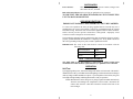
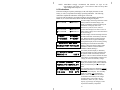
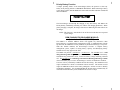
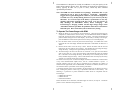
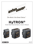
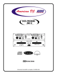
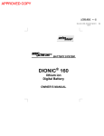
®
PowerCharger
DUAL and QUAD
2400 and 2700 series
OWNER’S MANUAL
TABLE OF CONTENTS
INTRODUCTION ............................................................................................. 1
STANDARD FEATURES................................................................................. 1
EXPANSION OPTIONS .................................................................................. 2
SAFEGUARDS ................................................................................................ 3
GROUNDING/EARTHING............................................................................... 3
FUSE TYPE/REPLACEMENT......................................................................... 3
OPERATION.................................................................................................... 3
Self-Test ....................................................................................................... 3
Charging....................................................................................................... 4
Applications .................................................................................................. 4
Three Stage Charging Methodology ............................................................ 5
LCD Indications ............................................................................................ 6
LED Indications ............................................................................................ 7
Priority Battery Function............................................................................... 8
DDM (DIAGNOSTIC/DISCHARGE MODULE)................................................ 8
To Operate The PowerCharger with DDM................................................... 9
“AUTOCAL” Feature .................................................................................. 10
XM CHARGE EXPANSION MODULE .......................................................... 11
OPERATION AS DC CAMERA SUPPLY FROM MAINS ............................. 11
POWER LOSS MEMORY MODE ................................................................. 12
FCC NOTICE................................................................................................. 12
WARRANTY .................................................................................................. 13
INTRODUCTION
This Anton/Bauer InterActive 2000 PowerCharger represents over 25 years of Anton/Bauer
technology and experience in a totally new portable power system. The technology
advancements of this new combination, charger/camera power supply, delivers the features
and performance of several essential power products in one economical package.
Fully compatible with all current and future Anton/Bauer Logic Series Gold Mount
batteries, the InterActive 2000 system is a totally new modular platform. PowerChargers
deliver all the advancements and proven reliability of InterActive charging, plus the ability
to power a camera from AC mains. Its unique modular design allows economical expansion
to meet future operational needs and technological developments.
Because the PowerCharger is completely software controlled, as new technology batteries
are introduced, the PowerCharger will merely require a new programming chip to charge the
new batteries along side your existing ones.
The unprecedented value and unique features of the InterActive 2000
PowerCharger system has redefined the standard of power for all video operations
- from individual videographers to the largest broadcast operation.
STANDARD FEATURES
• Two and Four Position models each with the full complement of InterActive
technologies including: six simultaneous charge termination systems, SSP (Selective
Sequence Programming), balance and rejuvenation mode, Lifesaver Maintenance
mode, Power Loss Memory mode.
• Multifunction LCD displays critical battery and charger data automatically.
• Regulated DC power supply output for camera operation from AC mains,
eliminating the need for a separate bulky power supply.
• Wide range mains input compatibility (90-250 VAC 50-60 Hz) automatically adapts
to any mains source worldwide.
• Modular design allows addition of expansion options.
• Expanded InterActive communications with DIGITAL batteries, anticipating new
cell technologies.
• Serial output port for printer and PC interface.
• Slim, ultra-lightweight design for easy portability. A four position PowerCharger fits
easily in a notebook computer carry case.
• Charge position expansion port for charging up to four additional batteries.
• Two power module choices for optimized performance and economy. Model series
2400 features a 40 watt power supply and Models 2700 feature a 70 watt power
supply. Model and rating can be confirmed in the Signature Display.
1
EXPANSION OPTIONS
The exclusive modular design of the new Anton/Bauer InterActive 2000 PowerCharger
provides ultimate flexibility for all video operations. Starting with any base model, a
wide range of expansion modules and upgrades can be added: diagnostic/discharge
functions, charge position expansion, and power supply modules. All this is as easy as
installing a memory or peripheral addition to a computer.
• Diagnostic/discharge module (DDM) featuring automatic calibration of DIGITAL
batteries. This also allows periodic diagnostic testing of any Logic Series battery. This
optional module is a standard feature of the QUAD 2702.
• Four position expansion module (XM 2004) allows charging of up to eight (8) Logic
Series Gold Mount batteries.
• Power Supply upgrade allows 40 watt models (2400 series) to be upgraded to 70
watt (2700 series) capability.
1------3------1
2
1
2
3
4
3
4
2------4-------
DISPLAY
TEST
1
2
1
2
3
4
3
4
FRONT
MAX. OUTPUT
70 WATTS
ANTON/BAUER
SHELTON, CT USA
(203) 929-1100
BACK
IMPORTANT: READ ALL INSTRUCTIONS, NOTES AND OPERATING
SPECIFICATIONS FULLY BEFORE OPERATING THIS
EQUIPMENT.
This unit was packaged at the factory to arrive intact at its destination. If there
is any damage to the packaging or the unit when received, please notify the
carrier immediately.
2
SAFEGUARDS
Power Sources:
This unit was designed to operate at mains voltages from
90 to 250 Volts AC, 50-60 Hz.
Risk of Electrical Shock: Refer servicing to qualified service personnel.
TO PREVENT FIRE OR SHOCK HAZARD, DO NOT EXPOSE THIS
UNIT TO RAIN OR MOISTURE.
GROUNDING/EARTHING
IMPORTANT WARNING: THIS APPARATUS MUST BE EARTHED.
To ensure safe operation, the three pin plug supplied must be inserted only into a
standard three-pin power point which is effectively grounded through the normal
household wiring. Extension cords used with the equipment must be three-conductor
and be correctly wired to provide connection to earth ground. Improperly wired
extension cords are a dangerous electrical hazard.
The fact that the equipment operates satisfactorily does not imply that the power point is
properly grounded and that the installation is completely safe. If any doubt exists about
the correct grounding of the power point, consult a qualified electrician.
IMPORTANT: The wires in this main lead are colored in accordance with the
following code:
Green and yellow
Earth
Blue
Neutral
Brown
Live
FUSE TYPE/REPLACEMENT
The mains input of the PowerCharger is fused using a printed circuit board
mounted device which should be replaced ONLY by a qualified service technician.
OPERATION
Self-Test
Upon applying mains power, each PowerCharger will initiate a self-test mode. This mode is
indicated in the LCD, by an audible alert and the lighting of each LED on the PowerCharger
(and any charge module attached) in sequence. Upon completion of the self-test, the green
status light will light steadily, indicating that the unit is ready for operation.
NOTE: Mount batteries to the charger or any charge expansion module attached only
when the PowerCharger has completed its self-test mode. Disconnect the
camera cable from the 4 Pin XLR Connector located on the back of the
PowerCharger.
3
Software revision, power rating, and model number can be obtained from the Signature
Display. When the LCD shows the main display screen, press the TEST button on the
front panel.
Charging
As with all Anton/Bauer chargers, charging with an InterActive 2000 PowerCharger is
fully automatic. Mount any applicable battery to any open Gold Mount position on the
charger or charge expansion module and the PowerCharger will automatically determine
the appropriate charge routine and execute it.
Applications
All PowerCharger models will charge any combination of Anton/Bauer Logic Series
Gold Mount batteries including models: ProPac 13/14, Compac 13/14, Trimpac 13/14,
Digital ProPac 13/14, Digital Compac 13/14, Digital Trimpac 13/14, InterActive 2000
HyTRON, and DIONIC batteries.
Each PowerCharger incorporates the exclusive Anton/Bauer InterActive
communication between battery and charger, which allows the charger to identify any
Anton/Bauer battery attached and determine the precise charge routine for that battery
under the prevailing conditions.
When coupled with Anton/Bauer DIGITAL batteries, the PowerCharger has
additional information supplied from the battery which includes:
• serial number of the battery
• the characteristics of the battery, including voltage, capacity and cell chemistry
• date of manufacture
• temperature of the battery
• number of charge and discharge cycles the battery has experienced
• amount of self-discharge the battery has experienced since last being charged
• “learned” capacity of the battery
This information is communicated to the charger by the battery and is incorporated,
through specialized programming and algorithms to optimize the charging of the
DIGITAL battery.
NOTE: Due to the specialized communications between the charger and the
battery, batteries without the Logic Series construction and
communication capability (manufactured by Anton/Bauer before 1989
as well as so-called “rebuilds”) can not be charged with this
PowerCharger.
The InterActive communication of Logic Series
batteries is the key which allows the PowerCharger to safely identify and
address new style and chemistry batteries as they are developed.
Moreover, this communication ensures that batteries contain the quality
cells, workmanship and safety of genuine Anton/Bauer products. If nonLogic Series batteries are placed on the PowerCharger, a message will
appear accompanied by alternating flashing red and green LED
indicators. This indication means that the battery cannot communicate
its identity to the PowerCharger and is not charging.
4
Three Stage Charging Methodology
In general, the PowerCharger will deliver a three stage charge routine to each
battery.
1. Stage One will deliver a high rate charge matched to the capabilities of the
battery (typically a one or two hour rate, depending on battery type and charger
power module rating). During this stage, six separate cutoff methods are in
operation, simultaneously, ensuring the fastest, safest charge for that battery.
Stage One is indicated by the LCD displaying “Charging (Primary)”.:
TCO - Temperature cutoff which stops the Stage one charge precisely when
a temperature indicative of full charge is reached;
Dt/dT - a microprocessor based algorithm which measures a rise in
temperature over a specific time, very accurately indicating full charge. This
method is also the recommended method for charging Ni-MH technology;
-ΔV - a method to determine the end of stage one charging by identifying a
characteristic “reverse slope” of a Ni-Cd cell. Since this characteristic can
be disguised by the age, temperature and the number of the cells in a battery,
it can never be employed alone;
CCO - this method requires the identification of the particular battery size
(capacity) and chemistry, an exclusive Anton/Bauer Logic Series feature.
The charger determines the maximum charge time for the particular battery
and uses this information to ensure that overcharge conditions are avoided.
FUL - this determination is made when a fully charged DIGITAL battery is
returned to a PowerCharger within specified parameters of time, temperature,
and battery voltage. The DIGITAL battery communicates its fully charged
condition and the charger confirms the parameters and immediately indicates a
fully charged condition, without additional verification.
TEMPERATURE COMPENSATED VCO – for HyTRON series of
batteries. Similar to a VCO, however, only operates within certain temperature
parameters.
2. Stage Two charging is a BALANCING or “equalize” mode which calculates each
battery pack type to offset any imbalance of the battery’s cells, created by unequal
self discharge or any capacity mismatch of the individual cells in the pack. This
stage can vary in duration from zero to as much as 16 hours, depending on the
condition of the battery. A battery will typically leave Stage Two in 2-4 hours
under average operating conditions. Stage Two is indicated by the LCD
displaying “Ready (Secondary)”.
3. Stage Three charging is the Anton/Bauer exclusive Lifesaver maintenance
mode. This patented pulse routine keeps batteries fully charged, free from selfdischarge - indefinitely - without damaging heat associated with so-called
“trickle charge”. Stage Three is indicated by the LCD displaying “Ready
(Lifesaver)”.
5
NOTE: Anton/Bauer strongly recommends that batteries are kept on the
PowerCharger until ready for use. The Lifesaver mode will keep them
100% charged and ready for use.
LCD Indications
Each PowerCharger’s liquid crystal display (LCD) will display the status of each
battery, as well as, important PowerCharger operating indications. The following
information explains the indications which appear in the LCD.
The levels of the LCD display on each PowerCharger can be obtained by pressing the
DISPLAY, or in some cases TEST, button on the PowerCharger front panel.
1-------
2-------
1------3-------
2------4-------
1—WAIT
3—CHARGE
2—READY
4—READY
DUAL 2701 Rev. #3.xx
Discharger NOT INSTALLED
1—Waiting to Charge
PROPAC 14
16.5 V
2—READY (Lifesaver)
4.0
PROPAC 14D 100% 16.5 V
2—Ser# 96280 Mar98 4.0
118 cycles
VCO 27oC
The Main Display shows the general status of each
battery mounted to the PowerCharger. This
display is immediately returned to following self
test and after viewing any other screen.
Both the two position (above) and four
position Main Displays will show a series of
dashes when a battery has not been mounted to
the PowerCharger.
The Main Display of the PowerCharger will show
the abbreviated status of each battery on the main
unit. Batteries mounted to a charge expansion
module (XM) will NOT appear in the display.
The Signature Display can be viewed by pressing
and holding the TEST button from the Main
Display on the PowerCharger to obtain model
information, Software revision number and
installation of DDM (discharger).
The Primary Position Display is obtained by
pressing the DISPLAY button repeatedly until
the position number for the battery desired is
displayed. This view further identifies the status
of the battery, its model number (chemistry and
voltage), as well as current battery voltage.
The Primary Position Display will additionally
display the available capacity when a DIGITAL
battery is used, both in percent and in ampere
hours.
The Secondary Position is obtained by pressing
and holding the DISPLAY button while viewing
the primary position display. This Secondary
display is available only with DIGITAL
batteries and is used to obtain information
transmitted from the battery to the charger
including battery serial number, date of
manufacture, number of cycles, “learned”
capacity, type of stage one charging cut-off
experienced and battery temperature.
6
LED Indications
Each charge position of a PowerCharger and PowerCharger Charge Module (XM
models) has a pair of LEDs (one red, one green) which indicate the status of the battery
attached to that position. The following table identifies all of the PowerCharger LED
indications and their meaning:
LED INDICATION
MEANING
Alternating
Red & Green
Indicates that the PowerCharger is evaluating the battery and/or
communicating with a DIGITAL battery, loading battery
parameters and determining the appropriate charge routine. A
low voltage (<11V) battery will cause this indication to continue
until the battery is “rejuvenated” to a safe charging voltage.
NOTE: This indication will continue if a non-Anton/Bauer Logic
Series battery is mounted on the charger. These batteries cannot
identify themselves to the PowerCharger and will not be charged.
Steady Red
Indicates that the battery is being held by the PowerCharger
EITHER in line to charge, to stabilize an out-of-range temperature
condition, or to await discharge in test mode with a DDM module
installed.
Flashing Red
Indicates that the battery is currently under Stage One chargeCharging (Primary).
Flashing Green
(slow rate)
Indicates that the battery is currently under Stage Two chargeReady (Secondary).
Flashing Green
(fast rate)
Indicates a fully charged DIGITAL battery is placed on the
charger and a FUL cutoff condition cannot be met. The charger
is VERIFYING that the battery is in a full charge condition.
Steady Green
Indicates that the battery is READY and in Stage Three Lifesaver
mode.
NOTE: In some cases, a battery may be discharged to a very low voltage level
at which the battery is unrecognizable to the charger when first
attached. In this case, no indications will appear on the LED (or LCD)
display. Each PowerCharger constantly looks for such batteries,
applying small, safe amounts of charge current to each empty charge
position. This search mode occurs whenever the charger is NOT
occupied in a Stage One mode on another position. If the charger is
otherwise busy, it will search only occasionally for such batteries and
the position may have no LED or LCD indication. This is normal.
The charger will properly identify and address the position when the
other batteries have completed Stage One.
7
Priority Battery Function
A unique operating feature of all PowerChargers allows the operator to select any
battery on any charge position as a PRIORITY BATTERY. While connecting a battery
to any charge position, hold the DISPLAY button until an audible indication sounds and
the LCD indicates:
PRIORITY BATTERY
The PowerCharger will interrupt the charging of any other battery and address the
Priority Battery immediately (assuming it is within a safe charging parameters). When
priority charging is complete, the charger will return to addressing the other batteries on
the charger.
NOTE: This function is unavailable if the AUTOCAL mode has been requested
by the charger.
DDM (DIAGNOSTIC/DISCHARGE MODULE)
(standard on Model QUAD 2702)
The DDM is a modular addition which will upgrade any InterActive 2000
PowerCharger to a complete battery management system. A standard feature with the
QUAD 2702, the DDM can be easily added to any model PowerCharger, at any time.
With this module installed, the PowerCharger becomes a complete battery
management system, capable of testing battery capacity and identifying battery
anomalies before they appear in the field.
The DDM will perform a standard or a 24 hour test. The standard test is a full
charge-discharge-full charge routine, which will identify the capacity of the battery
and indicate any performance issues, such as low battery voltage indicating a shorted
cell. The 24 hour test is a full charge-wait 24 hours-discharge-full charge routine
which will identify any excessive self-discharge or serious cell imbalance condition.
Test time will vary with battery condition and watt hour rating. The standard test will
require a minimum of 6 hours to a maximum of about 12 hours. The 24 hour test will
require an additional 24 hours as the battery undergoes a 24 hour rest time to identify
self-discharge anomalies. It is recommended that the 24 hour test be performed only on
weekends or when the battery is not scheduled to be used for 2-3 days.
8
The standard test is adequate for virtually all conditions to verify the capacity of the
battery before taking it into the field. The 24 hour test need only be performed on a
battery, typically an older one (2 years or more), which may have exhibited
questionable performance.
Note: The DDM test mode should be used sparingly. Remember that a cycle
performed in test is part of the battery’s overall life. Anton/Bauer
suggests that a typical management routine for your batteries might be to
test them once every 90 days during the first two years and every 60 days
thereafter. If a record is kept of the battery’s performance on test, any
anomaly will become apparent from the record. It is not necessary to
fully discharge an Anton/Bauer battery before recharging.
The
PowerCharger’s charging routines and the high voltage design of the
Anton/Bauer batteries precludes the problems which old 12 volt batteries
had in the past. Don’t waste battery life on unnecessary testing.
To Operate The PowerCharger with DDM
1. Mount the battery to any position on the PowerCharger. When the PowerCharger has
completed its communication with the battery, the ALTERNATING RED and GREEN
LEDs will stop and the battery will begin its charge routine. The battery information and
position number will appear on the LCD display. (If the battery is already on the charger,
press the DISPLAY button until the position for the battery to be tested is displayed.)
2. Press the TEST button on the front panel of the PowerCharger. An audible alert will be
heard and the LCD will display “HOLD TEST BUTTON 3 SECONDS TO SELECT A
TEST”.
3. Hold the TEST button as the unit beeps 3 times. Release the button and the unit will
indicate that the test mode has been selected. This Standard test will charge-dischargecharge the battery. Testing time is approximately 6-8 hours per battery.
4. The PowerCharger will ask if the 24 hour test is desired. If so, press the TEST button
again to select this test. If not, the PowerCharger will automatically begin the standard
test. A 24 Hour Test will charge the battery, let the battery sit for a 24 hour period, test the
battery and then charge the battery. This test will determine how much capacity the battery
will lose over a 24 hour period, when not being used.
The “RS-232 Accessory Port” on the PowerCharger transmits test information in ASCII format
to any serial communications capable device, such as a terminal emulator or printer. A
personal computer serial port can also be connected and by employing any number of
communications applications (such as PROCOMM, or Windows “Terminal”) test data can be
saved in file format as a permanent record of battery performance.
A serial data capable printer can be attached to the PowerCharger at the “RS-232 Accessory
Port”, enabling the printout of hard copy of performance data from a tested battery. The
following is a partial list of printer manufacturer models which are compatible with the
PowerCharger:
• Okidata ML 184 Turbo
• Okidata ML 395
• Panasonic KX-P3200
Printers should be set for 1200 baud, 8 bit data length, one start bit, one stop bit. Consult the
printer’s owners’ manual for setup instructions.
9
When testing is completed, the LCD Main Display will indicate “TEST DONE”. To
display or print test results:
1. Press the DISPLAY button on the PowerCharger front panel to scroll to the
Primary Position Display for the battery tested.
2. Press the TEST button. The LCD will display the capacity of the battery in
ampere hours. If a printer is attached, performance data will simultaneously be
printed out with all battery identification information. Consult your battery
owners manual for warranty information and cell capacity ratings.
Remove battery only when test data has been viewed or printed. Test data is retained
only while the battery is on the PowerCharger. Once battery is removed, data is no
longer available.
“AUTOCAL” Feature
When a DDM is installed in the PowerCharger, a special InterActive mode is
automatically enabled for DIGITAL batteries placed on the PowerCharger at any
time. The PowerCharger will interrogate the status of the DIGITAL battery to
determine whether the battery has received a “learning” cycle or “calibrate” cycle
within certain parameters. This “learning” typically occurs in normal equipment
operation, however, if the battery has not been fully charged and discharged in some
time, a “double arrow” or “calibrate” indication will appear on the battery. The
DIGITAL battery will continue to function normally with this indication. It is a
request by the battery to fully charge and discharge the battery to the “EOD” point at
the next opportune time so that the battery can verify its capacity. See DIGITAL
battery Owner’s Manual for complete description of this indication.
The PowerCharger with DDM will detect a request from the DIGITAL battery and
automatically enter an AUTOCAL mode when the battery is placed on the charger.
This mode is indicated by the PowerCharger with an audible alert and a message in
the LCD advising that the AUTOCAL routine has been called. This mode can be
canceled, for example, if time constraints do not allow for the test to be completed.
The mode is identical to the charge-discharge-charge previously described.
The AUTOCAL mode can be canceled by following the prompts appearing in the
LCD, using the TEST button to cancel the test. If the test is not canceled, it will
commence automatically.
When the AUTOCAL operation is complete, the battery will be fully charged and
ready for use.
10
XM CHARGE EXPANSION MODULE
The “XM” charge expansion modules easily attach to any model PowerCharger via the 9pin D-shell computer style connector marked “CHARGE MODULE ACCESSORY”.
These economical modules automatically expand the PowerCharger’s charging
capabilities with additional positions. The XM-2002 or XM-2004 modules allow the
charging of two or four additional Logic Series batteries. The XM NP/90 module will
charge any combination of up to four NP or 90 style batteries. The XM charge modules
are “slaves” to the host PowerCharger, that is, they receive all their operating capabilities
from the PowerCharger.
The XM charge expansion modules employ all the advanced InterActive 2000
charging features of the PowerChargers. The LED indications are identical to the
ones previously described for the PowerCharger “host”. However, XM modules will
not display information in the PowerCharger LCD, although the modules are in
communication with the batteries. Also, batteries on the XM modules cannot be
tested with the DDM. To obtain battery information or to run a performance test,
move batteries to the “host” PowerCharger.
OPERATION AS DC CAMERA SUPPLY FROM MAINS
Each PowerCharger model can operate cameras and camcorders using the four pin
camera output connector located at the back of the PowerCharger. To power the camera,
attach one end of the XLR4 accessory cable (available separately) to the PowerCharger.
Attach the other end to the “DC in” four pin XLR on the camera/camcorder. Disconnect
the charge module accessory from the PowerCharger. Move the switch located next to
the connector to the “CAMERA” position. A message will appear in the PowerCharger
LCD:
CAMERA POWER MODE IS ON
BATTERIES NOT CHARGING
The PowerCharger will remember the point at which it left its charge routine for any
battery on the charger. When the switch is returned to the “CHARGER” position, the
batteries will automatically continue charging where they left off.
During camera operation, with batteries on the PowerCharger, the unit will indicate a
flashing GREEN LED for any battery position which is more than 50% charged.
Batteries less the 50% charged will have no indication.
Application Note: Model 2400 series DUAL and QUAD PowerChargers feature a 40
watt maximum output for camera powering. The Model 2700 DUAL and QUAD
PowerChargers have a maximum 70 watts output. It should be noted that, in general,
due to camera turn-on surges, operation of zoom lenses and tape ejection mechanisms
that the 2700 series PowerChargers should be used on equipment with operating
specifications of more than 25 watts.
11
POWER LOSS MEMORY MODE
The PowerCharger features a special Power Loss Memory or “Power Down” mode.
When mains power is interrupted while batteries are mounted, the PowerCharger will
automatically indicate the charge status of all batteries until power is restored (up to 16
hours). When power is interrupted, an audible alert will be heard every 30 seconds for
30 minutes to notify the operator if power has been inadvertently removed. The LCD
will display the message “POWER DOWN MODE” along with a counter which will
indicate time since mains power has been lost.
During “POWER DOWN MODE”, batteries more than 50% charged will be
indicating by a flashing RED LED. Batteries fully charged will be indicated by a
POWER DOWN
00:00:00
flashing GREEN LED. A battery less than 50% charged will show no indication.
When AC power is restored, the PowerCharger will automatically replenish the
power taken from the batteries during Power Down and resume charging each battery
in the mode and order when mains power was interrupt.
FCC NOTICE
This equipment has been tested and found to comply with the limits for a Class A
digital device pursuant to Part 15 of the FCC Rules. These limits are designed to
provide reasonable protection against harmful interference when the equipment is
operated in a commercial environment. This equipment generates, uses, and can
radiate radio frequency and, if not installed and used in accordance with the
instruction manual, may cause harmful interference to radio communications.
Operation of this equipment in a residential area is likely to cause harmful
interference in which case the user will be required to correct the interference at his
own expense.
This equipment has been approved by one or more agencies. All changes and/or
modifications not expressly approved by Anton Bauer, Inc. could void the users’
warranty and authority to operate this equipment. There are no serviceable parts in
this equipment.
12
WARRANTY
IMPORTANT: PLEASE MAIL WARRANTY REGISTRATION CARD WITHIN
TEN (10) DAYS OF PURCHASE. We must have this card on file at our SERVICE
DEPARTMENT to establish this warranty. Proper registration will also enable us to
provide update information on the InterActive 2000 PowerCharger battery system.
All new Anton/Bauer products have been thoroughly tested and inspected prior to
shipment. This product is warranted against defect in materials and workmanship for
a period of three (3) years from date of purchase. If this product fails to perform to
its specifications during this period, it will be repaired or replaced at Anton/Bauer’s
option. This Warranty does not cover damage resulting from accident, misuse,
neglect, or improper service or maintenance. Use of unauthorized service
replacement parts or attachments will void this Warranty. Misuse includes any use of
this product in other than its intended applications. No responsibility is assumed for
any special, incidental or consequential damages. No other Warranty, written, oral or
implied is assumed or authorized by Anton/Bauer. The liability of Anton/Bauer
hereunder is expressly limited to a claim for a repair or replacement for the goods
sold or as otherwise stated herein.
This Warranty is to be construed and enforced in accordance with the law of the State
of Connecticut, including the provisions of the Uniform Commercial Code as adopted
and, from time to time, amended in the State of Connecticut and not the Convention
for the International Sale of Goods. This choice of Connecticut law is exclusive of
any Connecticut law that would require reliance on any low foreign to Connecticut.
Should any action of law or in equity be brought by any person under this Warranty,
such action shall be brought only in the United States District Court for the District of
Connecticut, or in any Superior Court in Fairfield County, Connecticut, U.S.A.
If you have any questions regarding applications or specifications, or to obtain
warranty service on this or any Anton/Bauer product, contact the Anton/Bauer
Customer Support Group. See back page for contact information.
13
The worldwide standard
®
®
The power behind the best cameras capturing the best images in the world.sm
The following are trademarks of Anton/Bauer, Inc.:
ACS, ADM, Anton/Bauer, Anton/Bauer logo and parallelogram design, Aspekt,
Automatique, DataTap, Dionic, ElipZ, ElightZ, EgripZ, Gold Mount, HyTRON,
Impac, InterActive and design, LifeSaver, Logic Series, Logic Series logo, Maxx man
logo design, MicroCode, PowerStrap, Probe, Proformer, ProPac, RealTime, SSP,
Satellight, Snap-On, Stasis, Tandem, TrimPac, Ultrakit, Ultralight, “The power
behind the best cameras capturing the best images in the world”, “The quality
standard of the video industry”, “The worldwide standard”, and “There should always
be choices. It makes it easier to recognize the best”.
Anton/Bauer, Inc.
Anton/Bauer Europe, B.V.
World Headquarters
14 Progress Drive, Shelton, CT U.S.A.
Tel (203) 929-1100 or (800) 541-1667
Fax (203) 929-9935
[email protected]
Eurode Business Center, Eurode - Park 1
6461KB Kerkrade, The Netherlands
Tel +31 45-563-9220
Fax +31 45-563-9222
[email protected]
www.antonbauer.com
7595-0112 Rev G