1
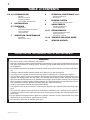
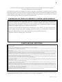
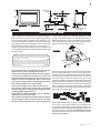
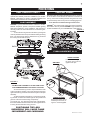
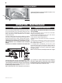
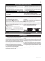
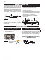
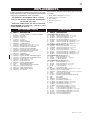
1
INSTALLER: LEAVE THIS MANUAL WITH THE APPLIANCE.
CONSUMER: RETAIN THIS MANUAL FOR FUTURE REFERENCE.
NEVER LEAVE CHILDREN OR OTHER AT RISK INDIVIDUALS ALONE WITH THE APPLIANCE.
INSTALLATION AND
OPERATING INSTRUCTIONS
CERTIFIED UNDER CANADIAN AND AMERICAN NATIONAL STANDARDS: CSA 2.22, ANSI Z21.50 FOR VENTED GAS FIREPLACES.
CERTIFIED FOR CANADA AND UNITED STATES USING ANSI/CSA METHODS.
SAFETY INFORMATION
!
WARNING
If the information in these instructions
are not followed exactly, a fire or
explosion may result causing property
damage, personal injury or loss of life.
- Do not store or use gasoline or other flammable
vapors and liquids in the vicinity of this or any
other appliance.
- WHAT TO DO IF YOU SMELL GAS:
•
Do not try to light any appliance.
•
Do not touch any electrical switch; do not use
any phone in your building.
•
Immediately call your gas supplier from a
neighbour’s phone. Follow the gas supplier’s
instructions.
•
If you cannot reach your gas supplier, call the
fire department.
- Installation and service must be performed by a
qualified installer, service agency or the supplier.
This appliance may be installed in an aftermarket,
permanently located, manufactured home (USA
only) or mobile home, where not prohibited by
local codes.
This appliance is only for use with the type of gas
indicated on the rating plate. This appliance is
not convertible for use with other gases, unless a
certified kit is used.
CBI 360 - N
NATURAL GAS
CBI 360 -P
PROPANE
!
WARNING
HOT GLASS WILL CAUSE
BURNS.
DO NOT TOUCH GLASS UNTIL
COOLED.
NEVER ALLOW CHILDREN TO
TOUCH GLASS.
Wolf Steel Ltd., 24 Napoleon Rd., Barrie, ON, L4M 0G8 Canada /
103 Miller Drive, Crittenden, Kentucky, USA, 41030
Phone (705)721-1212 • Fax (705)722-6031 • www.continentalfireplaces.com • [email protected]
$10.00
1.31A
W415-0120 / F / 10.25.11
2
TABLE of CONTENTS
PG 2-5 INTRODUCTION
8
Warranty
General Instructions
General Information
Care of Glass, & Plated Parts
5
CONT'D
Operating Instructions
Maintenance
9
BLOWER SYSTEM
Blower Replacement Instructions
INSTALLATION
9
6-7 FINISHING
ADJUSTMENTS
Pilot Burner Adjustment
Venturi Adjustments
Brick panels
Log Placement/Charcoal Embers
Louvre Installation
Logo Placement
7
OPERATION / MAINTENANCE
10-11 REPLACEMENTS
Ordering Replacement Parts
Replacement Parts
Accessories / Options
OPERATION / MAINTENANCE
Spill Switch
Venting Action Check
12-13 TROUBLE SHOOTING GUIDE
14
SERVICE HISTORY
PLEASE RETAIN THIS MANUAL FOR FUTURE REFERENCE
WARNING
• Do not burn wood or other materials in this fireplace.
• Adults and especially children should be alerted to the hazards of high surface temperatures and should
stay away to avoid burns or clothing ignition. Supervise young children when they are in the same room
as the fireplace.
• Due to high temperatures, the fireplace should be located out of traffic and away from furniture and draperies.
• Clothing or other flammable material should not be placed on or near the fireplace.
• Any safety screen or guard removed for servicing must be replaced prior to operating the fireplace.
• It is imperative that the control compartments, burners and circulating blower and its passageway in the
fireplace and venting system are kept clean. The fireplace and its venting system should be inspected
before use and at least annually by a qualified service person. More frequent cleaning may be required
due to excessive lint from carpeting, bedding material, etc. The fireplace area must be kept clear and free
from combustible materials, gasoline and other flammable vapours and liquids.
• Under no circumstances should this fireplace be modified.
• This fireplace must not be connected to a chimney flue pipe serving a separate solid fuel burning appliance.
• Do not use this fireplace if any part has been under water. Immediately call a qualified service technician
to inspect the fireplace and to replace any part of the control system and any gas control which has been
under water.
• Do not operate the fireplace with the glass door removed, cracked or broken. Replacement of the glass
should be done by a licensed or qualified service person.
• Do not strike or slam shut the fireplace glass door.
W415-0120 / F / 10.25.11
3
CONTINENTAL gas fireplaces are manufactured under the strict Standard of the world recognized
ISO 9001 : 2000 Quality Assurance Certificate.
CONTINENTAL products are designed with superior components and materials, assembled by trained craftsmen
who take great pride in their work. The burner and valve assembly are leak and test-fired at a quality test station. The
complete fireplace is thoroughly inspected by a qualified technician before packaging to ensure that you, the customer,
receives the quality product that you expect from CONTINENTAL.
CONTINENTAL GAS FIREPLACE PRESIDENT'S LIFETIME LIMITED WARRANTY
The following materials and workmanship in your new CONTINENTAL gas fireplace are warranted against
defects for as long as you own the fireplace. This covers: combustion chamber, heat exchanger, stainless steel
burner, phazer™ logs and embers, ceramic glass (thermal breakage only), gold plated parts against tarnishing,
porcelainized enamelled components and aluminum extrusion trims.
Electrical (110V and millivolt) components and wearable parts such as blowers, gas valves, thermal switch,
switches, wiring, remote controls, ignitor, gasketing, and pilot assembly are covered and WOLF STEEL LTD.
will provide replacement parts free of charge during the first year of the limited warranty.
Any labour related to warranty repair is not covered.
CONDITIONS AND LIMITATIONS
CONTINENTAL warrants its products against manufacturing defects to the original purchaser only -- i.e., the individual or legal entity (registered customer) whose name appears
on the warranty registration card filed with CONTINENTAL -- provided that the purchase was made through an authorized CONTINENTAL dealer and is subject to the following
conditions and limitations:
This factory warranty is nontransferable and may not be extended whatsoever by any of our representatives.
The gas fireplace must be installed by a licenced, authorized service technician or contractor. Installation must be done in accordance with the installation instructions included
with the product and all local and national building and fire codes.
This limited warranty does not cover damages caused by misuse, lack of maintenance, accident, alterations, abuse or neglect and parts installed from other manufacturers will
nullify this warranty.
This limited warranty further does not cover any scratches, dents, corrosion or discolouring caused by excessive heat, abrasive and chemical cleaners nor chipping on porcelain
enamel parts, mechanical breakage of PHAZER™ logs and embers, nor any venting components used in the installation of the fireplace.
CONTINENTAL warrants its stainless steel burners against defects in workmanship and material for life, subject to the following conditions: During the first 10 years CONTINENTAL will replace or repair the defective parts at our option free of charge. From 10 years to life, CONTINENTAL will provide replacement burners at 50% of the current retail price.
In the first year only, this warranty extends to the repair or replacement of warranted parts which are defective in material or workmanship provided that the product has been
operated in accordance with the operation instructions and under normal conditions.
After the first year, with respect to this President's Limited Lifetime Warranty, CONTINENTAL may, at its discretion, fully discharge all obligations with respect to this warranty by
refunding to the original warranted purchaser the wholesale price of any warranted but defective part(s).
After the first year, CONTINENTAL will not be responsible for installation, labour or any other costs or expenses related to the reinstallation of a warranted part, and such expenses
are not covered by this warranty.
Notwithstanding any provisions contained in this President's Limited Lifetime Warranty, CONTINENTAL’S responsibility under this warranty is defined as above and it shall not in
any event extend to any incidental, consequential or indirect damages.
This warranty defines the obligations and liability of CONTINENTAL with respect to the CONTINENTAL gas fireplace and any other warranties expressed or implied with respect
to this product, its components or accessories are excluded.
CONTINENTAL neither assumes, nor authorizes any third party to assume, on its behalf, any other liabilities with respect to the sale of this product. CONTINENTAL will not be responsible for: over-firing, downdrafts, spillage caused by environmental conditions such as rooftops, buildings, nearby trees, hills, mountains, inadequate vents or ventilation, excessive
venting configurations, insufficient makeup air, or negative air pressures which may or may not be caused by mechanical systems such as exhaust fans, furnaces, clothes dryers, etc.
Any damages to fireplace, combustion chamber, heat exchanger, brass trim or other component due to water, weather damage, long periods of dampness, condensation, damaging
chemicals or cleaners will not be the responsibility of CONTINENTAL.
The bill of sale or copy will be required together with a serial number and a model number when making any warranty claims from your authorized dealer. The warranty registration
card must be returned within fourteen days to register the warranty.
CONTINENTAL reserves the right to have its representative inspect any product or part thereof prior to honouring any warranty claim.
ALL SPECIFICATIONS AND DESIGNS ARE SUBJECT TO CHANGE WITHOUT PRIOR NOTICE DUE TO ON-GOING PRODUCT IMPROVEMENTS. CONTINENTAL® IS A REGISTERED TRADEMARK OF WOLF STEEL LTD. PATENTS U.S. 5.303.693.801 - CAN. 2.073.411, 2.082.915. © WOLF STEEL LTD.
W415-0120 / F / 10.25.11
4
GENERAL INSTRUCTIONS
THIS GAS FIREPLACE SHOULD BE INSTALLED AND SERVICED BY A QUALIFIED INSTALLER to conform with local
codes. Installation practices vary from region to region and
it is important to know the specifics that apply to your area,
for example: in Massachusetts State:
• The fireplace damper must be removed or welded in the open
position prior to installation of a fireplace insert or gas log.
• The appliance off valve must be a “T” handle gas cock.
• The flexible connector must not be longer than 36 inches.
• The appliance is not approved for installation in a bedroom or
bathroom unless the unit is a direct vent sealed combustion
product.
• WARNING: This product must be installed by a licensed
plumber or gas fitter when installed within the commonwealth
of Massachusetts.
In absence of local codes, install to the current National
Fuel Gas Code, ANSI Z223.1, or the current CAN/CGA
B149, Installation Codes.
Purge all gas lines with the glass door of the fireplace removed. Assure that a continuous gas flow
is at the burner before installing the door.
Under extreme vent configurations, allow several
minutes (5-15) for the flame to stabilize after ignition.
Altitudes greater than 4000ft. require a minimum
vent run of 12ft.
The fireplace and its individual shutoff valve must be disconnected from the gas supply piping system during any pressure
testing of that system at test pressures in excess of 1/2 psig
(3.5 kPa). The fireplace must be isolated from the gas supply
piping system by closing its individual manual shutoff valve
during any pressure testing of the gas supply piping system
at test pressures equal to or less than 1/2 psig (3.5 kPa).
A 1/8 inch NPT plug, accessible for test gauge connection,
must be installed immediately upstream of the gas supply
connection to the stove.
This fireplace must be connected to any accepted lined chimney system listed to ULC-S635M (in Canada) or UL-1777 (in
USA). The venting connection must be in compliance with the
vent manufacturers installation instructions.
The draft hood must be installed so it is in the same atmospheric pressure zone as the combustion air inlet to the
fireplace.
Provide adequate ventilation and combustion air. Provide
adequate accessibility clearance for servicing and operating the fireplace. Never obstruct the front opening
of the fireplace.
This insert must be recessed into a vented noncombustible
woodburning fireplace (prefabricated or masonry) only.
The minimum fireplace size in which the heater is to be
installed is:
HEIGHT 17½ inches WIDTH 25½ inches DEPTH 16½
inches
The minimum distance, from the bottom of a combustible
mantle projecting 6" maximum from the wall to the top of the
unit, is 8".
W415-0120 / F / 10.25.11
The fireplace, when installed, must be electrically connected
and grounded in accordance with local codes. In the absence
of local codes, use the current CSA C22.1 CANADIAN ELECTRICAL CODE in Canada or the ANSI/NFPA 70 NATIONAL
ELECTRICAL CODE in the United States. The blower power
cord must be connected into a properly grounded receptacle.
The grounding prong must not be removed from the cord plug.
GENERAL INFORMATION
FOR YOUR SATISFACTION, THIS FIREPLACE HAS BEEN
TEST-FIRED TO ASSURE ITS OPERATION AND QUALITY! Maximum input is 24,000 BTU/hr for natural gas and
22,000 BTU/hr for propane. When the fireplace is installed
at elevations above 4,500ft, and in the absense of specific
recommendations from the local authority having jurisdiction,
the certified high altitude input rating shall be reduced at the
rate of 4% for each additional 1,000ft. Maximum output for
natural gas is 15,900 BTU/hr and 16,000 BTU/hr for propane.
Minimum inlet gas supply pressure is 4.5 inches water column
for natural gas and 11 inches water column for propane. This
fireplace is certified for bedroom and bedsitting room installation. Maximum inlet gas pressure is 7 inches water column for
natural gas and 13 inches water column for propane. Manifold
pressure under flow conditions is 3.5 inches water column for
natural gas and 10 inches water column for propane.
No external electricity (110 volts or 24 volts) is required
for the gas system operation.
Expansion / contraction noises during heating up and cooling
down cycles are normal and to be expected. Change in flame
appearance from "HI" to "LO" is more evident in natural gas
than in propane.
CARE OF GLASS AND PLATED
PARTS
Do not use abrasive cleaners to clean plated parts. Buff lightly
with a clean dry cloth. The glass is 3/16" ceramic glass available from your CONTINENTAL / Wolf Steel Ltd. dealer. Do
not substitute materials. Clean the glass after the first 10
hours of operation with a recommended gas fireplace glass
cleaner. Thereafter clean as required.
Do not clean glass when hot! If the glass is not kept clean
permanent discolouration and / or blemishes may result.
5
EXHAUST
(3"DIA)
7”
18 1/2”
27 1/2”
(30 1/2”)
17 1/2”
13 1/2”
22”
17 1/4”
2 1/2”
8"
43”
(49”)
GAS INLET
3”
ELECTRICAL INLET
LEFT SIDE
25”
30 1/8”
FIGURE 1
INSTALLATION
Clean out ashes from the inside of the wood-burning fireplace.
Make sure that the chimney and wood-burning fireplace
are in a clean and sound condition and constructed of noncombustible materials. If necessary have any repair work done
by a qualified person before installing the insert. Remove the
existing fireplace damper or lock into an open position.
Using screws, attach the fireplace warning tag (W385-0199)
to the inside of the firebox of the fireplace into which the insert
is being installed.
Line the chimney with a 3" or 4" diameter approved liner. With
a 4" liner, an increaser must be connected between the dilution
draft hood and the liner. Chimney installation must conform to
both national and local code requirements. The liner must be
continuous from the fireplace to the chimney cap.
FIGURE 2
DILUTION DRAFT
HOOD
WARNING: THIS FIREPLACE HAS BEEN CONVERTED FOR USE WITH A GAS FIREPLACE
INSERT ONLY AND CANNOT BE USED FOR BURNING WOOD OR SOLID FUELS UNLESS
ALL ORIGINAL PARTS HAVE BEEN REPLACED AND THE FIREPLACE IS RE-APPROVED BY
THE AUTHORITY HAVING JURISDICTION.
ATTENTION: CE FOYER A ETE CONVERTI AFIN D'ETRE UTILISE SEULEMENT COMME
FOYER ENCASTRE AU GAZ ET NE PEUT ETRE UTILSE POUR BRULER DU BOIS OU TOUT
AUTRE COMBUSTIBLE SOLIDE, SANS QUE TOUTES LES PIECES ORIGINALES AIENT ETE
REMPLACEES ET QUE LE FOYER SOIT APPROUVE DE NOUVEAU PAR LES AUTORITES
AYANT JURIDICTION.
W385-0199
The sheet-metal parts of the fireplace, in which the gas
fireplace insert is to be installed, must not be cut.
If the wood-burning factory-built fireplace has no gas access hole(s) provided, an access hole of 1½ inch or less
may be drilled through the lower sides or bottom of the
fireplace in a proper workman like manner. This access
hole must be plugged with non-combustible insulation
after the gas supply line has been installed.
Ensure that existing chimney cleanouts fit properly.
The refractory, glass doors, screen rails, screen mesh
and log grates may be removed from the fireplace before
installing the gas fireplace insert.
Smoke shelves, shields and baffles may be removed if
attached by mechanical fasteners.
The ventilation openings in the fireplace may be obstructed by the backer plates, aluminium trim etc. but these
parts are not to be applied so as to have an airtight seal.
DILUTION
PLATE
SECURING
CLIPS
Remove the securing screw from the front of the dilution plate.
Push the dilution draft hood out of the securing clips and attach the liner using 3 screws equally spaced. Pack insulation
around the liner at the damper area to prevent air flow from
entering the chimney. Move the insert into the centre of the
woodburning fireplace making sure that the dilution draft hood
inserts back into its securing clips. Level using the four leveling
screws located front and back on either side of the fireplace
base. Leveling the insert will eliminate rocking or excessive
noise when the fan is in operation. Replace the securing screw
to the front of the dilution plate.
FIGURE 3
Install rigid black pipe, a flex connector, if local codes permit,
or 1/2" type L, copper tubing with a 3/8" to 1/2" adapter and a
shut off valve to the fireplace. Seal and tighten securely. The
adapter will be required between the gas valve and the copper tubing or flex connector. Do not kink flexible connector!
Check for gas leaks by brushing on a soap and water solution.
Do not use open flame!
W415-0120 / F / 10.25.11
6
An on/off switch has been included and can be located at
the right side trim. For ease of accessibility, this switch may
be replaced with a wall switch or substituted with a millivolt
thermostat that may be installed in a convenient location on
any wall. Route a 2 strand solid core millivolt wire through the
electrical hole located at the bottom right side of the unit. The
recommended maximum lead length depends on wire size:
WIRE SIZE
MAX. LENGTH
14gauge
100 feet
16gauge
60 feet
18gauge
40 feet
The insert can be equipped with a flashing kit to close off
most fireplace openings. Mount the flashing inside the unit's
outer shell using 4 securing screws. The flashing and trim are
available in many finishes to accent any room decor. Objects
placed in front of the fireplace should be kept a minimum of
48" away from the front face.
Attach the two leads to terminals 1 and 3 located on the gas
valve.
FIGURE 4
1
2
3
FIGURE 5
Do not connect the gas valve to electricity (110 volts or
24 volts).
W415-0120 / F / 10.25.11
7
FINISHING
FIBRE FIREBRICK PANELS
CHARCOAL EMBERS
To give your insert that authentic masonry fireplace look,
optional fibre firebrick panels are available at your CONTINENTAL / Wolf Steel Ltd. dealer. Complete installation and
maintenance instructions are included with the kit.
Randomly place the embers beneath the front log, covering
all of the burner area beneath the hollowed out section of
the log. Place the remaining embers along the front. Keep
ember dust away from burner ports to avoid plugging them.
LOG PLACEMENT
Fine dust found in bottom of bag not to be used.
TM
PHAZER logs and charcoal embers, exclusive to CONTINENTAL Fireplaces, provide a unique and realistic glowing
effect that is different in every installation. Take the time to
carefully position the charcoal embers for a maximum glowing effect.
1. Place the front log onto the main burner, pushing it as
close as possible to the burner ports without blocking/covering
them. The left and right spacing between the log ends and
the burner ports should be equal.
PHAZERTM logs and charcoal embers glow when exposed to
direct flame. Use only certified PHAZERTM logs and charcoal
embers available from your CONTINENTAL / Wolf Steel Ltd.
FIGURE 7
BACK LOG
FLUSH LOUVRE KIT, GI-1L
LEFT
LOG
CENTER
LOG
RIGHT
LOG
SIDE VIEW
UPPER LOUVRES
Insert the back edge of
the upper louvre into the
upper louvre clips.
SIDE VIEW
UPPER
LOUVRE
FRONT LOG
LOUVRE
CLIP
CHARCOAL
EMBERS
FIGURE 6
YOU MAY FIND IT EASIER TO PLACE SOME CHARCOAL EMBERS BENEATH THE FRONT LOG NOW.
2. Place the back log onto the step located at the back
of the combustion chamber. The notch situated at the lower
right of the back log should be centered evenly above the pilot
assembly.
3. While supporting the back log, to prevent it from falling forward, set the three smaller logs into the pockets and
grooves of the front and back logs, respectively.
Log colours may vary. During the initial use of the fireplace,
the colours will become more uniform as colour pigments burn
in during the heat activated curing process.
POSITIONING THE LOGS
IMPROPERLY WILL CAUSE FLAME
IMPINGEMENT AND CARBONING.
LOWER LOUVRES
Secure the lower louvre
assembly to the insert, using the 4 screws supplied.
W415-0120 / F / 10.25.11
8
LOGO PLACEMENT
Remove the backing of the logo supplied and place on the
glass viewing area, as indicated.
13/8"
LOGO
FIGURE 9
11/8"
OPERATION / MAINTENANCE
SPILL SWITCH
VENTING ACTION CHECK
This is a thermally activated switch, attached to the back of
the unit and extending up into the dilution draft hood, which
senses the change in temperature and shuts down the gas
valve in the event of a severe downdraft of air or a blocked
or disconnected vent.
It acts as a safety shut-off to prevent a build up of carbon
monoxide or an explosion of unburnt gases during start up. If
the flue is blocked or has no "draw", the spill switch will automatically shut off the supply of gas within about 5-10 minutes.
TAMPERING WITH THE SWITCH CAN RESULT IN CARBON MONOXIDE (CO) POISONING AND POSSIBLE
DEATH.
A CHECK FOR CORRECT VENTING ACTION MUST BE
MADE BEFORE THE INSTALLED INSERT IS LEFT WITH
THE CUSTOMER.
Test after installing the unit into a vented non-combustible
fireplace in the following manner:
1. Close all doors and windows in the room; start exhaust
fans in the home; turn fireplace blower off.
2. Set controls to "high" and light the unit.
3. Wait 5 minutes. Light a match and hold it to the spill tube
opening.
4. Venting action is satisfactory if smoke is drawn into the spill
tube. Venting action is unsatisfactory if the flame and smoke
are not drawn into the tube.
5. If venting action is unsatisfactory, turn the unit off, wait
10 minutes and try again. If the smoke or flame is still not
drawn into the spill tube, turn the unit off and check for vent
blockage or restriction. If necessary, consult with a qualified
air quality specialist.
When lit for the first time, the fireplace will emit a slight
FIGURE 10
odour for a few hours. This is a normal temporary condition caused by the curing of the logs and the "burn-in" of
internal paints and lubricants used in the manufacturing
process and will not occur again. Simply open a window
to sufficiently ventilate the room.
After extended periods of non-operation such as follow-
W415-0120 / F / 10.25.11
ing a vacation or a warm weather season, the fireplace
may emit a slight odour for a few hours. This is caused
by dust particles in the heat exchanger burning off. Open
a window to sufficiently ventilate the room.
9
FOR YOUR SAFETY READ BEFORE LIGHTING:
A This fireplace has a pilot which must be lit by hand while
do not try to repair it. Call a qualified service technifollowing these instructions exactly.
cian. Force or attempted repair may result in a fire or
B Before lighting, smell all around the fireplace area for gas
explosion.
and next to the floor because some gas is heavier than air D Do not use this fireplace if any part has been under water.
and will settle on the floor.
Immediately call a qualified service technician to inspect
C Use only your hand to push in or turn the gas control knob.
the unit and replace any part of the control system and
Never use tools. If the knob will not push in or turn by hand,
any gas control touched by water.
WHAT TO DO IF YOU SMELL GAS:
• Immediately call your gas supplier from a neighbour's
• Do not try to light any appliance.
phone. Follow the gas supplier's instructions.
• Do not touch any electrical switch; do not use any phone
• If you cannot reach your gas supplier, call the fire departin your building.
ment.
LIGHTING INSTRUCTIONS
1.Stop! Read all the safety information above. When lighting
and re-lighting, the gas knob cannot be turned from "pilot" to
"off" unless the knob is depressed.
2.Turn off all electrical power to the stove.
3.Turn the gas knob
clockwise to off.
4.Wait 5 minutes for any gas in the combustion chamber to
escape. Continue to the next step if you do NOT smell any
gas. If you smell gas, STOP! and follow the instructions in
"What to do if You Smell Gas" listed above.
5.If the unit is equipped with a flame adjustment valve, turn
clockwise to off.
6.Locate the pilot situated in front of the rear log.
7.Turn the gas knob
counter-clockwise to "pilot" position.
8.Depress and hold
the gas knob while lighting the
pilot with the push
button ignitor. Keep the knob fully
depressed for one (1) minute, then release. If the pilot does
not continue to burn, repeat steps 3 through 7.
9.With the pilot lit, turn the gas knob counter-clockwise to
"on" position.
10.If your insert is equipped with a flame adjustment valve,
push and turn the knob to "high".
11.If your insert is equipped with a remote "on-off" switch, the
main burner may not come on when you turn the gas valve
to "on" or "high". The remote switch must be in the "on"
position as well to ignite the main burner.
12.Turn on all electrical power to the insert.
TO TURN OFF GAS
1.Turn off all electrical power to the unit if service is to be
performed.
2.Push in gas control knob slightly and turn
to off. DO NOT FORCE.
clockwise
MAINTENANCE
TURN OFF THE GAS AND ELECTRICAL POWER
BEFORE SERVICING THE FIREPLACE.
CAUTION: Label all wires prior to disconnection when servicing controls. Wiring errors can cause improper and dangerous
operation. Verify proper operation after servicing. This insert
and its venting system should be inspected before use and
at least annually by a qualified service person. The fireplace
area must be kept clear and free of combustible materials,
gasoline or other flammable vapours and liquids. The flow of
combustion and ventilation air must not be obstructed.
1. In order to properly clean the burner and pilot assembly,
remove the logs to expose both assemblies.
2. Keep the control compartment, logs, burner, air shutter
opening and the area surrounding the logs clean by vacuuming or brushing, at least once a year.
3. Check to see that all burner ports are burning. Clean out
any of the ports which may not be burning or are not burning
properly.
4. Check to see that the pilot flame is large enough to engulf
the thermopile on one leg and reaches toward the burner on
the other leg.
5. Replace the cleaned logs.
6. Check to see that the main burner ignites completely on
all openings when the gas knob for the burner is turned on. A
5 to 10 second total light-up period is satisfactory. If ignition
takes longer, consult your CONTINENTAL dealer / distributor.
7. Check that the door gasketing is not broken or missing.
Replace if necessary.
W415-0120 / F / 10.25.11
10
BLOWER SYSTEM
The CONTINENTAL gas fireplace insert comes standard with
a blower, a heat sensor, variable on/off speed control and a
power cord. Because the blower is thermally activated, when
turned on, it will automatically start approximately 15 minutes
after lighting the fireplace and will run for approximately 30
minutes after the fireplace has been turned off. Use of the fan
increases the output of heat. Air, drawn in through the lower
louvre access door, is driven up the back of the firebox, and
exhausted as hot air between the upper louvres.
BLOWER REPLACEMENT INSTRUCTIONS
• Turn off the gas and electric power to the unit.
• Remove the upper glass bracket. Loosen the lower glass
bracket and remove the glass.
• Remove the logs.
• Remove the burner assembly.
• Remove the eight screws holding the access door in place
on the control assembly (located at the back of the burner
support).
• Remove the four screws holding the blower duct and slide
it forward from beneath the burner support.
• Disconnect the electrical connectors at the blower.
• Remove the blower.
FIGURE 12
4 SCREWS
FIGURE 11
ACCESS DOOR
Drywall dust will penetrate into blower bearings causing irrepairable damage and must be prevented from coming into
contact with the blower or its compartment.
Any damage resulting from this condition is not covered by
the warranty policy.
4 SCREWS
ADJUSTMENTS
PILOT BURNER ADJUSTMENT
1.
2.
3.
Remove the pilot adjustment cap.
Adjust the pilot screw to provide properly sized flame.
Replace the adjustment cap.
PILOT SCREW
FIGURE 12
VENTURI ADJUSTMENT
Natural gas models have air shutters set at 1/16 (.063") inch
open. Propane gas models have air shutters set at 3/8 (.375)
inch open. Closing the air shutter will cause a more yellow
flame, but can lead to carboning. Opening the air shutter will
cause a more blue flame, but can cause flame lifting from
the burner ports. The flame may not appear yellow immediately; allow 15 to 30 minutes for the final flame colour to be
established.
AIR SHUTTER ADJUSTMENT MUST ONLY BE DONE BY
A QUALIFIED GAS INSTALLER!
FIGURE 14
FIGURE 13
W415-0120 / F / 10.25.11
FLAME MUST ENVELOP
UPPER 3/8” TO 1/2” OF
THERMOPILE
11
REPLACEMENTS
Contact your dealer for questions concerning prices and availability of replacement parts. Normally all parts can be ordered
through your CONTINENTAL dealer or distributor.
FOR WARRANTY REPLACEMENT PARTS, A PHOTOCOPY OF THE ORIGINAL INVOICE WILL BE REQUIRED
TO HONOUR THE CLAIM.
*
IDENTIFIES ITEMS WHICH ARE NOT ILLUSTRATED.
F O R F U RT H E R I N F O R M AT I O N , C O N TAC T YO U R
CONTINENTAL DEALER.
When ordering replacement parts always give the following
information:
1. MODEL & SERIAL NUMBER OF FIREPLACE
2. INSTALLATION DATE OF FIREPLACE
3. PART NUMBER
4. DESCRIPTION OF PART
5. FINISH
REPLACEMENT PARTS
ACCESSORIES
#
PART #
DESCRIPTION
#
1
2
3
4
5
6
7*
8*
9
9
10
10
11
11
12
13
14
15
15
16
17*
18*
19*
20
21
22*
23*
24*
25*
GL-610
W135-0007
W135-0052
W135-0015
W135-0016
W135-0009
W550-0001
W385-0245
W725-0036
W725-0037
W100-0058
W100-0057
W455-0025
W455-0084
W357-0001
W680-0004
W010-0364
W456-0042
W456-0054
W010-0440
W562-0012
W562-0011
W690-0002
GZ-552
KB35
W080-0062
W080-0079
W660-0009
W660-0006
LOG SET ASSEMBLY C/W CHARCOAL EMBERS
BACK LOG
FRONT LOG
RIGHT LOG
LEFT LOG
CENTER LOG
CHARCOAL EMBERS
CONTINENTAL LOGO
NATURAL GAS VALVE - REMOTE RBT SHAW
PROPANE GAS VALVE - REMOTE RBT SHAW
PROPANE GAS PILOT ASSEMBLY
NATURAL GAS PILOT ASSEMBLY
#18 NATURAL GAS PILOT INJECTOR
#10 PROPANE GAS PILOT INJECTOR
PIEZO IGNITER - CHANNEL
THERMOPILE
BURNER ASSEMBLY
#42 DMS NATURAL GAS BURNER ORIFICE
#54 DMS PROPANE GAS BURNER ORIFICE
DOOR GLASS W/ TOP GASKET
GLASS GASKET (2 PC - SIDE)
GLASS GASKET (TOP)
THERMAL SENSING SWITCH
REPLACEMENT BLOWER
VARIABLE SPEED SWITCH C/W KNOB
UPPER GLASS BRACKET
LOWER GLASS BRACKET
BURNER ON/OFF SWITCH
SPILL SWITCH
FOR OPENINGS SMALLER THAN 27" X 42":
26 GI-900B6
DELUXE 6" FLASHING KIT - POLISHED BRASS
26 GI-900AB6 DELUXE 6" FLASHING KIT - ANTIQUE BRASS
26 GI-900K6
DELUXE 6" FLASHING KIT - BLACK
26 GI-900SS6 DELUXE 6" FLASHING KIT - STAINLESS STEEL
26 GI-909S6
DELUXE 6" PORCELAIN FLASHING KIT - ALMOND
26 GI-909K6
DELUXE 6" PORCELAIN FLASHING KIT - BLACK
26 GI-909F6
DELUXE 6" PORCELAIN FLASHING KIT - GREEN
PART #
DESCRIPTION
FOR OPENINGS SMALLER THAN 30" X 48":
26 GI-900B9
DELUXE 9" FLASHING KIT - POLISHED BRASS
26 GI-900AB9 DELUXE 9" FLASHING KIT - ANTIQUE BRASS
26 GI-900K9
DELUXE 9" FLASHING KIT - BLACK
26 GI-900SS9 DELUXE 9" FLASHING KIT - STAINLESS STEEL
26 GI-909S9
DELUXE 9" PORCELAIN FLASHING KIT - ALMOND
26 GI-909K9
DELUXE 9" PORCELAIN FLASHING KIT - BLACK
26 GI-909F9
DELUXE 9" PORCELAIN FLASHING KIT - GREEN
FOR OPENINGS SMALLER THAT 28" X 47":
27 GI-93K
BASIC FLASHING KIT - BLACK
27 GI-93PB
BASIC FLASHING KIT - POLISHED BRASS
28* GI-92PB
2" TRIM FOR GI-93K
FOR OPENINGS SMALLER THAN 26" X 42":
27 GI-63K
BASIC FLASHING KIT - BLACK
27 GI-63PB
BASIC FLASHING KIT - POLISHED BRASS
27 GI-63AB
BASIC FLASHING KIT - ANTIQUE BRASS
28* GI-2PB
2" TRIM FOR GI-63K
PER-TRM
29* W470-0002
30* W690-0001
31* W660-0011
32* GD660
33 GI-777KT
34 GI-787KT
35 GIBS
36 GIBG
37 GI360B-KT
38 GI-LB36G
38 GI-LB36PB
38 GI-LB36AB
38 GI-LB36K
38 GI-LB36SS
39 GI-1LG
39 GI-1LK
39 GI-1LPB
39 GI-1LAB
39 GI-1LSS
40* W175-0172
40* W175-0191
GOLD ACRYLIC TRIM
ENAMEL TOUCH UP AND BRUSH (SPECIFY COLOUR)
MILLIVOLT THERMOSTAT
HANDHELD REMOTE WITH DIGITAL READOUT / THERMOSTATIC
WALL SWITCH & 20FT WIRE
DECORATIVE BRICK PANELS
DECORATIVE BRICK PANEL FOR BAY DOOR
BAY SCREEN
BAY GLASS
BAY DOOR ASSEMBLY
BAY WINDOW LOUVRES - GOLD
BAY WINDOW LOUVRES - POLISHED BRASS
BAY WINDOW LOUVRES - ANTIQUE BRASS
BAY WINDOW LOUVRES - BLACK
BAY WINDOW LOUVRES - STAINLESS STEEL
GOLD PLATED LOUVRES UPPER & LOWER
FLUSH LOUVRES & DOOR TRIM - BLACK
FLUSH LOUVRES & DOOR TRIM - POLISHED BRASS
FLUSH LOUVRES & DOOR TRIM - ANTIQUE BRASS
FLUSH LOUVRES & DOOR TRIM - STAINLESS STEEL
NG TO LP CONVERSION KIT
LP TO NG CONVERSION KIT
W415-0120 / F / 10.25.11
12
20
13
26
10
11
27
37
21
33
15
12
34
35
14
1
16
36
2
9
6
5
4
39
3
38
W415-0120 / F / 10.25.11
13
TROUBLE SHOOTING GUIDE
BEFORE ATTEMPTING TO TROUBLESHOOT, PURGE YOUR UNIT AND INITIALLY LIGHT THE PILOT AND THE MAIN BURNER WITH THE GLASS DOOR REMOVED.
SYMPTOM
PROBLEM
Pilot goes out when the System is not correctly purged.
gas knob is released.
Out of propane gas.
Pilot flame is not large enough
TEST SOLUTION
- purge the gas line with the glass door removed.
- fill the tank.
- turn up the pilot flame.
Pilot flame is not engulfing the - gently twist the pilot head to improve the flame pattern around
the thermopile.
thermopile.
- clean thermopile and valve connection.
Thermopile shorting.
- check that thermopile insulation is not frayed and grounding
out on the housing or the burner support.
- replace thermopile.
- replace valve.
- replace.
Faulty thermopile.
Faulty valve.
- replace.
No spark at pilot burner
- check that the wire is connected to the push button ignitor.
- check if the push button ignitor needs tightening.
- replace pilot assembly if the wire insulation is broken or frayed.
- replace pilot assembly if the ceramic insulator is cracked or
broken.
- replace the push button ignitor.
Spark gap is incorrect
- spark gap should be 1/16" to 1/8" from the electrode tip and
the pilot burner. Light the pilot with a match and adjust the
electrode tip to the required spark gap and proper location.
No gas at the pilot burner
-
Out of propane gas
- fill the tank.
Pilot goes out while
standing; Main burner
is in 'OFF' position.
Gas piping is undersized.
- turn on all gas appliances and see if pilot flame flutters, diminishes or extinguishes, especially when main burners ignite.
Monitor supply pressure.
- check if supply piping size is to code. Correct all undersized
piping.
Pilot burning; no gas
to main burner; gas
knob is on; wall switch
is on.
Wall switch is defective
- connect a jumper wire across the wall switch terminals; if the
main burner lights, replace the wall switch.
Wall switch wiring is defective.
- disconnect the switch wires from the valve & connect a jumper
wire across terminals 1 and 3; if the main burner lights, check
the wires for defects and/or replace wires.
Pilot will not light.
Main burner orifice is plugged.
check that the manual valve is turned on.
check the pilot orifice for blockage.
replace the valve.
call the gas distributor.
- remove stoppage in orifice.
Remote gas valve operator is - connect a jumper wire across terminals 1 and 3; if main burner
defective.
does not light, replace gas valve.
Main burner flame is
a blue, lazy, transparent flame.
Insufficient secondary air.
- increase fresh air supply (open door, window, add make-up
air supply)
Downdraft or blockage in chim- - remove blockage.
ney.
- check that chimney is installed to building codes (3ft above
highest roof line or 2ft higher than any portion of a building within
a horizontal radius of 10ft of the chimney.)
W415-0120 / F / 10.25.11
14
SYMPTOM
PROBLEM
TEST SOLUTION
Main burner goes out; Refer to "Main burner goes out; pilot stays on"
pilot goes out.
Chimney down-drafting
- wait ten minutes. Shut off all exhaust fans in the house (ie:
kitchen and bathrooms), furnace, and clothes dryer. Open
windows and/or doors. Start fireplace and monitor its operation.
Close doors and windows and start appliances as before; room
is in negative pressure; increase fresh air supply.
Chimney is blocked
- check for chimney blockage.
Liner disconnected from insert.
- re-attach liner.
- replace.
Faulty spill switch.
Main burner goes out; Pilot flame is not large enough or
not engulfing the thermopile.
pilot stays on.
Thermopile shorting.
- turn on pilot flame. Gently twist the pilot head to improve the
flame pattern aroung the thermopile.
- clean thermopile and thermopile connection to valve.
Carbon is being de- Air shutter has become blocked
- ensure air shutter opening is free of lint or other obstructions.
posited on glass, logs
or combustion chamFlame is impinging on the logs or - check that the logs are correctly positioned.
ber surfaces.
combustion chamber.
- open air shutter to increase the primary air.
- check the input rate: check the manifold pressure and orifice
size as specified by the rating plate values.
- check that the door gasketing is not broken or missing and that
the seal is tight.
- check that both 4" and 7" vent liners are free of holes and well
sealed at all joints.
- check that minimum rise per foor has been adhered to for any
horizontal venting.
Remote wall switch
is in off position;
main burner comes
on when gas knob is
turned to "ON" position.
Wall switch is mounted upside
down.
- reverse.
Remote wall switch is grounding.
- replace.
Remote wall switch wire is grounding.
Faulty valve.
- check for ground (short); repair ground or replace wire.
- replace.
E x h a u s t f u m e s Fireplace is spilling.
smelled in room, headaches.
- check for chimney blockage.
- check that chimney is installed to building code.
- room is in negative pressure; increase fresh air supply.
Carbon is being depos- Flame is impinging on the logs or
ited on glass, logs or combustion chamber.
combustion chamber
surfaces.
- check that the logs are correctly positioned.
- open air shutter to increase the primary air.
- check the input rate: check the manifold pressure and orifice
size as specified by the rating plate values.
W h i t e / g r e y f i l m Sulphur from fuel is being deposited on glass, logs or combustion
forms.
chamber surfaces.
- clean the glass with a recommended gas fireplace glass
cleaner. DO NOT CLEAN GLASS WHEN HOT.
If deposits are not cleaned off regularly, the glass may become
permanently marked.
W415-0120 / F / 10.25.11
15
43.1
W415-0120 / F / 10.25.11
16
NOTES
44.1
W415-0120 / F / 10.25.11