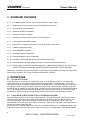
1
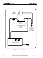
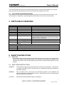
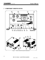
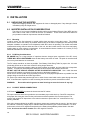
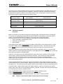
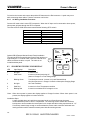
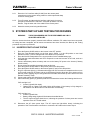
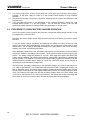
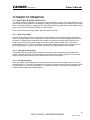
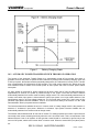
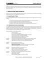
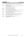
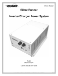
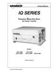
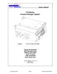
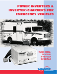
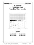
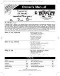
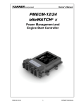
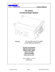
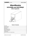
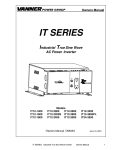
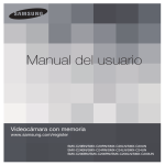
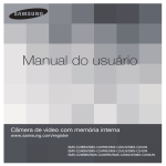
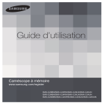
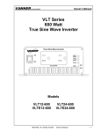
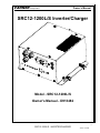
VANNER Incorporated Owner’s Manual SRC12-1200L/S Inverter/Charger Model - SRC12-1200L/S Owner's Manual - D913482 1 SRC12-1200L/S INVERTER/CHARGER 10/15/10 - 11:33 AM VANNER Incorporated Owner’s Manual OEM Alternator Fuse block within 18" of Battery 12 Volt Battery OEM Battery Common OEM ground at Starter or Engine Block Inverter/Charger Typical Inverter Installation 2 SRC12-1200L/S INVERTER/CHARGER 10/15/10 - 11:33 AM VANNER Incorporated 1 2 3 4 5 6 7 8 9 10 11 Owner’s Manual Table of Contents Introduction ................................................................................................................................. 4 Specifications .............................................................................................................................. 5 Standard Features....................................................................................................................... 6 Definitions.................................................................................................................................... 6 4.1 Quasi Sine Wave: .......................................................................................................................... 6 4.2 Load Demand Feature and Load Demand Mode: ......................................................................... 6 4.3 Automatic Transfer Switch: ........................................................................................................... 7 Parts and Accessories ................................................................................................................ 7 SAFETY INSTRUCTIONS ............................................................................................................ 7 6.1 READ ME ...................................................................................................................................... 7 6.2 SAVE THESE INSTRUCTIONS .................................................................................................... 7 6.3 General Precautions ...................................................................................................................... 8 6.4 Explosive Gas Precautions............................................................................................................ 8 6.5 Precautions When Working with Batteries .................................................................................... 8 Component Identification ......................................................................................................... 10 1 – ON/OFF/Reset Push Button............................................................................................................ 11 2 – INVERTER INDICATOR Light ........................................................................................................ 11 3 – BATTERY LOW INDICATOR Light................................................................................................. 11 4 – OVER TEMPERATURE INDICATOR Light .................................................................................... 11 5 – OVERLOAD INDICATOR Light....................................................................................................... 11 6 – BULK/ABSORPTION INDICATOR Light......................................................................................... 12 7 – FLOAT INDICATOR Light ............................................................................................................... 12 8 – REMOTE PANEL OR IFM1 JACK .................................................................................................. 12 9 – INVERTER CONTROL TERMINAL ................................................................................................ 12 10 – LOAD DEMAND ON/OFF (Switch 1) ............................................................................................ 12 11 – BATTERY TYPE Wet/Gel (Switch 2) ........................................................................................... 12 12 – CHARGING RATE High/Low (Switch 3) ...................................................................................... 12 13 – REMOTE CONTROL Selector IFM1/Remote (Switch 4) .............................................................. 12 14 – INVERTER CONTROL TERMINAL Enable/Disable (Switch 5) .................................................... 12 15 – 120V, 60Hz @ 15A Max. AC Output Utilizing the Phillips & Temro Connectors ........................... 13 16– 120V, 60Hz @ 15A Max. AC Output Utilizing GFCI convenience receptacle ................................ 13 17 – 15 Amp AC Output Circuit Breaker ............................................................................................... 13 18 – 15 Amp INV/CHG Circuit Breaker ................................................................................................. 13 19 – Mounting Flanges with 5/16” diameter mounting holes................................................................. 13 20 – M6 Cage Nut ................................................................................................................................. 13 21 – Air Exhaust Vents .......................................................................................................................... 13 22 – Air Intake Vents (rear and left side)............................................................................................... 13 23 – Chassis Ground Bonding Lug ....................................................................................................... 13 24 – 120V, 60Hz @ 15A Max. AC Input ................................................................................................ 13 25 – Negative DC input Connection (Black) .......................................................................................... 13 26 – Green DC interconnect Grounding wire ........................................................................................ 13 27 – Positive DC Input Connection (Red) ............................................................................................. 13 INSTALLATION .......................................................................................................................... 14 8.1 Unpacking the Inverter ................................................................................................................ 14 8.2 Inverter Installation Considerations ............................................................................................. 14 8.3 SR10 Remote Indicator Display .................................................................................................. 16 SYSTEM START-UP AND TESTING PROCEDURES .............................................................. 17 9.1 Inverter Start-up and Testing ....................................................................................................... 17 9.2 Procedure to Check Battery Charger Operation.......................................................................... 18 THEORY OF OPERATION ......................................................................................................... 19 10.1 Battery Charger Operation ........................................................................................................ 19 10.2 Automatic Power Transfer Switch Theory of Operation ............................................................ 20 PREVENTIVE MAINTENANCE .................................................................................................. 21 11.1 Maintenance Items .................................................................................................................... 21 3 SRC12-1200L/S INVERTER/CHARGER 10/15/10 - 11:33 AM VANNER Incorporated 12 Owner’s Manual 11.2 Troubleshooting Procedures ..................................................................................................... 21 APPENDICES ............................................................................................................................. 23 12.1 Problem Loads .......................................................................................................................... 23 12.2 Ampere-Hour (A-H): .................................................................................................................. 23 12.3 Discharge Rate: ......................................................................................................................... 23 12.4 Operating Temperature: ............................................................................................................ 23 12.5 Battery Age: ............................................................................................................................... 23 12.6 DC Power Consumption ............................................................................................................ 24 12.7 Inverter DC Input Current Requirements................................................................................... 24 1 INTRODUCTION Thank you for purchasing Vanner‟s SRC12-1200L/S Inverter/Charger. We are confident that you will be satisfied with its performance and its many features. With proper installation and care, you can look forward to years of service from this high performance product. This document will describe the operation, technical specifications, installation procedures, and accessories. If you require additional information, please contact Vanner at 1-800-AC Power (800-2276937) or 614-771-2718. WARNING: Before you install and use your inverter/charger be sure to read and save these safety instructions. PLEASE NOTE YOUR MODEL AND SERIAL NUMBER HERE FOR FUTURE REFERENCE Model Number _____________________________________________________________ Serial Number _____________________________________________________________ Date of Installation _____________________________________________________________ 4 SRC12-1200L/S INVERTER/CHARGER 10/15/10 - 11:33 AM VANNER Incorporated Owner’s Manual 2 SPECIFICATIONS Specifications Continuous Output Power Rating Output Surge Capacity DC Input Voltage DC Input Voltage Range AC Output Voltage AC Output Frequency AC Output Wave Form DC Input Amps Inverter OFF Inverter On, in Load Demand (asleep)* Inverter ON with No AC Load Inverter ON with AC Load Battery Charger Charging Output Capacity* Bulk Voltage* Float Voltage* AC Input Voltage AC Input Current for charging Transfer Switch AC Passthrough Model SRC12-1200L/S 1,200 Watts @ 25°C (77°F) Ambient 1,100 Watts @ 40°C (104°F) Ambient 2,600 Watts 13.6 VDC, Nominal 10.5 VDC min., 16.0 VDC max. 120 VAC RMS ± 10% 60 Hz ± 0.1% Modified Sine Wave 0.034 Amps Typical 0.075 Amps Typical 0.705 Amps Typical AC Output Load Watts ÷ 10 (approx.) 55 Amps (High) / 15 Amps (Low) 14.2 VDC (flooded), 14.1 VDC (gel) 13.2 VDC (flooded), 13.6 VDC (gel) 120 VAC 60Hz 14.0 Amps max 15 Amps Other Specifications AC Input 15 Amp AC Input Line Cord AC Output 15 Amp GFCI Receptacle Ambient Operating Temperature -40° to +104°F, -40° to + 40.0°C Cooling Thermostatically Controlled Fan Chassis Powder Coated Aluminum Dimensions 10.4”W x 6.0”H x 14.4”D Weight 25 lbs. * Determined by programming DIP switch setting Table 1 - Specifications 5 SRC12-1200L/S INVERTER/CHARGER 10/15/10 - 11:33 AM VANNER Incorporated Owner’s Manual 3 STANDARD FEATURES 3.1.1 True RMS regulated 120 volt ±10% AC 60 Hz Quasi-sine wave output 3.1.2 Output Short circuit / overload protection through electronic sensing 3.1.3 Input and Output circuit breakers 3.1.4 Automatic shutoff for Low Battery 3.1.5 Automatic shutoff for Overload 3.1.6 Automatic momentary shutoff/restart for Over temperature 3.1.7 Load Demand enable/disable switch 3.1.8 Built-in GFCI receptacle protected by a 15 amp AC output circuit breaker. 3.1.9 Capable of single wire control 3.1.10 Three Stage Battery Charger 3.1.11 Selectable high/low Charge Rate 3.1.12 Charging settings for gel or wet batteries 3.1.13 Automatic Transfer Switch with 5 second acceptance time delay 3.1.14 Thermostatically controlled cooling fan brings cooling air in through the back panel. 3.1.15 Indicator lights for ON/OFF/Load Demand status, Low Battery Warning/Shutoff, Over Temperature Shutoff, Overload Warning/Shutoff, and Bulk/Absorption Charge Stage, Float Charge Stage. Please note: The Battery Charger and Automatic Transfer Switch are operational only when AC input power (shore power) is present. The charger is ON when shore power is present. 4 DEFINITIONS 4.1 QUASI SINE WAVE: Quasi Sine Wave is also known as "modified sine wave" or "modified square wave." The inverter AC output wave shape is rectangular with the amplitude being proportional to battery voltage. The inverter varies the wave width as needed to maintain 120 volt true RMS output. A true RMS voltmeter is required to accurately measure the quasi sine wave inverter AC output voltage. Most AC loads, including computers, will operate with no problem on quasi sine wave. Inexpensive motors may have a more noticeable electrical "hum." An average responding volt meter will display AC voltages ranging from 95 to 135 volts, inversely proportional to battery voltage, and the AC voltage displayed will change as battery voltage changes. 4.2 LOAD DEMAND FEATURE AND LOAD DEMAND MODE: The Load Demand Feature is an energy conserving feature. This mode allows the inverter to go to sleep when the inverter is ON and the AC load has been less than 20 watts for approximately 5 seconds. The „Load Demand Mode‟ is often also described as „stand-by mode‟ or „sleep mode‟. While in the „Load Demand Mode‟ the inverter does not produce 120 volts AC. When an AC load greater than twenty watts is sensed, the inverter will turn fully ON. Some electronic or variable speed loads may not turn ON while the inverter is in Load Demand Mode. The load waits to see AC power and the inverter waits to see the load. For these loads, setting Selector Switch 6 SRC12-1200L/S INVERTER/CHARGER 10/15/10 - 11:33 AM VANNER Incorporated Owner’s Manual 1 to the OFF position can turn OFF the Load Demand Feature. This will cause the inverter to remain fully ON; producing 120 Volts AC whenever the inverter switch is ON regardless of AC load. 4.3 AUTOMATIC TRANSFER SWITCH: The Automatic Transfer Switch automatically allows input power from an external AC power source, such as shore power or a generator, to pass through the inverter output circuit for use by inverter loads. 5 PARTS AND ACCESSORIES Vanner Part Numbers Part Number Name SR10 Silent Runner Series Remote 011486 SR10 Remote Cable D011664 200 Amp Cube Fuse Kit 011756 200 Amp Cube Fuse 04522 200 Amp ANL Fuse 03637 ANL Fuse Holder IFM1 Interface Module D06638 D06639 D06781 Description Remote Display with On/Off Switch 10 foot Cable for SR10 Remote Cube Fuse, Nut and Mounting Bar Stud Bussmann FS-HVBF-200 Cube Fuse Bussmann ANL-200 fuse Fuse holder for ANN and ANL fuses Interface to allow remote control of inverter via customer supplied ON/OFF switch(s), and to accept remote display panels for inverter and charger. Inverter Display Panel (Requires IFM1) Charger Display Panel (Requires IFM1) ON/OFF Rocker Switch w/ 8' cable (Requires IFM1) Remote Inverter Panel Remote Charger Panel Remote ON/OFF Rocker Switch International Truck and Engine Corporation® part numbers Part Number Description 3664124C91 Positive Battery Cable harness 3664125C91 Negative Battery Cable harness 3664126C91 Ground Cable 6 SAFETY INSTRUCTIONS 6.1 READ ME This manual contains important safety and operating instructions for the Vanner Incorporated Silent Runner Series Power Inverter/Charger System. The SR-Series Inverter/Charger is designed to be compliant with UL458, Power Converters/Inverters and Power Converter/Inverter Systems for Land Vehicles. 6.2 SAVE THESE INSTRUCTIONS WARNING This equipment employs components that tend to produce arcs and sparks. To prevent fire or explosion, DO NOT install in confined areas or compartments that contain batteries or flammable materials. WARNING Risk of electrical shock. Use only the circuit breaker(s) specified in the installation and operating instructions supplied with this inverter. Other types may fail to operate properly when connected to this equipment. CAUTION Read Owners Manual BEFORE wiring or powering up. 7 SRC12-1200L/S INVERTER/CHARGER 10/15/10 - 11:33 AM VANNER Incorporated Owner’s Manual CAUTION DO NOT cover or obstruct ventilation openings. DO NOT mount in zero-clearance compartments. Overheating may result which may diminish system capacity. NOTICE The output of this device in not sinusoidal. The SR-SERIES inverter has a total harmonic distortion of 34.6 percent and maximum single harmonic of 24 percent. 6.3 GENERAL PRECAUTIONS 1 2 3 4 5 6 7 8 9 10 6.4 Do not expose the SR-Series Inverter to direct water spray or snow. To reduce the risk of a fire hazard, do not cover or obstruct the ventilation openings. Do not install this unit in a zero-clearance compartment. The result may be overheating or diminished performance. To avoid the risk of fire, electric shock, or injury to persons, do not use attachments, breakers, fuses, etc. not recommended or sold by Vanner Incorporated. Vanner recommends that all DC and AC electrical wiring be performed by a certified electrician or technician to ensure compliance with all proper national and local wiring regulations. To avoid a risk of fire and/or electric shock, always verify wiring connections are in good electrical condition. All external conductors must use proper wire size to avoid dangerous overheating or diminished performance. If the Vanner inverter system has been dropped or damaged in any way, do not operate until its operation has been verified to be safe by a qualified technician. To reduce the risks of electric shock always disconnect the AC and DC connections to the Vanner Inverter system before attempting any maintenance. Simply turning the unit off does not prevent electric shock. The SR-Series inverter system must be properly grounded in accordance with local and national codes and ordinances before operation. For most installations the negative (ground) conductor should be bonded to the grounding system at one and only one point in the system. Do not disassemble the SR-Series Inverter/Charger. See the service section of this manual for instructions on obtaining service for your Inverter/Charger. Attempting to service the unit yourself may result in a risk of electrical shock or fire. EXPLOSIVE GAS PRECAUTIONS This equipment contains components, which tend to produce arcs or sparks. To prevent fire or explosions do not install in compartments containing batteries or flammable materials or in locations that require ignition-protected equipment. This includes any space containing gasoline-powered machinery, fuel tanks, or joints, fittings, or other connection between components of the fuel system. Working in the vicinity of a lead-acid battery is dangerous. Batteries generate explosive gases during normal battery operation. To reduce the risk of battery explosion, follow these instructions and those published by the battery manufacturer and the manufacturer of the equipment in which the battery is installed. 6.5 1 2 3 4 8 PRECAUTIONS WHEN WORKING WITH BATTERIES Always have someone within range of your voice to come to your aid when you work near a lead-acid battery. Have access to plenty of fresh water and soap nearby in case battery acid contacts skin, clothing, or eyes. Always wear complete eye protection and clothing protection. Avoid touching eyes while working near batteries. If battery acid contacts skin or clothing, wash immediately with soap and water. If acid enters eye, immediately flood eye with running cold water for at least 20 minutes and get medical attention immediately. SRC12-1200L/S INVERTER/CHARGER 10/15/10 - 11:33 AM VANNER Incorporated 5 6 7 Owner’s Manual NEVER smoke or allow a spark of flame in the vicinity of batteries. Gases produced by batteries are explosive. Care should be taken when working with metal tools around batteries. Potentials for spark exists or short-circuit of the battery or other electrical part that may cause an explosion. Never charge a frozen battery. Battery temperature needs to be above 32°F (0°C) before charging. 9 SRC12-1200L/S INVERTER/CHARGER 10/15/10 - 11:33 AM VANNER Incorporated Owner’s Manual 7 COMPONENT IDENTIFICATION 15 16 17 18 AC OUTPUT IN C O R P O R A TE D INV/CHG MATING ATTACHMENT PLUG/CABLE AVAILABLE FROM PHILLIPS & TEMRO AC OUTPUT P/N: 8500641 120 VAC 60Hz FOR DISCONNECT USE ONLY - NOT FOR CURRENT INTERRUPTION 1 2 0 0 W a tt In v e r te r INVERTER CONTROL TERMINAL IFM1/REMOTE REMOTE OR IFM1 ON OFF/RESET INVERTER BATTERY LOW OVER TEMP OVER LOAD BULK/ ABSORPTION CHARGE RATE INVERTER CONTROL TERMINAL BATTERY TYPE LOAD DEMAND FLOAT 1 12345 STEADY=INVERTER ON 2 3 4 5 OFF FLOODED 55A REMOTE ON ON GEL 15A IFM1 OFF CHARGER BLINK=STANDBY/LOAD DEMAND 1 2 3 4 5 6 7 8 9 25 21 10 11 12 13 14 26 27 24 21 20 19 Figure 2 10 23 22 SRC12-1200L/S Component Identification SRC12-1200L/S INVERTER/CHARGER 10/15/10 - 11:33 AM VANNER Incorporated Owner’s Manual 1 – ON/OFF/RESET PUSH BUTTON The ON/OFF Switch is a pushbutton switch used to turn the inverter function ON/OFF and is used as a RESET Switch. (Note: The charger function is controlled ON/OFF by the presence/absence of shore power.) When an automatic shutdown has occurred due to a fault, one of the fault indicator lights will be displayed until the inverter is RESET. Reset the inverter by turning the ON/OFF Switch OFF or by turning a remote switch OFF. Inverter Indicator Lights 2 – INVERTER INDICATOR LIGHT Light Display Description No light Inverter is OFF. Solid Green Inverter is ON and is producing AC power. Blinking Green Two blinks per second. Inverter is in Load Demand Mode. Blinking Green One blink per second. Inverter switch is ON. Shore power is present. 3 – BATTERY LOW INDICATOR LIGHT Light Display Description Red Light is ON The inverter is ON but battery voltage has decreased less than 11 volts DC. Automatic inverter shutdown for low battery at 10.5 volts is imminent unless the battery voltage is increased. Blinking Red Light The inverter has shut itself OFF due to a low battery voltage caused by voltage to the inverter dropping below 10.5 volts. The Inverter ON/OFF Switch must be cycled to reset and restart the inverter. 4 – OVER TEMPERATURE INDICATOR LIGHT Light Display Description Red Light is ON The inverter has shut itself OFF due to excessive heating or load. Check for blocked vents or any type of air obstruction to the inverter and/or remove load. The Inverter will automatically restart when the inverter cools down. 5 – OVERLOAD INDICATOR LIGHT Light Display Description Blinking Red The inverter has shut itself OFF due to overload. The Inverter ON/OFF Switch must be cycled to reset and restart the inverter. 11 SRC12-1200L/S INVERTER/CHARGER 10/15/10 - 11:33 AM VANNER Incorporated Owner’s Manual Charger Indicator Lights 6 – BULK/ABSORPTION INDICATOR LIGHT (See „Battery Charger Theory of Operation‟ for battery charging performance details.) Light Action Description Blinking Yellow The unit is in Charger Mode (shore power is present) and the charger is in either the BULK STAGE or ABSORPTION STAGE of the battery charging cycle. 7 – FLOAT INDICATOR LIGHT (See „Battery Charger Theory of Operation‟ for charger performance details.) Light Action Description Solid Green The unit is in Charger Mode (shore power is present) and the charger is in the FLOAT STAGE of the battery charging cycle. Remote Control Terminals 8 – REMOTE PANEL OR IFM1 JACK Eight-wire modular jack for use with optional SR10 Remote or IFM1. (The six-conductor IFM1 cable will work in this jack.) 9 – INVERTER CONTROL TERMINAL A 1/4" spade connector for use with an external 12v source for inverter remote control. Configuration switches 4 and 5 must be UP to activate this feature. The inverter will turn ON when a continuous 12 volt signal is applied, and turn OFF when the 12 volt signal goes away. The SR10 Remote Control Panel is required to initially turn the inverter ON after connection to battery voltage. Configuration Switches 10 – LOAD DEMAND ON/OFF (SWITCH 1) Turn Load Demand Function ON/OFF. See definition of Load Demand in Section 1.3. With Load Demand ON the inverter operates only when a load greater than 20 Watts is applied. Some electronic or variable speed loads may not turn ON while the inverter is in Load Demand. 11 – BATTERY TYPE WET/GEL (SWITCH 2) Select wet or gel battery-charging voltages. 12 – CHARGING RATE HIGH/LOW (SWITCH 3) Select 55 amp charge rate in High or 15 amp charge rate in Low. 13 – REMOTE CONTROL SELECTOR IFM1/REMOTE (SWITCH 4) Set to Remote for use with SR10 Remote. Set to IFM1 for use with IFM1 or no remote. 14 – INVERTER CONTROL TERMINAL ENABLE/DISABLE (SWITCH 5) Activates function of Inverter Control Terminal when Switch 4 is in Remote. When enabled, a continuous 12v signal is REQUIRED to turn the inverter function ON. SR10 Remote is REQUIRED to initially turn the inverter ON after connection to battery voltage. 12 SRC12-1200L/S INVERTER/CHARGER 10/15/10 - 11:33 AM VANNER Incorporated Owner’s Manual Additional Features 15 – 120V, 60HZ @ 15A MAX. AC OUTPUT UTILIZING THE PHILLIPS & TEMRO CONNECTORS All output will be protected for ground faults by means of the Ground Fault Circuit Interrupter (GFCI) 16– 120V, 60HZ @ 15A MAX. AC OUTPUT UTILIZING GFCI CONVENIENCE RECEPTACLE 17 – 15 AMP AC OUTPUT CIRCUIT BREAKER Output CIRCUIT BREAKER (top breaker) protects AC Output at the receptacles. 18 – 15 AMP INV/CHG CIRCUIT BREAKER Input CIRCUIT BREAKER (bottom breaker) protects the input cord. 19 – MOUNTING FLANGES WITH 5/16” DIAMETER MOUNTING HOLES 20 – M6 CAGE NUT 21 – AIR EXHAUST VENTS Keep two inches clearance around vent area 22 – AIR INTAKE VENTS (REAR AND LEFT SIDE) Keep two inches clearance around vent area 23 – CHASSIS GROUND BONDING LUG Use 8 AWG or larger copper conductor to connect chassis bonding lug to the vehicle chassis. 24 – 120V, 60HZ @ 15A MAX. AC INPUT 25 – NEGATIVE DC INPUT CONNECTION (BLACK) BE AWARE that, as a large number of capacitors become charged upon completion of the DC circuit, THERE WILL BE A LARGE SPARK when the last battery connection is made. The spark is normal and will occur every time batteries are connected. 26 – GREEN DC INTERCONNECT GROUNDING WIRE Grounding wire for the DC interconnects. This cable should be securly bonded to the chassis of the vehicle. 27 – POSITIVE DC INPUT CONNECTION (RED) BE AWARE that, as a large number of capacitors become charged upon completion of the DC circuit, THERE WILL BE A LARGE SPARK when the last battery connection is made. The spark is normal and will occur every time batteries are connected. 13 SRC12-1200L/S INVERTER/CHARGER 10/15/10 - 11:33 AM VANNER Incorporated Owner’s Manual 8 INSTALLATION 8.1 UNPACKING THE INVERTER Inspect the shipping container and equipment for loose or damaged parts. If any damage is found, immediately notify the freight carrier. 8.2 INVERTER INSTALLATION CONSIDERATIONS The wiring of your inverter installation should conform to the National Electric Code (NEC) and any other state or local codes in effect at the time of installation. These codes have been written for your protection and their requirements should be followed. 8.2.1 Mounting Locate a secure, dry, flat horizontal or vertical surface large enough to mount the inverter. The location should be as close to the battery as possible without being in the same compartment and should provide adequate ventilation to maintain room temperature while the inverter is operating. The location must allow unobstructed cooling airflow at sides and rear of the unit, and the location must be free from road spray, dripping water or other moisture contamination. A recommended minimum clearance of 2 inches (51 mm) should be maintained on all sides of the unit. 8.2.2 DC Wiring Considerations BE AWARE that, as a large number of capacitors become charged upon completion of the DC circuit, THERE WILL BE A LARGE SPARK when the last battery connection is made. The spark is normal and will occur every time batteries are connected. The DC cables should be as short as possible. See Battery Cable Sizing Table for proper size. It is more electrically efficient to run the lower current AC wiring longer distances. Route the DC positive and negative cables as close together as possible, and use cable ties to keep them together. This reduces electromagnetic radiation that could interfere with sensitive electronics. DO NOT USE THE VEHICLE CHASSIS AS THE DC NEGATIVE CONDUCTOR. Use a cable the same size as the DC positive to go directly from the inverter to the battery negative (-). Route the AC and DC power wiring separately and with as much physical separation as possible from low voltage wiring such as audio and video signal wires. DC power input cables that pass through steel or other ferrous metal walls need to pass through the same hole. If two holes are required cut a slot connecting the two holes to prevent a transformer effect. WARNING: 8.2.3 Do not allow wire fragments or metal shavings to enter the inverter in any way. DC INPUT WIRING CONNECTIONS A DC fuse is REQUIRED to protect the inverter and the DC cables. DC input connectors have been provided to accommodate proper cable hook-up. Good DC connections and proper wire sizing are critical for the performance and safe operation of the inverter system. The positive and negative DC inputs have color-coded connectors to protect the “live” connection from any shorting materials. Wire sizing charts published in the NEC may allow a greater amp capacity than we require. We have sized the cable for a minimum voltage drop to maintain better performance of your inverter installation. For best performance, wire the DC negative directly back to the battery through Battery cables listed in the table below; do not use the vehicle chassis as the DC negative conductor. 14 SRC12-1200L/S INVERTER/CHARGER 10/15/10 - 11:33 AM VANNER Incorporated Owner’s Manual The wiring of your inverter installation should conform to the National Electric Code (NEC) and any other state or local codes in effect at the time of installation. Article 551 of the NEC requires the overcurrent protective device shall be installed in an accessible location on the vehicle within 18 in. (457 mm) of the point where the power supply connects to the vehicle circuits. Bussmann Fuse Vanner part number Fuse Holder Vanner part number ANN200 FS-HVBF-200 Cube Fuse or Vanner #04522 Vanner #011756 Bussmann 4164 (Required with ANN Style fuse) Vanner #03637 Positive Battery Cable ITEC # 3664124C91 Negative Battery Cable ITEC # 3664125C91 Ground Cable ITEC # 3664126C91 Table 2- DC Wiring and Fuse Size Chart 8.2.4 DC Wiring Installation Procedure Make sure all power to the vehicle wiring harness is disconnected. Verify that the inverter is turned OFF. This can be accomplished by checking that the ON-OFF/RESET Inverter Switch is in the OFF-RESET position, (The button should NOT be pushed in.) and no lights are lit on the status lights. Select a location for the unit. An ideal installation location has the following characteristics: Close to the battery (usually within six feet). Protected from the weather. Well ventilated. Verify battery positive cable is disconnected from battery. Install cables in the following manner: Connect the negative battery cable harness to the negative DC input blue connector. Twist the connector until it locks. Do not connect the positive battery cable to the positive DC input red connector at this time. Route the negative and positive battery cables from the inverter to the battery but do not connect to the battery at this time. Protect cables with grommets or other appropriate means where they may contact hard, sharp edges throughout the installation path. Install fuse in the positive DC input cable between the battery and inverter. Installed a Fuse (see table above) within 18 inches of the battery or DC wiring bus system. This is required to comply with safety agency installation requirements. Be sure to mount the fuse in an easily accessible location for replacement. It is also “good practice” to note on the inverter to check the fuse condition before involving any troubleshooting procedure. Connect ground Bonding Lug. (Component Item 23). Use 8 AWG or larger copper conductor to connect chassis bonding lug to the vehicle chassis. Additional grounding is required using the ground cable listed in the table above. This cable will snap-lock together with the inverters black connector (Component Item 26). Connect the black, negative battery cable to the battery negative (-) terminal. Connect the red, positive battery cable to the in/line fuse near the battery positive (+) terminal. The other side of that fuse should then be connected to the Positive (+) battery terminal. Verify the black battery cable is tightly connected to the negative (-) battery terminal. Verify the red cable harness is tightly connected to one side of the fuse. Verify the “Other side” of the fuse is tightly connected to the positive (+) battery terminal. Note: Failure to connect these cables correctly may void your warranty. 15 SRC12-1200L/S INVERTER/CHARGER 10/15/10 - 11:33 AM VANNER Incorporated Owner’s Manual Go back to the inverter and connect the positive DC harness to the Red connector. A spark may occur while connecting these cables. Twist the connector until it locks. 8.2.5 AC Wiring Installation Procedure Connect AC loads to the inverter GFCI receptacle. When the AC input cord is connected to shore power, shore power will pass through the GFCI receptacle. The Vanner SR12-1200L/S has been tested with the following GFCI outlet‟s: Manufacturer Model Hubbell GFR5252W Hubbell GFR5252WA Hubbell GFR5252I Hubbell GFR5252WL Leviton 6599-I Leviton 1591 Table 3 – Authorized acceptable GFCI’s AC POWER CONTROL Optional SR10 Remote Monitor/Control Panel Installation The optional SR10 Remote Monitor/Control Panel requires an eight-conductor 1:1 modular cable, Vanner 011486 ten-foot cables, an Ethernet cable, or equal. The cable is not included with the panel. 8.3 Power On 1 SR10 REMOTE INDICATOR DISPLAY Standby/ Bulk Charge System ON Fault 2 System OFF LED Light Display* Description 1 No Light Inverter is OFF 1 Solid Green Inverter is ON and producing AC power or Charger is in Float Charge Stage 1 Blinking Green Two blinks per second - Inverter is in Load Demand Mode One blink per second - Charger is in Bulk or Absorption Charging Stage 2 No Light No Fault Conditions 2 Solid Red Inverter is in Over Temperature condition 2 Blinking Red Inverter is overloaded or DC voltage is to low *Note: When shore power is present the display applies to Charger functions. When shore power is not present, the display applies to inverter functions. Installation Steps Locate a suitable place to install the remote panel such as a flat surface near the power control/distribution panel or driver‟s compartment. The mounting surface should have sufficient back space to accommodate the remote panel's min. depth and cable routing requirements of 1 ½”. Cut surface material large enough to accommodate the remote cable connector and board area leaving sufficient surface material to attach panel with #8 mounting screws. 16 SRC12-1200L/S INVERTER/CHARGER 10/15/10 - 11:33 AM VANNER Incorporated 8.3.1 Route the 10-ft. interface cable (011486) from the remote panel mounting area to the inverter being careful to avoid unprotected sharp corners or moving parts. 8.3.2 Turn off inverter, and then plug the interface cable into the inverter's front panel “Remote/IFM1” connector. Verify that dip Switch 4 is set to Remote. Plug the other end of the cable into the remote panel. 8.3.3 Mount the remote panel using two #8 screws. Owner’s Manual 9 SYSTEM START-UP AND TESTING PROCEDURES WARNING: THESE PROCEDURES ARE TO BE PERFORMED ONLY BY A QUALIFIED INSTALLER. After the inverter has been properly mounted with sufficient ventilation, DC cables have been connected, AC wiring has been completed, and all remote connections have been checked, the Start-up and Testing procedure may now be performed. 9.1 1. 2. 3. 4. 5. 6. 7. 8. 9. 10. 11. INVERTER START-UP AND TESTING Place the System On/Off switch on the inverter in the OFF position. Place the Load Demand switch on the front panel, Switch 1, to the ON position to test Load Demand function. It can be changed later if this feature is not preferred. Place the Wet/Gel Setup switch to the correct position for the installed battery type. Verify that the external breakers and GFCI receptacle is reset and connect an AC load, such as a 100-Watt light. Connect both battery cables to battery and turn on the battery DC power to the inverter (if battery switch is used). Do not connect shore/utility (generator) power at this time. Place the System On/Off switch on the Inverter panel to the ON position. Place the System On/Off switch on the Remote panel (if used) to the ON position. Plug AC output test light (e.g. 100 watt trouble light) into 15A convenience receptacle and turn on to verify inverter produces AC power and the Load Demand function allows the unit to power up from stand-by mode. Applying any AC load greater than 20 Watts should wake up the inverter from Load Demand “stand by” mode. Connect and activate AC shore/power (or generator). When shore/utility power (or generator) has been connected the inverter the following should occur: If AC test light is off. Inverter Light will blink slowly Charge Bulk or Charge Float mode Lights will illuminate. (If the battery is fully charged, it will advance from Bulk mode to Float mode after a time delay). If AC test light is on. Inverter Light will blink. Battery charge stage Lights will illuminate as described above. The AC output test light should be on, indicating the presence of shore power and correct operation of the AC Transfer switch. 12. Disconnect the AC shore power input. The AC output test light blinks shortly, indicating the operation of the Transfer switch connection to connect the AC loads to the inverter output. 17 SRC12-1200L/S INVERTER/CHARGER 10/15/10 - 11:33 AM VANNER Incorporated 13. 14. 15. 9.2 Owner’s Manual The Inverter Light on the inverter control panel has a solid green light indicating correct inverter operation. At this point, apply AC loads up to the inverter's rated capacity to verify full-power operation. Disconnect all AC loads. The Inverter Light blinks, indicating that the inverter has returned to Load Demand mode. If the Load Demand function is not appropriate for the intended application, change the Load Demand Switch, Switch 1, to the OFF position. This will allow the inverter to be fully ON continuously unless switched off with the On/Off front panel switch or remote control. PROCEDURE TO CHECK BATTERY CHARGER OPERATION Due to the amount of time to perform this procedure, verifying the battery charger function, it may be postponed to a convenient time. Determine the correct charger output amps and place the front panel switch (3) position to match this value. To test the battery charger operations, first discharge the battery by placing a large AC load (approx. 50% of the unit‟s rated capacity) on the system and operating the inverter with AC input disconnected. The AC load will discharge the battery over a time relative to the amount of battery capacity, size of load, and ambient temperature. When the battery charge level is low, the Battery Low Light turns on and will stay on until the battery voltage has dropped to the Battery Low shutdown. The inverter then shuts off and the Light begins to blink. The battery voltage has decayed to 10.5 Vdc. Now, apply shore power and observe the battery charger operation. The system begins with the Charger-Bulk Light blinking, indicating bulk charge operation. This supplies a constant current charge output. Connect an ammeter to the DC cables between the inverter and the battery to monitor the current (DC amps), and a voltmeter to the battery to monitor the battery voltage rising. After some time, the battery voltage rises to the Absorption voltage (14.4 VDC for wet batteries or 14.1 VDC for gel batteries). The Charger-Bulk light continues to flash, indicating the charger is in Bulk or Absorption mode. The battery voltage remains constant (Absorption voltage value), and the charger output current tapers off. After approximately twenty minutes, the charge advances to Float mode. The Charger Float Light turns ON and the battery voltage drops to the float voltage value (13.2 VDC for wet batteries or 13.6 VDC for gel batteries). The charger will remain in this stage until shore power is removed or until the battery will again accept the bulk charge amperage. 18 SRC12-1200L/S INVERTER/CHARGER 10/15/10 - 11:33 AM VANNER Incorporated Owner’s Manual 10 THEORY OF OPERATION 10.1 BATTERY CHARGER OPERATION The SRC12-1200L/S incorporates an automatic, three-stage battery charger. This design enables the unit to automatically charge batteries, maintaining the battery's integrity and reducing the likelihood of premature failure. The battery charger is designed to be used with lead-acid type batteries including sealed and gel types, but not for nickel-cadmium (Ni-Cad) or nickel-iron types. There are three automatic charge stages; Bulk, Absorption, and Float. 10.1.1 Bulk Charge Stage The Bulk Charge Stage (fixed current) provides a fixed charging current for rapid charging of the battery bank. The charger output current is adjustable, 15-Amp or 55-Amp, to match the charging requirements of the battery. The Bulk Stage is initiated when the battery will accept the charging amps selected. As the battery accepts charge, the battery voltage will rise to the charger's Bulk Voltage value, 14.4 VDC for flooded batteries, or 14.1 VDC for gel batteries. When battery voltage reaches the Bulk Voltage Value the Bulk Charging Stage is complete. At this point, the battery is approximately 80-percent charged. 10.1.2 Absorption Charge Stage During Absorption Charge Stage (fixed voltage), the charger's output voltage remains fixed at the Bulk Charge value and the output current will decrease as the battery becomes fully charged. The Absorption Stage ends after twenty minutes and the charger advances to the Float Stage. 10.1.3 Float Charge Stage When the charger enters Float Stage, its output voltage is reduced to the float voltage value 13.2 VDC for flooded batteries, or 13.6 VDC for gel batteries. This setting is sufficient to keep the battery charged, but not so high as to boil or over-charge the batteries. The charger will remain in Float Stage until the battery will accept the Bulk Charge Output Amps selected. 19 SRC12-1200L/S INVERTER/CHARGER 10/15/10 - 11:33 AM VANNER Incorporated Figure 1 Owner’s Manual Battery Charging Graph 10.2 AUTOMATIC POWER TRANSFER SWITCH THEORY OF OPERATION The function of the Automatic Transfer Switch is to automatically accept AC input power from shore or generator, and use this power to operate inverter loads and to provide power for battery charging. Upon loss of AC input power, the transfer switch automatically switches the AC loads back to inverter power. Transfer time is approximately 30 milliseconds (0.030 seconds). The 0.030 second transfer time allows all but the most sensitive loads to transfer from inverter power to shore power and back to inverter power without interruption. AC input voltage is monitored for proper tolerance at all times. When the AC input is within tolerance for approximately 5 seconds, the power is passed through to the output circuit and the SRC12-1200L/S automatically switches from inverter mode to battery charger mode. The unit automatically switches back to inverter mode when input power is disconnected or when input power is no longer within tolerance. See specifications page for AC input voltage tolerances. The 5 second delay occurs only if the inverter is fully ON when input power becomes available. There is no 5 second time delay if the inverter is in the „Load Demand Mode‟ when input power becomes available. The factor that determines whether the unit is in „inverter mode‟ or „battery charger mode‟ is the presence or absence of „in-tolerance‟ input power. Whenever „in-tolerance‟ input power becomes available the unit automatically switches from inverter mode to charger mode. The transfer switch switches both AC hot and AC neutral. For safety purposes the inverter output neutral is connected to the inverter chassis ground only when the unit is in inverter mode. This is a requirement of the National Electric Code for all systems of this type that neutral should be connected to ground only at the source of AC power, which is the inverter when in inverter mode. When an external AC input (shore power, 20 SRC12-1200L/S INVERTER/CHARGER 10/15/10 - 11:33 AM VANNER Incorporated Owner’s Manual generator) is available, the SRC12-1200L/S transfer switch system breaks the connection between neutral and inverter chassis ground. The neutral-to-ground connection for passthrough power is then provided by the AC input source. 11 PREVENTIVE MAINTENANCE There are no user serviceable components inside the inverter. For service refer to the Vanner Incorporated Service Department or other qualified service personnel. 11.1 MAINTENANCE ITEMS For continued reliability and safety, a monthly maintenance program should be implemented to include the following: 1. 2. 3. 4. Check to insure that all DC and AC wiring connections are secured and corrosion free. Check air ventilation openings for dust and other obstructions Examine receptacle, indicators and switches for cracks and breaks. Examine for any surfaces that are discolored or deformed due to excessive heat. 11.2 TROUBLESHOOTING PROCEDURES The following are the most common questions heard by Vanner service professionals. If your situation does not apply to the following categories, please contact your local Vanner Incorporated Service Center or the Vanner Incorporated Customer Service department: 1-800-AC-POWER (1-800-227-6937). Please have your model and serial number available when consulting customer service. ALWAYS CHECK THE FOLLOWING FIRST: DC Fuse condition AC output and input breakers Check all GFCI breakers as equipped throughout AC system Unit On/Off and Remote On/Off switch positions Check battery connections for tightness or corrosion Check battery voltage at battery and inverter Symptom Solution ON Light does not light steadily after pushing in the ON/OFF/RESET Switch. Light flashes two blinks per second in Load Demand Stand-by mode. Light flashes one blink per second when utility power is present. Symptom Solution Inverter Light does not illuminate Reset On/Off Switch on unit and remote Disconnect remote switch and attempt starting with unit On/Off switch Check DC fuse condition Verify battery voltage is above 10.5 volts at inverter Symptom Solution ON light fully illuminates. AC load does not run. Check and reset AC circuit breakers. Check and reset any GFCI breakers in AC circuit. Verify AC load and wiring is in proper condition. Symptom Solution BATTERY LOW light illuminates when AC loads is applied. Check battery connections. Check battery condition. Recharge battery if voltage is less than 10.5 VDC. 21 SRC12-1200L/S INVERTER/CHARGER 10/15/10 - 11:33 AM VANNER Incorporated Owner’s Manual Check the charging system for proper operation (vehicle alternator, generator). Symptom Solution OVERTEMP light illuminates. Something has caused the unit to overheat. Check for obstruction of airflow to the cooling fan or from ventilation holes. Verify AC load is within unit's rated capacity. Symptom Solution OVERLOAD light illuminates with AC load applied. Verify AC load is within unit's rated capacity. Symptom Solution DC fuse blows when connecting DC input cables. Check for reverse polarity: red cable to battery positive (+), black cable to battery negative (-) The unit may be damaged and require repair service. Symptom Solution Excessive audible buzzing during inverter operation but inverter operates loads. Check mounting bracket bolt tightness Remount inverter with rubber insulator washers Symptom Solution AC loads does not seem to be fully energized when operating from inverter power. Check AC output voltage at convenience receptacle with a “True RMS” meter. Check for overheated DC or AC wiring Symptom Solution Unit does not operate and a “burnt wire” smell emits from inverter. Disconnect AC loads and battery immediately Unit may require service 22 SRC12-1200L/S INVERTER/CHARGER 10/15/10 - 11:33 AM VANNER Incorporated Owner’s Manual 12 APPENDICES 12.1 PROBLEM LOADS Although modified sine wave inverters will operate most AC loads, some loads may exhibit problems because the waveform is different than the pure sine wave of utility power. This is due to the square wave components and that the peak voltage is not quite as high as a pure sine wave. Loads that may exhibit problems include: motor speed controls (found on ceiling fans and air conditioner fans), light dimmer controls, clocks, microwave ovens (cooking time may vary and the clock may be erratic), video monitors and TVs (may have lines in the picture), AM radios (may pick up noise), laser printers, copying machines, fluorescent lights, and power supplies in some electronic devices. Rechargeable battery devices may also overheat and be damaged by the inverter. If you desire to operate a rechargeable battery device on the inverter you should first power it up and closely observe it for a period of time to ensure that it does not run too hot. 12.2 AMPERE-HOUR (A-H): A unit of measure for a battery's electrical storage capacity, obtained by multiplying the discharge current in amperes by the time in hours of discharge. The rating is usually for a discharge period of 20 hours and an end voltage of 10.5 volts. Example: A battery, which delivers 5 amperes for 20 hours, has a capacity of 100 A-H. 5 amperes x 20 hours = 100 Amp-Hr.) The reason the A-H rating is misunderstood is simple. A battery that has a rating of 100 AH cannot always deliver 100 A-H. The underlying reason is the efficiency with which the battery converts its chemical energy into electric energy. The A-H capacity of a battery is affected in the following ways: 12.3 DISCHARGE RATE: A battery becomes less efficient as the discharge current increases. For example, a typical 100 A-H battery is specified to be able to deliver 5 amps for a period of 20 hours. If the discharge current were increased to 25 amps, the capacity will be reduced to approximately 75 A-H (25 amps x 3 hours = 75 A-H). 12.4 OPERATING TEMPERATURE: A battery becomes less efficient at lower temperatures. Most battery manufacturers specify the battery A-H capacity at 80°F (27°C). At a temperature of 32°F (0°C), the same battery will have only about 65% of its rated capacity even though it may be fully charged. At a temperature of 0°F (-18°C), a battery's capacity will be reduced to about 40% of its rated capacity. 12.5 BATTERY AGE: As a battery is used, some of the active material on the battery plates will deteriorate and become useless. As the battery gets older, there will be less and less useful material left on the plates and the operating time will become noticeably shorter. A battery will age faster (loose active material from its plates faster) if it is deeply discharged regularly, if it is left in a discharged state for extended periods of time, or if it is repeatedly overcharged. 23 SRC12-1200L/S INVERTER/CHARGER 10/15/10 - 11:33 AM VANNER Incorporated Owner’s Manual 12.6 DC POWER CONSUMPTION An inverter takes in DC power, and produces AC power to operate attached loads. In general, we can see a direct relationship between DC input power and AC output power. This allows us to establish the following rule: For every 10 watts of AC output power, an inverter requires one amp of DC input power on a 12 volt input inverter. Example: An inverter powering a 1,000-watt AC load requires 100 amps DC. 1000 watts/10 = 100 amps Using our rule, we can determine the requirements for an electrical system needed to power our inverter (typically, an alternator and battery combination, or a photovoltaic panel and battery combination). 12.7 INVERTER DC INPUT CURRENT REQUIREMENTS A DC to AC inverter converts DC power into AC power. For the purposes of this discussion, power (watts) is equal to the supply voltage (volts) multiplied by the current draw (amps) from the supply for both AC and DC circuits. For example, 2,400 watts = 12 volts DC x 200 amps, and 2,400 watts = 120 volts AC x 20 amps. From these two examples of 2,400 watts at 12 volts and 2,400 watts at 120 volts, it is easy to see that since there is a 1 to 10 voltage conversion (12 to 120), there is a 10 to 1 amp conversion (200 to 20). A more accurate relationship between the input power and output power is: (DC Input Power) x (Efficiency) = (AC Output Power) This formal relationship has lead to the following rule of thumb for estimating the DC input amps for an inverter: For 12 volt DC inverters: output watts ÷ 10 = DC input current This rule of thumb can be used to estimate the minimum alternator size required for your application and is also used later in calculating the minimum size battery required when operating from battery only. The following examples should help to clarify the use of this rule of thumb. Example A: What is the DC current draw of a 12 volt DC input inverter when it is operating a vacuum cleaner with a nameplate rating of six amps at 120 volts AC? The appliance rating is given in amperes, so we must first calculate the power it consumes. Then the rule of thumb can be used to find the DC input current of the inverter. Output power = 120 volts x 6 amps = 720 watts, and DC input current = 720 ÷ 10 = 72 amps DC. This information on estimating the DC input current requirement for an inverter would allow you to size an alternator or charging system to supply an inverter for continuous operation. 24 SRC12-1200L/S INVERTER/CHARGER 10/15/10 - 11:33 AM VANNER Incorporated Owner’s Manual Vanner Incorporated 4282 Reynolds Drive Hilliard, Ohio 43026 1-800-AC POWER (1-800-227-6937) Tel: 614-771-2718 Fax: 614-771-4904 www.vanner.com e-mail: [email protected] Manual Part Number D913482-B Printed in USA 25 SRC12-1200L/S INVERTER/CHARGER 10/15/10 - 11:33 AM