1
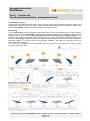
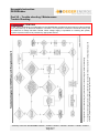
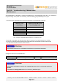
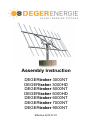
Assembly Instruction
DEGERtraker 3000NT
DEGERtraker 3000HD
DEGERtraker 5000NT
DEGERtraker 5000HD
DEGERtraker 6000NT
DEGERtraker 7000NT
DEGERtraker 9000NT
Effective 2012-07-01
Assembly Instruction
DEGERtraker
List of content
Part I
Basics
Introduction......................................................................................................................... Page I-1
Security advices................................................................................................................. Page I-2
Short assembly instruction.…………………………..…………………………................…... Page I-3
Scope of delivery................................................................................................................ Page I-4
Part II
Foundation and mast
Assembly foundation.......................................................................................................... Page II-1
Assembly of the mast......................................................................................................... Page II-3
Dimensions......................................................................................................................... Page II-4
Part III
Structure
Assembly integrated motor east-west and boomerang...................................................... Page III-1
Assembly boomerang and limit switch............................................................................... Page III-2
Assembly base frame......................................................................................................... Page III-3
Assembly Elevation-Motor (EMO)...................................................................................... Page III-6
Part IV
Module carry system
DEGERtraker 3000NT / 3000HD........................................................................................ Page IV-1
DEGERtraker 5000NT / 5000HD........................................................................................ Page IV-2
DEGERtraker 6000NT........................................................................................................ Page IV-3
DEGERtraker 7000NT........................................................................................................ Page IV-4
DEGERtraker 9000NT........................................................................................................ Page IV-5
Assembly of aluminium profiles and the modules.............................................................. Page IV-6
Assembly of the modules................................................................................................... Page IV-7
Assembly inverter holding (optional)………….................................................................... Page IV-8
Part V
Control unit
Assembly control unit ........................................................................................................ Page V-1
Data sheet energy converter 6........................................................................................... Page V-2
Data sheet Central Control Box II……………………………………………………………... Page V-3
Data sheet Central Control Box III…..………………………………….……………………... Page V-4
Connecting energy converter to Central Control Box......................................................... Page V-5
DEGERcontrolsystem to DEGERtraker……………………………………………………….. Page V-6
CCB and Wind guard, Sunlight Sensor, Security Sensor................................................... Page V-7
Functional characteristics – arrangement check................................................................ Page V-8
Part VI
Certificates
Declaration of conformity.................................................................................................... Page VI-1
Declaration of commitment................................................................................................. Page VI-2
Report of implementing...................................................................................................... Page VI-3
Part VII
Trouble shooting / Maintenace
Trouble shooting................................................................................................................. Page VII-1
Maintenance....................................................................................................................... Page VII-2
Fault report......................................................................................................................... Page VII-3
Please pay attention to the instructions on Page
I-1 and I-2!
Assembly Instruction DEGERtraker 3000NT / 3000HD / 5000NT / 5000HD / 6000NT / 7000NT / 9000NT
2012-07-01
List of content
Assembly Instruction
DEGERtraker
Part I - Basics
Inroduction
Congratulation for aquiring a DEGERtraker.
You decided on a high quality dual-axis solar tracking system which is suitable for all current photovoltaic
solar modules.
Maximum solar yield:
The maximum solar yield can be achieved with the DEGERtraker tracking system.
By using the DEGERtraker tracking system, you are truly acknowledging the power of nature: you are not
only protecting our environment and nature but you are increasing your yield and thus achieving ROI sooner.
During the day, the DEGERtraker aligns itself like a sunflower following the sun or the brightest source of
light.
Maintenance-free. Long-life. Recyclable.
The systems designed to these exacting parameters are mass-produced in an ISO 9001-certified factory
under environmentally sound conditions. DEGERtraker systems are truly 99.9% recyclable.
Compared with rigid systems, the amount of electronic scrap after useful life is 40% lower!
Quick installation.
Pre-assembled components with detailed instructions allow an installation within less than four hours (after
the mast has been erected).
A technology to rely on.
The fact that the patent-protected control system and the utility model-protected mechanical system were
awarded the inventor’s prize of the federal state of Baden-Württemberg in South-Germany in 2000 shows
that the DEGERtraker meets the demands of both experts and investors.
Since this award the control unit and the mechanical system have been improved continuously. The design
of the DEGERtrakers is done according to DIN 1055-4 (3/2005) with independent certification.
Scope of delivery.
Complete dual-axis tracking system: mast, rotating head, supporting frame, aluminium solar module carrier
system - to fit the respective module type.
Control electronics: DEGERconecter with energy converter for extremely economical operation, wind monitor
and optional sunlight sensor and security sensor.
Foundation plan and this assembly instructions.
ATTENTION!
Read all of the instructions prior to working with the
equipment and save these Assembly Instructions!
The installation of the DEGERtraker may only be conducted by suitable specialists!
We recommend that the system be inspected by a master electrician, or at least a person with
equivalent qualification, after completion.
A fault report (page VII-3) must be submitted in order to process complaints. Complaints cannot be
processed if fault reports have not been filled out correctly!! (the serial number of the defect system
must be included in the report)
Assembly Instruction DEGERtraker 3000NT / 3000HD / 5000NT / 5000HD / 6000NT / 7000NT / 9000NT
2012-07-01
Page I-1
Assembly Instruction
DEGERtraker
Part I - Basics
Security advices
The installed DEGERtraker tracking system has to be protected against trespassing in its
whole sphere of action by adapted measures, for example by errecting a fence.
While assemblage of the DEGERtraker or parts of the system and while the system is put
into operation some risks of injury exist caused by moveable parts of the tracking system. To protect injuries
caused by possibly existing burrs or sharp angles we imperatively recommend to wear gloves when
mounting the steel parts of the system.
In case of checks or changes at the DEGERtraker all parts of the system have to be free of
potential through a Customer-supplied electrical power switch. Zero-potential and mechanical protection
have to be proven and guaranteed due to the “General rules for accident prevention”. When voltage supply
is indispensable for checking the system injuries of persons have to be ruled out by adapted actions.
Lightning protection and grounding should be installed/designed in accordance with state
specific requirements and national standards for photovoltaic systems.
The whole sphere of action has to be free of any objects.
Elevation-axle and azimuth-axle of the DEGERtraker can be moved manually by the enclosed Central
Control Box (CCB). Therefore please pay attention to part V of this assembly instruction.
To move the traker safely in the horizontal position in case of power failure we recommend
to use a uninterruptible power supply. When all electrical components fail the systems can be moved into the
horizontal position by using standard tools. (see III-6)
The development of the DEGERtrakers is based on the DIN 1055-4. Reducing the module surface the
system will be able to resist higher demands than the values given in the norm. The maximum mountable
module surface depends on regional conditions and regulations. To calculate the maximum mountable
module surface a dimensioning-tool is available on our website. The download of the dimensioning-tool is
free.
DEGERtrakers can also be set up in earthquake endangered zones without reservation in respect
of module area or foundations geometry.
In case of accumulation of snow on the module surface with more than 35kg/m²(equivalent
to about 8 cm wet snow and about 15 cm powder snow) it is necessary to broach the module surface. It is
possible to do this by activating manually the CCB as described above.
For 6000NT and 9000NT the snow sensor is mandatory. Upon failure of the snow sensor, it is necessary to
tilt the module surface at a load of more than 10kg/m².
Intended Use
A DEGERtraker is designed and dimensioned to be applied with standard-photovoltaic
modules and is therefore not adapted to be applied with concentrator modules, mirrors, solar thermal
collectors etc. The maximum mountable module surface calculated by the dimensioning-tool must not be
exceeded in any case. As soon as the modules are mounted an operating wind guard has to be assembled
or the module surface has to stay in the horizontal position.
Permissible ambient temperature:
Sound level
Distance 20m:
Distance 10m:
-20°C to +55°C
no difference to the sound level of the surrounding measurable
40 dB(A) Reference value: 40 dB(A) corresponds to:
- tweet of a bird
- usual background sound level in a house
Assembly Instruction DEGERtraker 3000NT / 3000HD / 5000NT / 5000HD / 6000NT / 7000NT / 9000NT
2012-07-01
Page I-2
Assembly Instruction
DEGERtraker
Part I - Basics
Short assembly instruction
1st step
Assembly of foundation and mast
______________________________________________________________________________________
2nd step
Assembly of integrated motor east west
______________________________________________________________________________________
3rd step
Assembly of base frame
______________________________________________________________________________________
4th step
Assembly of Elevation motor
______________________________________________________________________________________
5th step
Assembly of modules and control unit
Assembly Instruction DEGERtraker 3000NT / 3000HD / 5000NT / 5000HD / 6000NT / 7000NT / 9000NT
2012-07-01
Page I-3
Scope of delivery
DEGERtraker
1300001
A-Nr.
*
8100041
8100017
4100038
8100036
6800003
8100034
8910
8100115
*
6900003
6100005
*
6900007
*
6900015
*
6900006
1500001
A-Nr.
*
8100005
8100003
4100038
8100036
6800003
8100034
8910
8100115
*
6900011
6900003
6100020
*
6900007
*
6900015
*
6900006
1600001
A-Nr.
*
8100083
8100081
4100055
8100019
6800003
8100032
8910
8100115
*
6900011
6900003
6100020
*
6900007
*
6900015
*
6900006
1900001
A-Nr.
*
8100077
8100074
4100055
8100019
6800003
8100032
8910
8100115
*
6900011
6900003
6100020
*
6900007
*
6900015
*
6900006
DEGERtraker 3000NT
Name of item
Mast
Rotating head 3000NT
Base f rame 3000NT
Elevation-motor EMO V
Boltpack rotating head
Tread locking f luid 5g
Boomerang II 3000NT
Assembly instruction
Energy converter 6
Aluminium prof iles F-Set-HD
Sliding nut M10, 30x20x6
Bolt M10x140
End clamp
Sliding nut M8 20x20x5
Bolt M8
Clamp plate 25x6, 4x2
Bolt M6
Sliding nut M6 20x20x5
1310001
p
1
1
1
1
1
1
1
1
1
*
Alu/Base f rame *
Alu/Base
*
Solar module
*
Solar module
*
Solar module
*
Solar module
*
Solar module
*
Solar module
*
Pos.
1
2
3
4
5
6
7
8
9
10
12
14
15
16
17
18
19
20
DEGERtraker 5000NT
Name of item
Mast
Rotating head 5000NT
Base f rame 5000NT
Elevation-motor EMO V
Boltpack rotating head
Tread locking f luid 5g
Boomerang II 5000NT
Assembly instruction
Energy converter 6
Aluminium prof iles F-Set-X
Clamp MTH M10-vz. Nova-GripAlu/Base f rame
Sliding nut M10, 30x20x6
Alu/Base f rame
Bolt M10x35
Alu/Base f rame
End clamp
Solar module
Sliding nut M8 20x20x5
Solar module
Bolt M8
Solar module
Clamp plate 25x6, 4x2
Solar module
Bolt M6
Solar module
Sliding nut M6 20x20x5
Solar module
Pos.
1
2
3
4
5
6
7
8
9
10
11
12
13
15
16
17
18
19
20
p
1
1
1
1
1
1
1
1
1
*
*
*
*
*
*
*
*
*
*
Pos.
1
2
3
4
5
6
7
8
9
10
11
12
13
15
16
17
18
19
20
A-Nr.
*
8100046
8100027
4100055
8100019
6800003
8100032
8910
8100115
*
6900011
6900003
6100020
*
6900007
*
6900015
*
6900006
1700001
DEGERtraker 9000NT
Name of item
Mast
Rotating head 9000NT
Base f rame 9000NT
Elevation-motor EMO HD
Boltpack rotating head
Tread locking f luid 5g
Boomerang II 9000NT
Assembly instruction
Energy converter 6
Aluminium prof iles F-Set-HD
Clamp MTH M10-vz. Nova-GripAlu/Base f rame
Sliding nut M10, 30x20x6
Alu/Base f rame
Bolt M10x35
Alu/Base f rame
End clamp
Solar module
Sliding nut M8 20x20x5
Solar module
Bolt M8
Solar module
Clamp plate 25x6, 4x2
Solar module
Bolt M6
Solar module
Sliding nut M6 20x20x5
Solar module
*
8100048
8100018
4100038
8100019
6800003
8100031
8910
8100115
*
6900003
6100005
*
6900007
*
6900015
*
6900006
1510001
p
1
1
1
1
1
1
1
1
1
*
*
*
*
*
*
*
*
*
*
DEGERtraker 6000NT
Name of item
Mast
Rotating head 6000NT
Base f rame 6000NT
Elevation-motor EMO V HD
Boltpack rotating head
Tread locking f luid 5g
Boomerang II 6000NT
Assembly instruction
Energy converter 6
Aluminium prof iles F-Set-HD
Clamp MTH M10-vz. Nova-GripAlu/Base f rame
Sliding nut M10, 30x20x6
Alu/Base f rame
Bolt M10x35
Alu/Base f rame
End clamp
Solar module
Sliding nut M8 20x20x5
Solar module
Bolt M8
Solar module
Clamp plate 25x6, 4x2
Solar module
Bolt M6
Solar module
Sliding nut M6 20x20x5
Solar module
A-Nr.
p
1
1
1
1
1
1
1
1
1
*
*
*
*
*
*
*
*
*
*
A-Nr.
*
8100006
8100004
4100038
8100019
6800003
8100031
8910
8100115
*
6900011
6900003
6100020
*
6900007
*
6900015
*
6900006
DEGERtraker 3000HD
Name of item
Mast
Rotating head 3000HD
Base f rame 3000HD
Elevation-motor EMO V
Boltpack rotating head
Tread locking f luid 5g
Boomerang II 3000HD
Assembly instruction
Energy converter 6
Aluminium prof iles F-Set-HD
Sliding nut M10, 30x20x6
Bolt M10x140
End clamp
Sliding nut M8 20x20x5
Bolt M8
Clamp plate 25x6, 4x2
Bolt M6
Sliding nut M6 20x20x5
p
1
1
1
1
1
1
1
1
1
*
Alu/Base f rame *
Alu/Base
*
Solar module
*
Solar module
*
Solar module
*
Solar module
*
Solar module
*
Solar module
*
DEGERtraker 5000HD
pc
Name of item
1
Mast
1
Rotating head 5000HD
1
Base f rame 5000HD
1
Elevation-motor EMO
1
Boltpack rotating head
1
Tread locking f luid 5g
1
Boomerang II 5000HD
1
Assembly instruction
1
Energy converter 6
*
Aluminium prof iles F-Set-HD
Clamp MTH M10-vz. Nova-Grip
A lu/Base f rame *
Sliding nut M10, 30x20x6
Alu/Base f rame *
Bolt M10x35
Alu/Base f rame *
End clamp
Solar module
*
Sliding nut M8 20x20x5
Solar module
*
Bolt M8
Solar module
*
Clamp plate 25x6, 4x2
Solar module
*
Bolt M6
Solar module
*
Sliding nut M6 20x20x5
Solar module
*
DEGERtraker 7000NT
Name of item
Mast
Rotating head 7000NT
Base f rame 7000NT
Elevation-motor EMO V
Boltpack rotating head
Tread locking f luid 5g
Boomerang II 7000NT
Assembly instruction
Energy converter 6
Aluminium prof iles F-Set-X
Clamp MTH M10-vz. Nova-Grip
A lu/Base f rame
Sliding nut M10, 30x20x6
Alu/Base f rame
Bolt M10x35
Alu/Base f rame
End clamp
Solar module
Sliding nut M8 20x20x5
Solar module
Bolt M8
Solar module
Clamp plate 25x6, 4x2
Solar module
Bolt M6
Solar module
Sliding nut M6 20x20x5
Solar module
Pos. 4a:
4100064 B o ltpack EM O
p
1
1
1
1
1
1
1
1
1
*
*
*
*
*
*
*
*
*
*
1
Optional :
1900003 Inverter holding plate 1200 mm
1900004 Inverter holding plate 900 mm
1900005 Inverter holding plate 600 mm
1900010 Inverter holding plate1200mm wit h support bracket
1900011 Inverter holding plate 900mm wit h support bracket
1900012 Inverter holding plate 600mm wit h support bracket
1900007 Snow sensor
5100032 Sunlight sensor
1990001 CentralControlBox BASIC
1990004 CentralControlBox STANDARD
1990003 CentralControlBox ADVANCED
1990008 Pendulum kit f or w ind guard
* depending on amount and size of modules
The excat number and dimensions ref er t o t he enclosed packing list .
In t he packing list you also can f ind t he corresponding it em number.
Assembly Instruction DEGERtraker 3000NT / 3000HD / 5000NT / 5000HD / 6000NT / 7000NT / 9000NT
2012-07-01
Page I-4
Assembly Instruction
DEGERtraker
Part I - Basics
Scope of delivery
Pos.1 : Mast
Pos.2 : Rotating head
optional:
Inverter holding plate
Snow Sensor
Sunlight Sensor
Pos.3 : Base frame
CentralControlBox
for 9000NT
additional:
Wind guard
2x Thread rod
BASIC
STANDARD
ADVANCED
Pendulum for Wind guard
Pos.4 :Elevation motor EMO
Pos.4a: Bolt pack EMO
Pos. 5 : Bolt pack rotating head
Pos. 7 Boomerang II
2x
18x
4x
18x
Pos. 9 : Energy converter 6
2x
Pos. 10 : Aluminum profiles
Pos. 11: Clamp MTH M10
Pos 12: Sliding nut M10
Pos. 13: Bolt
M10x35
Pos. 15: End Clamp
Pos. 16: Sliding nut M8
Pos. 17: Bolt M8
Pos. 18: Clamp plate
Pos. 19: Bolt M6
Pos. 20: Sliding nut M6
Pos. 14: Bolt
M10x140
Assembly Instruction DEGERtraker 3000NT / 3000HD / 5000NT / 5000HD / 6000NT / 7000NT / 9000NT
2012-07-01
Page I-5
Assembly Instruction
DEGERtraker
Part II – Foundation and mast
Assembley foundation
A qualified professional must be commissioned with creating the foundation.
We recommend having the foundation reinforcement approved by a qualified engineer or technician
before concreting.
The necessary bearing capacity of the subsoil is 200 kN/m². This value must be checked for
correctness and documented by the site manager in charge. A substratum expert is to be called in if
there is any uncertainty.
In regions and with soils at risk of frost, further measures must be taken to ensure frost protection,
e.g. frost-proof sub-base or lean-mixed concrete fill down to the frost line.
A formwork and reinforcement diagram for the particular foundation, as shown below, can be obtained for
each DEGERtraker on request – you must observe the instructions given in the diagrams! This diagram will
be sent with the order confirmation. The diagram shown is only intended as a sample drawing.
Creating foundation
1st Step:
-
Excavate top soil
Insert conduit for cable (not in picture)
Install formwork (Foundation dimensions, see page II-4)
Lay bottom layer of wire-mesh steel Q257A Item1 into the formwork (cut into the formwork)
Insert a spacer to ensure minimum concrete coverage (5 cm).
Assembly Instruction DEGERtraker 3000NT / 3000HD / 5000NT / 5000HD / 6000NT / 7000NT / 9000NT
2012-07-01
Page II-1
Assembly Instruction
DEGERtraker
Part II – Foundation and mast
Assembley foundation
2nd Step:
-
Insert mast mount centrally (height approx.10 cm).
Install bent bar-steel into the center of the foundation.
ATTENTION: Conduit must be inside the mast
-
Install bent bar-steel.
Install top layer of wire-mesh steel Q257A (cut into the formwork).
3th Step:
-
Create formwork for the receiving part.
Attach foundation formwork.
Affix foundation formwork in such a way that the formwork pressure generated by filling can be
absorbed.
Pour out and compact the foundation (without receiving part) using C20/30 concrete.
4th Step:
-
-
Affix mast with 2 reinforcement against rotation.
Insert mast into the foundation receiving part.
You do not have to take account of the
location of the bores in the flange.
ATTENTION: Conduit must be inside the mast until min.
10 cm above foundation top edge
Align mast vertically.
Fill up receiving part and mast base up to the top edge
of the foundation using grout concrete C25/30 (flowable)
and compact the concrete.
Use concrete backfill
from mast base to
foundation top edge
The concrete should be allowed to harden for at least 2 days before any further installation work is
done!
ATTENTION! Cable guide
We recommend you attach a junction box to the side of
the foundations, as shown in the adjacent drawing. The
cables from the junction box to the rotating head must be
designed as flexible rubber cables.
Flexible
rubber cables
Junction box
Conduit
Assembly Instruction DEGERtraker 3000NT / 3000HD / 5000NT / 5000HD / 6000NT / 7000NT / 9000NT
2012-07-01
Page II-2
Assembly Instruction
DEGERtraker
Part II – Foundation and mast
Assembly of the mast
Example for mounting on concrete wall C20/25:
ATTENTION!
It is necessary to dimension the mounting for
every system separately according to the
conditions on site.
The calculations are to be assigned to a local
structural engineer who is responsible for the
present building!
Dimensions:
Free standing tracker:
Tracker building integrated:
Assembly Instruction DEGERtraker 3000NT / 3000HD / 5000NT / 5000HD / 6000NT / 7000NT / 9000NT
2012-07-01
Page II-3
Assembly Instruction
DEGERtraker
Part II – Foundation and mast
Dimensions
DEGERtraker 3000
NT
HD
modul total length f ree length length of
mast cross section
mast
f oundation
f oundation
mast cross section
mast
f oundation
f oundation
area of the mastof the mast restraint
Ø / w all thickness
w eight
dimensions
dimensions
Ø / w all thickness
w eight
dimensions
dimensions
m²
m
m
m
kg
cm
cm
kg
cm
cm
25
3,3
2,6
0,7
tube 219.1 x 7.1
113
Ø205x85
180x180x85
tube 323.9 x 8.8
212
Ø205x85
180x180x85
25
4,0
3,3
0,7
tube 219.1 x 8.0
160
Ø210x85
185x185x85
tube 323.9 x 8.8
263
Ø215x85
190x190x85
25
4,5
3,8
0,7
tube 219.1 x 8.8
198
Ø215x85
190x190x85
tube 323.9 x 8.8
299
Ø225x85
200x200x85
25
5,0
4,3
0,7
tube 219.1 x 10.0
251
Ø225x85
200x200x85
tube 323.9 x 8.8
316
Ø225x85
200x200x85
25
5,5
4,8
0,7
tube 219.1 x 11.0
303
Ø235x85
205x205x85
tube 323.9 x 8.8
350
Ø235x85
200x200x85
DEGERtraker 5000
mm
NT
mm
HD
modul total length f ree length length of
mast cross section
mast
f oundation
f oundation
mast cross section
mast
f oundation
f oundation
area of the mastof the mast restraint
Ø / w all thickness
w eight
dimensions
dimensions
Ø / w all thickness
w eight
dimensions
dimensions
m²
m
m
m
kg
cm
cm
kg
cm
cm
40
3,3
2,6
0,7
tube 219.1 x 7.1
113
Ø230x85
200x200x85
tube 323.9 x 8.8
212
Ø260x85
230x230x85
40
4,0
3,3
0,7
tube 219.1 x 8.0
160
Ø250x85
220x220x85
tube 323.9 x 8.8
263
Ø270x85
240x240x85
40
4,5
3,8
0,7
tube 219.1 x 8.8
198
Ø280x85
240x240x85
tube 323.9 x 8.8
299
Ø285x85
250x250x85
40
5,0
4,3
0,7
tube 219.1 x 10.0
251
Ø300x85
260x260x85
tube 323.9 x 8.8
316
Ø290x85
255x255x85
40
5,5
4,8
0,7
tube 219.1 x 11.0
303
Ø310x85
270x270x85
tube 323.9 x 8.8
350
Ø300x85
265x265x85
40
6,0
5,3
0,7
tube 323.9 x 10,0
434
Ø310x85
275x275x85
40
8,0
7,3
0,7
tube 323.9 x 17,5
989
Ø340x85
300x300x85
DEGERtraker 6000
mm
mm
NT
modul total length f ree length length of
mast cross section
mast
f oundation
f oundation
area of the mastof the mast restraint
Ø / w all thickness
w eight
dimensions
dimensions
m²
m
m
m
kg
cm
cm
53
4,0
3,3
0,7
tube 323.9 x 7,1
205
Ø255x85
225x225x85
53
4,5
3,8
0,7
tube 323.9 x 7,1
233
Ø260x85
230x230x85
53
5,0
4,3
0,7
tube 323.9 x 8.0
292
Ø265x85
235x235x85
53
5,5
4,8
0,7
tube 323.9 x 8.8
356
Ø270x85
240x240x85
53
6,0
5,3
0,7
tube 323.9 x 8.8
387
Ø285x85
250x250x85
53
8,0
7,3
0,7
tube 323.9 x 14,2
817
Ø310x85
270x270x85
DEGERtraker 7000
mm
NT
modul total length f ree length length of
mast cross section
mast
f oundation
f oundation
area of the mastof the mast restraint
Ø / w all thickness
w eight
dimensions
dimensions
m²
m
m
m
kg
cm
cm
60
3,3
2,6
0,7
tube 323.9 x 7.1
166
Ø280x85
280x280x85
60
4,0
3,3
0,7
tube 323.9 x 7.1
205
Ø290x85
290x290x85
60
4,5
3,8
0,7
tube 323.9 x 8.0
259
Ø300x85
300x300x85
60
5,0
4,3
0,7
tube 323.9 x 10.0
356
Ø320x85
320x320x85
60
5,5
4,8
0,7
tube 323.9 x 11.0
430
Ø330x85
330x330x85
DEGERtraker 9000
mm
NT
modul total length f ree length length of
mast cross section
mast
f oundation
f oundation
area of the mastof the mast restraint
Ø / w all thickness
w eight
dimensions
dimensions
m²
m
m
m
kg
cm
cm
70
4,0
3,3
0,7
tube 323.9 x 7.1
mm
205
Ø320x85
290x290x85
70
4,5
3,8
0,7
tube 323.9 x 8.0
259
Ø330x85
300x300x85
70
5,0
4,3
0,7
tube 323.9 x 10.0
356
Ø340x85
320x320x85
70
6,0
5,3
0,7
tube 323.9 x 16,0
672
Ø380x85
330x330x85
70
8,0
7,3
0,7
tube 323.9 x 20.0
1121
Ø420x85
365x365x85
ATTENTION!
The measurements and dimensions listed have been calculated according to DIN norms and should be
understood as a guide values. National norms, directives and materials must also be taken into
consideration. Special foundation plans (also for Canada and USA) can be made available on request!!
The total length of the mast 6,0m and 8,0m are only available in Europe!
Assembly Instruction DEGERtraker 3000NT / 3000HD / 5000NT / 5000HD / 6000NT / 7000NT / 9000NT
2012-07-01
Page II-4
Assembly Instruction
DEGERtraker
Part III - Structure
Assembly integrated motor east-west and boomerang
1st step:
Set rotating head carefully onto the flange
on the top of the mast. The gearbox should
not get hard knocks.
southward
The drive unit should roughly point south
(+/- 30°) while being screwed tight.
N
O
2nd step:
Screw rotating head with the flange by
using bolts M16x75 and washers M16.
W
S
torque 200Nm
Weight of rotation head
DEGERtraker 3000NT, 5000NT
DEGERtraker 3000HD, 7000NT
DEGERtraker 5000HD, 6000NT, 9000NT
160kg
240kg
260kg
3rd step:
Mounting boomerang at the mast flange.
The tip of the “boomerang” must point in a southward direction (+/-3°). Use a GPS device or refer to the
surveyor’s plan of the property to determine the south position. A compass is not precise enough.
As the boomerang is operating the end-limit-switch and with this the final position of the east-west-axis is set,
an exact arrangement is necessary.
N
W
O
S
The position of the bore holes is irrelevant.
Assembly Instruction DEGERtraker 3000NT / 3000HD / 5000NT / 5000HD / 6000NT / 7000NT / 9000NT
2012-07-01
Page III-1
Assembly Instruction
DEGERtraker
Part III – Structure
Assembly boomerang and limit switch
Push the boomerang as shown at the mast flange and fix it with the screws M5x18.
torque 6.5Nm
4th Step:
Attach the limit switch setting azimuth in the free bore on the rotating head.
Make sure that the switch flag terminals make contact upon operation of the boomerang and that the rotation
movement is stopped.
Assembly Instruction DEGERtraker 3000NT / 3000HD / 5000NT / 5000HD / 6000NT / 7000NT / 9000NT
2012-07-01
Page III-2
Assembly instruction
DEGERtraker
Part III – Structure
Assembly base frame
Only required for the DEGERtrakers 9000NT supporting frames:
The tension rods supplied must be installed before assembling the DEGERtrakers 9000NT base frame onto
the rotating head. To do this, push the tension rods through the longitudinal holes of the upper and lower
cross member and secure each with an Washer M12, an M12 nut and an M12 self-locking nut.
torque 15Nm
Detailed view from above:
(sectional view)
Lock nut M12
Nut M12
Washer M12
Tension rod with M12 thread on both sides
top
bottom
Detailed view from below:
(sectional view)
Tension rod with M12 thread on both sides
Washer M12
Nut M12
Lock nut M12
Assembly Instruction DEGERtraker 3000NT / 3000HD / 5000NT / 5000HD / 6000NT / 7000NT / 9000NT
2012-07-01
Page III-3
Assembly Instruction
DEGERtraker
Part III – Structure
Assembly base frame
Before installing the base frame, it is advisable to mark the positions of the aluminium profiles on the side of
the top cross brace and the bottom cross brace – according to the description Part IV.
Labelling must always be from the centre of the cross brace to the outside.
1st step:
Suspend the base frame by using a crane in such a way that the bore holes at the tip of rotation of the base
frame are at the top and the connection for the Elevation motor (EMO) is on the left.
5000NT / 5000HD / 6000NT / 7000NT / 9000NT:
Marking line
cross brace top
Top
Marking line
down
cross brace bottom
3000NT / 3000HD:
Weight of base frame
DEGERtraker 3000NT
DEGERtraker 3000HD
DEGERtraker 5000NT
DEGERtraker 5000HD
DEGERtraker 6000NT
DEGERtraker 7000NT
DEGERtraker 9000NT
217 kg
328 kg
383 kg
600 kg
650 kg
665 kg
675 kg
down
Assembly Instruction DEGERtraker 3000NT / 3000HD / 5000NT / 5000HD / 6000NT / 7000NT / 9000NT
2012-07-01
Page III-4
Assembly Instruction
DEGERtraker
Part III – Structure
Assembly base frame
2nd step:
Built in bolt M24x180 with washer M24 and self-looking nut M24. Do not screw the bolts with the nut too
tightly, to ensure that the shackles at the rotating head are not pressed together.
Detail:
ATTENTION!
Slide bearing bushings are installed at the rotation point of the base frame – these must be slightly
lubricated in the initial installation. Later on lubrication is possible at any time through a lubricating nipple
in the bolt M24x180. A list of suitable lubricants you find on page VII-3.
Mounting the modules on the base frame beforehand is not permitted!!
Assembly Instruction DEGERtraker 3000NT / 3000HD / 5000NT / 5000HD / 6000NT / 7000NT / 9000NT
2012-07-01
Page III-5
Assembly Instruction
DEGERtraker
Part III – Structure
Assembly Elevation-Motor (EMO)
1st step:
The EMO is delivered with preset limit switches so no set up work has to be done at all.
Fix Elevation motor at the rotation head by using the special screws EMO. Therefore the enclosed thread
locking fluid has to be used. Tighten the special screws. Torque:
35 Nm,
EMO HD:
50Nm
specialscrew
EMO
specialscrew
EMO
2nd step:
Fix Elevation motor (EMO) at the base frame by using
bolt M14x80 and self-locking nut M14. The bolt should
not turn during operation.
Fix Elevation motor (EMO-HD) at the base frame by
using bolt M20x80 and self-locking nut M20. The bolt
should not turn during operation.
ATTENTION!
- Do not use any other screws except those included in the delivery!
- Apply max. one drop of the thread locking fluid to the internal thread of the EMO. Ensure that no locking
- fluid enters into the sliding bearing connector!
- The cable connections for the elevation motor must be at the bottom!
- In both holding fixture points the Elevation motor must be movable.
Assembly Instruction DEGERtraker 3000NT / 3000HD / 5000NT / 5000HD / 6000NT / 7000NT / 9000NT
2012-07-01
Page III-6
Assembly Instruction
DEGERtraker
Part III – Structure
Assembly Elevation-Motor (EMO)
ATTENTION!
Disconnect the Elevation-Motor from the Energy-Converter by loosen clamp 1 and 2 before
beginning with this work.
Manual operation:
When electrical components fail the systems can be moved into the horizontal position by using a 12V or
24V batterie.
When all electrical components fail the systems can be moved into the horizontal position by using standard
tools. For this the Aluminium-Cover at the lower side of the elevation motor has to be removed. After this
apply a spanner wrench (size 17mm) at the hexagonal nut at the end of the elevation motor and turn slowly
(max. 30°/sec ==> 5 Upm) clockwise.
ATTENTION! IMPORTANT OPERATING INSTRUCTIONS!
The expansion bellows may not be pinched, blocked or compressed, since this can lead to
damage to the internal parts.
A mechanical blockage of the movement of the piston rods is to be avoided since this can lead
to damage to the drive system.
The linear actuator must come to a complete stop before changing the movement direction.
A fast reversal of the travel direction of the actuator (for example with the aid of the CCB) is not
permitted.
CHECKING OF THE MECHANICS
Extend and retract the complete way of the drive, to guarantee that the mechanics moves freely,
does not knock against anything and that the cables are long enoungh. Use a 12V or 24V batterie
(for ex. suitable for a batterie-driven drill) for the head of the drive.
Assembly Instruction DEGERtraker 3000NT / 3000HD / 5000NT / 5000HD / 6000NT / 7000NT / 9000NT
2012-07-01
Page III-7
Assembly Instruction
DEGERtraker
Part IV – Module carry system
DEGERtraker 3000NT / 3000HD
Module arrangement:
The following dimensions have to be abode and have to be reduced according to regional conditions if
necessary:
- Module surface:
- length of Module surface:
- height of Module surface:
max. 25m²
max. 5.00m
max. 5.00m
The total module area is to be determined relative to the site with the aid of the DEGERenergie
dimensioning tool and may in no case be greater than 25m².
1st step: Arrangement of aluminium profiles:
Following points have to be attended:
- in both axis modules have to be arranged symmetrically to the center of gravity
- 2 aluminium profiles for each row of modules
- attend the connecting socket on the backside of the modules
Overhang of the aluminium profile:
y = (length of aluminium profile – 1.942m) / 2
2nd Step: Installation of aluminium profile F-SET-HD:
(only for DEGERtraker 3000NT and 3000HD)
Insert screw M10x140 through existing bores; slide,
align and fix Alu profile F-SET-X via the sliding nuts.
The two screws are to be tightened with a torque of 40NM.
Assembly Instruction DEGERtraker 3000NT / 3000HD / 5000NT / 5000HD / 6000NT / 7000NT / 9000NT
2012-07-01
Page IV-1
Assembly Instruction
DEGERtraker
Part IV – Module carry system
DEGERtraker 5000NT / 5000HD
Module arrangement:
The following dimensions have to be abode and have to be reduced according to regional conditions if
necessary:
- Module surface:
- length of Module surface:
- height of Module surface:
max. 40m²
max. 8.30m
max. 5.30m
The total module area is to be determined relative to the site with the aid of the DEGERenergie
dimensioning tool and may in no case be greater than 40m².
Length of module surface max. 8,30m
Base frame 7,20m(NT) 7,50m(HD)
In the range of the
suspension for the elevation
motor it is not possible to
assemble the MTH-clamps at
the outside of the base
frame. Here the MTH-clamps
have to be assembled at the
inside of the base frame.
Please pay attention to notes
in step 2!
1st step: Arrangement of aluminium profiles:
Distance between 2 aluminium profiles:
x = width of module / 2
(attend the point of fastening from the modul manufacturer)
Overhang of the aluminium profile:
y = (length of aluminium profile - 2.60m) / 2
Following points have to be attended:
- assemble aluminium profile from the middle to the outsite
- in both axis modules have to be arranged symmetrically to the center of gravity
- 2 aluminium profiles for each row of modules
- attend the connecting socket on the backside of the modules
2nd step: Assembly of aluminium profiles see Page IV-6!
Assembly Instruction DEGERtraker 3000NT / 3000HD / 5000NT / 5000HD / 6000NT / 7000NT / 9000NT
2012-07-01
Page IV-2
Assembly Instruction
DEGERtraker
Part IV – Module carry system
DEGERtraker 6000NT
Module arrangement:
The following dimensions have to be abode and have to be reduced according to regional conditions if
necessary:
- Module surface:
- length of Module surface:
- height of Module surface:
max. 53m²
max. 10.05m
max. 5.60m
The total module area is to be determined relative to the site with the aid of the DEGERenergie
dimensioning tool and may in no case be greater than 53m².
1st step: Arrangement of aluminium profiles:
In the range of the suspension
for the elevation motor it is not
possible to assemble the MTHclamps at the outside of the base
frame. Here the MTH-clamps
have to be assembled at the
inside of the base frame.
Please pay attention to notes in
step 2!
Distance between 2 aluminium profiles:
x = width of module / 2
(attend the point of fastening from the modul manufacturer)
Overhang of the aluminium profile:
y = (length of aluminium profile - 2.60m) / 2
Following points have to be attended:
- assemble aluminium profile from the middle to the outsite
- in both axis modules have to be arranged symmetrically to the center of gravity
- 2 aluminium profiles for each row of modules
- attend the connecting socket on the backside of the modules
2nd step: Assembly of aluminium profiles see Page IV-6!
Assembly Instruction DEGERtraker 3000NT / 3000HD / 5000NT / 5000HD / 6000NT / 7000NT / 9000NT
2012-07-01
Page IV-3
Assembly Instruction
DEGERtraker
Part IV – Module carry system
DEGERtraker 7000NT
Module arrangement:
The following dimensions have to be abode and have to be reduced according to regional conditions if
necessary:
- Module surface:
- length of Module surface:
- height of Module surface:
max. 60m²
max. 11.40m
max. 5.30m
The total module area is to be determined relative to the site with the aid of the DEGERenergie
dimensioning tool and may in no case be greater than 60m².
1st step: Arrangement of aluminium profiles:
Distance between 2 aluminium profiles:
x = width of module / 2
(attend the point of fastening from the modul manufacturer)
Overhang of the aluminium profile:
In the range of the
suspension for the elevation
motor it is not possible to
assemble the MTH-clamps at
the outside of the base
frame. Here the MTH-clamps
have to be assembled at the
inside of the base frame.
Please pay attention to notes
in step 2!
y = (length of aluminium profile - 2.60m) / 2
Following points have to be attended:
- assemble aluminium profile from the middle to the outsite
- in both axis modules have to be arranged symmetrically to the center of gravity
- 2 aluminium profiles for each row of modules
- attend the connecting socket on the backside of the modules
2nd step: Assembly of aluminium profiles see Page IV-6!
Assembly Instruction DEGERtraker 3000NT / 3000HD / 5000NT / 5000HD / 6000NT / 7000NT / 9000NT
2012-07-01
Page IV-4
Assembly Instruction
DEGERtraker
Part IV – Module carry system
DEGERtraker 9000NT
Module arrangement:
The following dimensions have to be abode and have to be reduced according to regional conditions if
necessary:
- Module surface:
- length of Module surface:
- height of Module surface:
max. 70m²
max. 11.80m
max. 6.00m
y - 3cm
y + 3cm
The total module area is to be determined relative to the site with the aid of the DEGERenergie
dimensioning tool and may in no case be greater than 70m².
1st step: Arrangement of aluminium profiles:
Distance between 2 aluminium profiles:
x = width of module / 2
(attend the point of fastening from the modul manufacturer)
Overhang of the aluminium profile:
In the range of the suspension
for the elevation motor it is not
possible to assemble the
MTH-clamps at the outside of
the base frame. Here the
MTH-clamps have to be
assembled at the inside of the
base frame.
Please pay attention to notes
in step 2!
y = (length of aluminium profile - 2.60m) / 2
Following points have to be attended:
- assemble aluminium profile from the middle to the outsite
- in both axis modules have to be arranged symmetrically to the center of gravity. Recommendation: Move
the modulesurface 3 cm towards the top to reduce the self consumption of the system and to exeed
the lifetime durability of the system.
- 2 aluminium profiles for each row of modules
- attend the connecting socket on the backside of the modules
2nd step: Assembly of aluminium profiles see Page IV-6!
Assembly Instruction DEGERtraker 3000NT / 3000HD / 5000NT / 5000HD / 6000NT / 7000NT / 9000NT
2012-07-01
Page IV-5
Assembly Instruction
DEGERtraker
Part IV – Module carry system
Assembly of aluminium profiles and the modules
2nd step: Assembly of aluminium profiles
(DEGERtraker 5000NT, 5000HD, 6000NT, 7000NT and 9000NT)
Assemble aluminum profile on both sides at the outside of the base frame by using clamp MTH,
bolt M 10 x 35 and sliding nut M10. The clamp MTH has to slide along inside the aluminum profile towards
the base frame until the bolt contacts the base frame.
In the range of the suspension for the elevation motor it is not possible to assemble the MTH-clamps at the
outside of the base frame. Here the MTH-clamps have to be assembled at the inside of the base frame.
alu profile
base frame
suspension
torque: 35NM
Tip: Bring the DEGERtraker in a horizontal position – then it will be easier to mount the moduls
3rd step: Assembly of the modules
ATTENTION!
The total module area is to be determined relative to the site with the aid of the DEGERenergie
dimensioning tool and may in no case exceed the maximum allowable total module surface.
Maximum total module surface
DEGERtraker 3000NT / 3000HD:
25m²
DEGERtraker 5000NT / 5000HD:
40m²
DEGERtraker 6000NT:
53m²
DEGERtraker 7000NT:
60m²
DEGERtraker 9000NT:
70m²
Defects resulting from a too large module surface are not covered by the warranty. As soon as the solar
modules are installed you have to install a functioning windguardt or the module surface has to stay in a
horizontal position. Because the elevation motor is not completely self-locking, it is possible that the
module surface can move to a steeper position in strong winds. In order to avoid this situation, the motor
connections should be kept short. It is recommended that the module surface position be inspected on a
daily basis until commissioning is finalized!
Note the module mounting:
DEGERenergie supplies the tracking system, incl. aluminum rails and standard mounting hardware
to fasten the modules. The scope of delivery from DEGERenergie does not include module specific
mounting hardware.
Assembly of the modules is permitted only on the already-assembled base frame.
Module assembly beforehand is not permitted.
Assembly Instruction DEGERtraker 3000NT / 3000HD / 5000NT / 5000HD / 6000NT / 7000NT / 9000NT
2012-07-01
Page IV-6
Assembly Instruction
DEGERtraker
Part IV – Module carry system
Assembly of the module
Between the modules
In order to achieve the most precise symmetry, it is advisable to install the
modules from the centre outwards.
Assemble modules on the aluminum profiles by using bolt M6, clamp plate and
sliding nut M6. The distance between the modules must not be more than the
thickness of the bolt
torque: 8NM
ATTENTION!
We strongly recommend that a gap of approximately 2 mm be left between
the individual module column.
sectional view
At the end of the module-surface
Mount the modules onto the aluminum profiles using end clamp, bolt M8 and sliding nut M8.
torque:20NM
ATTENTION!
Extend and retract the complete way of the drive, to guarantee that the mechanics move freely, don't
knock against anything and that the cables are long enough.
AFFIX WARNING NOTICE
The delivered warning notice has to be affixed to the mast of every system well observable.
Assembly Instruction DEGERtraker 3000NT / 3000HD / 5000NT / 5000HD / 6000NT / 7000NT / 9000NT
2012-07-01
Page IV-7
Assembly Instruction
DEGERtraker
Part IV – Module carry system
Assembly inverter holding plate (optional)
Assembly inverter holding plate
3000NT / 3000HD / 5000NT / 7000NT:
Hang up the inverter holding plate directly at the traverse of the rotating head. Save the plate against lift-off
by using bolts M8x30 and nut M8.
bolt M8x30 and
nut M8
5000HD / 6000NT / 9000NT:
Hang up the inverter holding plate directly at the traverse of the rotating head. Save the plate against lift-off
by using the framing square, bolts M8x20 and nut M8 and washer.
nut M8 and washer
bolt M8x20
Assembly Instruction DEGERtraker 3000NT / 3000HD / 5000NT / 5000HD / 6000NT / 7000NT / 9000NT
2012-07-01
Page IV-8
Assembly Instruction
DEGERtraker
Part V – Control unit
Assembly control unit
1st step: Fixing energy converter
Fix the energy converter at the cover of gear casing of the
rotating head by using the provided screws M3.9 x 13.
Therefore prefabricated holes are in the cover.
ATTENTION!
It must be no cable between the rotating head and the
base frame.
2nd step: Controling the east-west axis
Mount the DEGERconecter with the inscription ‘OstWest‘ pointing UPWARDS above the solar module
surface. If the DEGERconecter is mounted out of centre,
it should be placed on the eastern side of the module
surface.
W
E
Connect the cable of the azimut-actuator
(drive motor east-west)
blue cable connection 3
brown cable connection 4
Function test:
Check if the drive rotates the module surface towards the brightest spot in the sky. If you are not sure, you
can cover a sensor cell at the DEGERconecter with your hand – now the module surface should rotate in
the direction of the non-covered sensor cell. Otherwise change connection 3 / 4
3rd step:
Controlling the elevation axis
Mount the DEGERconecter with the inscription
‘elevation’ LATERALLY at the solar module
surface. (left side; seen from the front side)
Connect the cable of the elevation-actuator
(drive motor for elevation)
blue cable connection 1
brown cable connection 2
Function test:
Check if the drive rotates the module surface towards the brightest spot in the sky. When the sky is cloudy
the control will move the module surface into the horizontal. In this case, too, if you are not sure, you can
cover a sensor cell at the DEGERconecter – then the module surface should rotate in the direction of the
non-covered sensor cell. Otherwise change connection 3 / 4
Assembly Instruction DEGERtraker 3000NT / 3000HD / 5000NT / 5000HD / 6000NT / 7000NT / 9000NT
2012-07-01
Page V-1
Assembly Instruction
DEGERtraker
Part V – Control unit
Data sheet energy converter 6
or
2 1
Terminal
1-2
Function
Output for EL motor
+/- 24 V DC
- 2.5 A
Terminal
11-12
Terminal 1 => Wire blue or 2, depending on motor
Terminal 2 => Wire brown or 1, depending on motor
3-4
Output for AZ motor
+/- 24 V DC
- 2.5 A
Terminal 11 => Wire green
Terminal 12 => Wire yellow
13-14
Terminal 3 => Wire blue
Terminal 4 => Wire brown
20-21
9-10
16-17
18-19
Function
Output for DEGERconecter EL
+/- 23 V DC
- 0.25 A
Output for DEGERconecter AZ
+/- 23 V DC
- 0.25 A
Terminal 13 => Wire green
Terminal 14 => Wire yellow
Input for safety position
+/- 21 V DC
+/- 21 V DC
Output for reserve
- 24 V DC
- 1.1 A
Input for external control EL from CCB
- +/- 24 V DC +/-10%
- 5 mA
Input for external control AZ from CCB
- +/- 24 V DC +/-10%
- 5 mA
5-6
Input for DEGERconecter EL
Terminal 7 => Wire brown +24 V DC
Terminal 8 => Wire white
0 V DC
7-8
Input for DEGERconecter AZ
Terminal 7 => Wire brown +24 V DC
Terminal 8 => Wire white
0 V DC
PE - L - N
Input for power supply
- 100 - 240 V AC
- 2A
The clamping area on the M12 cable fitting is
designed for a cable cross-section of 3 to 6 mm,
while the clamping area on the M16 cable fitting is
designed for a cable cross-section of 5 to 10 mm.
Motor EL connection
Motor AZ connection
External connection (CCB III)
Grid connection
DEGERconecter AZ connection
DEGERconecter EL connection
Assembly Instruction DEGERtraker 3000NT / 3000HD / 5000NT / 5000HD / 6000NT / 7000NT / 9000NT
2012-07-01
Page V-2
Assembly Instruction
DEGERtraker
Part V – Control unit
Data sheet Central Control Box II
Terminal
20
Function
Input for control input (flat) for
special sensors
- 21 V DC
Terminal
A - B Uin
21
Input for control input (upright) for
special sensors
- 21 V DC
Auxiliary supply output for special
sensors
- 21 V DC
- 1.4 A
Auxiliary supply output for special
sensors
- 21 V DC
- 1.4 A
1-2
+
-
Connection option for wind
monitor
3-4
Function
Input for power supply
- 80 - 380 V DC
- 100 - 265 V AC
- 1A
Remote control for EL axis
- +/- 21 V DC
- 1.4 A
Remote control for AZ axis
- +/- 21 V DC
- 1.4 A
The clamping area on the cable fitting is designed for a
cable cross section of 3.5 mm to 7 mm.
Grid connection
Energy converter connection (not included in delivery)
Assembly Instruction DEGERtraker 3000NT / 3000HD / 5000NT / 5000HD / 6000NT / 7000NT / 9000NT
2012-07-01
Page V-3
Assembly Instruction
DEGERtraker
Part V – Control unit
Data sheet Central Control Box III
2 2 2 2
3 0 1 2
Terminal
20
Function
Input for control input (flat) for
special sensors
- 21 V DC
Terminal
A - B Uin
21
Input for control input (upright) for
special sensors
- 21 V DC
Control input for
wind monitor ADVANCED
wind monitor STANDARD
Terminal for
wind monitor ADVANCED
wind monitor STANDARD
Auxiliary supply output for special
sensors
- 21 V DC
- 1.4 A
Auxiliary supply output for special
sensors
- 21 V DC
- 1.4 A
1-2
22
23
+
-
Connection option for wind
monitor
3-4
Function
Input for power supply
- 80 - 380 V DC
- 100 - 265 V AC
- 1A
Remote control for EL axis
- +/- 21 V DC
- 1.4 A
Remote control for AZ axis
- +/- 21 V DC
- 1.4 A
The clamping area on the cable fitting is designed for a cable cross
section of 3.5 mm to 7 mm.
Grid connection
Energy converter connection (not included in delivery)
Assembly Instruction DEGERtraker 3000NT / 3000HD / 5000NT / 5000HD / 6000NT / 7000NT / 9000NT
2012-07-01
Page V-4
Assembly Instruction
DEGERtraker
Part V – Control unit
Connecting energy converter to Central Control Box
ATTENTION!
Connection of the energy converter to the Central Control Box may only be carried out by
specialist personnel and only when disconnected from the power supply.
Open the housing cover on the Central Control Box and energy converter, then connect the two devices to
each other as follows:
Connecting the energy converter 6 to the Central Control Box II:
with wind guard BASIC
1
2
3
4
16
17
18
19
CCBII
EK 6
16
17
18
19
next EK 6
Control cable for remote control
Connecting the energy converter 6 to the Central Control Box III
with wind guard ADVANCED/STANDARD
Optional connection for SAFE POS
23
1
2
5
4
Anemometer
wind guard
32
31
30
22
+
+
+
35
1
2
3
4
Evaluation unit
wind guard
CCBIII
EK 6
20
21
20
21
16
17
18
19
16
17
18
19
next EK 6
Control cable for remote control
The conductor cross-section of the control cable has to be appropriate for the number of energy
converters connected to the Central Control Box and the cable length. The cable for connecting to
EK 6 to CCB is not included. To connect the remote control a 4-wire cable is enough, to connect the
optional SAFE POS, a 6-wire cable is required.
The power supply (100 - 240 V) for the energy converter (PE - L - N) and Central Control Box (A-B Uin) must
be provided by a qualified technician externally on-site.
ATTENTION!
The external power supply must be set up according to the local regulations.
It must be possible for the energy converter to be cut off from the supply voltage by means of a
safety cut-out switch 10A B or 6A C. It must also be possible for the Control Box to be cut off from
the supply voltage by means of a safety cut-out switch 3A B.
The safety cut-out switch must be readily accessible.
Assembly Instruction DEGERtraker 3000NT / 3000HD / 5000NT / 5000HD / 6000NT / 7000NT / 9000NT
2012-07-01
Page V-5
Assembly Instruction
DEGERtraker
Part V – Control unit
DEGERcontrolsystem to DEGERtraker
The complete control system in overview:
Anemometer
DEGERconecter
Elevation
DEGERconecter
Azimuth
Motor
Elevation axis
Motor
Azimuth axis
Snow Sensor
Energy Converter
3x0,5mm²
7x0,5mm²
next
Energy Converter
next
Energy Converter
3x1mm²
4x0,5mm²
Evaluation unit
7x0,5mm²
Central Control
Box
3x1mm²
Power distribution
100 - 240 V AC
Assembly Instruction DEGERtraker 3000NT / 3000HD / 5000NT / 5000HD / 6000NT / 7000NT / 9000NT
2012-07-01
Page V-6
Assembly Instruction
DEGERtraker
Part V – Control unit
CCB and Wind guard, Sunlight Sensor, Security Sensor
CCB and Wind guard
It's possible to control up to 200 DEGERtrakers manually using the optional CCB.
Activating the joystick can override the
automated operation. Every installation
connected to the CCB will move in the
direction the joystick determines.
Tracker tilts in steep position
Tracker moves to west
Tracker moves to east
Tracker moves into save position
If the joystick is brought back into the neutral position (0), all
the DEGERtrakers return to the automatic operation mode.
The wind sensor function takes priority over manual control.
If the wind alarm has been triggered, the DEGERtraker moves into a horizontal position. Automatic or
manual operation will only be possible again once the wind velocity has dropped below the value set for it.
(After 10 minutes at the earliest)
The wind guard is set to a triggervalue at the factory. Under no circumstances may this value be increased.
Changing this value automatically entails a complete loss of warranty for the entire system.
Assembly Site for Wind guard and CCB:
The Assembly location for the CCB can be freely selected – though not directly next to the inverter. It is
recommended to install the CCB within a building at an inaccessible place for unauthorized people. A
detailed assembly instruction is appended to the CCB.
The wind guard should be assembled at a point exposed to the wind, near the DEGERtraker above the
upper edge of the module. An installation on the DEGERtraker is possible with the optional "Pendulum for
wind guard". A detailed assembly instruction is appended to the Pendulum.
Feed Line to the Wind guard:
Measurement lines are not to be laid in parallel to other electrical lines and are to be shielded as of a length
of 10 meters (max. 30m), for example JY-ST-Y. It is not permitted to connect the shield of the cable to GND.
Use terminal screws and moisture proof boxes for extension.
Sunlight Sensor
The Sunlight Sensor continuously measures the insolation. At less than 100W/m², for example on cloudy
weather or twilight, the tracker will move into flat position.
Installation of Sunlight Sensor:
Install the sunlight sensor with the spire on top at a light exposed position. Please note that the sensor must
not be shaded at any point during the day. A detailed assembly instruction is appended to the Sunlight
Sensor.
Security Sensor
The Security Sensor detects snow and ice cover on the modules and is delivered preinstalled and calibrated.
Upon reaching a preset snow mass, DEGERtraker moves to its max. vertical position to let snow and ice slide
off.
Installation of Security Sensor:
The Security Sensor is installed on the underside of the module. A detailed assembly instruction is appended
to the Security Sensor.
Assembly Instruction DEGERtraker 3000NT / 3000HD / 5000NT / 5000HD / 6000NT / 7000NT / 9000NT
2012-07-01
Page V-7
Assembly Instruction
DEGERtraker
Part V – Control unit
Functional characteristics - arrangement check
A technology to rely on.
The fact that the patent-protected control system and the utility model-protected mechanical system were
awarded the inventor’s prize of the federal state of Baden-Württemberg in South-Germany in 2000 shows
that the DEGERtraker meets the demands of both experts and investors.
Functioning
The DEGERconecter control unit detects the brightest spot in the sky and adjusts the module surface’s
position to face it. The DEGERtraker’s mechanical system allows the accurate adjustment of the module
surface to the sun all year round. This technology also works in cloudy, rainy or foggy conditions. If, for
example, a day starts off sunny with clouds moving in from the west in the afternoon, the module surface will
then move back slightly towards the east. On a completely overcast day, the module surface is adjusted to a
horizontal position, or to face the point of the strongest irradiation. This allows to make the most out of
adverse weather conditions.
The control unit is designed to work preferably efficiently and only to do activities that cause a direct
increment of the solar yield.
Assembly Instruction DEGERtraker 3000NT / 3000HD / 5000NT / 5000HD / 6000NT / 7000NT / 9000NT
2012-07-01
Page V-8
Assembly Instruction
DEGERtraker
Part VI – Certificates
Declaration of conformity
Declaration of Conformity
in accordance with EC machine directive 2006/42/EG, addendum II A
for solar tracking systems
We,
DEGERenergie GmbH, 72160 Horb, Germany
herewith declare that the listed products in the way we put them in circulation destined for EC
member countries are fitted with CE plates in accordance with EC machine directive.
Note:
This declaration will become invalid if the product is
- modified, supplemented or changed in any kind
- and/or accessories not from DEGERenergy are used
- and in case of inappropriate assembling or installation or not intended use/improper use
without our express permission
marking of the systems:
DEGERtraker 3000NT, 3000HD, 5000NT, 5000HD,
6000NT, 7000NT, 9000NT
EC-directives:
EC machine directive (2006/42/EC)
EC Low Voltage Directive 73/23/EEC)
EC EMV directive (89/336/EWG) i.d.F. 93/31/EWG
Applied harmonised standards:
EN 60730-1:2000
EN 60730-1/A14:2005
EN 55011:1998
EN 61000-3-2:2000
EN 61000-3-3:1995 + A1:2001
EN 61000-6-2:2005
EN 50102
Applied national standards
and technical specification:
VDE 0470-100,VDE 0875,E VDE 0530,DIN VDE 0470-1
DIN 42025
DIN 40050-2
DIN 1055-1
DIN 1055-4
DIN 18800
DIN 4149 (04/2005)
Manufacturer
DEGERenergie GmbH
Industriestraße 70
D-72160 Horb
Horb, 01.07.2012
Assembly Instruction DEGERtraker 3000NT / 3000HD / 5000NT / 5000HD / 6000NT / 7000NT / 9000NT
2012-07-01
Page VI-1
Declaration of commitment
DEGERtraker
DEGERtraker 3000NT, 5000NT, 6000NT, 7000NT, 9000NT, 3000HD, 5000HD
You have purchased a product that was subject to meticulous examination before it was delivered.
Nevertheless, in the event that the DEGERtraker supplied by us does display any defects then the scope of our liability for defects shall
be as follows (valid from 1st June 2012):
Liability for defects
DEGERenergie GmbH grants a 3-year period for any claims for defects to be asserted. This period starts with the delivery from the
factory. DEGERenergie GmbH offers to replace the defective parts free of charge where any justified claims are received in this period.
In addition, DEGERenergie GmbH offers a lump sum as compensation for outlays for transportation and labor where defective parts are
replaced. An up-to-date list of these one-off lump sums is available upon request. Actual costs may vary through the location and design
of the systems and cannot therefore be taken into account. In all other respects the General Terms and Conditions for deliveries and
services shall additionally apply in this regard: version: July 2012.
For the entire steel construction DEGERenergie GmbH offers extended liability for defects of 20 years against rust-through starting with
the delivery from the factory. Where a defect arises the contract partner of DEGERenergie GmbH is obligated to inform DEGERenergie
GmbH immediately by sending a fault report (part of the assembly instructions) by fax to: +49 (0)7451 539 1410 or by e-mail to:
[email protected], stating the system serial number.
Proof
A fault report completed in full and stating the system serial number is considered as proof with any claim for defects (see Liability for
defects). The defective assembly part must be sent to DEGERenergie GmbH for examination with a copy of the fault report. The type
plate on the equipment must be completely legible. There must be no changes present or made to the original delivery condition and no
mechanical damage (cut cables, damaged terminals, etc.). An invoice must be submitted with a copy of the fault report in order to claim
the lump-sum payment. DEGERenergie GmbH will decide on its liability for defects as well as the lump-sum payment following an
examination of the assembly part sent.
Terms and conditions
Once the spare part is received, the damaged part must be returned to DEGERenergie GmbH in its original packaging or at least in
equivalent transport packaging. A return slip will be enclosed with the spare part.
Where there is a defect in the contractual item and DEGERenergie GmbH is responsible for this, then DEGERenergie GmbH shall be
under an obligation to repair the damaged part or replace it with a spare part, unless DEGERenergie GmbH is entitled to refuse the
supplementary performance on account of statutory regulations.
Any replacement of individual parts within the defect period does not give rise to an extension to the validity period neither for the liability
for defects in the system nor for the replaced spare part.
The contract partner of DEGERenergie GmbH must grant the latter a reasonable period for the supplementary performance.
DEGERtraker that are standardized with a wind guard are only allowed to be operated in association with a suitable wind guard which
brings the solar module area into the horizontal position in the event of a storm. This must be assembled in accordance with the
specifications in the assembly instructions. It must be ensured that this wind guard is available and fully functional at all times.
Liability Disclaimer
DEGERenergie GmbH is not liable for any damage that arises as a consequence of improper operation by the contract partner, in
particular if the module area is dimensioned too generously. The maximum module area that can be installed can be seen in the module
layout plan sent with the order confirmation from DEGERenergie GmbH.
Where permissible under the law then DEGERenergie GmbH shall not be liable for material damage and financial loss (e.g. lost
buyback price) which result from a defect in the tracking system.
Open area systems: Under the provision under "Liability for defects", DEGERenergie GmbH is not liable for any extra costs (e.g. use of
crane, skylift , etc.) that arise from using higher masts than the standard version.
Building integration: Under the provision under "Liability for defects", DEGERenergie GmbH is not liable in particular for any extra
costs (e.g. use of crane, skylift , etc.) that arise from erecting masts on buildings.
In addition DEGERenergie GmbH is not liable for:
- defects that arise from unintended use
- defects that arise from the use of third-party components, e.g. the mounting profile
- defects that arise through changes to the mechanics and/or electronics
- defects that arise on account of a force majeure event (lightning strikes, surges, severe storm, fire, etc.)
- defects that arise through the module area being too large in derogation from the module layout plan (depending on the installation
location,
installation height, etc.)
- defects that arise through interventions, changes or repair attempts that have been made
- defects that arise through a failure to follow the information in the assembly and operating manual.
In all other respects our General Terms and Conditions for deliveries and services shall additionally apply, version: July 2012.
The German version of this declaration is legally binding. Translations into other languages serve only for a better comprehension.
DEGERenergie GmbH
Industriestrasse 70
72160 Horb
www.degerenergie.com
___________________________________
(Artur Deger, CEO)
Assembly Instruction DEGERtraker 3000NT / 3000HD / 5000NT / 5000HD / 6000NT / 7000NT / 9000NT
2012-07-01
Page VI-2
Report of implementing
DEGERtraker
• DEGERtraker3000NT • DEGERtraker7000NT • DEGERtraker3000HD
• DEGERtraker5000NT • DEGERtraker9000NT • DEGERtraker5000HD
• DEGERtraker6000NT
Type:
(Please fill in using capital letters so it is easily legible!!)
Operator:
Name:
_______________________________
Installer/Planer:
Name:
_______________________________
Address:
Address:
_______________________________
Telephone:_______________________________
_______________________________
Telephone:_______________________________
Delivery date:
______________________________
Delivery note number:
______________________________
Please also attach a copy of the delivery note!!!
Date of implementing:
______________________________
Name of the solar park:
______________________________
Number of systems:
______________________________
Serial number: (Tracker)
______________________________
(please mention complete serial number)
Assembly:
• free standing traker
• traker integrated in building
• total height __________m
(top edge module surface)
• standard-mast
• Mast extension_______m
Control of the assembly
reinforcement of the foundation was build in due to the plan
hole sphere of action is free of objects
mechanic moves freely, cables are long enough
cable connection of the EL-motor on the lower side
locking fluid EL-motor is applied
dimensions of module arrangement are abode
symetrical arrangement of the modules according to the modul layout and assembly instructions
lightning protection and grounding is connected
conecter East-West axle is mounted pointed upwards above the solar module surface
conecter elevation axle is mounted laterally at the solar module surface
Control of the function
East-West drive rotates towards the brightest spot
Elevation drive rotates towards the brightest spot
Test wind monitor setting (> 12m/s)
Measured data
current consumption motor elevation
current consumption motor east-west
Date:
Inplementing
______________________________
Signature: ______________________________
(Operator)
Signature: ______________________________
(Installer/Planer)
IMPORTANT INSTRUCTIONS!!
The commissioning protocol must be filled in when the system is first commissioned, and faxed
within 4 weeks of commissioning (at the latest 3 months after delivery) to DEGERenergie GmbH
+49 7451 5391410 or sent by e-mail to [email protected].
The protocol is ready for download at www.degerenergie.com!
Assembly Instruction DEGERtraker 3000NT / 3000HD / 5000NT / 5000HD / 6000NT / 7000NT / 9000NT
2012-07-01
Page VI-3
A
A
Assembly Instruction
DEGERtraker
Part VII – Trouble shooting / Maintenance
Trouble Shooting
ATTENTION!
To exchange defective parts, please contact us with the fault report located in these instructions. We will promptly ship you the
necessary replacement parts including detailed exchange instructions.
The application of the troubleshooting plan presented above enables a target-oriented troubleshooting.
YES
NO
In the case of inspections or modifications to the DEGERtraker all electrical parts need to be disconnected
from line-power by an electrical separator or breaker. It is important to ensure the technical security and
the absence of voltage has been verified. When voltage supply is imperative for checking the system,
injuries of persons have to be prevented by appropriate actions.
Assembly Instruction DEGERtraker 3000NT / 3000HD / 5000NT / 5000HD / 6000NT / 7000NT / 9000NT
2012-07-01
Page VII-1
Assembly Instruction
DEGERtraker
Part VII – Trouble shooting / Maintenance
Maintenance
The DEGERtraker is designed for as less as possible service- and maintenance work to do. For a safe and
long-life running of the system it is necessary to do the following jobs periodically once a year:
- control all screws and tighten them up to the torque given in the assembly instruction.
Mounting screw
Dimensions
Tightening torque MA1) in Nm
screw strength class
M6
M8
M10
M12
M14
M16
7.8
19.1
38.0
66.5
107.0
168.0
1) MA according to VDI-guideline 2230 (Feb. 2003) for µ A=0.08 and µB =0.12
- Control all moving parts and lubricate them again if necessary. Pay special attention to the IMO.
- For this you can find some lubricate nipples at the IMO and at the bolt M24 (Fixation base frame).
- You find recommended lubricants in the list below.
ATTENTION!
The elevation motor is free of maintenance and does not need to be lubricated.
Addapted Lubricants for DEGERtraker:
Supplier
DEGERenergie
Product name
Grease in cartridge KG-2-3-B
Art.-Nr.
Applicable temperature range
6800022 -40 °C
until
+140 °C
ATTENTION!
The systems are filled up ex works with a specially grease, which is not mixable with other
greases.
That Grease in cartridge KG-2-3-B can be obtained by DEGERenergie.
Assembly Instruction DEGERtraker 3000NT / 3000HD / 5000NT / 5000HD / 6000NT / 7000NT / 9000NT
2012-07-01
Page VII-2
Protocols – Fault report
DEGERtraker
To assist in case of problems with our systems it is necessary to have this fault report on hand.
Without a completely filled out fault report there can not be any support provided!!
Please send this report to the following fax number:
+49 7451 5391410
or scan and email to: [email protected]
Please provide a phone number to contact you.
RECALL-NUMBER: ________________________ (required)
Fault report from ___.___.______
Assembly Instruction DEGERtraker 3000NT / 3000HD / 5000NT / 5000HD / 6000NT / 7000NT / 9000NT
2012-07-01
Page VII-3