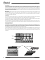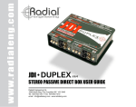
1
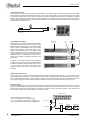
www.radialeng.com
True to the Music
SW8
Owner’s Manual
Eight Channel Auto Switcher • Transformer Isolated
Order No. R800 8100
Radial Engineering Ltd.
1638 Kebet Way, Port Coquitlam BC V3C 5W9
tel: 604-942-1001 • fax: 604-942-1010
email: [email protected] • web: www.radialeng.com
Specifications and appearance are subject to change without notice.
Copyright © 2007 Radial Engineering Ltd.
www.radialeng.com
Radial SW8 Auto-Switcher
Combination Eight Channel Auto Switcher & Transformer Isolated Direct Box
Owner’s Manual
Table of Contents
Page
SW8 Overview........................................................ 1
Features and Functions.......................................... 2
Audio Connections ................................................. 3
Control Connections ............................................... 5
Grounding Options ................................................. 6
Operation................................................................ 7
Signal Flow Block Diagram .................................... 8
Specifications ......................................................... 8
FAQ ........................................................................ 9
Warranty .................................................Back Cover
INTRODUCTION
Congratulations on your purchase of a Radial SW8™ Auto Switcher. The Radial SW8 Auto-Switcher is designed to provide redundant
backup for multi-track playback systems. This manual covers installation and operation of the SW8. We recommend that you take a
few minutes to read through this manual in order to familiarize yourself with the many innovative features incorporated into the SW8.
Inside, you will find important safety features along with tips on how to get the most out of your SW8.
Should you have a questions on applications not covered in this manual, we invite you to log onto the Radial web site at
www.radialeng.com to check the FAQ (Frequently Asked Questions) section for the latest updates. Of course, you can also send us
an email at [email protected].
Radial Engineering Ltd.
1638 Kebet Way, Port Coquitlam BC V3C 5W9
tel: 604-942-1001 • fax: 604-942-1010
email: [email protected] • web: www.radialeng.com
www.radialeng.com
Specifications and appearance are subject to change without notice.
Copyright © 2007 Radial Engineering Ltd.
!
PERFORMANCE DISCLAIMER
The Radial SW8 is a electronic device designed to provide the means to backup other electronic devices. However,
like all electronics, the SW8 itself is not totally immune to malfunction. Because the SW8 is designed to integrate
with other devices to form a complete system, a critical malfunction may not be obvious until the system is asked
to perform. This makes it very important to test your complete playback system before each performance to ensure
your system is working as expected.
Radial Engineering Ltd. will not be held liable for any consequential or inconsequential costs or damages associated
with the use of the SW8. It is understood that connecting, testing and operating the SW8, along with the application
or miss-application, is the sole responsibility of the end user. For more details refer to the Radial limited warranty.
True to the Music
OVERVIEW
The Radial SW8 is an eight channel redundant switcher
designed primarily for live concerts where backing tracks
are used to reinforce the performance. Should the primary
playback machine suffer a failure, the SW8 can switch to a
backup machine either automatically, manually, or by remote
control.
Playback A
Playback B
(Backup)
The SW8 lets you select between two groups of eight audio
inputs and route either group to eight discrete outputs. Input
connections are made with either standard DB25 D-sub
connectors or individual phone jacks to interface with a
variety of audio playback systems. The SW8 has two output
options; a direct thru-put of line-level signals for connection
directly to a mixing console, or eight transformer isolated miclevel outputs allowing connection through a multi-channel
snake system to the PA and FOH console.
The SW8 can operate in three modes; manual, automatic
and remote. Manual switching is accomplished using the front
panel controls or an external latching footswitch. When set to
automatic mode, the SW8 can detect a machine malfunction
and switch to the backup machine to ensure a seamless
performance. Finally, the SW8 can be remotely controlled
by an external automation system using the contact closure
input.
Switching between two 8-track playback machines.
Several SW8 units may be linked together for multi-track
playback systems with more than eight tracks. One SW8
is designated as a master unit and in turn, passes control
signals onto subordinate units through a link connection.
Playback A
Playback B
(Backup)
Playback A
Playback B
(Backup)
Master
Link
Slave
Link
Slave
Tracks.
1-8
Tracks.
9-16
Tracks.
17-24
Switching between two 24-track playback
machines with three linked SW8 units.
Radial Engineering Ltd.
Connection through a mic snake using
the transformer isolated XLR outputs.
SW8 Owner’s Manual
1
True to the Music
FEATURES AND FUNCTIONS
1
2
3
4
5
14
a
6
7
8
9
10
b
11
c
12 13 15
18
16
19
17
20
Front Panel
1. A and B INPUT SELECT with LED - Toggles between the A
and B input groups. Two status LED lights indicate which input
group is active.
2. ALARM LED - Indicates the loss of Tone Track at either the
AUTO SWITCH INPUT or ALT TONE TRACK (channel-1,
group-A) inputs.
3. TONE LED - Indicates the machine tone is present at either
the AUTO SWITCH INPUT or ALT TONE TRACK input.
4. XLR OUTPUTS 1 thru 8 - Mic-level outputs, transformer
isolated to eliminate hum and buzz caused by ground loops.
5. LIFT SWITCH - disconnects pin-1 on the XLR output to
further reduce the possibility of ground loop hum.
Rear Panel
6. GROUP-A and B PHONE INPUTS - Individual connections
for two groups of eight balanced or unbalanced inputs.
7. ALTERNATE TONE TRACK INPUT - Channel-1 of INPUT-A
may be used for the Tone Track when it is recorded on track-1.
This is an alternative to using the AUTO SWITCH INPUT for
the Tone Track.
8. D-SUB DIRECT OUTPUT - Eight channel direct output.
Balanced Tascam pin-out standard.
9. A and B D-SUB INPUTS - Eight channel input connection.
Balanced Tascam pin-out standard.
10. GLOBAL -20dB PAD - Reduces the signal on all channels
going to the transformers to prevent saturation. Has no effect
on the D-SUB DIRECT output. Status LED indicates when the
Global PAD is active.
11. AUTO SWITCH - Consists of three separate items used to set
up the automatic switching mode:
a. AUTO ON - Activates automatic switching mode. Status
LED indicates when Auto mode is active.
2
Radial Engineering Ltd.
12.
13.
14.
15.
b. AUTO SWITCH PHONE INPUT - Dedicated input for
Tone Track signal. Connects to the device supplying
the Tone Track signal such as the master multi-track.
c. THRESHOLD CONTROL - Sets the trigger level for
automatic switching. When Tone Track signal drops
below the threshold level it will trigger the SW8 to
toggle from input group-A to group-B.
FOOT-SW - Remote control input for an external latching
footswitch or automation control system.
CONTACT - Internal relay may be used as a switch to
activate external systems like sirens and strobe lights.
LINK IN & OUT - Used to daisy-chain multiple SW8 units
together for larger systems.
POWER SUPPLY - Connection for the included
15VDC power supply. Cable lock prevents accidental
disconnection.
Internal
16. TONE FILTER SWITCH - Three position low pass filter
switch used to prevent crosstalk between the Tone Track
signal and the program audio.
17. CONN4 XLR - Ribbon cable connector used to re-route
the post-transformer, mic-level signals to the rear D-SUB
connector instead of the front panel XLR jacks.
18. RELAY SWITCHING - Sealed audio relays with gold
contacts route audio through the SW8 without coloration.
19. ISOLATIONS TRANSFORMERS - Radial isolation
transformers eliminate buzz and hum caused by ground
loops.
20. INDIVIDUAL CHASSIS GROUND - Each channel is
equipped with an internal chassis ground switch allowing
custom grounding schemes.
SW8 Owner’s Manual
True to the Music
AUDIO CONNECTIONS
The SW8 is designed to receive line-level signals from two multi-track playback systems. Connection from each multi-track machine is
made with either eight ¼” phone jacks or DB25 D-SUB connectors. Input signals may be +4dB / -10dB, balanced or unbalanced.
¼” Phone Jacks
- +
Ground
Playback B
(Backup)
Playback A
DB25 D-SUB Pin Out
The DB25 connectors use the TASCAM pin-out configuration for eight channel analog audio. See the pin-out chart for reference. This
pin-out chart also appears on the rear panel. NOTE: The lock-down screws used on the D-Sub connectors use “American standard”
(SAE) threads. D-Sub connectors equipped with metric threads should not be used.
Playback B
(Backup)
Female DB-25 Pin-out (Panel View)
13
-
+
G
1 + 2G
-
+
G
3 + 4G
-
G
5 + 6G
+
-
G
+
7 + 8G
1
2
3
Male DB-25 Pin-out (Cable View)
-
+
+
-
!
Playback A
6
G
-
+
+ 7G
G
-
4
+5G
+3G
-
-
+
G
2
G
-
8
13
+1G
American standard SAE
lock-down screws.
Radial Cable Reference
Radial manufactures a range of D-SUB cables that will interface the SW8 with a wide variety of equipment. Available with Radial
Torsion or Mogami EZ-ID multi-pair snake cables in your choice of end termination and length.
RADIAL 8-CHANNEL D-SUB CABLE
MOGAMI 8-CHANNEL D-SUB CABLE
D-Sub ~ 8 x XLR - Male
Order #
R461 0808 03
R461 0816 03
R461 0824 03
D-Sub ~ 8 x Male XLR
Order #
R451 0808 03
R451 0816 03
R451 0824 03
L
8’
16’
24’
L
8’
16’
24’
D-Sub ~ 8 x XLR - Female
R461 0808 00
8’
R461 0816 00
16’
R461 0824 00
24’
D-Sub ~ 8 x Female XLR
R451 0808 00
8’
R451 0816 00
16’
R451 0824 00
24’
D-Sub ~ 8 x ¼” TRS
R461 0808 01
R461 0816 01
R461 0824 01
8’
16’
24’
D-Sub ~ 8 x ¼” TRS
R451 0808 01
R451 0816 01
R451 0824 01
8’
16’
24’
D-Sub ~ D-Sub
R461 0808 02
R461 0816 02
R461 0824 02
8’
16’
24’
D-Sub ~ D-Sub
R451 0808 02
R451 0816 02
R451 0824 02
8’
16’
24’
3
Radial Engineering Ltd.
SW8 Owner’s Manual
True to the Music
Audio Outputs
The SW8 offers two audio outputs; the line-level DB25 output connector and the front panel mic-level XLR jacks. Which output you
choose to use will depend on where the SW8 is set up. For instance, the DB25 output will typically be used at the FOH mix position to
feed line-level signals to the console while the XLR outputs would feed mic-level signals to the on-stage mic snake. The DB25 direct
thru-put and the mic-level XLR outputs can be used at the same time should you want to connect two mixing consoles using different
signal formats. For example, the DB25 output may be connected to the on-stage monitor console while the XLR outputs are connected
to the FOH console through the mic snake.
DB25 Output
The rear panel DB25 connector is a direct thru-put connection providing a duplicate of the input signal. The signal path from the
inputs to the DB25 direct thru-put is 100% passive with no active electronics to color the sound. The audio signals only cross the
gold contacts of the sealed relays before reaching the DB25 output connector. Use the rear panel DB25 connector when the SW8 is
connected to the line-level console inputs.
XLR Outputs
The front panel XLR jacks produce a balanced, mic-level signal and are transformer isolated to eliminate buzz and hum caused by
ground loops. The mic-level outputs allow the SW8 to interface with mic splitter snakes and console mic-preamps.
If you hear distortion from the XLR outputs it is likely that the multi-track output level is overloading the transformers. The GLOBAL
PAD switches in a -20dB PAD on all eight channels to protect against overloading the transformer.
Each channel features a ground LIFT switch that disconnects the pin-1 signal ground at the XLR outputs. It may be used on a perchannel basis to accommodate specific grounding needs. Typically this will be set to lift the ground (pushed in) so the transformer can
decouple the signal grounds.
Internal Ribbon Connector
An internal ribbon connector allows the SW8 to route the eight transformer isolated mic-level outputs to the rear panel DB25 connector.
This allows mic-level connections to be made on the rear panel instead of the front XLR jacks. This modification will disconnect the
front XLR jacks and the SW8 will only be able to output mic-level signals (no direct thru-put is available in this mode). Note that after
this modification the front panel LIFT switches will continue to function as normal.
To access the internal ribbon connector remove the top panel. Locate the ribbon cable for the DB25 Direct output. Gently remove the
ribbon connector from the circuit board and plug it into CONN4 marked “XLR OUT” on the circuit board. The red stripe on the ribbon
cable should be on the same side as the rear panel and the notch on the connector should match with the notch silk screened on the
circuit board.
Direct out
ribbon cable.
CONN4
XLR OUT
Notch
4
Radial Engineering Ltd.
SW8 Owner’s Manual
True to the Music
CONTROL CONNECTIONS
The SW8 may be toggled three different ways; manually via the front panel controls, remotely through a contact closure system or
latching footswitch, or automatically with a Tone Track signal from a multi-track or synchronizer. This section describes the process
for each method.
Manual Switching
No control connections are needed if you plan to manually toggle the SW8 from the front panel INPUT
SELECT A/B switch. The SW8 will toggle to input group-B when the switch is depressed.
Remote Switching
The FOOT-SW ¼” phone jack on the rear panel allows the SW8 to be controlled with a remote contact closure system or latching
footswitch. Closing the circuit connected to the FOOT-SW jack produces the same result as depressing the SELECT A/B switch on the
front panel. Because the FOOT-SW jack is a common contact closure type input it can be connected to an automation system or MIDI
contact closure device. The front panel SELECT A/B switch is defeated when a plug is inserted into the FOOT-SW jack. The status
LED indicators on the front panel will help you to keep track of the active input group when the SW8 is controlled remotely.
SPST
Latching Switch
Automatic Switching
In order for the SW8 to automatically switch to a backup machine, an audio signal
must be sent to the THRESHOLD detection circuit. One way this can be accomplished
is by recording a Tone Track onto the master multi-track connected to input group-A.
Alternatively, the tone track can originate from a dedicated synchronizer or automation
system.
If the Tone Track signal should drop below a preset threshold level, indicating a machine
failure, the SW8 will automatically switch to the backup machine connected to the input
group-B. The Tone Track signal can be any constant signal. We have tested the SW8
with a 1kHz. sinewave tone and SMPTE time code with excellent results. Note that the
SW8 does not “read” SMPTE time code but the audio carrier signal SMPTE generates
is suitable as a Tone Track for the THRESHOLD detection circuit. The THRESHOLD
level control is used to set the point where the SW8 toggles to input group-B and may be
adjusted to suit a wide range of track levels.
Tone Track
Threshold
Switch Point
Connection of the Tone Track signal into the SW8 can be made in three ways:
1
Channel-1 DB25 (Group-A): If the Tone Track signal is recorded onto track-1 it may be connected to channel-1 of group-A at the
DB25 connector.
2
Channel-1 ¼” Phone (Group-A): The Tone Track signal may also be connected to channel-1 at the ¼” phone jack.
Channel-1 is internally routed to the THRESHOLD detection circuit. This is true for both the 1/4” phone and D-SUB inputs and is
intended to be a convenient way to connect the Tone Track when it is recorded on track-1 of the master multi-track. The internal
routing of channel-1 to the detection circuit is interrupted when a plug is inserted into the dedicated AUTO SWITCH INPUT
allowing channel-1 to be used for program audio instead of Tone Track.
3
Auto Switch ¼” Phone Jack: If the Tone Track signal is coming from another device other than the master playback machine it can
be connected to the dedicated AUTO SWITCH ¼” phone jack. The advantage to using the dedicated AUTO SWITCH input is that
it frees up channel-1 for use as an audio channel giving you a full eight channels of A/B switching.
DB25 Input Group-A
13
1
-
G
G
1 + 2-
+
-
G
G
3 + 4-
+
-
G
G
5 + 6-
+
-
G
G
+
7 + 8-
2
1
2
3
Threshold
Level
Select Toggle
In-A / In-B
3
Radial Engineering Ltd.
SW8 Owner’s Manual
5
True to the Music
Contact Closure Output
This jack accesses an internal relay that acts as an ON/OFF switch for an external circuit. The relay is linked to the front panel ALARM
LED. Normally, the CONTACT CLOSURE OUTPUT relay is in an “open” state preventing current from flowing through the external
circuit. When the SW8 detects a loss of Tone Track signal the front panel ALARM LED illuminates and the CONTACT CLOSURE
OUTPUT relay closes allowing current to flow through the external circuit. An example of an external circuit would be a strobe light or
siren to notify the engineer that the Tone Track signal has disappeared. The CONTACT OUTPUT is designed to work with low voltage
systems between 5 and 24 volts DC.
-
+
DC Power Supply
5-12 volts
Linking SW8 Units Together
Several SW8 units can be linked together to accommodate
multi-track systems larger than eight channels. The first
SW8 is designated as the “master” and controls the linked
units as “slaves”. The THRESHOLD control on the master
SW8 adjusts the point at which all units toggle to input
group-B. The A/B SELECT switch on the master unit will
toggle all linked SW8 units. If a remote contact closure
is used, it should be connected to the master SW8 unit’s
CONTACT INPUT. If an external alarm circuit is used, it
should be connected to the CONTACT OUTPUT on the
master SW8.
Linking two or more SW8 units together is accomplished
by simply connecting the LINK OUT on the master SW8 to
the LINK IN on the slaves. Use a standard single conductor
¼” phone cable (¼” guitar cable) to link units. You can
continue the LINK OUT connection to expand the system
as needed.
Alternate Tone
Track Input
Tone
Track
External
Alarm
Master
Remote Contact
Closure
Slave 1
Slave 2
Internal Chassis Ground Lift
All connectors are 100% isolated, allowing chassis and signal grounds to be kept separate. However, an internal switch for each
channel is provided to connect the pin-1 cable shields to the chassis without modifying the SW8. By default, this switch is factory set to
open or “lifted” allowing the chassis to “float” ungrounded. Should a specific grounding scheme require the cable shields to be bonded
to the chassis, simply set this switch to closed (pushed in position). The switch may be accessed by removing the top cover.
Internal Tone Filter
The SW8 is equipped with a low pass filter that may be inserted into the Tone Track signal path to prevent cross-talk from loud Tone
Track signals from bleeding into the program audio. The filter is controlled by an internal three position switch that can be accessed
through a hole in the top using a small screwdriver or “tweaker”. The tone filter is factory set to OFF or bypass. In most cases it will not
be necessary to engage the filter when feeding a Tone Track to the SW8.
DB25 Input Group-A
13
The internal switch has three positions:
• Off - the low pass filter is not in the signal path.
• Low - high frequencies are reduced by -3dB @ 1k Hz.
• High - high frequencies are reduced by -3dB @ 470 Hz.
-
G
G
1 + 2-
+
-
G
G
3 + 4-
+
-
G
G
5 + 6-
+
-
G
G
+
7 + 8-
Channel-1 ¼”
Tone Filter
High
Threshold
Detection
Select Toggle
In-A / In-B
AUTO SWITCH
Low
Off
6
Radial Engineering Ltd.
SW8 Owner’s Manual
True to the Music
OPERATION
Manual Mode
In this mode the SW8 may be toggled with the front panel INPUT SELECT switch or with an external latching footswitch connected
to the CONTACT INPUT jack. If the SW8 does not toggle when either the front panel AB SELECT switch or external footswitch is
depressed ensure the AUTO ON switch is in the outward position and its LED is not illuminated.
Manual Mode with Alarm
In this mode the Tone Track signal is used to trigger an external alarm system in order to prompt the operator to manually switch to
the backup machine.
1. Record a Tone Track signal onto track-1 of your master multi-track.
2. Connect track-1 to either INPUT-A (channel-1) or the AUTO SWITCH input jack.
3. Ensure the AUTO ON switch is in the outward position and the LED is not illuminated.
4. Connect an appropriate alarm circuit to the CONTACT OUTPUT jack as described in the previous section.
5. While sending the Tone Track signal to the SW8, adjust the THRESHOLD control to find the level where the front panel ALARM LED
illuminates. Set the THRESHOLD control above this point.
6. Test the system by stopping playback on your master multi-track. When no Tone Track signal is fed to the SW8 the ALARM LED will
illuminate and the CONTACT CLOSURE OUTPUT relay closes, triggering the external circuit alarm.
Automatic Mode
In this mode the Tone Track signal is used to trigger the SW8 to switch to INPUTS-B. To activate automatic switching, depress the
AUTO ON switch and ensure the LED is illuminated. Auto switching works by sensing the Tone Track signal. A loss of Tone Track
signal will cause the SW8 to toggle to INPUTS-B.
1. Depress AUTO ON switch and ensure the LED is illuminated.
2. Record a Tone Track signal onto track-1 of your master multi-track.
3. Connect track-1 to either INPUT-A (channel-1) or the AUTO SWITCH input jack.
4. While sending the Tone Track signal to the SW8, adjust the THRESHOLD control to find the level where the SW8 toggles to INPUTB. Set the THRESHOLD control above this point.
5. Test the system by stopping playback on your master multi-track. The SW8 should toggle to INPUTS-B.
Automatic Mode with Alarm
In this mode the Tone Track signal is used to toggle the SW8 and to trigger an alarm circuit connected to the CONTACT OUTPUT
jack.
1. Depress AUTO ON switch and ensure the LED is illuminated.
2. Record a Tone Track signal onto track-1 of your master multi-track.
3. Connect track-1 to either the SW8 channel-1 or the AUTO SWITCH input.
4. Connect an appropriate alarm circuit to the CONTACT OUTPUT jack as described in the previous section.
5. While sending the Tone Track signal to the SW8, adjust the THRESHOLD control to find the level where the SW8 toggles to INPUTB and the alarm is triggered. Set the THRESHOLD control a little above this point.
6. Test the system by stopping playback on your master multi-track. The SW8 should toggle to INPUTS-B and trigger the external
alarm circuit.
!
TESTING THE SYSTEM
Test the system before each performance. It is the sole responsibility of the user to determine if the system is
performing as expected. Therefore it is very important to devise a testing procedure that takes into account the
weakest links in the signal and control chains. Your test points should always be up-stream of those links in
order to ensure every piece of equipment in the playback system is functioning properly. Due to the unlimited
possibilities of how the SW8 can be used we can not take any responsibility for the use, applied application,
miss-application or malfunction of the SW8 other than what is stated in the Radial warranty. If you are at all
uncomfortable or feel the SW8 is not well suited to the task at hand please return the unit to your dealer. Please
read the Radial warranty and performance disclaimer for details.
Radial Engineering Ltd.
SW8 Owner’s Manual
7
True to the Music
BLOCK DIAGRAM
SW8 Specifications
Input-A & B
1/4” phone:
D-Sub:
Input impedance:
8
Radial Engineering Ltd.
TRS balanced +4dB / unbalanced -10dB
DB25 balanced +4dB / unbalanced -10dB
140K ohms typical (without Global PAD)
10k ohms typical (with Global PAD)
Direct Output
Type:
Switching Time:
Passive balanced signal path
3ms maximum @ 20°C
XLR Output
Frequency response:
Total harmonic distortion:
Output impedance:
Output:
PAD:
20Hz to 20kHz +/- 2.5dB
0.01 % from 20Hz to 20kHz
600 ohms
-60dB (mic level) balanced (pin-2 hot)
-20dB ( Global - all channels)
Foot-SW
1/4” phone:
Contact closure to ground
Contact Relay
1/4” phone:
5-24 VDC relay circuit
Dimensions:
9” x 6.5” x 1.75” (1RU)
482.6mm x 165.1mm x 44.45mm
Weight:
7.2 lbs. (3.26 kg.)
External Power supply:
Output 15 VDC @ 400 mA
SW8 Owner’s Manual
True to the Music
FREQUENTLY ASKED QUESTIONS
Q: What testing procedures are recommended?
A: It will greatly depend on the system as a whole. The SW8 can be interfaced in several ways so the best recommendation is to devise
your own testing procedure that takes into account all the pieces of the system that will affect playback should one component
fail.
Q: Can I use the SW8 to switch other audio gear?
A: You can use the SW8 to switch any line-level audio application. One example would be switching between two eight bus consoles.
This would be advantageous when two FOH consoles are used, one for the warm-up act and one for the headliner. The SW8 can
be used to connect each console to the speaker management DSP processor or drive rack.
Q: Can I use the SW8 to switch one device between two inputs?
A: The SW uses a passive signal path from the ¼” and DB25 inputs to the DB25 direct output. Therefore these connectors can be used
to route audio signals in either direction. However, this does not apply to the front panel XLR outputs. The XLR jacks can only be
used as mic-level outputs because of the bridging transformers.
Q: Can the SW8 be used to switch a backup keyboard setup.
A: Yes. The SW8 would allow you quickly switch between main and backup keyboard systems. The SW8 could provide either a direct
output to a keyboard mixer or XLR mic-level outputs to an on-stage snake system, or both. Several SW8 switchers can be linked
to accommodate as many instrument inputs as needed.
Q: Can I overload the SW8?
A: The direct output can not be overloaded as it is a hard-wired connection through the switching relays. However, the transformer
isolated XLR outputs can be overloaded. The GLOBAL PAD feature is provided to prevent transformer saturation.
Q: Why doesn’t the SW8 have an OFF/ON switch?
A: Because the SW8 features a passive signal path, audio will always pass through even when the SW8 is de-energized. We
eliminated a power switch and added a power supply cable clamp to lower the risks of using the SW8 in a live performance.
Q: Why would I want to use the XLR outputs?
A: The XLR outputs are transformer isolated, which is the best way to eliminate buzz and hum caused by ground loops. You would
want to use the XLR outputs when connecting to a console that may pose a ground loop problem.
Q: What is a ground loop?
A: A ground loop is created when an audio system has multiple paths to ground, often called earth. This situation can occur when two
AC powered audio devices, such as two mixing consoles, are plugged into different power circuits and connected together via a
signal cable. Both audio devices have a path to ground through the third prong on the AC-mains cable. The signal cable completes
the loop by connecting the devices together through the signal cable’s shield (figure 1).
Once the loop is complete there is the electrical potential for DC voltage to flow through it. This potential is caused by the interaction
between devices with different ground voltage references and allows unwanted spurious current to flow through the shields of the
signal cables. This flow of DC voltage creates noise in the signal wires through induction and capacitance at the base frequency
of 50 or 60 Hz (hum) and the upper harmonics of 120 Hz, 240 Hz, etc. (buzz). Isolating or decoupling the audio signal with a
transformer at a point between the two devices is the best way to block the unwanted flow of ground-potential currents and
eliminate hum and buzz in audio systems (figure 2).
Transformer Isolation
Ground Loop Path
Figure 1
Figure 2
Earth
Radial Engineering Ltd.
Earth
SW8 Owner’s Manual
9
RADIAL ENGINEERING LTD. (“Radial”) warrants this product to be free from defects in material and workmanship and will remedy any such defects free of charge according to the terms of this warranty. Radial will repair
or replace (at its option) any defective component(s) of this product (excluding finish and wear and tear on components under normal use) for a period of three (3) years from the original date of purchase. In the event that a
particular product is no longer available, Radial reserves the right to replace the product with a similar product
of equal or greater value. To make a request or claim under this limited warranty, the product must be returned
prepaid in the original shipping container (or equivalent) to Radial or to an authorized Radial repair center and you
must assume the risk of loss or damage. A copy of the original invoice showing date of purchase and the dealer
name must accompany any request for work to be performed under this limited warranty. This limited warranty
shall not apply if the product has been damaged due to abuse, misuse, misapplication, accident or as a result of
service or modification by any other than an authorized Radial repair center.
THERE ARE NO EXPRESSED WARRANTIES OTHER THAN THOSE ON THE FACE HEREOF AND DESCRIBED ABOVE. NO WARRANTIES WHETHER EXPRESSED OR IMPLIED, INCLUDING BUT NOT LIMITED TO, ANY IMPLIED WARRANTIES OF MERCHANTABILITY OR FITNESS FOR A PARTICULAR PURPOSE
SHALL EXTEND BEYOND THE RESPECTIVE WARRANTY PERIOD DESCRIBED ABOVE OF THREE YEARS.
RADIAL SHALL NOT BE RESPONSIBLE OR LIABLE FOR ANY SPECIAL, INCIDENTAL OR CONSEQUENTIAL
DAMAGES OR LOSS ARISING FROM THE USE OF THIS PRODUCT. THIS WARRANTY GIVES YOU SPECIFIC LEGAL RIGHTS, AND YOU MAY ALSO HAVE OTHER RIGHTS, WHICH MAY VARY DEPENDING ON
WHERE YOU LIVE AND WHERE THE PRODUCT WAS PURCHASED.
Radial Engineering Ltd.
1638 Kebet Way, Port Coquitlam BC V3C 5W9
tel: 604-942-1001 • fax: 604-942-1010
email: [email protected] • web: www.radialeng.com
Radial SW8 Owner’s Manual - Part #R870-1192-00 • V1.0
Specifications and appearance are subject to change without notice.
www.radialeng.com
RADIAL ENGINEERING LTD.
3 YEAR TRANSFERABLE WARRANTY