1
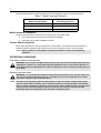
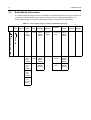
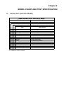
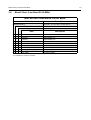
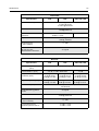
Professional Radio
GM300 Series
Basic Service Manual
68P64115B51
Issue: July 2000
ii
Computer Software Copyrights
The Motorola products described in this manual may include copyrighted Motorola computer programs stored
in semiconductor memories or other media. Laws in the United States and other countries preserve for
Motorola certain exclusive rights for copyrighted computer programs, including the exclusive right to copy or
reproduce in any form, the copyrighted computer program. Accordingly, any copyrighted Motorola computer
programs contained in the Motorola products described in this manual may not be copied or reproduced in
any manner without the express written permission of Motorola. Furthermore, the purchase of Motorola
products shall not be deemed to grant, either directly or by implication, estoppel or otherwise, any license
under the copyrights, patents or patent applications of Motorola, except for the normal non-exclusive
royalty-free license to use that arises by operation of law in the sale of a product.
iii
SAFETY INFORMATION
Read this information before using your radio.
SAFE AND EFFICIENT OPERATION OF MOTOROLA TWO-WAY RADIOS
This document provides information and instructions for the safe and efficient operation of Motorola
Portable and Mobile Two-Way Radios. The information provided in this document supersedes the
general safety information contained in user guides published prior to 1 January 1998.
For information regarding radio use in hazardous areas, please refer to the Factory Mutual (FM)
approval manual supplement.
EXPOSURE TO RADIO FREQUENCY ENERGY
Your Motorola Two-Way Radio, which generates and radiates radio frequency (RF) electromagnetic
energy (EME), is designed to comply with the following National and International Standards and
Guidelines regarding exposure of human beings to radio frequency electromagnetic energy:
Federal Communications Commission Report and Order No. FCC 96-326 (August 1996)
American National Standards Institute (C95.1 - 1992)
National Council on Radiation Protection and Measurements (NCRP-1986)
International Commission on Non-Ionizing Radiation Protection (ICNRP- 1986)
European Committee for Electrotechnical Standardization (CENELEC):
ENV 50166-1 1995 E
Human exposure to electromagnetic fields Low
frequency (0 Hz to 10 kHz)
- ENV 50166-2 1995 E
Human exposure to electromagnetic fields High
frequency (10 kHz to 300 GHz)
- Proceedings of SC211/B
1996
“Safety Considerations for Human Exposure to
EMFs from Mobile Telecommunication Equipment
(MTE) in the Frequency Range 30MHz - 6 GHz.”
(EMF - Electro-Magnetic Fields)
To assure optimal radio performance and to ensure that your exposure to radio frequency
electromagnetic energy is within the guidelines in the above standards, always adhere to the following
procedures:
ELECTROMAGNETIC INTERFERENCE/COMPATIBILITY
NOTE Nearly every electronic device is susceptible to electromagnetic interference (EMI) if
inadequately shielded, designed, or alternately configured for electromagnetic compatibility.
To avoid electromagnetic interference and/or compatibility conflicts, turn off your radio in any facility
where posted notices instruct you to do so. Hospital or health facilities may be using equipment that
is sensitive to external RF energy.
When instructed to do so, turn off your radio when on board an aircraft. Any use of a radio must be
in accordance with airline regulations or crew instructions.
Mobile Radio Operation and EME Exposure
To assure optimal radio performance and that human exposure to radio frequency electromagnetic
energy is within the guidelines referenced in this document, transmit only when people inside and
outside the vehicle are at least the minimum distance away from a properly installed,
externally-mounted antenna.
iv
The table below lists the minimum distance for several different ranges of rated radio power.
Table 1 Rated Power and Distance
Rated Power of Vehicle-Installed
Mobile Two-Way Radio
Minimum Distance from
Transmitting Antenna
7 to 15 Watts
30.5 cm (1 Foot)
16 to 50 Watts
61 cm (2 Feet)
More than 50 Watts
91.5 cm (3 Feet)
Mobile Antenna Installation
Install the vehicle antenna external to the vehicle and in accordance with:
a. The requirements of the antenna manufacturer/supplier
b.
Instructions in the radio installation manual.
Control Station Operation
When radio equipment is used to operate as a control station, it is important that the antenna be
installed outside the building and away from places where people may be in close proximity.
NOTE Refer to Table 1 for rated power and minimum distance values for transmitting
antennas.
OPERATIONAL WARNINGS
Potentially explosive atmospheres
!
WARNING: Turn off your Two-Way radio when you are in any area with a potentially explosive
atmosphere, unless it is a radio type especially qualified for use in such areas. Sparks in a
potentially explosive atmosphere can cause an explosion or fire resulting in bodily injury or
even death.
Blasting caps and areas
!
NOTE
WARNING: To avoid possible interference with blasting operations, turn off your radio when
you are near electrical blasting caps. In a “blasting area” or in areas posted “turn off twoway radio”, obey all signs and instructions.
The areas with potentially explosive atmospheres referred to above include fuelling areas
such as: below decks on boats; fuel or chemical transfer or storage facilities; areas where
the air contains chemicals or particles, such as grain, dust or metal powders; and any other
area where you would normally be advised to turn off your vehicle engine. Areas with
potentially explosive atmospheres are often but not always posted.
v
Table of Contents
SAFETY INFORMATION........................................................................................iii
Chapter 1
INTRODUCTION
1.0 Scope of Manual ..................................................................................................1-1
2.0 Warranty and Service Support.............................................................................1-1
2.1 Warranty Period and Return Instructions .......................................................1-1
2.2 After Warranty Period .....................................................................................1-1
2.3 European Radio Support Centre (ERSC).......................................................1-2
2.4 Piece Parts .....................................................................................................1-2
2.5 Technical Support...........................................................................................1-3
3.0 Radio Model Information......................................................................................1-4
Chapter 2
1.0
2.0
3.0
2.4
MODEL CHART AND TEST SPECIFICATION
Model Chart (UHF 403-470 MHz) ........................................................................2-1
Model Chart (VHF 136-174 MHz) ........................................................................2-2
Model Chart (Low Band 29-50 MHz) ...................................................................2-3
Specifications ......................................................................................................2-4
Chapter 3
MAINTENANCE
1.0 Introduction ..........................................................................................................3-1
2.0 Preventive Maintenance ......................................................................................3-1
2.1 Inspection .......................................................................................................3-1
2.2 Cleaning Procedures ......................................................................................3-1
3.0 Safe Handling of CMOS and LDMOS Devices ....................................................3-2
4.0 Repair Procedures and Techniques — General ..................................................3-3
5.0 Disassembling and Reassembling the Radio — General ....................................3-3
6.0 Radio Disassembly - Detailed..............................................................................3-4
6.1 Control Head Removal ...................................................................................3-4
6.2 Top Cover Removal........................................................................................3-5
6.3 Transceiver Board Removal ...........................................................................3-6
6.4 Disassembly of Control Head - GM340 (without display) ...............................3-7
6.5 Disassembly of Control Heads - GM360 and GM380 (with display) ..............3-8
7.0 Radio Assembly ...................................................................................................3-9
7.1 Control Head - GM340 ...................................................................................3-9
7.2 Control Heads - GM360 and GM380..............................................................3-9
7.3 Radio Chassis and Transceiver Board .........................................................3-10
7.4 Control Head Fitting......................................................................................3-10
vi
8.0 Radio Exploded Mechanical Views and Parts Lists ........................................... 3-11
8.1 Radio Assembly - 25W Models .................................................................... 3-11
8.2 Radio Assembly - 60W Models .................................................................... 3-12
8.3 Control Head - GM340 ................................................................................. 3-13
8.4 Control Head - GM360 ................................................................................. 3-14
8.5 Control Head - GM380 ................................................................................. 3-15
9.0 Service Aids....................................................................................................... 3-16
10.0 Test Equipment.................................................................................................. 3-17
11.0 Programming/Test Cable - RKN4083_ .............................................................. 3-18
Chapter 4
TRANSCEIVER PERFORMANCE TESTING
1.0 General ................................................................................................................ 4-1
2.0 Setup ................................................................................................................... 4-1
3.0 RF Test Mode ...................................................................................................... 4-2
Chapter 5
RADIO TUNING AND PROGRAMMING
1.0 Introduction .......................................................................................................... 5-1
2.0 CPS Programming Setup .................................................................................... 5-1
3.0 Radio Tuning Setup ............................................................................................. 5-3
3.1 Initial Test Equipment Control Settings .......................................................... 5-3
Chapter 6
POWER UP SELF-TEST
1.0 Error Codes ......................................................................................................... 6-1
Chapter 1
INTRODUCTION
1.0
Scope of Manual
This manual is intended for use by service technicians familiar with similar types of equipment. It
contains service information required for the equipment described and is current as of the printing
date. Changes which occur after the printing date may be incorporated by a complete Manual
revision or alternatively as additions.
NOTE Before operating or testing these units, please read the Safety Information Section in the
front of this manual.
2.0
Warranty and Service Support
Motorola offers long term support for its products. This support includes full exchange and/or repair
of the product during the warranty period, and service/ repair or spare parts support out of warranty.
Any "return for exchange" or "return for repair" by an authorised Motorola Dealer must be
accompanied by a Warranty Claim Form. Warranty Claim Forms are obtained by contacting an
Authorised Motorola Dealer.
2.1
Warranty Period and Return Instructions
The terms and conditions of warranty are defined fully in the Motorola Dealer or Distributor or
Reseller contract. These conditions may change from time to time and the following notes are for
guidance purposes only.
In instances where the product is covered under a "return for replacement" or "return for repair"
warranty, a check of the product should be performed prior to shipping the unit back to Motorola.
This is to ensure that the product has been correctly programmed or has not been subjected to
damage outside the terms of the warranty.
Prior to shipping any radio back to the appropriate Motorola warranty depot, please contact
Customer Resources (Please see page 2 and page 3 in this Chapter). All returns must be
accompanied by a Warranty Claim Form, available from your Customer Services representative.
Products should be shipped back in the original packaging, or correctly packaged to ensure no
damage occurs in transit.
2.2
After Warranty Period
After the Warranty period, Motorola continues to support its products in two ways.
1.
Motorola's Radio Aftermarket and Accessory Division (AAD) offers a repair service to both
end users and dealers at competitive prices.
2.
AAD supplies individual parts and modules that can be purchased by dealers who are
technically capable of performing fault analysis and repair.
1-2
2.3
INTRODUCTION
European Radio Support Centre (ERSC)
The ERSC Customer Information Desk is available through the following service numbers:
Austria:
06 60 75 41
Italy:
16 78 77 387
Belgium:
08 00 72 471
Luxemburg:
08 00 23 27
Denmark:
80 01 55 72
Netherlands:
60 22 45 13
Finland:
08 00 11 49 10
Norway:
80 01 11 15
France:
05 90 30 90
Portugal:
05 05 49 35 70
Germany:
01 30 18 75 24
Spain:
90 09 84 902
Greece:
00 80 04 91 29 020
Sweden:
02 07 94 307
UK :
08 00 96 90 95
Switzerland:
1 55 30 82
Ireland:
18 00 55 50 21
Iceland:
80 08 147
Or dial Customer Care Centre:
Tel: +49 6128 70 2164
Please use these numbers for repair enquiries only.
2.4
Piece Parts
Some replacement parts, spare parts, and/or product information can be ordered directly. If a
complete Motorola part number is assigned to the part, it is available from Motorola Radio
Aftermarket and Accessory Division (AAD). If no part number is assigned, the part is not normally
available from Motorola. If the part number is appended with an asterisk, the part is serviceable by
Motorola Depot only. If a parts list is not included, this generally means that no user-serviceable
parts are available for that kit or assembly.
All part orders should be directed to :
Motorola GmbH
European Parts Department
65232 Taunusstein
Germany.
Warranty and Service Support
2.5
1-3
Technical Support
Motorola Product Services is available to assist the dealer/distributors in resolving any malfunctions
which may be encountered.
UK/Ireland - Richard Russell
Telephone: +44 (0) 1256 488 082
Fax: +44 01256 488 080
Email: [email protected]
Central/East Europe - Siggy Punzenberger
Telephone: +49 (0) 6128 70 2342
Fax: +49 (0) 6128 95 1096
Email: [email protected]
Northern Europe - Bjorn Rambert
Telephone: +46 8 735 9282
Fax: +46 8 735 9280
Email: [email protected]
Germany
Telephone: +49 (0) 6128 70 2266
Fax: +49 (0) 6128 95 1685
Email: [email protected]
France - Lionel Lhermitte
Telephone: +33 1 6929 5722
Fax: +33 1 6929 5904
Email: [email protected]
Italy - Ugo Gentile
Telephone: +39 0 2822 0325
Fax: +39 0 2822 0334
Email: [email protected]
Africa & Middle East - Ralph Schubert
Telephone: +33 (0)4 4230 5887
Fax: +33 (0)4 4230 4784
Email: [email protected]
1-4
3.0
INTRODUCTION
Radio Model Information
The model number and serial number are located on a label attached to the back of your radio. You
can determine the RF output power, frequency band, protocols, and physical packages. The
example below shows one portable radio model number and its specific characteristics.
Table 1-1 Radio Model Number (Example: MDM25KHC9AN1AE)
Type of Model
Unit
Series
M
25
Power
Level
Physical
Packages
Channel
Spacing
Protocol
K
VHF
(136174MHz)
H
1-25W
C
GM140
GM340
GM640
9
Programmable
R
K
UHF1 40-60W
(403470MHz)
B
LB1
(29.736.0MHz)
Feature
Level
Model
Revision
Model
Package
AA
Conventional
MDC
1
GM140
GM340
GM640
A
E
F
GM160
GM360
GM660
AN
5 Tone
5
GM160
GM360
GM660.
N
GM380
GM1280
CK
MPT
8
GM380
GM1280
M = Mobile
MD = Motorola Internal Use
MD
Freq.
Band
C
LB2
(36.042.0MHz)
D
LB3
(42.0-50.0
MHz)
Chapter 2
MODEL CHART AND TEST SPECIFICATION
1.0
Model Chart (UHF 403-470 MHz)
GM Series UHF 403-470 MHz
Model
MDM25RHC9AN1_E
Description
GM340, 403-470 MHz, 1-25W, 6 Ch
MDM25RHF9AN5_E
GM360, 403-470 MHz, 1-25W, 255 Ch
MDM25RHN9AN8_E
GM380, 403-470 MHz, 1-25W, 255 Ch
Item
X
X
X
X
X
GCN6112_
Control Head GM340
GCN6120_
Control Head GM360
GCN6121_
Control Head GM380
IMUE6015_
Tanapa GM340
IMUE6015_
Tanapa GM360
X
IMUE6038_
Tanapa GM380
X
ENBN4056_
Packaging, Waris Mobile
X
X
Description
X
X
X
GLN7324_
Low Profile Mounting Trunion
X
X
X
HKN4137_
12V Power Cable 1-25W
X
X
X
MDRMN4025_
Enhanced Compact Microphone
6864110B80
User Guide, GM340
6864110B81
User Guide, GM360
6864110B82
User Guide, GM380
X
X
X
X = Indicates one of each is required
2-2
MODEL CHART AND TEST SPECIFICATION
2.0
Model Chart (VHF 136-174 MHz)
GM Series VHF 136-174 MHz
Model
MDM25KHC9AN1_E
Description
GM340, 136-174 MHz, 1-25W, 6 Ch
MDM25KHF9AN5_E
GM360, 136-174 MHz, 1-25W, 255 Ch
MDM25KHN9AN8_E
GM380, 136-174 MHz, 1-25W, 255 Ch
Item
X
X
X
X
X
Description
GCN6112_
Control Head GM340
GCN6120_
Control Head GM360
GCN6121_
Control Head GM380
IMUD6013_
Tanapa GM340
IMUD6013_
Tanapa GM360
X
IMUD6024_
Tanapa GM380
X
X
X
ENBN4056_
Packaging, Waris Mobile
X
X
X
GLN7324_
Low Profile Mounting Trunion
X
X
X
HKN4137_
12V Power Cable 1-25W
X
X
X
MDRMN4025_
Enhanced Compact Microphone
6864110B80
User Guide, GM340
6864110B81
User Guide, GM360
6864110B82
User Guide, GM380
X
X
X
X = Indicates one of each is required
Model Chart (Low Band 29-50 MHz)
3.0
2-3
Model Chart (Low Band 29-50 MHz)
GM Series Low Band 29-50 MHz
Model
MDM25BKF9AN5_E
Description
GM360 LB1, 29.0-36.0 MHz, 40-60W, 255 Ch
MDM25CKF9AN5_E
GM360 LB2, 36.0-42.0 MHz, 40-60W, 255 Ch
MDM25DKF9AN5_E
GM360 LB3, 42.0-50.0 MHz, 40-60W, 255 Ch
Item
X
X
X
Description
GCN6120_
Control Head, GM360
IMUB6003_
Tanapa GM360, LB1
IMUB6004_
Tanapa GM360, LB2
X
IMUB6005_
Tanapa GM360, LB3
X
X
X
X
X
ENBN4056_
Packaging, Waris Mobile
X
X
X
HKN9402_
12V Power Cable
X
X
X
MDRMN4025_
Enhanced Compact Microphone
X
X
X
RLN4774_
3 Point Mount
X
X
X
6864110B81_
User Guide, GM360
X = Indicates one of each is required
2-4
2.4
MODEL CHART AND TEST SPECIFICATION
Specifications
General
Specification
Frequency Range:
Frequency Stability
(-30°C to +60°C, 25°C Ref.)
VHF
UHF
LB1, LB2, LB3
136-174 MHz
403-470 MHz
29.7-36.0 MHz
36.0-42.0 MHz
42.0-50.0 MHz
±2.5 PPM
±2 PPM
±5.0 PPM
Channel Capacity:
GM340 - 6
GM360 - 255
GM380 - 255
Channel Spacing:
12.5/20/25 kHz
Power Output:
Power Supply:
1-25W
1-25W
40-60W
13.2Vdc (10.8 - 15.6 Vdc) negative vehicle ground
Dimensions (L X W X H)
UHF/VHF 1-25W
GM340
177mm X 176mm X 56mm (add 8mm for Volume Knob)
(6.97” X 6.93” X 2.2” - add 0.3” for Volume Knob)
GM360
186mm X 179mm X 59mm (add 9mm for Volume Knob)
(7.32” X 7.05” X 2.34” - add 0.35” for Volume Knob)
GM380
188mm X 185mm X 72mm (add 7mm for Volume Knob)
(7.4” X 7.28” X 2.83” - add 0.27” for Volume Knob)
Low Band 40-60W
GM360
250mm X 179mm X 59mm (add 9mm for Volume Knob)
(9.8” X 7.05” X 2.34” - add 0.35” for Volume Knob)
Weight:
Low power (1-25W)
High power (40-60W)
1400 g (3.15 lbs)
2064 g (4.3 lbs )
Operating Temperature
-30 to 60 o C
Sealing
Passes rain testing to IP54
Shock and Vibration
Meets MIL-STD 810-C,D&E
and TIA/EIA 603
Dust
Meets MIL-STD 810-C,D&E
and TIA/EIA 603
Humidity
Meets MIL-STD 810-C,D&E
and TIA/EIA 603
Specifications
2-5
Transmitter
Specification
VHF
UHF
Modulation Limiting:
±2.5 kHz @ 12.5 kHz
±4.0 kHz @ 20 kHz
±5.0 kHz @ 20/25 kHz
FM Hum and Noise:
-40 [email protected] kHz
-45 dB@ 20/25 kHz
Conducted/Radiated
Emissions:
LB1, LB2, LB3
-36 dBm < 1 GHz
-30 dBm > 1 GHz
Adjacent Channel Power
-26 dBm
-60dB @12.5,
-70dB @ 20/25kHz
Audio Response:
( 300 to 3000Hz)
+1, -3dB
Audio Distortion:
@ 1000 Hz, 60%
Rated Maximum Deviation:
3% Typical
Receiver
Specification
VHF
UHF
0.30µV (0.22 µV Typical)
Sensitivity (12dBSINAD):
(ETS)
Intermodulation : (ETS)
LB1, LB2, LB3
>65 dB; >70 dB in Base Mode
>65 dB
Adjacent Channel
Selectivity: (ETS)
80 dB @ 25 kHz
75 dB @ 20 kHz
65 dB @ 12.5 kHz
75 dB @ 25 kHz
70 dB @ 20 kHz
65 dB @ 12.5 kHz
80 dB @ 25 kHz
75 dB @ 20 kHz
65 dB @ 12.5 kHz
Spurious Rejection: (ETS)
80 dB @ 20/25 kHz
75 dB @ 12.5 kHz
75 dB @ 20/25 kHz
70 dB @ 12.5 kHz
80 dB @ 20/25 kHz
75 dB @ 12.5 kHz
Rated Audio: (ETS)
Audio Distortion @ Rated
Audio:
3W Internal (GM340/GM360)
13W External
3% Typical
Hum and Noise:
-40 dB @ 12.5 kHz
-45 dB @ 20/25 kHz
Audio Response:
( 300 to 3000Hz)
+1, -3dB
Conducted Spurious
Emission per FCC Part 15:
-57 dBm <1 GHz
-47 dBm >1 GHz
2-6
MODEL CHART AND TEST SPECIFICATION
Chapter 3
MAINTENANCE
1.0
Introduction
This chapter provides details about the following:
2.0
Preventive maintenance (inspection and cleaning).
Safe handling of CMOS and LDMOS devices.
Disassembly and reassembly of the radio.
Repair procedures and techniques.
Installation of Option Boards.
Preventive Maintenance
The radios do not require a scheduled preventive maintenance program; however, periodic visual
inspection and cleaning is recommended.
2.1
Inspection
Check that the external surfaces of the radio are clean, and that all external controls and switches
are functional. It is not recommended to inspect the interior electronic circuitry.
2.2
Cleaning Procedures
The following procedures describe the recommended cleaning agents and the methods to be used
when cleaning the external and internal surfaces of the radio. External surfaces include the front
cover, housing assembly and battery case. These surfaces should be cleaned whenever a periodic
visual inspection reveals the presence of smudges, grease, and/or grime.
NOTE Internal surfaces should be cleaned only when the radio is disassembled for service or
repair.
The only recommended agent for cleaning the external radio surfaces is a 0.5% solution of a mild
dishwashing detergent in water. The only factory recommended liquid for cleaning the printed circuit
boards and their components is isopropyl alcohol (70% by volume).
!
CAUTION: The effects of certain chemicals and their vapors can have harmful results on
certain plastics. Avoid using aerosol sprays, tuner cleaners, and other chemicals.
Cleaning External Plastic Surfaces
Apply the 0.5% detergent-water solution sparingly with a stiff, non-metallic, short-bristled brush to
work all loose dirt away from the radio. Use a soft, absorbent, lintless cloth or tissue to remove the
solution and dry the radio. Make sure that no water remains entrapped near the connectors, cracks,
or crevices.
3-2
MAINTENANCE
Cleaning Internal Circuit Boards and Components
Isopropyl alcohol (70%) may be applied with a stiff, non-metallic, short-bristled brush to dislodge
embedded or caked materials located in hard-to-reach areas. The brush stroke should direct the
dislodged material out and away from the inside of the radio. Make sure that controls or tunable
components are not soaked with alcohol. Do not use high-pressure air to hasten the drying process
since this could cause the liquid to collect in unwanted places. After completing of the cleaning
process, use a soft, absorbent, lintless cloth to dry the area. Do not brush or apply any isopropyl
alcohol to the frame, front cover, or back cover.
NOTE Always use a fresh supply of alcohol and a clean container to prevent contamination by
dissolved material (from previous usage).
3.0
Safe Handling of CMOS and LDMOS Devices
Complementary metal-oxide semiconductor (CMOS) devices are used in this family of radios, and
are susceptible to damage by electrostatic or high voltage charges. Damage can be latent, resulting
in failures occurring weeks or months later. Therefore, special precautions must be taken to prevent
device damage during disassembly, troubleshooting, and repair.
Handling precautions are mandatory for CMOS circuits and are especially important in low humidity
conditions. DO NOT attempt to disassemble the radio without first referring to the following
CAUTION statement.
!
CAUTION: This radio contains static-sensitive devices. Do not open the radio unless you are
properly grounded. Take the following precautions when working on this unit:
Store and transport all CMOS devices in conductive material so that all exposed
leads are shorted together. Do not insert CMOS devices into conventional plastic
“snow” trays used for storage and transportation of other semiconductor devices.
Ground the working surface of the service bench to protect the CMOS device. We
recommend using the Motorola Static Protection Assembly (part number
0180386A82), which includes a wrist strap, two ground cords, a table mat, and a
floor mat.
Wear a conductive wrist strap in series with a 100k resistor to ground.
(Replacement wrist straps that connect to the bench top covering are Motorola part
number RSX4015_.)
Do not wear nylon clothing while handling CMOS devices.
Do not insert or remove CMOS devices with power applied. Check all power
supplies used for testing CMOS devices to be certain that there are no voltage
transients present.
When straightening CMOS pins, provide ground straps for the apparatus used.
When soldering, use a grounded soldering iron.
If at all possible, handle CMOS devices by the package and not by the leads. Prior to
touching the unit, touch an electrical ground to remove any static charge that you
may have accumulated. The package and substrate may be electrically common. If
so, the reaction of a discharge to the case would cause the same damage as
touching the leads.
Repair Procedures and Techniques — General
4.0
3-3
Repair Procedures and Techniques — General
Parts Replacement and Substitution
When damaged parts are replaced, identical parts should be used. If the identical replacement part
is not locally available, check the parts list for the proper Motorola part number and order the part
from the nearest Motorola Communications parts center listed in the “Piece Parts” section of this
manual.
Rigid Circuit Boards
This family of radios uses bonded, multi-layer, printed circuit boards. Since the inner layers are not
accessible, some special considerations are required when soldering and unsoldering components.
The printed-through holes may interconnect multiple layers of the printed circuit. Therefore, exercise
care to avoid pulling the plated circuit out of the hole.
When soldering near the 20-pin and 40-pin connectors:
5.0
Avoid accidentally getting solder in the connector.
Be careful not to form solder bridges between the connector pins.
Examine your work closely for shorts due to solder bridges.
Disassembling and Reassembling the Radio — General
Since these radios may be disassembled and reassembled with the use of only four (board to
casting) screws, it is important to pay particular attention to the snaps and tabs, and how parts align
with each other.
The following tools are required for disassembling the radio:
Small flat blade screwdriver
Dismantling Tool (Motorola Part No. 6686119B01)
TORX™ T20 screwdriver
If a unit requires more complete testing or service than is customarily performed at the basic level,
send this unit to a Motorola Authorized Service Center. (See Chapter 1 for a list of authorized
service centers.)
The following disassembly procedures should be performed only if necessary:
3-4
6.0
MAINTENANCE
Radio Disassembly - Detailed
The procedure to remove and replace a Control Head, Top Cover or Transceiver Board is similar for
all models of radio. A typical procedure is therefore shown followed by specific disassembly
procedures for Control Heads on radio models without a display and radio models fitted with a
display.
6.1
Control Head Removal
1.
Insert the dismantling tool in the groove between the control head and the radio assembly as
shown in Figure 3-1.
2.
Press on the dismantling tool until the snap connectors on the side of the control head
release from the radio assembly.
Dismantling
Tool
ZWG0130209-O
Figure 3-1 Typical Control Head Removal.
3.
Pull the control head away from the radio assembly as shown in Figure 3-2.
Radio Disassembly - Detailed
3-5
Flexible
Connection
ZWG0130210-O
Figure 3-2 Flexible Connection Removal
4.
6.2
Remove the flexible connection from the socket on the control head board.
Top Cover Removal
1.
Insert the dismantling tool in the middle of the radio assembly side groove as shown in
Figure 3-3.
2.
Press on the dismantling tool until the snap connectors on the side of the cover release from
the radio chassis.
3.
Lift the top cover from the chassis.
Dismantling
Tool
Figure 3-3 Top Cover Removal.
ZWG0130211-O
3-6
6.3
MAINTENANCE
Transceiver Board Removal
1.
Remove the screws securing the diecast cover to the chassis, using the T20 TORX™ driver
as shown in Figure 3-4.
2.
Lift the cover from the chassis.
Screws (6 on 25W models)
(9 on 60W models)
Diecast
Cover
Radio
Chassis
ZWG0130212-O
Figure 3-4 Diecast Cover Removal.
3.
Slowly lift the transceiver board on the edge at the front of the radio (the edge that mates with
the control head) and pull gently toward the front of the radio as shown in Figure 3-5. Take
care to slide the antenna connector and power connector out of the chassis towards the front.
CAUTION: The thermal grease or pads can act as an adhesive and cause the leads of the heat dissipating devices to be over stressed if the board is lifted too quickly.
Lift
Antenna
Connector
Figure 3-5 Transceiver Board Removal
ZWG0130213-O
Radio Disassembly - Detailed
6.4
3-7
Disassembly of Control Head - GM340 (without display)
1.
To dismount the control head housing from the back housing, insert the dismantling tool in the
groove between the two housings as shown in Figure 3-6.
ZWG0130214-O
Figure 3-6 Control Head Back Housing Removal
2.
Press the dismantling tool until the snap connectors on the side of the back housing release
from the control head.
3.
Disconnect the speaker socket.
ZWG0130215-O
Figure 3-7 Control Head Board Removal
4.
Remove the board from the control head housing by stretching the control head housing and
pulling up on the board as shown in Figure 3-7 and 3-8.
5.
Remove the keypad from the control head housing by lifting up the rubber keypad.
NOTE Care should be taken not to touch or contaminate the conductive pads on the under side of
the keypad or the conductive contacts on the printed circuit board.
3-8
MAINTENANCE
ZWG0130216-O
Figure 3-8 Board, Keypad and Speaker Removal
6.
6.5
Remove the speaker from the control head housing.
Disassembly of Control Heads - GM360 and GM380 (with display)
1.
Dismount the control head housing from the back housing as described for control heads
without displays, Figure 3-6 and 3-7.
2.
On the GM360, disconnect the speaker socket and pull out the speaker (with speaker tube)
by stretching the control head housing, Figure 3-9.
NOTE The speaker and speaker tube are glued together to form one unit. (GM360 only)
ZWG0130218-O
Figure 3-9 Speaker and Speaker Tube Removal
3.
Remove the board from the control head housing by stretching the control head housing and
pulling up on the board.
4.
Remove the keypad from the control head housing by lifting up the rubber keypad.
Radio Assembly
5.
3-9
Remove the display and the top and bottom elastomeric connectors from the control head
housing (GM360 only).
NOTE Care should be taken not to touch or contaminate the conductive pads on the under side of
the keypad, the elastomeric connectors or the conductive contacts on the printed circuit
board .
7.0
Radio Assembly
7.1
Control Head - GM340
1.
Locate the speaker in the control head and press it into place as shown in Figure 3-8.
2.
Insert the keypad into the control head ensuring that the keypad keys and connector cut-out fit
correctly.
NOTE Care should be taken not to touch or contaminate the conductive pads on the underside of
the keypad.
7.2
3.
On the board, rotate the on/off control spindle fully counter-clockwise.
4.
Also, rotate the volume knob on the housing fully counter-clockwise
5.
Align the board with the control head and insert the on/off control spindle through the hole in
the keypad.
6.
Locate the two snap tags on the board in the grooves in the control head and press the board
into place until all of the tags snap into place.
7.
Connect the speaker connector to the connector on the board.
Control Heads - GM360 and GM380
1.
On the GM360 only, locate the display in the control head ensuring that the two cut-outs in the
display are aligned with their corresponding indentations, then press the display into place.
Insert the top and bottom elastomeric connector strips into the spaces above and below the
display respectively.
NOTE Care should be taken not to touch or contaminate the conductive pads on the underside of
the display and the elastomeric connectors (GM360 only).
2.
Fit the rubber keypad onto the board ensuring that the on/off control and microphone
connector on the board locate correctly with the cut-outs in the keypad.
3.
On the board, rotate the on/off control spindle fully counter-clockwise.
4.
Also, rotate the volume knob on the front housing fully counter-clockwise.
5.
Align the board with the control head, inserting the on/off control spindle and microphone
connector through the holes in the control head.
6.
Ensure that the keypad, on/off control spindle and microphone connector are aligned with the
control head then press the board into place until it clicks.
7.
On the GM360, insert the speaker tube and speaker into the control head and press it in until
it clicks.Connect the speaker connector to the board.
3-10
7.3
7.4
MAINTENANCE
Radio Chassis and Transceiver Board
1.
Inspect the transceiver board chassis and if required reapply thermal grease to the heatsink
area on the chassis and heat dissipating devices. You may have to remove damaged thermal
pads from the chassis and devices prior to applying the grease.
2.
Insert the transceiver board at an angle (approximately 30°) into the chassis taking care to
slide the antenna connector and accessory connector into their cut-outs in the chassis.
3.
Lower the transceiver board onto the chassis and align the two locating holes in the board
with the locating pins in the chassis.
4.
Secure the cover to the chassis with the six screws previously removed.
5.
Torque the six screws to 1.9 NM (17 in lbs) using the T20 TORX™ driver. Begin with the two
screws located in the middle of the chassis followed by the four outer screws. Since the
screws usually take a set, torque the screws a second time (1.9 NM) in the same order.
6.
Refit the top cover over the assembled radio chassis. Press the cover down until it snaps into
place.
Control Head Fitting
1.
Align the “0” mark on the flex with the “0” mark on the chassis to the socket on the radio
assembly as shown in Figure 3-2.
2.
Check that the back housing o-ring seal is undamaged and fitted in the groove. Replace the
seal if it is damaged (refer to the exploded view diagrams and parts list).
3.
Fit the back housing to the control head. Ensure that the tags on the back housing align with
the snap catch grooves on the control head. Press the back housing into place until it snaps
into place.
4.
Check that the radio chassis o-ring seal is undamaged and fitted in the groove on the chassis
assembly. Replace the seal if it is damaged.
Radio Exploded Mechanical Views and Parts Lists
3-11
8.0
Radio Exploded Mechanical Views and Parts Lists
8.1
Radio Assembly - 25W Models
10
9
8
7
6
5
4
15
13
3
14
16
12
1
11
2
Figure 3-10 Radio Assembly - 25W Models
Table 3-1 Radio Assembly Parts List - 25W Models
Item No.
Description
Part Number
1
Chassis 25W
2786082B02
2
Gasket, Controlhead
3202620Y01
3
Main PCB (items 4 to 10 included)
4
Antenna Connector with Gasket, BNC
0986166B01
5
Power Connector
0986165B01
6
Connector 20 PIN
0986105B01
7
Connector Assembly
2886122B02
8
Gasket Cover
3202607Y01
9
Connector
1580922V01
10
Gasket Accessory Connector
3202606Y01
11
Gasket Cover 25W
3286086B01
12
Cover 25W
1586084B01
13
Cover, Plastic 25W
1586083B01
14
Screw T20, 6x (M4)
0310911A30
15
Screw T8 Power Device Fastner
(some models only)
0310911A12
16
Silicon Pressurepad, Power devices
(25W cover only)
7586187B01
ZWG0130202-A
3-12
8.2
MAINTENANCE
Radio Assembly - 60W Models
10
8
9
7
5
4
6
3
13
12
1
11
2
Figure 3-11 Radio Assembly 60W Models
Table 3-2 Radio Assembly Parts List - 60W Models
Item No.
Description
Part Number
1
Chassis 60W
2786149B01
2
Gasket, Controlhead
3202620Y01
3
Main PCB (items 4, 5 and 8 included)
4
Antenna Connector, Mini UHF
0986166B02
5
Power Connector
0986165B01
6
Connector 20 PIN
0986105B01
7
Connector Assembly
2886122B01
8
Gasket Cover, Connector
3202607Y01
9
Connector
1580922V01
10
Gasket Accessory Connector
3202606Y01
11
Gasket Cover 60W
3286152B01
12
Cover 60W
1586150B01
13
Cover, Plastic 60W
1586151B01
Screw T20, 9x (not shown)
0310911A30
ZWG0130203-A
Radio Exploded Mechanical Views and Parts Lists
8.3
3-13
Control Head - GM340
10
7
8
5
6
9
1
4
2
ZWG0130198-A
3
Figure 3-12 Control Head GM340
Table 3-3 Control Head GM340 Parts List
Item no
Description
Part No
1
Housing Front, including:
Gasket, Lens, Lightguide
1586086B01
2
Knob, Volume
3686098B02
3
Label
1364279B13
4
Speaker
5086126B01
5
Keypad, including
Keypad Button
7586089B01
3886133B--
6
PCB Kit
GLN7350_
7
Potentiometer
1805911V02
8
10 PIN Microphone Jack
2864287B01
9
Flex 12 Position Connector
(Controlhead to Radio)
8486127B01
10
Backhousing, including:
Back Housing O-ring
Back Housing ,Grounding Clip
1586092B02
3286094B01
3286217B01
3-14
8.4
MAINTENANCE
Control Head - GM360
10
11
4
12
2
9
13
7
8
5
6
1
3
ZWG0130200-A
Figure 3-13 Control head - GM360
Table 3-4 Control Head GM360 Parts List
Item no
Description
Part No.
1
Housing Front
Gasket, Lens, Lightguide
1586088B01
2
Knob, Volume
3686098B02
3
Label
1364279B14
4
Speaker
5086126B01
5
Tube, Speaker with Gasket
3786107B01
6
Keypad, including:
Keypad Button
7586091B02
3886134B--
7
LCD Glass
7286104B01
8
Frame LCD
0786099B01
9
Conn. Elastomeric (Top and Bottom)
2886130B01
2886130B02
10
Back Housing, including:
1586093B02
Back Housing, O-ring
3286094B01
Back Housing, Grounding Clip
11
3986218B01
PCB Kit
GLN7353_
12
Potentiometer
1805911V02
13
10 PIN Micphone Jack
2864287B01
Flex, 12 Position Connector
(Controlhead to Radio)
8486127B01
(not shown)
Radio Exploded Mechanical Views and Parts Lists
8.5
3-15
Control Head - GM380
10
9
4
7
6
2
8
5
1
ZWG0130201-A
3
Figure 3-14 Control Head - GM380
Table 3-5 Control Head GM380 Parts List
Item No
Description
Part No
1
Housing Front, including:
Gasket, Lens, Lightguide
1564304B01
2
Knob, Volume
3686098B02
3
Label
1364279B15
4
LCD Module
5164313B01
5
Keypad, including:
Keypad Button
7564314B01
3886134B--
6
PCB Kit
GLN7361_
7
Potentiometer
1805911V02
8
10 PIN Microphone Jack
2864287B01
9
Flex, 24 Position connector
8464346B02
10
Backhousing, including:
1564305B01
Back housing O-ring
Grounding Clip, left
Grounding Clip, right
3286094B01
3908450X02
3908451X02
Flex, 12 Position Connector
(Controlhead to Radio)
8486127B01
(not shown)
3-16
9.0
MAINTENANCE
Service Aids
Table 3-6 lists the service aids recommended for working on the radio. While all of these items are
available from Motorola, most are standard workshop equipment items, and any equivalent item
capable of the same performance may be substituted for the item listed.
Table 3-6 Service Aids
Motorola Part
No.
Description
Application
RLN4460_
Portable Test Set
Enables connection to audio/accessory jack.
Allows switching for radio testing.
RKN4081_
Programming Cable with
Internal RIB
Includes radio interface box (RIB) capability.
RLN4853_
10 to 20 Pin Adapter
Connects RKN4081_ to the radio accessory
connector.
RKN4083_
Mobile Programming/Test Cable Connects radio to RIB (RLN4008_).
GTF374_
Program Cable
Connects RIB to Radio microphone input
RLN4008_
Radio Interface Box
Enables communications between radio and
computer’s serial communications adapter.
HLN8027_
Mini UHF to BNC Adaptor
Adapts radio antenna port to BNC cabling of
test equipment.
GPN6133_
Power Supply
Provides the radio with power when bench
testing.
EPN4040_
Wall-Mounted Power Supply
Used to supply power to the RIB (UK).
EPN4041_
Wall-Mounted Power Supply
Used to supply power to the RIB (Euro)
8180384J59
Housing Eliminator (short)
Test Fixture used to bench test the radio pcb
8180384J60
Housing Eliminator (medium)
Test Fixture used to bench test the radio pcb
8180384J61
Housing Eliminator (long)
Test Fixture used to bench test the radio pcb
3080369B71
Computer Interface Cable
Connects the RIB to the Computer (25-pin)
3080369B72
Computer Interface Cable
Connects the RIB to the Computer (9-pin)
(Use for IBM PC AT - other IBM models use
the B71 cable above)
6686119B01
Removal Tool
Assists in the removal of radio control head.
Test Equipment
10.0
3-17
Test Equipment
Table 3-7 lists test equipment required to service the radio and other two-way radios.
Table 3-7 Recommended Test Equipment
Motorola Part
No.
Description
Characteristics
Application
R2600_NT
Comms System
This monitor will
Analyzer (non MPT) substitute for items with
an asterisk *
Frequency/deviation meter
and signal generator for widerange troubleshooting and
alignment
R2680_NT
Comms System
Analyzer
(MPT1327) to be
ordered with
RLN1022_ (H/W)
RLN1023_ (S/W)
Frequency/deviation meter
and signal generator for widerange troubleshooting and
alignment
*R1072_
Digital Multimeter
*R1377_
AC Voltmeter
100 µV to 300 V,
5Hz-1MHz,
10 Megohm input
impedance
Audio voltage
measurements
WADN4133
Delay
Oscilloscope
2 Channel 40 MHz
bandwidth,
5 mV/cm - 20 V/cm
Waveform measurements
R1440_
Wattmeter,
Transmitter power output
measurements
0180305F17
0180305F31
0180305F40
RLN4610_
Plug-in Elements
Plug-in Elements
Plug-in Elements
Carry case
Thruline 50-Ohm,
±5% accuracy
10W, 25 - 60 MHz
10W, 100 - 250 MHz
10W, 200 - 500 MHz
Wattmeter and
6 elements
T1013_
RF Dummy Load
S1339_
RF Millivolt Meter
100mV to 3 VRF,
10 kHz to 1.2 GHz
RF level measurements
R1011_/220V
220V Power
Supply
0-40V, 0-40A
Programmable
This monitor will
substitute for items with
an asterisk *
AC/DC voltage and current
measurements
3-18
MAINTENANCE
11.0 Programming/Test Cable - RKN4083_
P1 (Male)
To Radio
Test Set
1
13
13
14
J1 (Female)
To RIB
RLN4008
25
25
1
14
1000 +_ 50mm
Cable
1000 +_ 50mm
Cable
J2 (Female)
To Mobile Radio
Accessory
Connector
1
19
17
20
18
Viewed from
Front (pin end)
of Connector
2
FL0830308O
FLO830308-0
Figure 3-15 Programming/Test Cable
J2 Mobile
Radio
Accessory
Connector
SPEAKER EXTERNAL MIC
DIGITAL IN 1 (EXT. PTT)
DIGITAL OUT 2 (EXT. ALARM)
FLAT TX AUDIO SENSITIVITY
1
2
3
4
5
DIGITAL IN 3/MPT MAP 27 RX
GND
6
7
DIGITAL IN/OUT 4/MPT MAP 27 TX
DIGITAL IN 5 w WAKEUP (EMG)
8
9
IGNITION
FLAT/FILTERED RX AUDIO
DIGITAL IN/OUT 7
SWITCHED BATTERY VOLTAGE
DIGITAL IN/OUT 8
RSSI
SPEAKER +
BUS + (FOR CPS AND FLASHING)
BOOT CONTROL
N/C
N/C
10
11
12
13
14
15
16
17
18
19
20
P1
To Radio
Test Set
RLN4460
1
2
5
7
10
15
16
18
AUDIO +
AUDIO AUDIO +
AUDIO MIC AUDIO
MIC AUDIO
GND
VOL CTRL
19
20
DISC
PTT
25
BOOT CTRL
J1
To RIB
RLN4008
1
4
11
12
GND
BIAS
BUS SW B +
15 BUS +
25 BOOT CTRL
FL0830307O
FLO830307-0
Figure 3-16 Pin Configuration of the Side Connector
Chapter 4
TRANSCEIVER PERFORMANCE TESTING
1.0
General
These radios meet published specifications through their manufacturing process by utilizing highaccuracy laboratory-quality test equipment. The recommended field service equipment approaches
the accuracy of the manufacturing equipment with few exceptions. This accuracy must be
maintained in compliance with the manufacturer’s recommended calibration schedule.
2.0
Setup
Supply voltage is provided using a 13.2Vdc power supply. The equipment required for alignment
procedures is connected as shown in the Radio Tuning Test Setup Diagram, Chapter 5, Figure 5-4.
Initial equipment control settings should be as indicated in Table 4-1. The remaining tables in this
chapter contain the following related technical data:
Table Number
Title
4-2
Test Environments
4-3
Test Channel Spacing
4-4
Test Frequencies
4-5
Transmitter Performance Checks
4-6
Receiver Performance Checks
Table 4-1 Initial Equipment Control Settings
Service Monitor
Test Set
Power Supply
Monitor Mode: Power Monitor
Spkr set: A
Voltage: 13.2Vdc
RF Attn: -70
Spkr/load:
Speaker
DC On/Standby:
Standby
AM, CW, FM: FM
PTT: OFF
Volt Range: 20V
Oscilloscope Source: Mod
Oscilloscope Horiz: 10mSec/Div
Oscilloscope Vert: 2.5kHz/Div
Oscilloscope Trig: Auto
Monitor Image: Hi
Monitor BW: Nar
Monitor Squelch: mid CW
Monitor Vol: 1/4 CW
Current: 20A
4-2
3.0
TRANSCEIVER PERFORMANCE TESTING
RF Test Mode
When the radio is operating in its normal environment, the radio’s microcontroller controls the RF
channel selection, transmitter key-up, and receiver muting. However, when the unit is on the bench
for testing, alignment, or repair, it is removed from its normal environment and cannot receive
commands from its system. Therefore, the internal microcontroller does not key the transmitter or
unmute the receiver. This prevents the use of a normal tuning procedure. To solve this problem, a
special “test mode” is incorporated into the radio.
To enter test mode (display radios):
1.
Turn the radio on.
2.
Within ten seconds after the self test is complete, press button P2, five times in succession.
3.
After “CSQ CHXX SP25” appears in the display, the radio is on channel XX, carrier squelch
mode, 25 kHz channel spacing.
4.
Each additional press of P2 scrolls through to the next channel spacing and a corresponding
set of tones are sounded.
5.
Pressing P1 scrolls through and accesses test environments as shown in Table 4-2.
6.
Pressing P2 for three seconds switches the radio to the control head test mode. ‘LCD Test’
appears on the display.
7.
Pressing P1 causes the radio to turn on all the dots of the first character. Another P1 press
turns on all the dots of the next character and so on until the last character.
8.
Pressing P1 at the end of the LCD test activates the ‘Icon Test’. The next P1 press turns on
the first icon.
9.
Pressing P1 at the end of the Icon test activates the button test. Pressing any button (except
P1) or any keypad button during the LCD test or Icon test immediately activates this test.
10. Pressing P2 for 3 seconds in the control head test mode causes the radio to return to the RF
test mode.
To enter test mode (non display radios):
1.
Turn the radio on.
2.
Within ten seconds after the self test is complete, press button P2, five times in succession.
3.
All LEDs turn on for a short period to indicate the entry of the test mode.
4.
Each additional press of P2 scrolls through to the next channel spacing and a corresponding
set of tones are sounded.
5.
Pressing P1 scrolls through and accesses test environments as shown in Table 4-2.
6.
Pressing button 1 (up) or button 2 (down) scrolls through and accesses test channels as
shown in Table 4-4. The LEDs above the buttons 1 to 4 indicate the channel number in binary
form.
7.
Pressing P2 for three seconds activates the button test.
8.
Pressing P2 again for three seconds causes the radio to return to the RF test mode.
XX = channel number (01 - 14)
RF Test Mode
4-3
Table 4-2 Test Environments
No. of
Beeps
1
(high pitch)
Description
Function
Carrier Squelch
(CSQ)
RX: unsquelch if carrier detected
TX: mic audio
11
CMP
RX: constant unsquelch
TX: mic audio
12
LLE
RX: constant unsquelch
TX: mic audio
5
Unsquelch
(UNSQ)
RX: constant unsquelch
TX: mic audio
2
Digital
Private-Line (DPL)
RX: unsquelch if carrier and digital code (131) detected
TX: mic audio + digital code (131)
1
Tone
Private-Line (TPL)
RX: unsquelch if carrier and tone (192.8Hz) detected
TX: mic audio + tone (192.8Hz)
3
Dual-Tone multiple
frequency (DTMF)
RX: unsquelch if carrier detected
TX: selected DTMF tone pair
9
MPT 0
RX: unsquelch if carrier detected
TX: 1200 baud with data “0”
10
MPT 1
RX: unsquelch if carrier detected
TX: 1200 baud with data “1”
4
MPT 3
RX: speaker muted, high tone sounds when below sequence
detected
TX: 1200 baud with bit pattern
“aa aa c4 d7 d2 90 49 f1 f1 bb f5 c7”
6
Select 5 CCIR
(SV-C)
RX: speaker muted, high tone sounds when below sequence
detected
TX: CCIR sequence 1124, 1275, 1446, 1640, 1860 Hz
7
Select 5 ZVEI
(SV-Z)
RX: speaker muted, high tone sounds when below sequence
detected
TX: CCIR sequence 1060, 1270, 1530, 1830, 2200 Hz
8
Data Mode
(EXT)
RX: unsquelch if carrier detected
TX: flat TX audio
13
Base Station Mode
(B-ST)
RX: constant unsquelch
TX: mic audio
Table 4-3 Test Channel Spacing
Number of Beeps
Channel Spacing
1
25 kHz
2
12.5 kHz
3
20 kHz
4-4
TRANSCEIVER PERFORMANCE TESTING
Table 4-4 Test Frequencies
Test
Mode
Test
Channel
Low Power
Test
Channel
High Power
TX
1
8
136.025
RX
1
8
TX
2
RX
VHF
UHF
LB1
LB2
LB3
403.025
29.725
36.025
42.025
136.050
403.050
29.750
36.050
42.050
9
142.325
414.150
30.225
37.125
43.225
2
9
142.350
414.175
30.325
37.225
43.125
TX
3
10
148.625
425.325
31.025
38.225
44.525
RX
3
10
148.650
425.350
31.125
38.325
44.425
TX
4
11
154.975
436.475
32.125
39.125
46.125
RX
4
11
155.025
436.525
32.225
39.225
46.025
TX
5
12
161.225
447.650
33.025
40.225
47.525
RX
5
12
161.250
447.675
33.125
40.325
47.425
TX
6
13
167.525
458.825
34.225
41.025
48.125
RX
6
13
167.550
458.850
34.325
41.125
48.025
TX
7
14
173.950
469.950
35.950
41.950
49.950
RX
7
14
173.975
469.975
35.975
41.975
49.975
Table 4-5 Transmitter Performance Checks
Test Name
Communications
Analyzer
Radio
Test Set
Comment
Reference
Frequency
Mode: PWR MON
4th channel test
frequency*
Monitor: Frequency
error
Input at RF In/Out
TEST MODE,
Test Channel 4
carrier squelch
PTT to
continuous
(during the
performance
check)
Frequency error:
±150 Hz VHF,
±150 Hz UHF
±150 Hz LB
Power RF
As above
As above
As above
Low Power:
0.8-1.4W
High Power:
25-30W
(VHF 403-470MHz).
Low Power:
40-47W
High Power:
60-70W
(LB)
RF Test Mode
4-5
Table 4-5 Transmitter Performance Checks (Continued)
Test Name
Communications
Analyzer
Radio
Test Set
Comment
Voice
Modulation
Mode: PWR MON
4th channel test
frequency*
atten to -70, input to RF
In/ Out
Monitor: DVM, AC Volts
Set 1kHz Mod Out level
for 800mVrms at test
set, 800mVrms at AC/
DC test set jack
As above
As above,
meter selector
to mic
Deviation:
2.5 kHz Max.
(12.5 kHz Ch. Sp).
4 kHz Max.
(20 kHz Ch. Sp).
5 kHz Max.
(25 kHz Ch. Sp).
Voice
Modulation
(internal)
Mode: PWR MON
4th channel test
frequency*
atten to -70, input to RF
In/ Out
TEST MODE,
Test Channel 4
carrier squelch
output at
antenna
Remove
modulation
input
Deviation:
2.5 kHz Max.
(12.5 kHz Ch. Sp.).
4 kHz Max.
(20 kHz Ch. Sp.).
5 kHz Max.
(25 kHz Ch. Sp.).
DTMF
Modulation
As above,
4th channel test
frequency*
TEST MODE,
Test Channel 4
DTMF output at
antenna
As above
Deviation:
1.4-1.9 kHz
(12.5 kHz Ch. Sp.).
2.3-3.0 kHz
(20 kHz Ch. Sp.).
2.9-3.8 kHz
(25 kHz Ch. Sp.).
PL/DPL
Modulation
As above
4th channel test
frequency*
BW to narrow
TEST MODE,
Test Channel 4
TPL
DPL
As above
Deviation:
0.25-0.5 kHz
(12.5 kHz Ch. Sp.).
0.4-0.8 kHz
(20 kHz Ch. Sp.)
0.5-1.0 kHz
(25 kHz Ch. Sp.).
* See Table 4-4
4-6
TRANSCEIVER PERFORMANCE TESTING
Table 4-6 Receiver Performance Checks
Test Name
Communications
Analyzer
Radio
Test Set
Comment
Reference
Frequency
Mode: PWR MON
4th channel test frequency*
Monitor: Frequency error
Input at RF In/Out
TEST MODE,
Test Channel 4
carrier squelch
output at
antenna
PTT to
continuous
(during the
performance
check)
Frequency
error to be
±150 Hz VHF
±150 Hz UHF
±150 Hz LB
Rated Audio
Mode: GEN
Output level: 1.0mV RF
4th channel test frequency*
Mod: 1kHz tone at
3kHz deviation
Monitor: DVM: AC Volts
TEST MODE
Test Channel 4
carrier squelch
PTT to OFF
(center), meter
selector to
Audio PA
Set volume
control to
8.12Vrms
Distortion
As above, except to
distortion
As above
As above
Distortion
<5.0%
Sensitivity
(SINAD)
As above, except SINAD,
lower the RF level for 12dB
SINAD.
As above
PTT to OFF
(center)
RF input to be
<0.3µV
Noise Squelch
Threshold
(only radios
with
conventional
system need
to be tested)
RF level set to 1mV RF
As above
PTT to OFF
(center), meter
selection to
Audio PA,
spkr/ load to
speaker
Set volume
control to
3.16Vrms
As above, except change
frequency to a conventional
system. Raise RF level from
zero until radio unsquelches.
out of TEST
MODE; select
a conventional
system
As above
Unsquelch to
occur at
<0.25µV.
Preferred
SINAD =
9-10dB
* See Table 4-4
Chapter 5
RADIO TUNING AND PROGRAMMING
1.0
Introduction
This chapter provides an overview of the Customer Programming Software (CPS) and tuner
program which are designed for use in a Windows 95/98 environment. These programs are available
in separate kits as listed in the Table 5-1. An Installation instruction manual is also included with
each kit.
NOTE Refer to the appropriate program on-line help files for the programming procedures.
Table 5-1 Software Installation Kits Radio Tuning Setup
Description
Kit Number
EMEA CD
ENLN4115_
Software Installation Manual
CPS Programming Setup
The CPS programming setups, shown in Figures 5-1 through 5-3, are used to program the radio.
NOTE Refer to appropriate program on-line help files for the programming procedures.
ACC
Radio
2.0
68P64113B14_
DC
RF
+13,2VDC
Power
Supply
Programming
Cable
RKN4081
DB15
RIB
RLN-4008
DB25
Tx Data
Rx Data
Gnd
Cable 3080369B72 (9 PIN)
Cable 3080369B71 (25 PIN)
ZWG0130338-0
Figure 5-1 CPS Programming Setup with RIB
5-2
RADIO TUNING AND PROGRAMMING
Radio
ACC
DC
RF
+13,2VDC
Power
Supply
Tx Data
Rx Data
Gnd
Programming Cable RKN4081
DB25
ZWG0130339-0
Figure 5-2 CPS Programming Setup Cable with Internal RIB
Radio
ACC
Adapter
Cable
RLN4853
Programming
Cable
RKN4081
DC
RF
Tx Data
Rx Data
Gnd
DB25
+13,2VDC
Power
Supply
ZWG0130340-0
Figure 5-3 CPS Programming Setup Cable with Internal RIB and Rear Adapter Cable
Radio Tuning Setup
3.0
5-3
Radio Tuning Setup
A personal computer (PC), Windows 95/98 and a tuner program are required to tune the radio. To
perform the tuning procedures, the radio must be connected to the PC, radio interface box (RIB),
and test equipment setup as shown in Figure 5-4.
Audio In
Test Box
RLN4460
Tx
Audio Generator
Rx
Sinad Meter
Program/Test Cable
RKN4083
AC Voltmeter
DB15
Tx Data
Rx Data
Gnd
RIB
RLN-4008
Radio
ACC
DC
+13,2VDC
Power
Supply
RF
30 dB Pad
Cable 3080369B72 (9 PIN)
Cable 3080369B71 (25 PIN)
Mini UHF
to BNC
HLN8027
Service Monitor
or Counter
Transmit
Wattmeter
Receive
RF Generator
ZWG0130336-0
Figure 5-4 Radio Tuning Test Equipment Setup with External RIB
3.1
Initial Test Equipment Control Settings
The initial test equipment control settings are listed in Table 5-2.
Table 5-2 Initial Equipment Control Settings
Service Monitor
Test Set
Power Supply
Monitor Mode: Power Monitor
Speaker set: A
Voltage: 13.2Vdc
RF Attenuation: -70
Speaker/load:
Speaker
DC on/standby:
Standby
AM, CW, FM: FM
PTT: OFF
Volt Range: 20V
Oscilloscope Source: Mod
Oscilloscope Horizontal: 10mSec/Div
Oscilloscope Vertical: 2.5 kHz/Div
Oscilloscope Trigger: Auto
Monitor Image: Hi
Monitor BW: Nar
Monitor Squelch: mid CW
Monitor Volume: 1/4 CW
Current: 20A
5-4
RADIO TUNING AND PROGRAMMING
Chapter 6
POWER UP SELF-TEST
1.0
Error Codes
Turning on the radio starts a self-test routine that checks the radio functionality. If the checks are
successful, the radio generates a high-pitched self-test pass tone. If the self-test is not successful,
one low-pitched (300Hz) error tone is heard and the RED LED flashes several times to indicate the
reason for the failure (see Table 6-1 below). After flashing the error code, the LED remains off for 5
seconds and then repeats the error code. The LED sequence and the error tone continue until the
radio is switched off. Radios with displays are also able to display error codes. The meaning of the
LED indication, the displayed error codes and the related corrections are listed in Table 6-1.
Table 6-1 Power-up Error Codes
The LED
flashes...
If the error code
displayed is…
then, there is a...
To correct the problem...
“Test 1 Failed”
Once
Hardware codeplug error,
possibly codeplug structure
mismatch or non-existant
codeplug.
Reprogram codeplug. If message
re-occurs, replace main board or
return it to the nearest Motorola
depot.
“Test 2 Failed”
Twice
Select 5 Application Vector
corrupted.
Reprogram codeplug and retest the
radio.
“Test 3 Failed”
Three times
Codeplug Checksum error.
Reprogram codeplug and retest the
radio.
“Test 4 Failed”
Four times
Codeplug Version Error.
Reprogram codeplug using the
correct version and retest the radio.
“Test 5 Failed”
Five times
ROM Checksum test failure.
Turn radio off then on again. If the
message re-occurs replace the main
board or return it to the nearest
Motorola depot.
“Test 6 Failed”
Six times
RAM Checksum test failure.
Turn the radio off then on again. If the
message re-occurs replace the main
board or return it to the nearest
Motorola depot.
“Test 7 Failed”
---
---
Reserved
“Test 8 Failed”
Eight times
Radio Model Number failure. Reprogram codeplug for correct
model.
No Display.
300Hz Tone and
Flashing LED.
(Radio with no
display).
Display module is not
connected.
Check connection between main
board and the display module
Display module faulty.
Replace display module.
Radio failure or invalid
codeplug as described
above.
Turn the radio off then on again.
Confirm that there is a 300Hz fail
tone and count the number of flashes
made by the LED. Make the relevant
correction as described above
6-2
POWER UP SELF-TEST