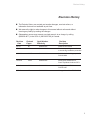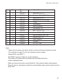
1
Installation Manual with Service Replacement Parts Rotary-type Conveyor Glasswasher Models: DFM7 Clockwise Rotation DFM7-1 Clockwise Rotation DFM7-2 Counter-Clockwise Rotation DFM7 (Clockwise Rotation) Glasswasher serial no. Issue Date: 5.26.10 Manual P/N 0512651 rev. E For machines beginning with S/N G080410261 P.O. Box 4183 Winston-Salem, NC 27115 336/661-1992 Fax: 336/661-1660 Toll-free: 800.858.4477 2674 N. Service Road, Jordan Station Ontario, Canada L0R 1S0 905/562-4195 Fax: 905/562-4618 Toll-free: 800.263.5798 Printed in the USA For future reference, record your glasswasher information in the box below. Model Number__________________________ Serial Number_______________________ Voltage________________Hertz_____________ Phase__________________ Service Agent __________________________________ Tel:______________________ Parts Distributor _________________________________ Tel:______________________ National Service Department In Canada: Toll-free: 800/ 263-5798 Tel: 905/ 562-4195 Fax: 905/ 562-4618 email: [email protected] In the USA: Toll-free: 800/ 858-4477 Tel: 336/ 661-1992 Fax: 336/ 661-1660 email: [email protected] ATTENTION: The glasswasher model no., serial no., voltage, Hz and phase are needed to identify your machine and to answer questions. Please have this information on-hand if you call for service assistance. The USGBC and the CaGBC Member Logos are trademarks owned by the U.S. Green Building Council and The Canadian Green Building Council, respectively, and are used by permission. The logos signify only that Moyer Diebel is a USGBC member and a CaGBC member; USGBC and CaGBC do not review, certify nor endorse the products or services offered by its members. COPYRIGHT © 2010 All rights reserved Printed in the USA ATTENTION: Complete the back of the POSTAGE PAID WARRANTY CARD below, then cut along the dashed lines and mail immediately to make sure that your machine warranty is validated. USE CANADIAN WARRANTY CARD IN CANADA AND USA WARRANTY CARD IN THE UNITED STATES. NO POSTAGE NECESSARY IF MAILED IN THE UNITED STATES BUSINESS REPLY MAIL FIRST-CLASS MAIL PERMIT NO. 2101 WINSTON-SALEM, NC POSTAGE WILL BE PAID BY ADDRESSEE MOYER DIEBEL PO BOX 4183 WINSTON-SALEM, NC 27119-0981 WARRANTY REGISTRATION CARD Serial # Model Date of Installation: Company Name: Address: Telephone #: ( ) --- (Street) State or Province Zip Code Contact: Installation Company: Address: Telephone #: Contact: This Card Must Be Returned to Validate Machine Warranty: IMPORTANT IMPORTANT WARRANTY REGISTRATION CARD Serial # Model Date of Installation: Company Name: Address: Telephone #: ( ) --- (Street) State or Province Zip Code Contact: Installation Company: Address: Telephone #: Contact: This Card Must Be Returned to Validate Machine Warranty: IMPORTANT IMPORTANT Revison History Revision History The Revision History can contain part number changes, new instructions, or information that were not available at print time. We reserve the right to make changes to this manual without notice and without incurring any liability by making the changes. Glasswasher owners may request a revised manual, at no charge, by calling (800.858.4477) in the USA or (800.263.5798) in Canada. Revision Date 5.6.08 Revised Pages All Serial Number Revision Effectivity Description G080410261 Released first edition 7.7.08 1-5 G080410261 Revised unpacking instructions to include leg installation procedure 10.20.08 36-37 G080410261 Added chemical tubing to parts list P/N 0502666 10.20.08 38-39 G080410261 Added parts breakdown for Drain Tray/Waste Collector DF71 2.15.10 22-23 G080410261 Changed Item 11 P/N to P/N 0501437 5.27.10 35 Changed Item 26 to P/N 201669 G080410261 i Dear Owner: Thank you for choosing our glasswasher. We appreciate your business. This manual covers: Model DFM7 Rotary-Type Glasswasher, Clockwise Conveyor Rotation (access door front) Model DFM7-1 Rotary-Type Glasswasher, Clockwise Conveyor Rotation (access door right) Model DFM7-2 Rotary-Type Glasswasher, Clockwise Conveyor Rotation (access door left) The installation, and initial start-up of your glasswasher must be performed by qualified electricians, plumbers, and authorized service technicians who are trained in commercial glasswashers. ii DFM7 - Table of Contents Table of Contents Revision Record.......................................................................................................... i Limited Warranty......................................................................................................... iv DFM7 Rotary-type Conveyor Glasswasher Installation ------------------------------------------------------------------------------------ 1 Unpacking-------------------------------------------------------------------------------------- 1 Utility Connections--------------------------------------------------------------------------- 3 Chemicals-------------------------------------------------------------------------------------- 4 Operation-------------------------------------------------------------------------------------- 6 Cleaning - ------------------------------------------------------------------------------------ 9 Troubleshooting------------------------------------------------------------------------------ 10 Service Replacement Parts--------------------------------------------------------------- 15 Electric Schematic--------------------------------------------------------------------------- 40 iii DFM7 - Limited Warranty LIMITED WARRANTY Moyer Diebel, (herein referred to as "The Company"), P.O. Box 4149, Winston-Salem, North Carolina 27115, and Champion-Moyer Diebel P.O. Box 301, 2674 N. Service Road, Jordan Station, Canada, L0R 1S0, warrants machines, and parts, as set out below. Warranty of Machines: "The Company" warrants all new machines of its manufacture bearing the name "The Company" and installed within the United States and Canada to be free from defects in material and workman ship for a period of one (1) year after the date of installation or fifteen (15) months after the date of shipment by "The Company", whichever occurs first. [See below for special provisions relating to glasswashers.] The warranty registration card must be returned to "The Company" within ten (10) days after installation. If warranty card is not returned to "The Company" within such period, the warranty will expire after one year from the date of shipment. "The Company" will not assume any responsibility for extra costs for installation in any area where there are jurisdictional problems with local trades or unions. If a defect in workmanship or material is found to exist within the warranty period, "The Company", at its election, will either repair or replace the defective machine or accept return of the machine for full credit; provided; however, as to glasswashers, "The Company's" obligation with respect to labor associated with any repairs shall end (a) 120 days after shipment, or (b) 90 days after installation, whichever occurs first. In the event that "The Company" elects to repair, the labor and work to be performed in connection with the warranty shall be done during regular working hours by a "The Company" authorized service technician. Defective parts become the property of The Company. Use of replacement parts not authorized by "The Company" will relieve "The Company" of all further liability in connection with its warranty. In no event will "The Company's" warranty obligation exceed "The Company's" charge for the machine. The following are not covered by "The Company's" warranty: a. b. c. d. e. f. g. h. i. j. Lighting of gas pilots or burners. Cleaning of gas lines. Replacement of fuses or resetting of overload breakers. Adjustment of thermostats. Adjustment of clutches. Opening or closing of utility supply valves or switching of electrical supply current. Cleaning of valves, strainers, screens, nozzles, or spray pipes. Performance of regular maintenance and cleaning as outlined in operator’s . Damages resulting from water conditions, accidents, alterations, improper use, abuse, tampering, improper installation, or failure to follow maintenance and operation procedures. Wear on Pulper cutter blocks, pulse vanes, and auger brush. Examples of the defects not covered by warranty include, but are not limited to: (1) Damage to the exterior or interior finish as a result of the above, (2) Use with utility service other than that designated on the rating plate, (3) Improper connection to utility service, (4) Inadequate or excessive water pressure, (5) Corrosion from chemicals dispensed in excess of recommended concentrations, (6) Failure of electrical components due to connection of chemical dispensing equipment installed by others, (7) Leaks or damage resulting from such leaks caused by the installer, including those at machine table connections or by connection of chemical dispensing equipment installed by others, (8) Failure to comply with local building codes, (9) Damage caused by labor dispute. Warranty of Parts: "The Company" warrants all new machine parts produced or authorized by "The Company" to be free from defects in material and workmanship for a period of 90 days from date of invoice. If any defect in material and workmanship is found to exist within the warranty period "The Company" will replace the defective part without charge. DISCLAIMER OF WARRANTIES AND LIMITATIONS OF LIABILITY. MOYER DIEBEL'S WARRANTY IS ONLY TO THE EXTENT REFLECTED ABOVE. MOYER DIEBEL MAKES NO OTHER WARRANTIES, EXPRESS OR IMPLIED, INCLUDING, BUT NOT LIMITED, TO ANY WARRANTY OF MERCHANTABILITY, OR FITNESS OF PURPOSE. MOYER DIEBEL SHALL NOT BE LIABLE FOR INCIDENTAL OR CONSEQUENTIAL DAMAGES. THE REMEDIES SET OUT ABOVE ARE THE EXCLUSIVE REMEDIES FOR ANY DEFECTS FOUND TO EXIST IN MOYER DIEBEL GLASSWASHERS AND MOYER DIEBEL PARTS, AND ALL OTHER REMEDIES ARE EXCLUDED, INCLUDING ANY LIABILITY FOR INCIDENTALS OR CONSEQUENTIAL DAMAGES. Moyer Diebel does not authorize any other person, including persons who deal in its glasswashing machines to change this warranty or create any other obligation in connection with its glasswashing Machines. iv Installation Installation Unpacking 1. Move the glasswasher to its permanent location. 2. Open the door and remove the box marked "LEGS". The box contains (4) 6" [152cm] screw-in legs. These legs are threaded tightly into the base of the machine. 3. Remove (2) 1/2-13 x 2" bolts holding the glasswasher to the pallet. 4. Lift the front door off the bottom hinges and set carefully aside. 5. The illustrations below show one method to install the legs without lifting the glasswasher completely off the pallet. CAUTION! The glasswasher water inlet plumbing and the drain piping extend below the pallet. Use extreme care when moving the glasswasher to prevent damage to the glasswasher plumbing. Boxed Legs Drain Water Connections Remove the (2) pallet bolts holding the glasswasher to the pallet. Pallet Glasswasher plumbing connections extend below the pallet. 1 Installation Installation (continued) Unpacking (continued) 6. Use 2 people to move the machine in order to install the legs. 7. Have 1 person behind the glasswasher tilt it back as the person in front twists the machine to the right. This makes the front left leg mounting hole accessible. 8. Screw 1 of the legs tightly into place. Repeat this process for the remaining legs. 9. Lift the glasswasher off the pallet, and re-install the front door.. 10. Level the glasswasher front-to-back and side-to-side by adjusting the leg bullet feet in or out. 11. Compare the site utilities with the data plate specifications. If they agree, then proceed with the installation according to the diagrams on the next page. 12. Remove the packing material in the glasswasher and discard, then remove any protective film on the machine. Twist the glasswasher to the right, then to the left. Tilt the machine back to clear plumbing connections. TILT Twist the machine to the right until the front right leg mounting hole is accessible. Thread (1) leg in each corner of the machine base 1" 6"-7½" 1½" Make sure to install the legs tightly. 2 Level front-to-back and side-to-side Installation Utility Connections (continued) ATTENTION 4 All utility connections must be performed by qualified people that will follow electric, plumbing, and sanitary codes and regulations. 6 ft. (1.5M) 25" [635] Plan View 1 140-160°F/60-71°C ½" IPS Flow pressure 25-95 PSI [173-655 kPa]. Install water shut-off valves and check-valves in the water inlet supply lines and as close to the machine as possible 2 2 Hot Water Connection: 3 6¼" [156] 1 8¾" [222] 2½" [64] Cold Water Connection: 75°F/24°C ½" IPS Flow pressure 25-95 PSI [173-655 kPa]. 39" [991] Front View 2 1 3 4 7¼" [181] 6¼" [156] Install water shut-off valves and check-valves in the water inlet supply lines and as close to the machine as possible 3 27" [686] 5½" [140] 4¾" [121] Drain Connection: Gravity 1½" Tailpiece (slip-fit) Maximum drain flow 3 US gallons/min [11L/min] 17¾" [451] Electric Connection: Side View 208-230VAC/50-60HZ/1PH Min/Max 15A 6 ft. /1.5 m flexible cord and plug supplied NEMA 6-15P electric outlet 39" [991] 2 1 3 7¼" [184] National Service Dept. USA: 1-800 858-4477 Canada: 1-800 263-5798 8¾" [222] 13½" [343] 3 Installation Installation (continued) Chemicals Glassware cleaning chemicals 1. A qualified chemical supplier should supply liquid detergent, sanitizer and rinse-aid for the glasswasher. The glasswasher manufacturer does not sell glassware washing chemicals. 2. A chemical's formulation and strength vary depending on the chemical supplier; therefore, the specifications given below are approximations only. 3. The glasswasher has 3 built-in chemical dispensing pumps for Detergent - Use a commercial grade non-chlorinated detergent specifically made for glasswashers. The recommended concentration of detergent should be .35% Sanitizer - 2 types of sanitizer may be used. Rinse-aid (5.25%) Sodium hypochlorite (chlorine bleach) to provide a minimum concentration of 50 ppm in the final rinse. The 50 ppm concentration must be checked using test strips to make sure the proper concentration is maintained. Iodophor (Iodine formulated with a rinse agent), to provide a minimum concentration of 12.5ppm in the final rinse. The 12.5 ppm concentration must be checked using test strips to make sure the proper concentration is maintained. Consult your chemical supplier for the proper type of rinse-aid to use in the glasswasher. Installing chemical supply containers and chemical pick-up tubes 1. There is enough space inside the lower compartment to hold 3 one gallon containers for detergent, sanitizer, and rinse-aid. The contents of each container must be marked clearly. 2. The glasswasher comes equipped with 3 gray tubes, called stiffener tubes, and tubing for each chemical pump. The tubing inserted in the chemical container has a strainer. 3. The outlet tubes from the supply containers to the chemical pumps are marked with color-coded labels, they are: 4 RED - CLEAR - BLUE - Detergent Sanitizer Rinse-aid (DET) (SAN) (R/A) 4. Pull the stiffener tubes and chemical tubing forward and out of the compartment. Make sure the tubing is not tangled or kinked. 5. Insert the stiffener tube and pick-up tubing into its container and stow the supply containers in the lower compartment as shown to the right. DET RED SAN CLEAR DETERGENT DET R/A BLUE SANITIZER SAN RINSE R/A Installation Priming the Chemical Injectors and Approximate Chemical Settings Each chemical injector can be adjusted using its prime button and concentration adjusting screw. These controls are located on the right side of the control box located in the lower compartment of the glasswasher. The white injector rotors are visible through the control box window. Push to prime Rotor Rinse-aid Sanitizer Detergent + Turn CW to increase(+) R/A SAN DET CCW to decrease (-) Chemical Injector Prime and Concentration Controls ALL OF THE CHEMICAL SETTINGS BELOW ARE APPROXIMATIONS. CONSULT A QUALIFIED CHEMICAL REPRESENTATIVE TRAINED IN THE USE OF THE TEST EQUIPMENT REQUIRED FOR TAKING SAMPLES AND PERFORMING ADJUSTMENTS. 1. Priming the Pumps: Make sure the proper chemical pick-up tube is in its supply container, then push and hold the prime button until the detergent, sanitizer and rinse-aid feed tubes are full of chemical. Release the Prime button. 2. Approximate Chemical Settings: The approximate chemical volume dispensed by the chemical injectors can be determined by counting the number of revolutions of the injector rotor. Detergent - 1 revolution in 1-second of the detergent pump rotor ~ 0.35% concentration. Sanitizer - 1 revolution in 5-seconds ~ 12.5 ppm of Iodophor or 50 ppm of chlorine. Rinse-aid - 1 revolution in 8-seconds ~ the median volume recommended. Turn the Injector Concentration screws clockwise to increase or counter-clockwise to decrease the volume of dispensed chemical. 3. The detergent chemical setting must be performed when the hot-water fill solenoid valve is open. The hot-water valve is open when the power switch is in the ON position during initial fill and when the detergent tank float assembly calls for hot water The sanitizer and the rinse-aid setting can be performed whenever the cold-water fill solenoid valve is open. The cold-water fill valve is open whenever the glasswasher power switch is ON and the conveyor is turning. A separate rinse-aid is not needed when Iodophor is used as a sanitizer. Turn the Injector Concentration Screw fully counter-clockwise until the rinse-aid injector rotor stops turning. 5 Operation Flow Diagram The diagram below shows the major components of the DFM7 glasswasher and the flow of water and chemicals during normal operation. 6 Operation Quick Operation Guide The glass washing machine is designed to automatically wash a wide variety of glassware. 8 The glass washer consists of a wash section and rinse section. Glasses rotate on a conveyor through each section. A wash tank in the lower compartment holds heated wash water. The water level in the wash tank is maintained by a float and cam-operated switch. The wash tank water temperature is controlled by a heater and a 1 thermostat. The rinse water is supplied from the cold water supply. Chemicals are automatically dispensed by built-in chemical pumps 2 1 3 4 5 7 MIX Plug machine power cord into a 208-230VAC/60/1,15 A wall receptacle. Turn main power and water service ON. 2 3 Remove lower wash tank scrap screen. 5 Make sure a glass is against the conveyor stop switch, Push the rocker switch UP to the ON Prime position until the wash tank is full of water. Prime Then, push and hold each chemical Prime button until chemical supply tubes are full. On Off Flush Prime R/A Sani Det. Install the drain/ overflow tube into the drain located at the front of the wash tank bottom. Re-install the scrap screen removed in Step 2. 6 The incoming cold water supply temperature must MIX be a minimum temperature of 75°F/24°C. Adjust the temperature of the incoming cold water temperature by opening or closing the mixing valve located between the hot water and the cold water solenoid valves. 7 4 6 White Label Sanitizer Red Label Detergent Blue Label Pull the chemical pick-up tubes out Rinse-aid of the machine Colored labels I.D. each tube Place tube into its supply container. 7 Check the cold water temperature gauge and the cold water pressure gauge as you adjust the mixing valve. The minimum temperature should be 75°F/24°C. The pressure gauge should read a flowing pressure of 4-6 psi/24-36 kPa. Pressure Check the wash tank temperature gauge Temperature for 140°F/60°CWash Tank Heat 160°F/71°C. 8 Place glassware on the conveyor. The conveyor stops automatically when when the clean glassware operates the conveyor stop switch. 7 Operation Operation (continued) Assembling the Glasswasher 1. 2. Make sure the power switch is in the OFF position. Install the wash arms and rinse spray arms. The spray arms have locating notches in the end of each arm. Push the spray arm straight into the hub. Do not twist. 3. 4. Install the conveyor assembly as follows: Insert the conveyor into the wash chamber keeping the rear raised. Pull the conveyor forward until it meshes with the drive gear located at the front of the wash chamber. Continue to pull the conveyor forward as you lower it on the pivot. Install the stainless steel cylinder in the center of the conveyor. 5. Install the conveyor shut-off assembly (plexiglass divider). 6. 7. 8. 9. Install the right and left hand tray. Install the curtain assembly. Install the upper and lower scrap screens. Install the standpipe in the detergent tank. Twist slightly to make sure it seats securely in the drain. Install the drain tray/waste collector (if equipped). Make sure the drain fitting is secure. Make sure the chemical supply containers are full. Close the door. 9. 10. 11. Filling the Wash Tank 1. 2. Ensure that the overflow/drain tube is in place in the detergent tank. Flip power on-off/flush switch to the “ON” position. The water will fill until the proper water level is reached. 3. The water temperature is controlled by a tank heater and an adjustable thermostat. The thermostat should be set for a minimum of 140°F/60°C. Operating Instructions 1. Ensure that chemical supply containers are full. 2. Detergent is fed into the detergent in controlled amounts detergent dispensing pump. Use detergent at a strength recommended by your chemical supplier. 3. Open the front door and flip the on/off/flush switch to the “ON” position. The detergent tank will fill automatically. 4. Load glasses on the conveyor. The conveyor will stop when the glasses contact the conveyor shut-off switch. 8 Cleaning Cleaning Instructions The cleaning instructions are attached to the inside of glasswasher front door. Daily Cleaning or after 8 hours of Operation: 1. Make sure that any glasses on the conveyor are clean, then remove them from the conveyor. 2. Push the On/Off/Flush switch on the right-hand side of the glasswasher control box to the Off position. 3. Remove the splash curtain from the curtain hooks located at each end of the splash curtain rod. 3. Remove the (2) stainless steel conveyor guards located at each corner of the glasswasher and the plexiglass stop assembly. 4. Remove the cylindrical stainless steel conveyor guard located in the center of the glasswasher. 5. Remove the conveyor by lifting the rear of the conveyor while pulling it forward to disengage the conveyor drive gear located at the right front corner of the wash chamber. 6. Take these parts to a sink, and wash in hot soapy water using a soft brush and cloth, then rinse with fresh water and set aside to air dry. DO NOT CLEAN WITH HARSH DETERGENTS OR ABRASIVE SCOURING PADS. DO NOT STRIKE THE CONVEYOR ON THE FLOOR OR ANY HARD SURFACE. 7. Clean the wash chamber interior with hot soapy water, then rinse with fresh water. Wipe the interior with a soft cloth. Allow the wash chamber to air dry overnight. 8. Remove the upper scrap screen, remove large debris in a trash can, take screen to a sink and flush screen with fresh water. DO NOT STRIKE SCREENS ON HARD SURFACES. 9. Remove the lower scrap screen, remove large debris in a trash can, take screen to a sink and flush clean with fresh water. 10. Remove the stainless steel wash tank cover; clean with hot soapy water at a the wash sink. Wipe clean and dry. 11. Remove the detergent wash tank drain/overflow to drain the tank, then flush the tank with fresh water and wipe with a clean cloth. 12. Reassemble the glasswasher in reverse order for continued operation, or leave disassembled overnight to aid drying. DO NOT LEAVE WATER IN THE GLASSWASHER OVERNIGHT Weekly Cleaning, after 7 days or 56 hours of Operation. 1. Complete 1-11 in the Daily Cleaning above. 2. Remove chemical supply containers if they are stowed inside the glasswasher, wipe any chemical spills with a damp cloth. Detergent and sanitizer (Chlorine) are corrosive on metal and must be removed as much as possible. 3. Check the inlet chute on the right-side of the detergent tank and flush with fresh warm water to clean any chemical residue. 4. Check chemical supply lines. If a line(s) are restricted, remove the pick-up tube(s) from the container(s), then insert each pick-up tube in separate container(s) filled with fresh warm water. 5. PUSH and HOLD the PRIME BUTTON labeled for the matching chemical tube until the water moves freely through the supply tubing. Repeat for each chemical making sure that the warm water is fresh and free of any other chemical. 6. Return the the pick-up tube(s) to the chemical container matching the label on the supply tube(s), then PUSH and HOLD the PRIME BUTTON for the matching chemical(s) until the chemical moves freely through the supply tube(s). 7. Inspect the chemical dispensing pumps visible behind the plexiglass window located on the front of the control box. PUSH and HOLD a each PRIME BUTTON. One white wheel behind the window for each PRIME BUTTON pushed and held. 8. Find the spray tube assemblies, (3 spray tubes each) located in the wash chamber. There are (2) assemblies in the top and (2) assemblies in the bottom. Pull (1) assembly at a time. Check the black O-ring on the spray tube hub for damage, replace if missing. 9. Insert and twist the small brass drill bit (reamer) in the each spray tube hole to clean. Insert and twist the large drill on the wood handle. Push the large reamer down the length of the spray tubes. Insert and twist the long brush in each spray tube to remove loose debris. Flush the spray tube assembly, then reinstall in the glasswasher. Repeat for each spray tube assembly. 10. Reassemble the glasswasher in reverse order for continued operation, or leave disassembled overnight to aid drying. 9 Troubleshooting The following troubleshooting guide can help identify a problem and provide a solution. Inspect your glasswasher before you contact an authorized service representative. Problem Glasswasher will not turn ON. Conveyor will not rotate. Conveyor will not stop rotating. Conveyor rotates in wrong direction. Upper scrap screen is hard to remove. Front door will not close remain closed. Glasswasher not level or rocks back and forth. 10 Cause(s) Solution(s) Main breaker/fuse box OFF Turn breaker/fuse box ON. Disconnect fuse blown/breaker tripped. Glasswasher ON/OFF switch OFF. Power cord unplugged. Clean glass(es) touching the conveyor shut-off switch. Conveyor center hub out of position. Conveyor support(s) out of position and/or broken. Drive gear out of position. Turn breaker/fuse box ON. Replace fuse/Reset Breaker. Gear teeth on conveyor worn or broken. Replace the conveyor. Gear teeth on drive gear worn or broken. Replace drive gear. Object jamming the conveyor. Remove object. Conveyor drive motor defective. Authorized service agent may replace conveyor drive motor. Conveyor stop switch needs adjustment or switch is defective. Authorized Service Agent may adjust or replace switch. The drive motor is turning the conveyor backward. Large debris, such as broken glass is on screen. Flip ON/OFF switch ON. Plug-in power cord. Remove clean glasses from the rinse-side of the glasswasher. Reposition the conveyor. Reposition or replace support(s). Reposition drive gear. Authorized Service Agent may remove drive motor rotate motor stator 180° and re-install. Scrap screen bent and/or broken. Door magnet broken or missing. Door bent or broken. Floor is not level. Leg(s) are not screwed firmly into machine base. Remove conveyor and lower spray arm(s). Remove debris. Authorized Service Agent may repair or replace damaged screen. Replace door magnet. Straighten or replace door. Use bubble level and turn bullet feet in/out to adjust machine level. Tighten leg(s) or replace. Troubleshooting Problem Water sprays out the front of the glasswasher. Poor washing results. Cause(s) Splash curtain is missing, positioned incorrectly or damaged. Re-install the splash curtain or replace the splash curtain. Spray arm(s) are damaged or missing. Replace spray arm(s). Glass(es) interferes with splash curtain. Reload glass(es). Clogged spray arm(s) makes water come out in wrong direction. Clean the spray arm(s). Water volume from wash and/or rinse spray arm(s) low. Clean spray arm(s). Water level in detergent tank low. Re-install drain/overflow tube in wash tank. Service Agent must adjust water level switch until water level is below top of overflow. Chemical supply container(s) fill with water. Solution(s) Water level float ball stuck or filling with water. Water level switch defective. Detergent and/or rinse-aid supply low. Authorized service agent may replace switch. Wash pump and/or water valve(s) and/or line strainers clogged or defective. Authorized service agent may replace wash pump and/or solenoid valve(s). Clean line strainers. Detergent tank temperature low. Raise incoming water temperature or adjust thermostat for 140°F/60°C in detergent tank. Chemical injectors out of adjustment. Peristaltic tube(s) are stretched or worn on the glasswasher chemical pump(s). Contact chemical supplier to calibrate settings. Flow control washer in cold water solenoid valve is defective. Clean float ball, replace if filling with water. Refill chemical supplies. Inspect and replace tube(s). Contact service agent to repair solenoid valve. 11 Troubleshooting Problem Water temperature below 145°F/66°C in detergent tank. Cause(s) Detergent tank thermostat temperature setting low. Thermostat is defective. Detergent tank heater is defective. Water leaking under glasswasher. Incoming water temperature is below 140°F/60°C. Increase thermostat setting to 145°F/66°C Authorized service agent may replace thermostat. Authorized service agent may replace detergent tank heater. Raise incoming water temperature to 140°F/60°C. Pump water seal defective. Authorized service agent may replace pump seal. Glasswasher drain line is clogged. Clean drain line. Upper wash compartment drain screen is clogged. Clean drain screen. Detergent tank drain screen is clogged. Clean detergent tank drain screen. Building drain line is clogged. Clean building drain line. Condensation is forming on the underside of wash compartment. Open rinse water mixing valve until temperature of water 70°F/21°C Vacuum breaker at rear of glasswasher leaking. 12 Solution(s) Replace vacuum breaker. Troubleshooting Problem Water flows into glasswasher when ON/OFF switch is in the OFF position. Cause(s) Flowing water supply line pressure measured at the glasswasher exceeds 95 psi [655 kPa]. Defective solenoid valve(s). Chemical(s) are not flowing into the glasswasher. Defective AUTO-FILL switch. Rinse water pressure too high Chemical container(s) are empty. Chemical supply line(s) are clogged. Chemical supply and/or pump tube(s) are broken. No power to chemical dispensing pump(s). Dispensing pump is defective. Chemical pumps out of adjustment Solution(s) Incoming water pressure must be 5 PSI/35 kPa on pressure gauge located on right-side of glasswasher lower compartment Authorized service agent may rebuild or replace the solenoid valve(s). Service agent replace the switch. Reduce flowing water pressure measured at the glasswasher below 95 psi [655 kPa]. Refill the container(s). Remove the supply line(s) from the chemical containers and flush with warm water. Replace supply line(s) and/or pump tube(s). Authorized service agent may replace chemical dispensing pump. Authorized service agent must inspect and repair Chemical supplier must adjust chemical pumps. 13 Blank Page This Page Intentionally Left Blank 14 Service Replacement Parts Service Replacement Parts Illustration List______________________________________ Page Base Assembly....................................................................................................... 16 Conveyor, Guides, Curtains................................................................................... 18 Wash Hubs, Spray Arms........................................................................................ 20 Conveyor Stop Switch............................................................................................ 22 Drive Motor Assembly............................................................................................ 24 Vacuum Breaker Assembly..................................................................................... 26 Wash Pump and Piping.......................................................................................... 28 Inlet Plumbing......................................................................................................... 30 Sanitizer Plumbling................................................................................................. 32 Detergent Tank Assembly....................................................................................... 34 Control Box Assembly............................................................................................ 36 Options and Accessories........................................................................................ 38 15 Base Assembly 8 8 12 8 15 8 13 14 1 2 10 3 4 11 18 17 10 19 5 8 9 5 20 16 8 8 5 7 6 16 Base Assembly Item No. Part No. Description Qty. 1 1 112519 Cap Plug, 1" 2 1 0501885 Magnetic Door Catch 3 1 0712644 Wash Tank Scrap Screen 4 1 0312608 Wash Tank Scrap Screen Handle 5 4 0501873 Leg 6" 6 1 0712642 Door Assy. 7 1 111561 Door Handle 8 10 100007 Screw, 1/4-20 X1/2" truss head 9 1 0712647 Door Bracket Assy. 10 2 0501412 Screw, 10-32 x 3/8" 11 1 0312597 Curved facia cap bracke t 12 1 0312601 Rear Panel 13 2 106026 Flat Washer 1/4" 14 2 107697 1/4-20 Nylon Lock nut 15 1 0512696 Curved facia cap 16 1 0507471 Label, (CLEAN SCREENS DAILY) 17 1 0503301 Label, (WARNING...) 18 1 0505112 Data Plate Label 19 1 0512659 Cleaning Instructions Label 20 1 0512658 Electrical Schematic Label 17 Conveyor, Guides, Curtains 1 2 5 3 4 3 6 7 18 Conveyor, Guides, Curtains Item No. Qty. Part No. Description 1 1 0312603 Conveyor Hub 2 4 0312695 Conveyor Guide Block 3 2 0312604 Conveyor Tray 4 1 0506886 Drive Gear 5 1 0506885 Conveyor 6 1 0312610 Curtain Rod (3/8"D x 24"L) 7 1 0512549 Curtain 19 Wash Hubs, Spray Arms 2 1 upper wash spray arm notch in center upper rinse spray arm notch on right 12 11 10 13 1 3 4 6 3 7 2 1 DFM7 and DFM7-1 Clockwise conveyor rotation Shown 8 3 3 5 9 1 8 2 lower wash spray arm notch in center 20 2 lower rinse spray arm notch on left Wash Hubs, Spray Arms Item No. Qty. Part No. Description *1 2 0501613 Wash Arm DF, DF-1 ---- 2 0501692 Wash Arm DF-2 (CCW Only) *2 2 0501738 Rinse Arm DF, DF-1 --- 2 0501740 Rinse Arm DF-2 (CCW only) 3 4 0501608 O-ring 4 1 0501610 Top Manifold 5 1 0301622 Bottom Manifold 6 1 106026 Flat Washer, 1/4" 7 2 0501422 Bolt, 1/4-20 x 1-1/2" 8 2 0501412 Screw, 10-32 x 3/8" 9 2 0500813 Bottom Manifold Inlet Tube 10 AR 0502663 Braided Hose, 3/8" 11 4 0303679 Gear Clamp #6 12 2 0509478 Grommet 13 1 0300908 3/8" SST Tube Note: * Wash and rinse spray arms have notches to make sure they are installed correctly. The illustration on page 20 is for the clockwise conveyor rotation Models DFM7, and DFM7-1. The DFM7-2 conveyor rotation is counter-clockwise. The location of the wash and rinse spray arms are different than the models mentioned above. Make sure that you know the correct Model No. of the machine before ordering parts. Read the item no. descriptions carefully to avoid mistakes when ordering wash and rinse spray arms. 21 Conveyor Stop Switch 3 1 2 4 5 6 7 10 11 9 8 22 Conveyor Stop Switch Item No. Qty. Part No. Description 1 1 0512556 Divider Plate 2 2 0501412 Screw 10-32 x 3/8" 3 1 0712648 Shut-off Arm Assy. 4 1 0512555 Conveyor Shut-off Shaft 5 1 0512559 Spring 6 1 0512557 Conveyor Shut-off Cam 7 1 0510854 Dog-point Screw 1/4-20 x 1/2" 8 1 0510493 Carriage Bolt 10-24 x 1/2" 9 1 0312605 Switch nut plate 10 1 0501379 Switch 15A 11 2 0501437 Screw 4-40 x 1/2" ____ 1 0712735 Shut-off Assembly (Includes Items 1, 2, 3 23 Drive Motor Assembly 1 2 3 8 5 7 4 5 6 24 Drive Motor Assembly Item No. Qty. Part No. Description 1 1 0506886 Drive Gear 2 1 0507264 Water Slinger 3 1 0501923 Extension Spring 4 1 0512713 Snap Bushing 5 4 0501412 Screw 10-32 x 3/8" 6 1 0307617 Drive Motor Housing Cover 7 1 0512532 Drive Motor 8 1 0712712 Drive Motor Housing 25 Vacuum Breaker Assembly 4 5 3 2 6 2 1 1 7 8 9 26 Vacuum Breaker Assembly Item No. Qty. Part No. Description 1 A/R 0502665 1/2" I.D. Braided Hose 2 2 0503679 7/16" Gear Clamp 3 1 0502653 3/8" MPT x 1/2" MPT Hose Barb 4 1 100500 1/2" Vacuum Breaker 5 1 0508366 Vacuum Breaker Repair Kit 6 1 0502651 1/2" MPT x 1/2" Hose barb 7 1 0312684 Plumbing Support 8 2 106026 Washer, Flat 1/4" 9 2 107967 Nylon Locknut 1/4-20 27 7 7 6 7 11 10 10 12 9 8 3 1 5 2 4 Wash Pump and Piping 28 Wash Pump and Piping Item No. Qty. Part No. Description 1 1 0512679 Motor Capacitor 6.3uF, 370VAC * 2 1 0512531 Wash Pump/Motor Assy. Complete 230V/50-60Hz/1Ph 3 1 0512678 Pump Kit (Items 4 & 5 are included in the kit) 4 1 0512677 Wash Pump Shaft Seal 5 1 0512680 Wash Pump Impeller 6 6" 0507320 Hose 1" ID x 1-1/4" OD 7 AR 0502563 Hose Clamp #6 8 6" 0502668 Braided Hose 1" ID 9 1 0501632 Pump Hose Connector 10 AR 0503679 Hose Clamp #16 11 AR 0502665 Braided Hose 1/2" 12 AR 0502663 Braided Hose 3/8" * Note: The pump motor is not available as a separate service replacement part. 29 Inlet Plumbing To Vacuum Breaker 6 8 7 1 To Detergent Tank 8 6 7 1 9 4 2 3 2 Cold Water Valve 5 2 3 13 Water solenoid detail 14 Hot Water Valve 15 20 21 12 19 18 16 1 11 10 17 22 23 30 Inlet Plumbing Item No. 1 2 3 4 5 6 7 8 9 10 11 12 13 14 15 16 17 18 19 20 21 22 23 Part No. 0502783 0502802 0503801 0507324 0502768 0502653 0503679 0502665 0509659 0504822 0306208 0307373 0501404 0501493 0501533 0505229 0502811 0502810 0502807 0502804 0502803 0501406 0502806 Description Solenoid Valve, 230VAC/60 HZ 3/8” MPT Tee 3/8” Fem x 1/2” Adapter 3/8” Check Valve Mixing Valve 3/8” x 1/2’ 90º Hose Barb 7/16” Gear Clamp 1/2” I.D. Braided Hose Brass Cap Screw 8-32 x 1/2” Cable Clamp Cover Cable Clamp Assy. Screw 10-32 x 3/8” Brass Lock Washer #10 Nut 10-32 Brass Solenoid Guide Diaphragm Kit Flow Washer (2.6 gpm) Brass Washer Brass Washer Screen Screw 8-32 x 1/2” Coil, Solenoid Valve, 230VAC/60 Qty. 2 3 1 1 1 2 2 A/R 1 2 2 2 2 2 2 1 A/R 1 1 1 1 2 1 31 32 14 1 2 13 4 2 3 15 2 7 6 1 2 1 5 2 8 12 11 10 10 9 Sanitizer Plumbing Sanitizer Plumbing Item No. Qty. Part No. Description 1 AR 0502665 1/2" I.D. Braided Hose 2 5 0503679 7/16" Gear Clamp 3 AR 0502663 3/8" I.D. Braided Hose 4 1 0502652 1/2" x 1/2" x 3/8" Tee 5 1 0503669 Injector Barb Fitting 6 2 0501519 Cable Tie 4" 7 AR 0502666 Chemical Tubing 1/8" IDx1/4"OD 8 1 0502653 3/8" MPT x 1/2" 90° Hose Barb 9 1 0503668 Thermometer 10 2 0502577 3/8 x 1/4" Reducer Bushing 11 1 0502583 3/8" FPT Cross Connector 12 1 0507100 0-30 PSI Pressure Gauge 13 1 0300918 Plumbing Clamp 14 2 0512185 Bolt, 1/4-20 x 3/8" 15 2 0502645 1/8" hose barb fitting 33 Detergent tank Assembly 1 2 3 34 CLE AN 4 5 SCR EEN S DA ILY 6 9 8 10 33 7 11 23 12 25 20 21 13 26 14 24 28 15 29 32 27 19 16 18 17 30 31 To control box 23 34 22 Detergent tank Assembly Item No. Qty. Part No. Description 1 1 0312592 Steam Cover 2 1 0312591 Detergent Tank Cover 3 1 0712641 Detergent Tank Screen 4 1 0501395 Set Screw 1/4-20 5 1 0312682 Float Cam 6 2 0501397 Set Screw 6-40 7 2 0703673 Cam Bushing (set screw included) 8 1 0512554 Float Rod 9 1 0503670 Float Ball 10 1 0712640 Detergent Tank 11 1 0307427 Water Inlet Tube 12 1 0503679 Hose Clamp #6 13 A/R 0502665 Braided Hose 1/2" 14 6" 0502668 PVC Hose 1" ID x 1-3/8" OD 15 1 0502563 Gear Clamp 1" 16 1 108051 Elbow Flange 17 4 0507431 Bolt M6 x 25mm (metric) 18 1 107886 Inlet Chute Gasket 19 4 107435 Nut, M6 (metric) 20 1 0512535 Molded Drain Seat 21 1 0512536 Drain Gasket 22 1 0512534 Modeled Drain Tee 23 2 0502571 Hose Clamp 1-1/2" 24 1 0512533 Molded Drain Hose 25 1 0512550 Float Rod Bushing 26 1 201669 1/4" NPS NP Brass Nut 27 1 0501600 Stem Thermometer 8" 28 1 0501896 Thermometer Seal 29 1 0501836 O-ring 30 1 0507323 Thermostat 31 1 0501650 Thermostat Adapter 32 1 0507315 Detergent Tank Heater 3kW 33 1 0700948 Detergent Tank Standpipe 34 1 0507471 Label (CLEAN SCREENS DAILY) 35 Control Box Assembly 5 1 From chemical container 25 To glass washer 1 2 Rinse-aid 6 4 Sanitizer 3 7 Detergent 8 1 10 9 11 12 13 22 23 14 15 16 17 20 18 21 36 8 24 19 Control Box Assembly Item No. Qty. Part No. Description 1 3 0501353 Injector Motor, 140RPM 12VDC 2 3 0707142 Injector Rotor Assembly 3 2 0706635 Element Tube 45CC (DET, SANI) 4 1 0706634 Element Tube 15CC (R/A) 5 1 0503695 Chemical Tube Detergent Label ------ 1 0503694 Chemical Tube Sanitizer Label ------ 1 0505483 Chemical Tube Rinse-aid Label 6 3 0306363 Stiffener Tube 7 3 0501869 Strainer 8 12 0501411 Screw 10-32 x 1/4" 9 1 0312588 Chemical Pump Panel 10 1 0501379 Water Level Switch 15A 11 1 0312605 Switch Nut Plate 4-40 12 2 0501433 Screw, 4-40 x 5/8" 13 1 0508920 Transformer, 240VAC/18VAC, 30VA 14 1 0507323 Control Thermostat 15 2 0503749 Terminal Board 11-PNT 16 1 0312587 Control Box 17 1 0512539 Rocker Switch ON/OFF/FLUSH 18 1 0508433 Motor Control Circuit Board 19 4 0508710 Control Circuit Board Spacer 20 1 0312590 Control Box Cover Window 21 1 0312589 Control Box Cover 22 1 0503647 Strain Relief Bushing (Large) 23 3 0512713 Strain Relief Bushing (1/2") 24 4 106695 Screw, 6-32 x 1/2" 25 AR 0502666 Chemical Tubing, 1/8" ID x 1/4" OD 37 Options And Accessories 1 3 2 4 5 6 5 7 8 9 10 11 14 12 13 38 Options and Accessories Options and Accessories Item No. 1 Qty. 1 Part No. 0708986 Description Tube Scraper 2 1 0501826 Tube Brush 3 1 0501633 Jet Reamer (comes with Drill) Item No. 4 Qty. Description 1 Part No. 0703454 Wash Down Nozzle 5 1 0505320 1/2" Hose Washer 6 1 0502779 Nozzle 7 1 0501833 1/2" x 10' Hose Assy. 8 1 0506643 Faucet --- 1 0701956 Wash Down Hose Kit (Includes items 4-8) Item No. --- Qty. 1 Part No. 0712551 Drain Tray and Waste Collector Kit (Includes Items 9-14) 9 1 0712632 Drain Tray 10 1 0712633 Drain Screen 11 1 0512686 Nipple, 3/8" x 1/2" SST 12 1 0512688 O-ring 13 1 0512687 Washer, 1-5/16" x 5/8" x .08" 14 1 201097 Locknut Description 39 Electric Schematic 40 Blank Page This Page Intentionally Left Blank 41 42