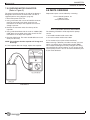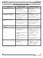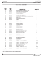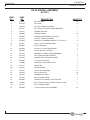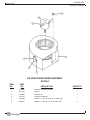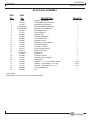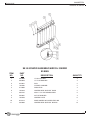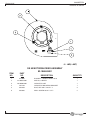
1
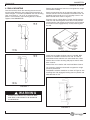
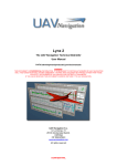
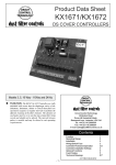
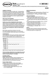
OWNER’S MANUAL
COMMERCIAL AIR CLEANER
MODELS:
SE-40/VARIABLE SPEED
SE-50/ 3 SPEED
KNOW YOUR EQUIPMENT
READ THIS MANUAL FIRST.
Your SMOKEETER system should provide many years of trouble-free service. This manual will help you understand the operation of your SMOKEETER unit. It will also help you
understand how to maintain it in order to achieve top performance. For quick future reference, fill in the system and filter information in the spaces below. Should you need assistance, call the United Air Specialists, Inc. customer service number shown below. To expedite your service, have the following information available when contacting UAS.
UNIT ORDER #: ________________________________________________________
UNIT MODEL #:_________________________________________________________
UNIT SERIAL #:_________________________________________________________
SYSTEM ACCESSORIES:
______________________________________________________________________
______________________________________________________________________
______________________________________________________________________
INSTALLATION DATE: ___________________________________________________
CUSTOMER SERVICE
1-800-237-9199
SAFETY PRECAUTIONS
We have provided many important safety messages in this manual and on the SMOKEETER Electronic Air Cleaner. Always
read and obey all safety messages.
!
This is the safety alert symbol.
This symbol alerts you to potential hazards that can kill or hurt you and others. All safety messages will follow the
safety alert symbol and the word “DANGER”, “WARNING”, or “CAUTION”. These words mean:
Indicates a hazardous situation which, if not avoided, will result in death or
serious injury.
!
DANGER
!
WARNING
Indicates a potentially hazardous situation which, if not avoided, could result
in death or serious injury.
!
CAUTION
Indicates a potentially hazardous situation which, if not avoided, may result
in minor or moderate injury.
CAUTION
CAUTION used without the safety alert symbol indicates a potentially
hazardous situation which, if not avoided, may result in property damage.
IMPORTANT SAFETY INSTRUCTIONS
!
WARNING
To reduce the risk of fire, electric shock, or injury when using the air cleaner, follow these basic precautions:
• Use nonflammable cleaners.
• Use two or more people to move and install the
SMOKEETER system.
• Do not collect emissions which are explosive.
• The air cleaner must be properly grounded.
• Keep flammable materials and vapors, such as gasoline,
away from air cleaner.
• Disconnect power before servicing.
• The unit should be inspected frequently and dirt removed
to prevent excessive accumulation which may result in
flash-over or fire damage.
• Replace all access panels before operating.
• Wear protective clothing and safety glasses when handling
collection components or servicing the air cleaner.
• The SMOKEETER System should not be used for support
of personnel or material.
• Electrical connections should only be made by qualified
personnel and be in accordance with local and national
codes and regulations.
• Operate only in a safe and serviceable condition.
• Do not use in explosive atmospheres.
i
TABLE OF CONTENTS
1.0
IMPORTANT NOTICE......................................................................................3
2.0
INSPECTION OF EQUIPMENT.......................................................................3
3.0
HOW YOUR AIR CLEANER OPERATES .......................................................3
3.1 COMPONENTS THAT MAKE IT WORK ...................................................3
4.0
INSTALLATION ................................................................................................3
4.1 WALL MOUNTING.....................................................................................4
4.2 SUSPENSION ...........................................................................................5
5.0
OPERATION ....................................................................................................5
6.0
CLEANING.......................................................................................................5
6.1 HOW TO REMOVE COMPONENTS.........................................................5
6.2 CLEANING.................................................................................................6
7.0
PERIODIC MAINTENANCE AND TROUBLESHOOTING...............................7
7.1 COMPONENT FUNCTION ........................................................................7
7.2 HOW THE HIGH VOLTAGE IS SUPPLIED TO THE COMPONENTS......7
7.3 TOOLS REQUIRED FOR TROUBLESHOOTING .....................................7
7.4 HOW TO MEASURE HIGH VOLTAGE......................................................7
7.5 MEASURING HIGH VOLTAGE..................................................................7
7.6 IONIZER VOLTAGE ...................................................................................7
7.7 CELL VOLTAGE.........................................................................................7
7.8 CHECKING THE POWER SUPPLY OUTPUT ..........................................8
7.9 CHECKING LAMP TERMINAL OUTPUT ..................................................8
7.10 CHECKING MOTOR CAPACITOR..........................................................9
8.0
PARTS ORDERING .........................................................................................9
9.0
TROUBLESHOOTING TABLE.......................................................................10
10.0 ILLUSTRATED PARTS .............................................................................11-22
11.0 WIRING DIAGRAM........................................................................................23
SMOKEETER®
Electronic Air Cleaner
Revised 12/05
SPECIFICATIONS
POWER REQUIREMENTS
AIR HANDLING CAPACITY
115 VAC, 60 HZ
6.0 Amps (max.)
Low - 450 to 950 CFM*
POWER CONSUMPTION
WEIGHT
690 Watts (max.)
Hanging …… 113 lbs. (51 kg)
Shipping …… 120 lbs. (54 kg)
MODEL SE 40
DIMENSIONS
Height
12 7/8"
(33 cm)
Width
21"
(53 cm)
Length
40"
(102 cm)
*CFM is variable
POWER REQUIREMENTS
AIR HANDLING CAPACITY
115 VAC, 60 HZ
8.4 Amps (max.)
High speed tap - 1,500 CFM
Medium speed tap - 1,050 CFM
Low speed tap - 600 CFM
POWER CONSUMPTION
WEIGHT
900 Watts (max.)
Hanging …… 140 lbs. (63.5 kg)
Shipping …… 151 lbs. (68.5 kg)
MODEL SE 50
DIMENSIONS
Height
20"
(51 cm)
Width
191/2"
(50 cm)
Length
40"
(102 cm)
1
SMOKEETER®
Electronic Air Cleaner
Revised 12/05
DIMENSIONS
SE 40
SE 50
2
SMOKEETER®
Electronic Air Cleaner
Revised 12/05
1.0 IMPORTANT NOTICE
This manual contains important safety information and
precautionary measures. Read this manual thoroughly
and comply with the instructions given. It is impossible
to list all potential hazards associated with every dust
collection system in each application. Proper use of the
equipment must be discussed with United Air
Specialists, Inc. (UAS) or your local representative.
Operating personnel must be aware of, and adhere to,
the most stringent safety procedures.
2.0 INSPECTION OF EQUIPMENT
Upon receipt of your unit, check for any shipping damage. A
damaged carton indicates that the equipment may have
received rough handling during shipping that may have
caused possible internal damage. Notify your delivery
carrier and enter a claim if any damage is found.
3.0 HOW YOUR AIR CLEANER
OPERATES
The motor/blower assembly draws air through an aluminum
mesh filter which removes the larger particles in the
contaminated air. As the particles pass through the ionizer
section, they are given an intense positive charge. These
charged particles are then collected on cell plates. The
clean air is redistributed into the room by adjustable outlet
diffusers.
3.1 COMPONENTS THAT MAKE IT WORK
PREFILTER traps the larger particles and evenly distributes
the air across the ionizing section to maximize efficiency.
IONIZER is made up of fine tungsten wires supported
between metal plates. When high voltage is applied to
these parts, a “corona” field is generated which imparts a
high-voltage charge on particles that pass through it.
COLLECTION CELL is made up of a series of convoluted
metal plates. These plates act like a magnet and attract the
charged particles removing them from the air. The plates
are alternately charged positive and ground. The positive
plates repel the particles while the ground plates attract
them, yielding a very high efficiency.
NOTE: The SE 40 contains an ionizer and collection cell
as a one piece assembly known as a unicell.
SPEED CONTROL SWITCH allows you to adjust the airflow
between 450 and 950 CFM on the SE 40. The switch on the
SE 50 allows you to select 3 of 5 motor speed taps. The SE
50 is shipped from the factory with the switch wired to the
low, medium and high speed motor taps. By repositioning
the wire connectors at the motor the medium-low or
medium-high taps can be used instead of the factory
selected low, medium or high.
MOTOR/BLOWER produces air movement by a low speed,
dynamically-balanced, forward-curved blower. The direct
drive motor is thermally protected.
4.0 INSTALLATIONS
NOTE: This product has been designed specifically for
commercial applications, such as offices, night
clubs, bowling centers and bingo halls. United
Air Specialists assumes no responsibility for
those applications unlike the aforementioned.
!
CAUTION
TO REDUCE THE RISK OF ELECTRIC SHOCK, THIS
EQUIPMENT HAS A GROUNDING-TYPE PLUG THAT
HAS A THIRD (GROUNDING) PIN. THIS PLUG WILL
ONLY FIT INTO A GROUNDING-TYPE POWER
OUTLET. IF THE PLUG DOES NOT FIT INTO THE
OUTLET, CONTACT QUALIFIED PERSONNEL TO
INSTALL THE PROPER OUTLET. DO NOT ALTER
THE PLUG IN ANY WAY.
SMOKEETER is designed to draw the contaminated air
through the unit and exhaust clean air back into the room.
The clean air is used to push contaminated air around the
room to the inlet of the unit. Directions of air patterns and
proper placement of the unit should be established by your
local SMOKEETER distributor or by United Air Specialists,
Inc.
The unit can be installed by mounting on a wall or
suspending from the ceiling joists/structure.
3
SMOKEETER®
Electronic Air Cleaner
Revised 12/05
4.1 WALL MOUNTING
Level and securely attach the mounting cleat to the wall,
ensuring given dimension from ceiling to bolt centerline as
shown in Figure 1. The holes provided on the wall mounting
cleat are spaced 12", 16" or 24" on center mounting
patterns. Use fasteners and anchoring devices to ensure
support of the SMOKEETER.
Remove the components from the unit to lighten the weight
and facilitate handling.
Attach the mounting cleat to the top back edge of the unit
with two 3/8-16 x 3/4" hex head bolts and washers that are
provided. Install two 3/8-16 x 1-1/4" leveling screws in the
bottom outside holes. Refer to Figure 2.
Place the unit on a lifting device. Position the lifting device
under the wall mounting cleat. Raise the unit into position
and engage the wall mounting cleat with the cleat mounted
to the unit. Ensure engagement by visually checking from
the end.
FIGURE 2
Check level and adjust leveling screws as needed. Mark
location on hold-down fastener on the wall. The hole is
located behind the collection cell and marked with a label.
Remove the unit from mounting and prepare wall for holddown fastener.
Reinstall the unit as before and install hold-down fastener.
The fasteners should now be tested to support the weight
previously mentioned.
Completed installation should be as shown in Figure 3, with
mounting cleat fully engaged, leveling screw in position and
hold-down bolt in wall.
FIGURE 1
!
WA R N I N G
ATTACH WALL MOUNT TO CLEAT TO WALL
AND TEST LOAD CAPACITY AS SHOWN IN
ILLUSTRATION.
FIGURE 3
4
SMOKEETER®
Electronic Air Cleaner
Revised 12/05
4.2 SUSPENSION
Threaded rod, wire or eyebolts and chain may be used for
hanging the unit. Four “knockouts”, located as shown in
Figure 4, must be removed.
It is recommended that a nut on the inside and outside of
the cabinet be used to lock the fastener in place.
Refer to Figure 4.
Test the unit for secure support.
5.0 OPERATION
For best results and to assure maximum air quality, your
SMOKEEETER unit should be started before the air
becomes contaminated. An indicator lamp indicates that
high voltage to the components is on. A variable or multispeed control switch allows you to adjust the blower speed.
If you notice a decrease of cleaning efficiency, increase the
blower speed to increase effectiveness of the unit.
FOR YOUR INFORMATION — The equipment has been
thoroughly tested prior to shipment from the factory. Even
so, there may be some initial arcing of the components at
start-up. The noise should cease after a few minutes of
operation.
6.0 CLEANING
!
CAUTION
SERVICING THIS PRODUCT FOR PURPOSES
OTHER THAN ROUTINE CLEANING OF THE
COLLECTION COMPONENTS SHOULD BE
PERFORMED BY TRAINED AUTHORIZED
SERVICE PERSONNEL. ANY EFFORT TO
EXCEED THIS SERVICE (BY NON-QUALIFIED
PERSONNEL) MAY LEAD TO BODILY INJURY
AND/OR EQUIPMENT FAILURE.
This section is defined for cleaning and periodic
maintenance. The internal components must be removed
prior to cleaning.
!
CAUTION
THE UNIT SHOULD BE INSPECTED
FREQUENTLY AND DIRT REMOVED TO
PREVENT EXCESSIVE ACCUMULATION WHICH
MAY RESULT IN FLASHOVER OR FIRE
DAMAGE. AN ELECTRICAL INTERLOCK IS
PROVIDED FOR PROTECTION — DO NOT
DEFEAT ITS PURPOSE.
6.1 HOW TO REMOVE COMPONENTS
FIGURE 4
1. Turn off the unit.
• Open the access door.
• For added safety, manually discharge the ionizer and
collection cell/unicell in the following manner. Place the
blade of a common screwdriver (with insulated handle)
across the ionizer wire support and then the ionizer
frame. Next, place the screwdriver blade across the cell
end plate and then across a cell “hot” plate. This will
remove any residual charge that may not have bled off.
Refer to figure 5.
2. Slide components from the cabinet.
5
SMOKEETER®
Electronic Air Cleaner
Revised 12/05
6.2 CLEANING
Major cleaning is confined to the prefilter, ionizer, collection
cell and the inside cabinet. These should be cleaned
periodically to assure continued efficiency. Cleaning may be
required from once a month to once every four months
depending on the air quality.
NOTE: The carbon filter cannot be cleaned and needs to
be replaced as required.
1. Disconnect power to unit and remove components.
2. The ionizer, collection cell/unicell and prefilter can be
cleaned by soaking in a hot solution of SMOKEETER
brand detergent for 30 to 60 minutes. If possible, agitate
the solution to aid in dirt removal. If agitation is not
possible, soaking time should be increased.
!
NOTE: The SE 40 contains an ionizer and collection cell as a one piece assembly
known as a unicell.
CAUTION
DO NOT USE TEMPERATURE EXCEEDING
160˚F AND DO NOT STEAM CLEAN AS THIS
MAY CAUSE PERMANENT DAMAGE TO THE
COMPONENTS. IF DETERGENT OTHER THAN
SMOKEETER BRAND IS USED, CARE MUST
BE TAKEN TO ASSURE THAT IT CONTAINS
AN ALUMINUM INHIBITOR SO THAT IT DOES
NOT ATTACK THE ALUMINUM COMPONENTS.
BE SURE TO FOLLOW MANUFACTURER’S
CLEANING INSTRUCTIONS.
3. Remove the components from the detergent bath and
immediately flush away any residue and rinse thoroughly
with clear hot (less 160˚F) water. Shake off excess water
and let components dry for 30 to 60 minutes. Set the cell
so that its plates are in a vertical position for drainage.
4. Vacuum clean the interior of the cabinet and clean off all
electrical connections before reinstalling the components.
5. Reinstall the components into the cabinet.
6. Apply power to unit and confirm indicator light is
illuminated.
FIGURE 5
6
SMOKEETER®
Electronic Air Cleaner
Revised 12/05
7.0 PERIODIC MAINTENANCE AND
TROUBLESHOOTING
The following sections are for the use
of trained service personnel only.
!
WA R N I N G
THE FOLLOWING PROCEDURES WILL
EXPOSE HAZARDOUS LIVE AND MOVING
PARTS. DISCONNECT AIR CLEANER BEFORE
PROCEEDING.
7.2 HOW THE HIGH VOLTAGE IS SUPPLIED
TO THE COMPONENTS
The power supply supplies high voltage DC to the ionizer
and collection cell by the use of high voltage lead wires.
Two separate terminals are used on the output side of the
supply. Terminal #8 supplies nominal 11,000 volts DC
positive to the ionizer. Terminal #7 supplies 5,500 volts DC
to the cell.
7.3 TOOLS REQUIRED FOR
TROUBLESHOOTING
• Screwdriver — (common type) 8" or longer with insulated
handle.
• Volt-Ohm Meter — for measuring low voltage input (115
VAC), continuity (OHMS) and low voltage DC.
All SMOKEETER air cleaners are manufactured to give
years of trouble-free performance. As with any piece of
equipment, however, breakdowns can occur. Due to the
simplicity of design, breakdowns are restricted to the
following components:
• the motor/blower*
• the power supply
• ionizer
• collection cell/unicell
• blower control switch
• safety switch
• indicator lamp
• High Voltage Probe (DC) positive polarity — for checking
the high voltage power supply (minimum range from 0 to
15 KV DC).
This section covers the troubleshooting procedure and a
table which will enable you to determine the cause of most
problems. Refer to Section 8.0 for replacement parts.
1. Turn the unit off and open the access door. This will
disengage the safety interlock.
*These models are equipped with permanently lubricated
motors. No further oiling is required.
7.1 COMPONENT FUNCTION
1. Power Supply - the electrical circuit is designed around
the power pack which contains the necessary
components to convert 115 Volts, single-phase, 60 hertz
to the high voltage DC required for the components.
2. Ionizer - the ionizing section supports several tungsten
wires charged positive to a nominal 11,000 volts DC. The
baffle plates parallel to the wire are at ground potential.
The ionizer’s function is to electrically charge the
contaminated particles as they pass through the ionizer.
3. Collection Cell - the collecting section consists of
alternately charged plates. Plates are alternately charged
with a nominal 5,500 volts DC positive. The field between
the plates forces the charged particles to the ground
plates removing them from the airstream.
NOTE: The SE 40 contains an ionizer and collection cell
as a one piece assembly known as a unicell.
4. Motor/Blower - draws in contaminated air and exhausts
clean air through the outlet.
7.4 HOW TO MEASURE HIGH VOLTAGE
To accurately measure the high voltage, a 0 to 15 KV
minimum scale high voltage probe capable of measuring
positive polarity is required.
7.5 MEASURING HIGH VOLTAGE
(Refer to Figure 6)
2. Connect the ground clip of the positive polarity probe to
the side of the cabinet.
!
CAUTION
Always ground the high-voltage probe to a
solid ground connection on the metal cabinet.
3. Turn unit control switch on and cautiously engage the
safety interlock switch.
!
CAUTION
Be sure to disengage safety interlock switch
after measuring voltages.
7.6 IONIZER VOLTAGE
Place the probe’s tip on the ionizer (refer to Figure 6) and
measure the positive DC voltage. The voltage should read
10 to 11 KV DC.
• If measurements are abnormal, refer to the
troubleshooting table (page 10) for cause and correction.
7.7 CELL VOLTAGE
Place the probe’s tip on one of the charged plates. The
voltage reading should be 4 to 6 KV DC.
• If measurements are abnormal, refer to the
troubleshooting table (page 10) for cause and correction.
7
SMOKEETER®
Electronic Air Cleaner
Revised 12/05
• Output reading without the components should read 10
to 12 KV DC positive.
3. To measure the collection cell output voltage, place the
probe’s tip on the cell high voltage contact (follow #7
wire).
• Output without the components should read 5 to 7 KV
DC positive.
FIGURE 7
(Contact point locations may vary)
7.9 CHECKING LAMP TERMINAL OUTPUT
(Refer to Figure 8)
Disconnect unit indicator lamp (neon lamp).
Connect a good neon lamp to supply terminal “light” and to
pack terminal “GND” or cabinet ground. If lamp does not
light, replace power supply. If lamp lights, check wiring
and unit indicator lamp.
FIGURE 6
7.8 CHECKING THE POWER SUPPLY OUTPUT
(Refer to Figure 7)
1. Remove the components from the cabinet.
2. Engage the safety interlock switch and measure the
output from the ionizer terminal of the power supply by
placing the probe’s tip on the ionizer high voltage contact
located on inside back wall of cabinet (follow #8 wire).
8
FIGURE 8
SMOKEETER®
Electronic Air Cleaner
Revised 12/05
7.10 CHECKING MOTOR CAPACITOR
(Refer to Figure 9)
The motor capacitor located on the side of the blower is
designed to start and run the motor when 115 VAC is
supplied (refer to wiring diagrams, page 23).
1. Disconnect power to the unit.
2. Using a volt meter with a scale of 120 VAC minimum,
place the two leads of the meter across the two
connections at the top of the capacitor to ensure no
voltage is present.
3. Remove the two brown wires from the top of the
capacitor.
8.0 PARTS ORDERING
Replacement parts can be ordered by contacting:
Pure n Natural Systems, Inc.
1-800-237-9199
www.purennatural.com
ATTN: CUSTOMER SERVICE DEPARTMENT
4. Using a Volt-Ohm Meter with the scale on 10,000 (10K)
OHM, place the two leads of the meter across the two
connections at the top of the capacitor.
The following information will be required for prompt
service:
5. Read the VOM scale. The meter should deflect to 0 and
slowly rise to infinity.
2. Unit serial number inside access door.
NOTE: This indicates that the capacitor will charge and
discharge.
6. If the capacitor does not charge, replace the capacitor.
1. Unit model number inside access door.
3. Part number of part (refer to Illustrated Parts).
When returning a defective part under warranty, you must
call for a customer return authorization number (RMA).
This number should appear on the package that is being
returned. With this control number, we can assure you will
receive prompt service. You can also return defective parts
to your local distributor.
FIGURE 9
9
SMOKEETER®
Electronic Air Cleaner
Revised 12/05
9.0 TROUBLESHOOTING TABLE*
PROBLEM
A. Control switch on, indicator lamp
off, blower operates.
POSSIBLE CAUSE
CORRECTIVE ACTION
1. Defective lamp.
1. Replace lamp.
2. Faulty connection to lamp.
2. Check connection to lamp.
3. Loss of high voltage.
3. Check power supply.
4. Loss of continuity of high voltage.
4. Refer to Problem “E”. Follow
steps 1-4.
1. Motor faulty.
1. Replace motor.
2. Foreign object blocking motor.
2. Clean foreign object from motor.
3. Faulty control switch
3. Replace control switch.
4. Connector not properly connected
at control switch
4. Check connection at control switch.
1. Loss of input 115 VAC.
1. Determine loss of input voltage.
2. Safety interlock switch not engaged.
2. Engage safety interlock switch.
3. Safety interlock switch defective.
3. Replace safety interlock switch.
4. Control switch defective.
4. Replace control switch.
D. Motor operates on low or high
speed only.
1. Control switch defective.
1. Replace control switch.
E. Poor air quality.
1. Ionizer/collection cell/unicell dirty.
1. Clean components.
2. Ionizer/collection cell/unicell
malfunctioning.
2. Check for:
A. Foreign matter between plates.
B. Ionizer wire loose or broken.
C. Defects in insulators.
3. Components installed backwards or
upside down.
3. Install components as shown in
Section IX.
4. High voltage contacts dirty.
4. Clean high voltage contacts.
5. Unit being operated on too low of
a speed.
5. Increase blower speed.
6. Placement of unit not creating a
good air pattern.
6. Contact your local distributor or
United Air Specialists.
1. Loss of input 115 VAC.
1. Determine loss of input voltage.
2. Ionizer/collection cell/unicell
malfunctioning.
2. Check for:
A. Foreign matter between plates.
B. Ionizer wire loose or broken.
C. Defects in insulators.
3. Power supply defective.
3. Replace power supply.
B. Control switch on, indicator lamp
on, blower does not operate.
C. Control switch on, motor and
lamp off.
F. Loss of high voltage output.
*Refer to wiring diagram and illustrated parts.
10
SMOKEETER®
Electronic Air Cleaner
Revised 12/05
10.0 ILLUSTRATED PARTS
SE 40 FINAL ASSEMBLY
11
SMOKEETER®
Electronic Air Cleaner
Revised 12/05
SE 40 FINAL ASSEMBLY
ITEM
NO.
PART
NO.
1
10-2820
MOTOR/BLOWER ACCESS DOOR (WG)
1
2
10-2821
COMPONENT ACCESS DOOR (WG)
1
3
02-2544
MOTOR/BLOWER ASSEMBLY +
1
4
02-1321
UNICELL ASSEMBLY +
1
5
02-2725
CENTER POST ASSEMBLY +
1
6
21-1218
POWER SUPPLY (GREY PLASTIC CONSTRUCTION)
1
7*
03-1078
WIRE KIT HV
1
8*
03-0667
INSTALLATIONS PARTS KIT
1
9
33-0156
GRILLE
1
10
33-0054
FILTER — MESH
1
11
33-0053
FILTER — CARBON
1
12
20-2922
CORD-IEC, 90 DEG.
1
13*
10-2799
HANGING BRACKET
2
14
37-0013
INSULATOR
2
15
36-0014
CONTACT SPRING
2
16
36-0077
GROUND SPRING
1
17
10-2574
BLOWER SUPPORT
1
20
30-0031
SCREW OVAL HD #8-31 X 3/4" L
2
21
30-0335
SCREW, HEX HD #8-32 X 3/8" L
4
22
30-0206
SCR, FL HD #8-32 X 3/8" L
12
23
30-0202
FASTENER
2
24
20-2921
IEC 320 POWER INLET
1
26
20-0155
BUSHING, 1/2" DIA.
1
27
35-0191
ACTUATOR INTLK SWITCH
1
30
30-0163
CLIP SOUTHCO
1
32
41-0674
NAMEPLATE
1
33
42-0206
GASKET — 1" X 1" POLYESTER
.83 FT.
34
42-0156
GASKET — NEOPRENE 1/16" X 3/8"
2.6 FT.
35
42-0158
GASKET — NEOPRENE 1/8" X 1/2"
1.0 FT.
37
30-0119
SCR, PAN HD. #8-32 X 5/16"
2
38
30-0363
SCR, TEK #10-16 X 3/4"
3
40
42-0149
GASKET — BUNA-N 3/16" X 1-1/2"
.25 FT.
43
42-0176
GASKET — 1/2" X 1" POLYESTER
1.0 FT.
DESCRIPTION
* NOT SHOWN
+ SEE DETAIL PARTS LIST ON THE FOLLOWING PAGES
12
QUANTITY
SMOKEETER®
Electronic Air Cleaner
Revised 12/05
SE 40 UNICELL ASSEMBLY
02-1321
13
SMOKEETER®
Electronic Air Cleaner
Revised 12/05
SE 40 UNICELL ASSEMBLY
02-1321
14
ITEM
NO.
PART
NO.
1
35-0067
CELL SPACER
2
35-0175
CELL ROD
8
3
10-1373
AIR FOIL CORNER CHANNEL
1
4
02-1318
CELL ROD TO CONTACT WIRE ASSEMBLY
1
5
10-1375
IONIZER SUPPORT
2
6
36-0004
IONIZER SPRING
10
7
03-0393
IONIZER WIRE ASSEMBLY, SET OF 5
1
8
10-1374
AIR FOIL CORNER CHANNEL
1
9
37-0014
INSULATOR, IONIZER STAND OFF (1/2" DIA. 2"L)
4
10
30-0142
#8-32 X 3/8" PAN HEAD SCREW
8
11
30-0081
#8 FLAT WASHER
4
12
30-0520
#10-32 X 1/2" HEX HEAD SCREW
4
13
30-0500
#10-32 HEX NUT, LOCKING
4
14
02-1318
IONIZER TO CONTACT WIRE ASSEMBLY
1
15
35-0174
CELL HIGH-VOLTAGE CONTACT
1
16
35-0194
IONIZER HIGH-VOLTAGE CONTACT
1
17
30-0449
1/4-20 HEX LOCK NUT
1
18
37-0008
INSULATOR, CELL (DISC TYPE)
8
19
10-1372
END PLATE
2
20
20-0155
HOLE BUSHING
2
21
10-0158
CELL PLATE (GROUND)
15
22
10-0157
CELL PLATE (HOT)
20
23
10-1376
IONIZER/CELL PLATE
4
24
10-2283
CELL CORNER STRAP
1
25
03-0306
CONTACT KIT, UNICELL HIGH-VOLTAGE
1
25A
37-0042
CELL HIGH-VOLTAGE CONTACT MOUNT PLATE
1
26
10-1378
CELL CORNER ANGLE
1
27
30-0030
1/4-20 LOCKNUT (NYLON INSERT)
15
DESCRIPTION
QUANTITY
156
SMOKEETER®
Electronic Air Cleaner
Revised 12/05
SE 40 MOTOR/BLOWER ASSEMBLY
02-2544
ITEM
NO.
PART
NO.
DESCRIPTION
1
32-0083
BLOWER — DIRECT DRIVE
1
2
02-1327
MOTOR
1
3
20-0569
CAPACITOR
1
4
20-1298
CAPACITOR STRAP
1
5
30-0335
SCREW — HEX HD #8-32 X 1/2" SELF TAP
2
6
30-0077
SCREW — HEX HD 1/4" X 5/8" SELF TAP
3
QUANTITY
15
SMOKEETER®
Electronic Air Cleaner
Revised 12/05
SE 40 CENTER POST ASSEMBLY
02-2725
16
ITEM
NO.
PART
NO.
1
10-2825
EXTRUSION, CENTER POST
1
2
02-1326
SWITCH — CONTROL VARIABLE SPEED
1
3
20-0229
LIGHT — PILOT, AMBER
1
4
20-0560
SWITCH — INTLK — DP NO
1
5
30-0164
RETAINER, SOUTHCO
1
6
30-0165
SCREW, WING HEAD
1
7
30-0301
SCREW — PAN HD. #6-32 X 1 1/4" L
2
8
30-0038
LOCKWASHER — #6, DOUBLE
1
9
30-0345
TINNERMAN NUT — #6 INT TOOTH
2
10
37-0055
INSULATION — SWITCH
1
11
39-0105
LATCH, MAGNETIC
2
12
30-0076
SCREW — #10-32 X 3/8" GROUND (GREEN)
1
13
02-2598
WIRE HARNESS ASSEMBLY
1
14
30-0036
LOCKWASHER — #10 EXT. TOOTH
3
15
39-0120
SPEED CONTROL KNOB
1
DESCRIPTION
QUANTITY
SMOKEETER®
Electronic Air Cleaner
Revised 12/05
SE 50 FINAL ASSEMBLY
17
SMOKEETER®
Electronic Air Cleaner
Revised 12/05
SE 50 FINAL ASSEMBLY
ITEM
NO.
PART
NO.
1
2
3
4
5
6
7
8
9
10
11
12
13*
14
15
16
17
18-0800
10-2823
10-2822
02-10650-0001
02-10651-0001
33-0039
21-1218
33-0001
02-0089
02-0086
33-0007
10-2606
10-2799
20-2922
20-2921
36-0077
37-0013 OR
37-0063
36-0008
35-0191
41-0674
42-0206
42-0156
42-0158
03-0030
30-0163
18
19
20*
21
22
23
24*
25
DESCRIPTION
CABINET WELDMENT
COMPONENT ACCESS DOOR
BLOWER ACCESS DOOR
MOTOR/BLOWER ASSEMBLY +
CENTER POST ASSEMBLY +
DISCHARGE GRILL
POWER SUPPLY
MESH FILTER
IONIZER ASSEMBLY +
COLLECTION CELL +
CARBON FILTER
BLOWER SUPPORT ANGLE
HANGING BRACKET
CORD-IEC, 90 DEG.
IEC 320 POWER INLET
SPRING GROUND
INSULATOR
INSULATOR
CONTACT SPRING
ACTUATOR INTLK SWITCH
NAMEPLATE
GASKET — 1" X 1" POLYESTER FOAM
GASKET — NEOPRENE 1/16" X 3/8"
GASKET — NEOPRENE 1/8" X 1/2"
HV LEAD ASSEMBLY
CLIP
* NOT SHOWN
+ SEE DETAIL PARTS LIST ON THE FOLLOWING PAGES
18
QUANTITY
1
1
1
1
1
1
1
1
1
1
1
1
2
1
1
2
1
1
2
1
1
1.5 FT.
2.4 FT.
1.6 FT.
1
1
SMOKEETER®
Electronic Air Cleaner
Revised 12/05
SE 50 IONIZER ASSEMBLY/AIRFOIL IONIZER
02-0089
ITEM
NO.
PART
NO.
1
30-0030
1/4-20 LOCK NUT
4
2
30-0049
1/4" FLAT WASHER
4
3
35-0027
ROD
2
4
10-0465
CORNER CHANNEL
2
5
37-0004
INSULATOR
4
6
10-0570
IONIZER WIRE SUPPORT RAILS
2
7
30-0142
#8-32 X 1/2" PAN HEAD SCREW
8
8
30-0081
#8 FLAT WASHER
4
9
10-0420
IONIZER PLATE
6
10
02-6274
WIRE-IONIZER W/LOOPED END 10M
7
11
36-0004
IONIZER WIRE SUPPORT SPRING
14
DESCRIPTION
QUANTITY
19
SMOKEETER®
Electronic Air Cleaner
Revised 12/05
SE 50 CELL ASSEMBLY/CP COLLECTION CELL
02-0086
20
ITEM
NO.
PART
NO.
1
30-0030
1/4-20 LOCK NUT
16
2
37-0008
INSULATOR
8
3-A
10-0564
HANDLE
1
3-B
10-0559
COVER PLATE, HANDLE
1
4
10-0348
END PLATE
2
5
41-0330
WARNING LABEL
1
6
10-0157
HOT CELL PLATE
33
8
10-0158
GROUND CELL PLATE
32
9
35-0067
SPACER
260
10
35-0049
CORNER ANGLE
4
11
35-0045
CELL ROD
8
DESCRIPTION
QUANTITY
SMOKEETER®
Electronic Air Cleaner
Revised 12/05
SE 50 CENTER/POST ASSEMBLY
02-10651-0001
ITEM
NO.
PART
NO.
1
10-11706-001
2
DESCRIPTION
QUANTITY
CENTER POST
1
02-1231
SWITCH — CONTROL 3-SPEED
1
3
20-0229
LIGHT — PILOT, AMBER
1
4
20-0560
SWITCH — INTLK-DP NO
1
5
30-0164
RETAINER, SOUTHCO
1
6
30-0165
SCREW, WING HEAD
1
7
30-0301
SCREW — PAN HD. #6-32 X 1 1/4" L
2
8
30-0038
LOCKWASHER — #6 INT. TOOTH
2
9
30-0345
TINNERMAN NUT — #6, DOUBLE
2
10
37-0055
INSULATION — SWITCH
1
11
39-0105
LATCH, MAGNETIC
2
12
03-10446-0001
WIRE KIT, LOW VOLTAGE
1
13
39-0120
KNOB-SWITCH
1
21
SMOKEETER®
Electronic Air Cleaner
Revised 12/05
SE 50 MOTOR/BLOWER ASSEMBLY
02-10650-0001
22
ITEM
NO.
PART
NO.
1
32-0085
2
DESCRIPTION
QUANTITY
BLOWER — DIRECT DRIVE 10-10
1
22-10018-0001
MOTOR, 5-SPEED
1
3
20-10090-0001
CAPACITOR, 5NF
1
4
20-1298
CAPACITOR MOUNTING BRACKET
1
5
30-0233
BOLT, HEX HD 1/4-20 X 1" L
3
6
30-0335
DRILL SCREW #8-32 X 1/2" L
2
SMOKEETER®
Electronic Air Cleaner
Revised 12/05
11.0 WIRING DIAGRAM
MODEL SE 40
41-2488
MODEL SE 50
41-10028
23
UNITED AIR SPECIALISTS, INC.
LIMITED WARRANTY
UAS warrants to the original purchaser that all equipment will be free from defects in materials and
workmanship for one year from the date of shipment from UAS (three years for Smokeeter® and
VisionAir™ models other than CC and DC series) and that major structural components on SFC and MCB
series will be free from defects in materials and workmanship for ten years from the date of shipment from
UAS. This warranty applies only if equipment is properly installed, maintained, and operated under normal
conditions and does not apply to damage caused by corrosion, abrasion, abnormal use or misuse,
misapplication, or normal wear and tear. This warranty will be void with respect to equipment that is subject
to unauthorized repairs or modifications. UAS makes no warranty as to goods manufactured or supplied by
others. This warranty is subject to any limitations in UAS’ quotation and may not be modified except by a
written instrument signed by the President or Vice President of Sales of UAS.
THIS WARRANTY IS EXCLUSIVE AND IN LIEU OF ALL OTHER WARRANTIES, WHETHER
WRITTEN, ORAL OR IMPLIED, INCLUDING ANY IMPLIED WARRANTY OF
MERCHANTABILITY, FITNESS FOR A PARTICULAR PURPOSE OR NONINFRINGEMENT.
As Purchaser's exclusive remedy for any defects in the equipment, UAS will exchange or repair any
defective parts during the warranty period, provided such parts are returned, prepaid, to UAS' factory. The
obligation of UAS is limited to furnishing replacement parts F.O.B. UAS' factory or making repairs at UAS'
factory of any parts that are determined, upon inspection by UAS, to be defective. In no event will UAS be
responsible for labor or transportation charges for the removal, reshipment or reinstallation of the parts.
IN NO EVENT WILL UAS BE RESPONSIBLE FOR ANY SPECIAL OR CONSEQUENTIAL
DAMAGES.
DISTRIBUTED BY:
Pure n Natural Systems, Inc.
National Phone: 1-800-237-49199
Telephone: (847) 470-1652 • Fax: (847) 470-1686
http://www.purennatural.com.
©1999, 2003, 2004, 2005 United Air Specialists
Part No. 44-10395-0001
12/05
United Air Specialists, Inc.
reserves the right to change
design or specifications
without notice.