1
Owner’s
Manual
Standard Burner Systems:
FOR INSTALLATION IN
SOLID-FUEL BURNING
FIREPLACES
G4-12(P)
G4-16/19(P)
G4-18/20(P)
G4-24(P)
G4-30(P)
G4-36(P)
G4-42(P)
G4-48(P)
G4-60(P)
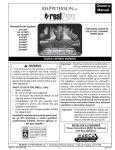
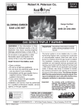
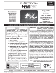
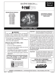
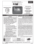
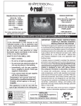
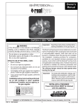
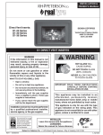
Woodland Oak (WOG4-24) Shown
G4/GX4 SERIES BURNER
Important: Read these instructions carefully before
starting installation of the gas log set.
WARNING
If the information in this manual is not followed
exactly, a fire or explosion may result, causing
property damage, personal injury, or loss of life.
This burner system is to be installed only in a solid-fuelburning fireplace with a working flue and constructed
of noncombustible material. Solid fuels shall not be
burned in a fireplace where this gas log set is installed.
The installation, including provisions for combustion,
ventilation air, and required minimum permanent vent
opening, must conform with the National Fuel Gas
Code (Z223.1) and applicable local building codes. A
damper stop clamp is included to maintain the minimum
permanent vent opening and to prevent full closure of
the damper blade. The chimney damper should be
fully opened when burning the log set. The log set is
designed to burn with yellow flames; thus, adequate
ventilation is absolutely necessary.
Do not store or use gasoline or other flammable
vapors and liquids in the vicinity of this or any
other appliance.
WHAT TO DO IF YOU SMELL GAS:
• Open a window.
• Do not try to light any appliance.
• Do not touch any electrical switch; do not
use any phone in the building.
• Immediately call the gas supplier from
a neighbor’s phone and follow the gas
supplier’s instructions.
• If you cannot reach the gas supplier, call the
fire department.
Installation and service must be performed
by an NFI Certified or other qualified
professional installer, service agency, or
the gas supplier.
Important: To comply with certification, listings, and
building code acceptance, and for safe
operation and proper performance,
ONLY Peterson parts and accessories
may be used with this gas log set.
INSTALLER & CONSUMER
These instructions MUST be retained
with this appliance.
We recommend that our gas
hearth products be installed
and serviced by professionals
who are certified in the U.S.
by the National Fireplace
Institute® (NFI) as NFI Gas
Specialists.
ROBERT H. PETERSON CO. • 14724 East Proctor Avenue • City of Industry, CA 91746
REV 5 - 1407290845
1
L-A2-013
IMPORTANT - Read This Manual Carefully Before Starting Installation of the Log Set
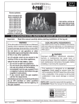
When the log set is burning, the fireplace
damper must be fully open. The Peterson RealFyre® gas log set is to be burned only in a fully
vented, noncombustible fireplace with damper and
chimney free of any obstructions. The fireplace
must be designed and approved to burn wood. As
with burning natural firewood, the Real-Fyre® log
set is designed to burn with yellow, smoky flames.
For this reason, it must be adequately vented. If
adequate ventilation is not provided as detailed
on this instruction, do not use this Real-Fyre®
log set. If fumes from the burner emerge into the
room when the damper is fully open, creating a
smell like a smoldering oil lamp, it indicates that
the fireplace draft is defective. Check chimney flue
for obstructions. Do not operate the log set until
the fireplace draft is corrected. Check with the
dealer or installer. Do not use firewood with the
gas log set.
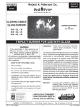
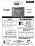
Some Available Log Styles:
Charred Series
Charred Oak (CHD)
Charred Split (CHS)
Charred Royal (CHB)
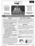
Classic Series
Golden Oak (R)
Post Oak (PO)
Emberwood (E)
Royal English Oak (B)
Mountain Oak (K)
Twisted Pine (C)
Designer Series
Golden Oak Designer Plus
(RDP)
Split Oak (S)
Split Oak Designer Plus
(SDP)
Woodland Oak (WO)
Designer (EXD)
Royal English Oak
Designer (BD)
Heritage Designer (HD)
White Birch (W)
Golden Oak Designer (RD6)
FOR YOUR SAFETY
Do not store or use gasoline or other flammable
vapors and liquids in the vicinity of this or any other
appliance.
TABLE OF CONTENTS
PARTS LIST
IMPORTANT INFORMATION
FIREPLACE REQUIREMENTS
INSTALLATION
INSTALLING THE BURNER
LOG PLACEMENT
GRANULE, EMBER, AND GRATE PLACEMENT
OPTIONAL CHARRED SERIES INSTALLATION
LIGHTING INSTRUCTIONS
MAINTENANCE & SERVICE
OPTIONAL CONTROLS
OPTIONAL PETERSON VALVES & SAFETY PILOT KITS*
TROUBLESHOOTING YOUR GAS LOG SET
TROUBLESHOOTING YOUR GAS LOG SET (Continued)
WARRANTY
REV 5 - 1407290845
2
3
4
4
5
5
6
6
8
9
10
10
11
12
13
14
L-A2-013
PARTS LIST
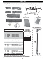
Before beginning installation, be sure the gas log set is complete by comparing its contents with this PARTS
LIST. The RG4-24 set is listed and illustrated. Your parts may differ depending upon the log style and size of
the set. Be sure you know the model number and size of your set when ordering replacement or optional parts
and accessories.
13
6
4
14
12
3
5
2
10
Glowing embers
11
Sand or vermiculite
granules
1
8
7
9
Item
No.
Part No.
Description
1.
RL-24BF
Golden Oak front bottom log 24"
2.
RL-20BR
Golden Oak rear bottom log 20"
3.
RL-15TL
Golden Oak top log 15"
4.
RL-15TR
Golden Oak top log 15"
5.
RL-9TL
Golden Oak top log 9"
6.
RL-9TR
Golden Oak top log 9"
7.
400768
Stabilizer clips with screws and nuts
(replacement package also includes
a damper clamp)
8.
DC-1
Damper clamp
9.
CK-14-12
Connector kit (with adapters)
10.
EM-1
Glowing Embers (2)
11.
CS-12
Select sand granules (natural)
or
LF-15
Vermiculite granules (propane)
12.
AB-2-29
Fuel injector (natural)
or
AM-2-50
Air mixer (propane)
13.
SD-24
Fireplace grate 24"
or
SX-24
Heavy-duty fireplace grate (GX4 log
sets)
14.
GG-24
Burner pan, glowing embers 24"
Note:
Connector kit
9A
The log set is
purchased and
packaged separately.
Golden Oak log set
shown here. Styles
and sizes will vary
depending upon the
log set ordered. If
the log set ordered
includes placement
instructions; follow
those instructions.
9B
9C
Values in bold change with burner size, model, and log set.
Replacement parts can be ordered from your local Real-Fyre® dealer.
REV 5 - 1407290845
3
L-A2-013
IMPORTANT INFORMATION
Important: To comply with certification, listings, and building code acceptances, and for safe operation
and proper performance of this log set, use ONLY Peterson Real-Fyre® parts and accessories.
Use of other controls, parts, and accessories that are not designed for use with Real-Fyre®
gas log sets is prohibited and will void all warranties, certifications, listings, and building
code approvals, and may cause property damage, personal injury, or loss of life.
Check to be sure the fireplace meets venting and construction requirements for the installation of the
Real-Fyre® gas log set (see FIREPLACE REQUIREMENTS section, below).
Be sure your gas log set is properly sized for your fireplace. Improper sizing may negatively impact the
proper drafting of the fireplace. Additionally, too large a log set will adversely affect the burn and hamper the
proper operation of the control system. Too small a log set will diminish the beauty of your hearth setting.
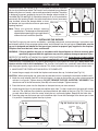
Fig. 4-1 below shows the critical dimensions of your firebox. The table below shows log set dimensions.
FIREPLACE REQUIREMENTS
This Real-Fyre® gas log set is to be installed only in
a fully vented, noncombustible fireplace with an open
damper. The chimney must be free of any obstructions.
The fireplace must be designed and approved to burn
wood. Your Real-Fyre® log set is designed to burn
with yellow, smoky flames. For this reason, it must be
adequately vented.
The fireplace must have a gas-supply line that has been
installed by a qualified technician in accordance with all
local codes. The gas-supply line must be ½" minimum
interior diameter. If the gas line to the fireplace is longer
than 20', a larger-diameter line may be necessary.
A fireplace screen must be in place when the system
is burning. Provisions for adequate combustion
air must be maintained. Unless other provisions for
combustion air are provided, the screen shall have
an opening(s) for introduction of combustion air.
Combustion air is adequate when all flames curl into
the fireplace and away from the screen. When a glass
fireplace enclosure (door) is used, leave the doors
fully open when the system is in operation.
Required Gas Pressure: The minimum inlet gassupply pressure for the purpose of input adjustment is
7" of water column (w.c.) for natural gas and 11" w.c.
for propane. The maximum inlet gas-supply pressure
is 10.5" w.c. for natural gas and 13" for propane.
Fig. 4-1
Fireplace Dimensions
Rear width
Height
Depth
Front
width opening
Note: It is recommended that complete firebox dimensions (front width,
back wall, and height) be obtained to ensure proper sizing.
Min. Fireplace Dimensions
Burner
size
Width
BTU
Depth Height
Front* Rear
NAT.
L.P.
12"
18"
16"
11"
18"
25k
25k
16/19"
25"
23"
11"
18"
39k
39k
18/20"
26"
24"
14"
18"
75k
50k
24"
30"
28"
14"
18"
90k
65k
30"
36"
34"
15"
18"
90k
65k
[36"]
42"
40"
16"
18"
120k
90k
[42"]
48"
46"
20 ½"
18"
150k
110k
[48"]
54"
52"
20 ½"
18"
150k
115k
[60"]
66"
64"
20 ½"
18"
150k
120k
* This required width allows for centering of the log set.
Add 4" to front width if the burner is to be installed with
a pilot kit.
Note: Rear width is at corresponding depth. Bracketed
sizes indicate non-certified burner systems.
Minimum Free Opening Area of Chimney Damper for Venting (sq. in.)
For Factory-Built Fireplaces *
Chimney
Height
15' (min.)
20'
30'
12"
16/19"
18/20"
24"
30"
36"
42"
48"
60"
16
14
13
25
22
20
47
43
38
57
51
46
57
51
46
75
68
61
94
85
76
94
85
76
94
85
76
* For Masonry-Built Fireplaces; add 4 sq. in. to amount shown.
REV 5 - 1407290845
4
L-A2-013
INSTALLATION
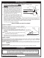
The damper clamp with hex bolt (Fig. 5-1) is provided as a means to prevent
full closure of the damper blade. The clamp is easily attached to most damper
blades with pliers or a wrench, and must be permanently installed. The clamp
is designed to prevent accidental closure of the damper when installed as
illustrated (Fig. 5-2 and Fig. 5-3). Should the clamp not fit, or fail to provide the
permanent vent opening listed in the table found above, have a permanent
stop installed, remove the damper blade, or have
the damper cut to provide the minimum permanent Set screw
opening required.
Note: These are minimum damper opening
specifications. The damper must be completely
opened when operating this gas appliance to
achieve the best ventilation possible.
Damper clamp
Fig. 5-1
Open
Closed
Fig. 5-2
Fig. 5-3
INSTALLING THE BURNER
The Real-Fyre gas log set must be installed by a qualified professional service technician. Instructions must
be followed carefully to ensure proper performance and full benefit from the gas log set. Check to be sure the
log set is designed and labeled for the type of gas (natural or propane gas) supplied to the fireplace.
Fireplace floor must be level, clean, and smooth.
WARNING: Failure to position the parts in accordance with these diagrams or failure to use only parts
specifically approved with this appliance may result in property damage or personal injury.
REFER TO THE PARTS LIST WHEN FOLLOWING THESE INSTRUCTIONS. If your burner is to be installed
with a pilot kit; carefully follow the instructions supplied with your pilot kit for specific gas connection.
The burner pan is supplied with an air mixer for propane gas or a fuel injector for natural gas. The air mixer / fuel
injector must be used in ALL installations. The air mixer / fuel injector has a precisely sized orifice to ensure
only the proper quantity of gas enters the burner. This allows maximum performance and gas conservation.
1. MAKE SURE THE FIREPLACE GAS SUPPLY IS TURNED OFF.
2. Locate the gas-supply stub inside the fireplace and remove the cap, if attached (see Fig. 5-4).
CAUTION: When removing the cap, make sure the stub does not turn, loosening the connection inside the wall.
3. Attach the small adapter (Item 9C) to the fuel injector / air mixer on the burner pan, using a pipe compound
resistant to all gases. Tighten securely. DO NOT REMOVE THE FUEL INJECTOR / AIR MIXER. Then
attach one end of the flex connector (Item 9B) to the small adapter. Tighten securely.
4. Place the burner system into the fireplace so the open burner pan faces outward.
5. Locate the grate (Item 13) and attach the stabilizer clips (Item 7) to the 2 outer bars of the grate with screws
and nuts. The stabilizer clips should be positioned towards the middle of the bars (Fig. 5-5). Place a clip
on each side of the bar, insert the screw, attach the nut, and loosely tighten. Repeat for the other side.
6. Place the grate over the burner pan so the stabilizer clips fit over the back edge of the burner pan to lock
it in position. Completely tighten the clips in place.
Fig. 5-4
Fig. 5-5 Stabilizer clips on grate
GRATE
STABILIZER
CLIPS
BACK
WALL OF
FIREPLACE
Gas line
cap
Gas supply
line stub
REV 5 - 1407290845
BURNER PAN
5
L-A2-013
INSTALLATION (cont.)
7. Center this assembly in the fireplace and place it
as far back in the fireplace as possible. Remove
the grate for the gas connection and granule/ember
placement.
Fig. 6-1 - Fireplace valve
8. Be sure gas to the fireplace is off. Attach the
large adapter (Item 9A) to the gas-supply stub
using a pipe compound resistant to all gases.
Tighten securely. Then attach the open end of the
flex connector to the large adapter. Tighten securely.
Ensure the pan rests level on the fireplace floor after
connection. Adjust the pan if necessary.
Flex
connector
Fuel injector
Burner
Pan
Large
adapter
Small
adapter
Gas
9. LEAK TEST: Use a long-necked butane lighter, or
supply line
lay a lighted match next to the burner pipe, and
carefully turn on the gas supply until the burner
ignites. Test at all connections for leaks using the
appropriate soapy water solution. If bubbles appear, a leak is present. Turn off the gas and tighten at all
connections. Repeat until no leaks are present. If a leak persists, turn off the gas supply and contact the
local gas company or dealer. NEVER USE A FLAME TO CHECK FOR LEAKS.
Turn off the gas supply prior to proceeding.
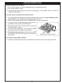
GRANULE, EMBER, AND GRATE PLACEMENT
GRANULE PLACEMENT
The granules supplied with the unit are specially selected for
use with either propane gas or natural gas. They maximize flame
distribution and reduce carbon buildup.
1. Fill the burner pan completely with the granules* (Item 11).
See Fig. 6-2. Avoid spilling the granules on the pilot kit (if
equipped).
*Note: Use only select sand for natural gas burners and
vermiculite for propane gas burners.
2. Slope the granules at the same angle as the burner pan. This is
important to ensure quiet lighting and even flame distribution.
Back wall
of fireplace
Place granules in
pan & slope to angle
of pan
Burner pan
Fig. 6-2 Granule placement
EMBER PLACEMENT
Sprinkle the glowing embers (Item 10) lightly and evenly over the entire surface of the granules. Break up
any clumps that may have developed during shipment. (For Charred series log sets, refer to OPTIONAL
CHARRED SERIES INSTALLATION section.)
Important: Do not add any additional embers to this log set. Any additional embers may cause unsafe
operation.
GRATE PLACEMENT
Replace the grate so that the stabilizer clips fit over the back edge of the pan, locking it in position.
LOG PLACEMENT
CAUTION: Burn hazard. Logs will remain hot for some time after use. You must maintain the
log layout as shown to ensure proper operation of your log set. If you need to
reposition any log to maintain the proper layout, use heat-resistant gloves or allow
logs adequate time to cool before handling.
Styles and sizes will vary depending upon the log set ordered. If the log set ordered includes placement
instructions; follow those instructions.
REV 5 - 1407290845
6
L-A2-013
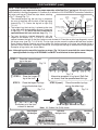
LOG PLACEMENT (cont.)
NOTE: LOGS SUPPLIED SEPARATELY.
Log placement is very important for the proper operation of the Real-Fyre® gas log set. Although you have
some flexibility in the log arrangement, it is necessary to follow the LOG PLACEMENT instructions carefully to
fully enjoy your log set. Follow the steps below, referring
Rear
bottom
to Fig. 7-1 through Fig. 7-5.
Front
Stabilizer
log
bottom
Back wall
clips
1. The second-longest log, the rear log, is placed on
log
Grate
of fireplace
the rear of the grate with the bark of the log facing
forward (Fig. 7-1). Center the log left to right (Fig.
7-5, #1).
Stabilizer clip
Glowing embers
fits over rear
(on top of granules)
2. The longest log, the front log, is placed on the front
edge of
burner pan
of the grate with the bark facing forward. Center left
Granules
to right (Fig. 7-2, #2). NOTE: Be sure to maintain a
Burner pan
space between the front and rear logs (Fig. 7-1).
Fig. 7-1
3. Top logs should be stacked diagonally, with the
largest at the bottom (Fig. 7-3, #3 & 4), and with
spaces between the logs so that the flames are not choked off. Place the smaller logs diagonally across
the larger ones (see Fig. 7-4, #5 & #6). The top logs may be moved to achieve desired flame pattern.
Some carbon buildup (sooting) may occur where the flames impinge on the logs and should not be a
concern unless excessive. If sooting is excessive, rearrange the top logs to reduce flame impingement.
Examples of log stacks are shown below.
Note: Although log styles may differ in pattern or shape ( Fig. 7-6), layout is essentially the same. Adequate
spacing between the logs is NECESSARY and MUST be maintained for best performance.
STEP 1.
Place the second-longest
log to the rear.
Fig. 7-2
1
2
Fig. 7-5
Alternative examples of log layout (Split Oak
set shown). Note the space between the logs.
STEP 2.
Place the longest
log at the front.
STEP 3.
Place the largest top logs
across the bottom logs.
STEP 3 (cont.)
Place the smaller top logs
across the other logs.
Fig. 7-4
Fig. 7-3
4
6
3
5
Knotholes go to the front
or back as desired.
(Note the gaps between the logs.)
Note: 24" Golden Oak (R-24) shown
Royal English
Oak Designer
Split Oak
Designer Plus
Woodland
Oak
Fig. 7-6 - Recommended log patterns
REV 5 - 1407290845
7
L-A2-013
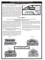
OPTIONAL CHARRED SERIES INSTALLATION
GLOWING EMBERS PLACEMENT
Note: Optional Charred Series log sets are supplied
with an ember screen (Fig. 8-1).
Fig. 8-1
Attach the ember screen to the burner by slipping
it onto the back edge (center left to right) with the
perforated section facing toward the back fireplace
wall (Fig. 8-1). Cover the surface of the ember
screen with the Glowing Embers (Fig. 8-2). For best
glowing performance, they should be applied evenly
and pulled slightly apart so the fibers are somewhat
loose. (It is not necessary to pile the entire bag of
the Glowing Embers. More Glowing Embers may be
added after completion of the entire installation).
Ember screen
(supplied with
optional Charred
Series log sets)
Fig. 8-2
LOG PLACEMENT
Log styles and sizes will vary depending upon the Charred Series log set ordered.
CHARRED SPLIT (CHS) layout shown.
Place the long bottom rear log (Log #2) on the back Place the small top charred logs (Logs #5 & 6) so
of the grate with the flat featureless side facing the they rest over the charred sections of the front bottom
rear of the fireplace. The two sections of the front log sections (Logs # 1A & 1B) and on the two curved
log (Logs #1A & 1B) are placed on the front of the logs (Logs #3 & 4) (Fig. 8-5).
grate with the charred sections facing each other Finally, place the curved top charred log (Log #7) to
and approximately 1 inch apart at the top (Fig. 8-3). rest on the two top logs at rear, but not encroaching
Slide the logs to the front of the grate.
into the space between rear and front logs (Fig. 8-6).
Note: Be sure to maintain a space between the
front and rear logs (Fig. 8-3).
Note: The additional top log (Log #7) is not available
with 18" log sets.
Place the two curved logs (Logs #3 & 4) so that one
end rests on each front log section (Logs #1A & 1B)
and the other end rests on the rear log (Log #2).
The charred sections should be over the opening
between the front and rear logs (Fig. 8-4).
Fig. 8-3
Fig. 8-4
LOG #2
LO
#4
G
G
#3
LO
LOG #1A
LOG #1B
MAINTAIN A SPACE IN THE CENTER OF
THE LOGS AT ALL TIMES
Fig. 8-5
Fig. 8-6
Log #7
G
LO
G
REV 5 - 1407290845
#5
#6
LO
8
L-A2-013
LIGHTING INSTRUCTIONS
Before operating your gas log set:
1. Be sure your fireplace is free from flammable liquids or combustible materials.
2. Be sure your damper is open.
3. Smell all around the gas log set for the odor of escaping gas. IF YOU SMELL GAS, FOLLOW THE
INSTRUCTIONS ON P. 1.
If your gas log set is operated by the fireplace valve:
1. Lay a lighted long-stem match on the surface of the embers near the gas inlet (do not hold the match
in your hand) or use a lighted long-necked butane lighter (Fig. 9-1).
2. Slowly turn the fireplace remote valve to the ON position. Your log set should light.
3. If the log set does not light before the match goes out,
immediately turn the valve to the OFF position.
4. Wait approximately five (5) minutes to clear out any gas,
and repeat steps 1-3 above.
5. If your log set fails to light again, turn the valve to the OFF
position and contact your dealer or gas supplier.
6. To extinguish your gas log set, turn the valve to the OFF
position. Be sure the valve is turned fully off to avoid any
gas leakage.
Fig. 9-1
Apply match - then turn on gas
If your burner is operated by a pilot kit:
1. Carefully follow the lighting instructions supplied with your pilot kit for the steps to ignite the burner.
REV 5 - 1407290845
9
L-A2-013
MAINTENANCE & SERVICE
Maintenance
Once installed and operating properly, your Real-Fyre® gas log set will require regular maintenance.
You should inspect your log set and controls (where installed) for the following:
1. Excessive sooting - Some sooting of your log set is normal, adding to the appearance of burned
wood. If excessive sooting accumulates, clean the logs using any of the following options:
Option 1. Spray the logs with clean water when they are being burned and hot.
The soot will lift off and burn off.
Option 2. Brush the soot off with a stiff brush when the logs are cold.
Do not use water or soot cleaners at the same time as brushing the soot off.
2. Moisture may cause the granules and Glowing Embers in your burner pan to settle. To improve the burn,
follow these tips.
a. Settling of sand (or vermiculite) - Using a screwdriver or flat-blade knife, carefully stir the granules,
loosening the material. Clear up any spills.
b. Embers - Break up any clumps that may have formed, then redistribute the embers on the granules.
3. Debris around the control (where used) - Inspect control and pilot to be sure it is free of dirt or debris.
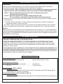
Service
While some minor service conditions may be handled by the owner of the log set, it is recommended that a
qualified professional service technician be called to maintain and service the gas log set and any installed
control system. The TROUBLESHOOTING section of these instructions serves as a guide for ensuring optimum
performance of your gas log set.
OPTIONAL CONTROLS
THIS UNIT COMES WITHOUT A VALVE INSTALLED.
IT MAY BE CONNECTED DIRECTLY TO AND OPERATED BY YOUR FIREPLACE VALVE.
Alternatively, your Real-Fyre® gas log set may be operated using a number of optional Peterson control
systems (see below). Peterson control systems are engineered to provide convenient, safe, and reliable
operation of your gas log set.
For safe operation, proper performance, and to comply with safety standards and certifications, use
only Robert H. Peterson Company control systems, parts, and accessories with your Real-Fyre® log set.
If you have purchased a valve separately, unpack your Peterson control system and check the PARTS LIST
provided with your control to be sure all parts are included.
Peterson Control Systems
Manual On/Off Systems
AV-17 (knob) or AV-18 (rod handle)
................
Manual Safety Pilot Systems
SPK-20 (knob) or SPK-21 (rod handle) ..........
SPK-26 ...........................................................
Manual On/Off, match lit, no pilot
Standard Pilot
Low-Profile Valve
Remote Systems (APK-11, EPK-01)
Available Accessories
Toggle Switch, WS-1 Wall switch, WS-2 Wall timer, WCS-1 Wood Chip switch, RR-1A Remote, RR-2A,
Deluxe Remote, PC-105 Pine Cone Remote.
Variable Remote System (APK-150, APK-15, APK-17)
Available Accessories
WS-3 Wall switch, VR-1A Variable Flame-Height Remote, VR-2A Deluxe Variable Flame-Height Remote.
REV 5 - 1407290845
10
L-A2-013
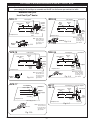
OPTIONAL PETERSON VALVES & SAFETY PILOT KITS*
Note: For all valves and safety pilot kits shown on this page, carefully follow the instructions supplied with
your safety pilot kit for steps to assemble and install it on the burner pan and test for leaks.
*Available from your
local Real-Fyre® dealer
APK-11
SPK-20
Fuel injector
Main burner
pipe
Burner
pan
Fuel injector
Main
burner
pipe
Hearth
adapter
Connector
Burner
pan
Gassupply
line
Connector
APK-11
remoteready Adapter
valve
Fireplace floor
SPK
valve
Fireplace floor
Note: Heat shield is not
shown, but must
be in place when
operating your
glass burner.
APK-11
Valve
Gassupply
line
Hearth
adapter
Note: Heat shield is not
shown, but must
be in place when
operating your
glass burner.
SPK-20
Fig. 11-4
Fig. 11-1
APK-15
SPK-26
Fuel injector
Main burner
pipe
Burner
pan
Connector
Fuel injector
Connector
Burner
pan
Main burner
pipe
Adapter
Fireplace floor
APK-15
Valve
Fig.
APK-17
Gassupply
line
Hearth
adapter
APK-15
remote
safety
valve
Adapter
Note: Heat shield is not
shown, but must
be in place when
operating your
glass burner.
11-2
INJECTOR
Fuel FUEL
injector
BURNER
Burner PAN
pan
SPK-26 Hearth
safety adapter
valve
Fireplace floor
SPK-26
Valve
Fig. 11-5
AV-17
AV-18
Connector
CONNECTOR
TUBE
Fuel injector
Main burner
pipe
Adapter
GAS SUPPLY
LINE
Gas-supply
line
ELBOW
Note: Heat shield is not
shown, but must
be in place when
operating your
glass burner.
Burner
pan
Flared adapter
Connector
Gassupply
line
FRONT FLAME BOOSTER
SPKvalve
VALVE
APK
ON/OFF
valve
Fireplace floor
APK-17(M)(P) valve
APK valve
Fireplace floor
Hearth
adapter
Fig. 11-7
Note: Heat shield is not
shown, but must
be in place when
operating your
glass burner.
Fig. 11-3
REV 5 - 1407290845
11
L-A2-013
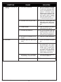
TROUBLESHOOTING YOUR GAS LOG SET
SYMPTOM
1. Excessive smoking and
sooting
2. Low flame
REV 5 - 1407290845
CAUSE
SOLUTION
A. Poor draft or downdraft
A. Check for chimney blockage.
Be sure chimney is at least
3' taller than anything within
10' of it in all directions. If not,
consult a chimney sweep.
Chimney cap or fan may help.
Under severe conditions, you
may need to open a window
near the fireplace about 1" to
2" when burning the log set.
B. Improper burner for gas used
B. Use only a natural-gas set
with natural gas. Use only a
propane-gas set with propane
gas.
C. Damper closed
C. Open the damper fully when
operating the gas log set.
D. Improper log placement
D. Be sure the bottom logs are
spaced at least 3" apart. Top
logs should be placed to
minimize flame impingement.
E. Air mixer on propane set is
closed
E. Open the air mixer completely.
A. Incorrect log set for type of gas
used
A. Consult your dealer for proper
set.
B. Insufficient gas supply
B. Other gas appliances may
be competing for gas supply.
Consult installer or plumber.
Orifice size is based upon
7" w.c. pressure for natural
gas and 11" w.c. pressure for
propane gas. Plumbing must
supply adequate pressure.
C. Blockage or kink in connector
kit, plumbing, or burner orifice
C. Clean out blockage. If connector
kit is kinked, replace it.
D. Valve not fully open
D. Open valve fully.
12
L-A2-013
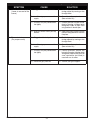
TROUBLESHOOTING YOUR GAS LOG SET (Continued)
SYMPTOM
3. Uneven flame distribution.
(Lower at one end of the
burner)
4. Flame at air mixer
(For propane units)
REV 5 - 1407290845
CAUSE
SOLUTION
A. Clogged or blocked portholes
A. Portholes can be cleared of
foreign object by running a wire
through them.
B. Insufficient gas pressure and/or
supply
B. Consult installer or plumber.
(See solution 2b.)
C. Granules may be packed down
too tightly
C. Loosen granules around burner
pipe by running a kitchen knife
along both sides or pipe. Even
out granules in burner pan.
D. Auxiliary shutoff valve partially
closed
D. Open valve fully. Usually, you will
find this along the wall 3' from the
fireplace.
A. Clogged or blocked portholes
A. Portholes can be cleared of
foreign objects by running a wire
through them.
B. Insufficient gas pressure and/or
supply
B. Consult installer or plumber.
(See solution 2b.)
C. Granules may be packed down
too tightly
C. Loosen granules around the
burner by running a kitchen knife
along both sides of the pipe. Be
sure vermiculite (not sand) is
used with an air mixer.
D. Excessive gas pressure
D. Contact your gas supplier.
13
L-A2-013
WARRANTY
PETERSON VENTED DECORATIVE GAS APPLIANCE
LIMITED WARRANTY
Robert H. Peterson Co. ("RHP") warrants your Real Fyre® vented decorative gas appliance to be free from defects in material and
workmanship.
Peterson vented ceramic refractory gas logs are warranted for as long as you own them (lifetime).
Peterson vented burner assemblies are WARRANTED for TEN (10) YEARS. Peterson vented outdoor stainless-steel burner
assemblies are warranted for FIVE (5) YEARS.
Peterson glass, gems, nuggets, and fiber-ceramic blend gas logs are warranted for FIVE (5) YEARS.
SPK-26 controls are warranted for THREE (3) YEARS.
APK-17 controls (including -17 valve) are warranted for TWO (2) YEARS.
All other Peterson valves, pilots, and controls are warranted for ONE (1) YEAR (excluding batteries).
A COPY OF YOUR SALES SLIP FOR PROOF OF PURCHASE IS REQUIRED
This warranty applies to the original purchaser for products which are installed in the United States or Canada and which are operated and maintained
as intended for single family residential usage. This warranty is valid only with proof of purchase, shall commence on the date of purchase, and shall
terminate (both as to original and any replacement products) on the anniversary date of the original purchase of the product stated on the above schedules.
This warranty covers defects in material and workmanship. This warranty does not cover parts which become defective as a result of negligence, misuse,
use not in compliance with the Owner’s Manual/Installation Instructions, accidental damage, improper handling, improper storage, improper installation,
lack of required routine maintenance (as specified in the Owner’s Manual/Installation Instructions), electrical damage, local gas impurities or failure to
protect against combustibles. Product must be installed (and gas must be connected) as specified in the Owner’s Manual/Installation Instructions by
a qualified professional installer. Modifications to products which are not specifically authorized will void this warranty. Accessories, parts, valves,
remotes, etc. when used must be Peterson products or this warranty is void. Warrantied items will be repaired or replaced at Peterson’s sole discretion.
This warranty does not apply to rust, corrosion, oxidation, or discoloration unless the affected part becomes inoperable.
This warranty does not cover labor or labor related charges, except as provided by separate specific written programs from the Peterson Co. All repair
work must be performed by a qualified professional service person and requires prior approval of Peterson.
Peterson may require the defective product or part to be returned to the factory to determine the cause of failure. Peterson will pay freight charges if
the product or part is determined to be defective. This warranty does not cover breakage in shipment from our (Independent) distributor to its customer
if the damage is determined to have occurred during that shipment.
This warranty specifically excludes liability for indirect, incidental, or consequential damages. Some states and provinces do not allow the exclusion
or limitation of incidental or consequential damages, so the above exclusion may not apply to you. This warranty gives you specified legal rights, and
you may have other rights that vary from state to state or province.
For additional information regarding this warranty, or to place a warranty claim, contact the R. H. Peterson dealer where the product was purchased.
TO REGISTER YOUR PRODUCT ONLINE GO TO: WWW.RHPETERSON.COM,
AND CLICK ON PRODUCT REGISTRATION. THANK YOU FOR YOUR PURCHASE.
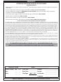
Quality Check
Burner Orifices Nat.
Date:_________________
L.P.
Leak Test: ___________ Model#:
___________________
Main:
____ ____
Burn Test: ___________ Serial#:
___________________
Other:
____ ____
Gas Type:
Nat. / L.P.
Air Shutter: ___________________
Inspector:
___________________
Robert H. Peterson Co. • 14724 East Proctor Avenue • City of Industry, CA 91746
14