1
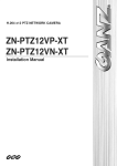
NM-IP100
Installation Guide
INFORMATION TO USER CAUTION RISK OF ELECTRIC SHOCK, DO NOT OPEN !
CAUTION: TO REDUCE THE RISK OF ELECTRIC SHOCK, DO NOT REMOVE COVER (OR BACK). NO USER SERVICEABLE PARTS INSIDE. REFER SERVICING TO QUALIFIED SEERIVCE PERSONEL. !
This symbol is intended to alert the user to the presence of un‐insulated “dangerous voltage” within the product’s enclosure that may be of sufficient magnitude to constitute a risk of electric shock to persons. This symbol is intended to alert the user to the presence of important operating and maintenance (servicing) instructions in the literature accompanying the appliance. NM‐IP100 Table of Contents
1. FEATURES ............................................................................................................... 4
2. PACKAGE CONTENTS .............................................................................................. 5
3. PART NAMES .......................................................................................................... 6
4. INSTALLATION ........................................................................................................ 7
4.1. Installation Template ......................................................................................................... 8
4.2. Manual adjustment for 3‐axis movements ........................................................................ 8
4.3. Lens Focus Adjustment ...................................................................................................... 9
4.4. Setting the Image Attribute................................................................................................ 9
5. CONNECTIONS ...................................................................................................... 10
6. CONFIGURATION .................................................................................................. 11
6.1.Set up network environment ............................................................................................ 11
6.2.View video on web page ................................................................................................... 11
6.2.1.View video using IPAdmin Tool.................................................................................. 11
6.2.2.View video using IP address ....................................................................................... 14
6.3. Reset................................................................................................................................. 14
6.4. Factory Default................................................................................................................. 14
APPENDIX (A): SPECIFICATIONS ................................................................................ 15
Summary ................................................................................................................................. 15
Electrical Characteristics ......................................................................................................... 16
Environment Condition ........................................................................................................... 16
VCA (Video Content Analysis) ................................................................................................. 16
APPENDIX (B): DIMENSIONS..................................................................................... 17
REVISION HISTORY ................................................................................................... 18
3 NM‐IP100 1. FEATURES
Camera •
•
•
Indoor Fixed Mini Dome IP Camera High Quality Compression in real time streaming 1/4” VGA CMOS Streaming •
•
•
•
Dual streaming mode (such as different codec/resolution/bit rate and so on.) De‐interlacing on DSP Burnt‐in text supported Unicast/Multicast supported Video/Audio •
•
•
•
Video compression: H.264/MPEG4/MJPEG (30FPS@D1) Audio compression: G.711(µLaw, aLaw)/PCM Video Motion Detection supported 2‐way mono audio supported Network •
•
RTSP/ HTTP protocol supported 10/100 Base‐T Ethernet Additional Features •
•
•
Built‐in Video Content Analysis OSD supported SDK (Software Development Kit) provided VCA (Video Content Analysis) •
•
VCA Presence (Included as basic) VCA Surveillance (Optional) 4 NM‐IP100 2. PACKAGE CONTENTS
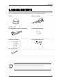
Unpack carefully and handle the equipment with care. The packaging contains: Camera DC power adaptor Extension cable (for LAN, power connector, and audio ) Quick Installation Guide Installation Template Screws and Anchor block Hex wrench driver i
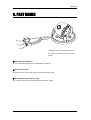
The above contents are subject to change without prior notice. Note 5 NM‐IP100 3. PART NAMES
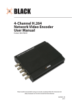
① ② ③ * Models herein and their appearance are subject to change without any prior notice. ①LAN Connector (Ethernet) This is a RJ45 LAN connector for 10/100 Base‐T Ethernet. ② Audio in/ out Cable Thecamera has a mono audio input and a mono audio output. ③Power Adaptor Connector (DC 12V) The camera requires a DC 12V 1A adapter for power supply. 6 NM‐IP100 4. INSTALLATION
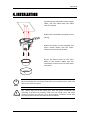
1) Connect the LAN cable, power supply cable, and the video loop out cable with the camera. 2) Place the installation template on the ceiling. 3) Drill two holes on the template and insert anchor blocks into the holes. Fasten the camera with screws. 4) Put the dome cover on the main body of the camera. Make sure the main body and the cover fit each other into place. i
Note When assembling the main body of the camera and its dome cover, make sure they fit each other into place. The camera may fall off the ceiling even after the proper installation and mounting. To prevent any accident, make sure the ceiling is firm and stable enough to support the camera. If any reinforcement is needed, consult with Caution your safety personnel and proceed with the installation. !
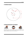
7 NM‐IP100 4.1. Installation Template
2‐Ø6
Ø125
Ø30
68.5 4.2. Manual adjustment for 3-axis movements
After installation, make a manual adjustment on the inner liner. Perform 3‐axis movements manually by turning the inner liner to different directions as above, and check if it moves properly. After adjustment, fasten the screw of the rotation axis. 8 NM‐IP100 4.3. Lens Focus Adjustment
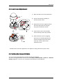
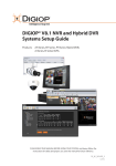
1) Open the dome cover from the device. A 2) Uncover the latch(C) carefully to remove the lens cover. 3) Rotate the lens focus ring(D) to adjust the focus and fasten the screw(E) using the included hex wrench. 4) Push the lens cover to the module until the latch(C) clicks into position. C D 5) Attach the dome cover by aligning protrusion on the body (B) with the inverted triangle mark of the dome cover (A). Turn the dome cover clockwise to lock. E * Models herein and their appearance are subject to change without any prior notice. 4.4. Setting the Image Attribute
You can set the image attribute of camera through the webpage. The menu of image attribute can be seen under Setup > Video & Audio > Video‐in > Attribute Setting. Brightness, contrast, hue, saturation and sharpness can be adjusted. 9 NM‐IP100 5. CONNECTIONS
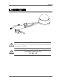
LAN DC 12V !
Caution Make sure the polarity is correct. Incorrect connection may cause malfunction or damage to the IP device. !
Power Adaptor Connector (DC 12V) Caution 10 NM‐IP100 6. CONFIGURATION
6.1.Set up network environment
The default IP address of your IP device is 192.168.XXX.XXX. You can find the available IP address from the MAC address of your device. Please make sure the device and your PC are on the same network segment before running the installation. If the network segment between your PC and the device is different, change your PC’s settings as below. IP address : 192.168.xxx.xxx Subnet mask: 255.255.0.0 6.2.View video on web page
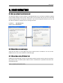
View the live video on a web page using your IP device and its IP address. You can use the IPAdminTool or enter the IP address on the web page. 6.2.1.View video using IPAdmin Tool
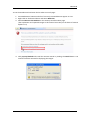
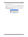
IPAdminTool automatically searches all activated network encoders and IP cameras and shows the product name, IP address, MAC address and etc. IPAdminTool is provided with SDK at the following SDK path. {SDK root}\BIN\TOOLS\AdminTool\ 11 NM‐IP100 To use the IPAdminTool and view the live video on a web page: 1. Start IPAdminTool. Names and info of currently activated devices appear as a list. 2. Right‐click on the desired device and select Web view. 3. Select Continue to this website on the Security Certificate Alert page. (The explanation and captured images at this manual are mainly on the basis of Internet Explorer 7.0) 4. Click pop‐up blocked and install the ActiveX control by clicking the Install button. You need to install the ActiveX for displaying the images. 12 NM‐IP100 5. Wait for a few seconds while the web page loads. Then the live video is displayed on the main page of the web browser. 6. If the live video is not displayed and “Can not Create XMLDOMDocument Install MSXML4.0” message is shown as below, please download and Install from the link below. http://www.microsoft.com/downloads/details.aspx?familyid=3144B72B‐B4F2‐46DA‐
B4B6‐C5D7485F2B42&displaylang=en (VCA Library requires MS XML 4.0 library which is an xml parser made by Microsoft.) 13 NM‐IP100 6.2.2.View video using IP address
View the live video on a web page using your IP device and its IP address. To have the correct IP address ready and use it on a web page: 1. Convert a MAC address to an IP address or check the IP address on the IPAdminTool. (The MAC address is attached on the side or bottom of the device.) MAC address = 00‐13‐23‐01‐14‐B1 → IP address = 192.168.20.177
the Hexadecimal number to Decimal number. 2. Open a web browser and enter the IP address of the device. 3. Click Continue to this website on the Security Certificate Alert page. 4. Click pop‐up blocked and install the ActiveX control. You need to install the ActiveX for displaying the images. 5. Wait for a few seconds while the web page loads. The live video is displayed. 6.3. Reset
Hardware Reset is NOT supported. (Software Reset is available.) To perform the Software Reset, please refer to the “HTTP API Manual” provided for your encoder model. 6.4. Factory Default
Hardware Factory Reset is NOT supported. (Software Factory Reset is available.) To perform the Software Factory Reset, please refer to the “HTTP API Manual” provided for your encoder model. 14 NM‐IP100 APPENDIX (A): SPECIFICATIONS
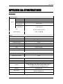
Summary
Camera Module Image Sensor Effective Pixels Scanning system CMOS Horizontal Resolution Min. Illumination 1/4” VGA CMOS 640 x 480 Progressive Scan 550 TV Lines 3 Lux Color 0.1 Lux DSS On Focal Length 3.6 mm, F.# 2.0, Board type, Lens for Security Camera Lens Shutter Speed 1/60 ~ 1/100,000 Day & Night Not Supported Compression Format H.264, MPEG‐4, MJPEG Selectable per Stream Number of Streams Dual Stream, Configurable Resolution D1*1, 4CIF*1, VGA, CIF, QCIF Compression FPS 30 fps Deinterlacing Supported (DSP) Motion Detection Supported OSD Supported (DSP) Burnt‐in Text (Digital) Supported (DSP) Output Not Available Input/output 1/1 channel Compression Format G.711 Video Audio Function Digital Input/output Not Supported Network 10/100 Base‐T Power over Ethernet Not Available Protocol TCP/IP, UDP/IP, HTTP, RTSP, RTCP, RTP/UDP, RTP/TCP, SNTP, mDNS, UPnP, SMTP, SOCK, IGMP, DHCP, FTP, DDNS, SSL v2/v3, IEEE 802.1X, SSH Material Polycarbonate Dimensions Housing: 124(D) x 100(H) mm, Dome: 100.0(Ф) mm Color *1. These image sizes are scaled up resolutions. Black 15 NM‐IP100 Electrical Characteristics
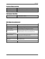
Video Output Audio Input Audio Output Power Source(Approx) 1Vp‐p, 75Ω Linein, 1.43Vp‐p(Min 1.35Vp‐p, max 1.49 Vp‐p), 39 KΩ Lineout, 46mW Power, 16 Ω 12 V DC 290 mA Environment Condition
Operating Temperature 0 ˚C ~ 50 ˚C (32˚F ~ 122 ˚F) Operating Humidity Up to 85% RH VCA (Video Content Analysis)
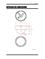
VCA Presence (Included as Standard) High Performance Advanced Tracking Algorithm, Low False Alarm Rate Easy to Use Intuitive Web Browser Interface Detection Zones Multi‐segment Polygons and Lines On‐screen Display Real‐time Display of Tracking Data and Events Stream or Analog video out Burnt‐in Annotation (※Analog video out support can vary depending on the device model and hardware version and the firmware version) VCA Surveillance (Optional) Detection Behavior Camera Tampering, Direction, Stopping, Loitering, Entering, Exiting, Appear, and Disappear Filters 3D Behavior Perspective Corrected Size and Speed Filters Statistics Counting Functions and Other Statistics Meta Data Binary XML Format Image Stabilization (Optional) Electronic Stabilization Removes Camera Sway 16 NM‐IP100 APPENDIX (B): DIMENSIONS
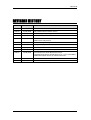
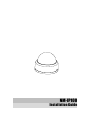
Ø124 40 100 50 R50 (Unit: mm) 17 NM‐IP100 REVISION HISTORY
MAN# DATE(M/D/Y) Comments 01A.00 07/23/2009 Created. 02A.00 07/04/2009 FW 1.00.07 official release version 02A.01 08/06/2009 Added images to package contents 02A.02 08/24/2009 Added the requirement of VCA : MSXML4.0 02A.03 09/03/2009 Added Power Consumption Added Focus Adjustment 02A.04 09/25/2009 Added Setting the Image Attribute 02A.05 09/29/2009 Changed VCA specification 03A.00 10/13/2009 FW 1.02.02 official release version 03A.01 10/15/2009 Changed the Reset and Factory default description 03A.02 12/09/2009 Corrected Errata about Network Protocol Changed Image Sensor specification (1/3”‐> 1/4” VGA CMOS) Added Description about up‐scaled resolutions 03B.00 01/19/2010 Added Shutter Speed and reviewed 03B.01 02/25/2010 Modified for end users 18