1
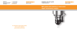
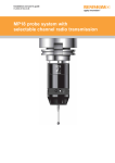
Installation and user’s guide
H-2000-5015-05-N
MI 8 interface unit
© 1995 Renishaw. All rights reserved.
Disclaimer
Renishaw® is a registered trademark of
Renishaw plc.
Considerable effort has been made to
ensure that the contents of this document
are free from inaccuracies and omissions.
However, Renishaw makes no warranties
with respect to the contents of this document
and specifically disclaims any implied
warranties. Renishaw reserves the right to
make changes to this document and to the
product described herein without obligation
to notify any person of such changes.
This document may not be copied or
reproduced in whole or in part, or transferred
to any other media or language, by any
means, without the prior written permission
of Renishaw.
The publication of material within this
document does not imply freedom from
the patent rights of Renishaw plc.
Trademarks
All brand names and product names used in
this document are trade names, service marks,
trademarks, or registered trademarks of their
respective owners.
Renishaw part no: H-2000-5015-05-N
Issued: 03.2003
Installation and user's guide
MI 8 interface unit
S2
FCC DECLARATION (USA)
FCC Section 15.19
This device complies with Part 15 of the FCC rules.
Operation is subject to the following two conditions:
1. This device may not cause harmfull interference.
2. This device must accept any interference received,
including interference that may cause undesired
operation.
FCC Section 15.105
This equipment has been tested and found to comply
with the limits for a Class A digital device, pursuant to
Part 15 of the FCC rules. These limits are designed to
provide reasonable protection against harmful
interference when the equipment is operated in a
commercial environment.
This equipment generates, uses, and can radiate radio
frequency energy and, if not installed and used in
accordance with the instruction manual, may cause
harmful interference to radio communications.
Operation of this equipment in a residential area is likely
to cause harmful interference, in which case you will be
required to correct the interference at your own expense.
FCC Section 15.21
The user is cautioned that any changes or modifications
not expressly approved by Renishaw plc, or authorised
representative could void the user's authority to operate
the equipment.
FCC Section 15.27
The user is also cautioned that any peripheral device
installed with this equipment such as a computer, must
be connected with a high-quality shielded cable to insure
compliance with FCC limits.
GB
WARNINGS
Information for the user
Replace blown fuses with new components of
the same type. Refer to the SAFETY section of
the relevant product documentation.
Remove power before performing any
maintenance operations.
Refer to the machine supplier's operating
instructions.
Information for the machine supplier
It is the machine supplier's responsibility to ensure
that the user is made aware of any hazards involved
in operation, including those mentioned in Renishaw
product documentation, and to ensure that adequate
guards and safety interlocks are provided.
Under certain circumstances the probe signal may
falsely indicate a probe seated condition. Do not rely
on probe signals to stop machine movement.
D
ACHTUNG
Informationen für den Benutzer
Durchgebrannte Sicherungen müssen mit
gleichwertigen ersetzt werden. Beziehen Sie
sich bitte auf die SICHERHEITSHINWEISE in
der Produktdokumentation.
Vor Wartungsarbeiten muss die Stromversorgung
getrennt werden.
Beziehen Sie sich auf die Wartungsanleitungen des
Lieferanten.
Informationen für den Maschinenlieferanten
Es obliegt dem Maschinenlieferanten, den Anwender
über alle Gefahren, die sich aus dem Betrieb der
Ausrüstung, einschließlich der, die
in der Renishaw Produktdokumentation erwähnt
sind, zu unterrichten und zu versichern, dass
ausreichende Sicherheitsvorrichtungen und
Verriegelungen eingebaut sind.
Unter gewissen Umständen könnte das Messtaster
Fehlsignale melden (Ausgelenkt). Verlassen sie sich
nicht auf das Messtastersignal um die Maschine zu
stoppen.
DK
ADVARSLER
Oplysninger til brugeren
Udskift sikringer, der er sprunget, med nye
komponenter af samme type. Se i afsnittet
SIKKERHED (SAFETY) i produktdokumentationen.
Afbryd strømforsyningen, før der foretages
vedligeholdelse.
Se maskinleverandørens brugervejledning.
Oplysninger til maskinleverandøren
Det er maskinleverandørens ansvar at sikre, at
brugeren er bekendt med eventuelle risici i
forbindelse med driften, herunder de risici, som
er nævnt i Renishaws produktdokumentation,
og at sikre, at der er tilstrækkelig afskærmning
og sikkerhedsblokeringer.
Under visse omstændigheder kan probesignalet
ved en fejl angive, at proben står stille. Stol ikke på,
at probesignaler stopper maskinens bevægelse.
S3
S4
E
ADVERTANCIAS
Información para el usuario
Sustituir los fusibles fundidos con componentes
nuevos del mismo tipo.Remitirse a la sección titulada
SEGURIDAD (SAFETY) en la documentación sobre el
producto.
Quitar la corriente antes de emprender cualquier
operación de mantenimiento.
Remitirse a las instrucciones de manejo del
proveedor de la máquina.
Información para el proveedor de la máquina
Corresponde al proveedor de la máquina asegurar
que el usuario esté consciente de cualquier peligro
que implica el manejo de la máquina, incluyendo los
que se mencionan en
la documentación sobre los productos
Renishaw y le corresponde también asegurarse de
proporcionar dispositivos de protección y
dispositivos de bloqueo de seguridad adecuados.
Bajo determinadas circunstancias la señal de la sonda
puede indicar erroneamente que la sonda está
asentada.No fiarse de las señales de la sonda para
parar el movimiento de la máquina.
F
AVERTISSEMENTS
Informations à l’attention de l’utilisateur
Remplacer les fusibles grillés par des composants
neufs du même type. Consulter la section SECURITE
de votre documentation.
Mettre la machine hors tension avant d’entreprendre
toute opération de maintenance.
Consulter le mode d’emploi du fournisseur de la
machine.
Informations à l’attention du fournisseur de la
machine
Il incombe au fournisseur de la machine d’assurer
que l’utilisateur prenne connaissance des dangers
d’exploitation, y compris ceux décrits dans la
documentation du produit Renishaw, et d’assurer que
des protections et verrouillages de sûreté adéquats
soient prévus.
Dans certains cas, il est possible que le signal issu du
capteur indique à tort que celui-ci est hors matière.
Ne pas se fier aux signaux du capteur qui ne
garantissent pas toujours l’arrêt de la machine.
FIN
TURVALLISUUS
Käyttäjälle tarkoitettuja tietoja
Korvaa palaneet sulakkeet samantyyppisillä uusilla
sulakkeilla. Lue tuoteselosteen TURVALLISUUTTA
(SAFETY) koskeva osa.
Kytke virta pois päältä ennen huoltotoimenpiteitä.
Katso koneen toimittajan käyttöhjeita.
Tietoja koneen toimittajalle
Koneen toimittajan vastuulla on, että käyttäjä on
saanut tiedon mahdollisista käyttöön liittyvistä
vaaroista, mukaan lukien Renishaw’n
tuoteselosteessa mainitut vaarat. Konetoimittajan
tulee myös varmistaa, että suojukset ja
turvalukitukset ovat riittävät.
Tietyissä olosuhteissa anturilta tuleva siganaali
saattaa osoittaa virheellisesti, että anturi on
paikallaan. Älä luota anturin signaaleihin koneen
liikkeen pysäyttämiseksi.
GR
S5
S6
I
SICUREZZA
Informazioni per l’utente
Per essere in condizioni di sicurezza continuativa
è indispensabile che il fusibile sia sostituito con
un componente del tipo corretto e di uguale valore
nominale. Consultare la sezione SICUREZZA nella
documentazione dello specifico prodotto.
Prima di effettuare qualsiasi intervento di
manutenzione, isolare dall’alimentazione di rete.
Consultare le istruzioni d’uso del fabbricante
della macchina.
Informazioni per il fabbricante della macchina
Il fornitore della macchina ha la responsabilità
di avvertire l’utente dei pericoli inerenti al
funzionamento della stessa, compresi quelli
riportati nelle istruzioni della Renishaw, e di
fornire ripari di sicurezza e interruttori di
esclusione adeguati.
È possibile che in certe situazioni venga
erroneamente prodotto un segnale che indica
che la sonda è in posizione. Non fare affidamento
sugli impulsi trasmessi dalla sonda per arrestare
la macchina.
NL
WAARSCHUWINGEN
Informatie voor de Gebruiker
Doorgeslagen zekeringen met nieuwe componenten
van hetzelfde type vervangen.U wordt verwezen naar
het hoofdstuk VEILIGHEID (SAFETY) in de
produktendocumentatie.
Voordat u enig onderhoud verricht dient u de stroom
uit te schakelen.
Raadpleeg de bedieningsinstructies van de
machineleverancier.
Informatie voor de Machineleverancier
De leverancier van de machine is ervoor
verantwoordelijk dat de gebruiker op de hoogte wordt
gesteld van de risico’s die verbonden zijn aan
bediening, waaronder de risico’s die vermeld worden
in de produktendocumentatie van Renishaw. De
leverancier dient er tevens voor te zorgen dat de
machine is voorzien van voldoende beveiligingen en
veiligheidsgrendelinrichtingen.
Onder bepaalde omstandigheden kan het
tastersignaal een onjuiste tastertoestand
aangeven.Vertrouw niet op de tastersignalen
voor het stoppen van de machinebeweging.
P
AVISOS
Informações para o Utilizador
Substituir fusíveis danificados por novos componentes
do mesmo tipo. Consultar a
seção SEGURANÇA (SAFETY) na documentação
do produto.produto.
Desligar a alimentação de energia antes de efetuar
qualquer operação de manutenção.
Consultar as instruções de funcionamento do fabricante
da máquina.
Informações para o Fornecedor da Máquina
É responsabilidade do fabricante da máquina assegurar
que o usuário esteja consciente de quaisquer perigos
envolvidos na operação, incluindo os mencionados na
documentação dos produtos Renishaw e assegurar que
são fornecidas proteções e bloqueios de segurança
adequados.
Em determinadas circunstâncias, o sinal do apalpador
pode indicar incorretamente uma condição de toque.
Não confie nos sinais do apalpador para parar o
movimento da
máquina.
SW
VARNING
Information för användaren
Byt ut smälta säkringar med nya av samma typ.
Se avsnittet SÄKERHET (SAFETY) i
produktdokumentationen.
Koppla bort strömmen innan underhåll utförs.
Se maskintillverkarens bruksanvisning.
Information för maskinleverantören
Maskinleverantören ansvarar för att användaren
informeras om de risker som drift innebär,
inklusive de som nämns i Renishaws
produktdokumentation, samt att tillräckligt goda
skydd och säkerhetsförreglingar tillhandahålls.
Under vissa omständigheter kan sondens signal
falskt ange att en sond är monterad.Lita ej på
sondsignaler för att stoppa maskinens rörelse.
S7
Installation and users guide - English
Contents
MI 8 interface unit
…
…
1-1
MI 8 function
…
…
1-2
MI 8 specification
…
…
1-3
MI 8 wiring connections
…
…
1-4
…
LP2 hard wired inspection system
1-6
MI 8 output signal
…
…
1-7
Parts list
…
…
1-7
…
WARRANTY
Equipment requiring attention under warranty
must be returned to your supplier.
No claims will be considered where Renishaw
equipment has been misused, or repairs
or adjustments have been attempted by
unauthorised persons.
CHANGES TO EQUIPMENT
Renishaw reserves the right to change
specifications without notice.
CNC MACHINE
CNC machine tools must always be operated
by competent persons in accordance with
manufacturers instructions.
MI 8 MAINTENANCE
No maintenance or cleaning is required.
ENVIRONMENT
Temperature
The MI 8 is specified for storage over
–10° to 70° C (14 to 158° F) and operation
over 5° to 50° C (41° to 122° F) ambient
temperature range.
1-1
MI 8 INTERFACE UNIT
CNC machine tools using a Renishaw probe system for tool setting or workpiece set-up and inspection,
require an interface unit, to convert probe signals into an acceptable form for the CNC machine control.
The MI 8 interface unit is for probe systems using hard wired signal transmission.
TOOL SETTING
Machining centre
TOOL SETTING
Lathe
Hard wired transmission
Hard wired transmission
MP4, MP6-3, LP2,
TS20 (without SCM),
or TS27R probe
Typical probe
CNC machine
control
MI 8 interface
unit
Automatic arm
WORKPIECE SET-UP AND INSPECTION
Machining centre
MI 8 interface
unit
CNC machine
control
Hard wired transmission
Flexible cable with manual connection
MI 8 interface unit
WARNING
The MI 8 interface must NOT be used
with an in-line signal conditioning
module (SCM) supplied with Renishaw
high precision arms (HPA) and some
TS20 probes.
LP2 probe
Optional spindle
rotation inhibit
CNC machine control
MA2 holder
1-2
MI 8 FUNCTION
The MI 8 interface processes signals from Renishaw
hard wired probes and converts them into voltage free
solid state relay (SSR) output, for transmission to the
CNC machine control, which stores work offsets and
responds to probe inputs.
The probe status LED (light emitting diode) is lit
when the probe stylus is seated (at rest), or the
interface is inhibited.
When the probe stylus deflects on contact with a
tool or workpiece, the MI 8 output relays change
state, and the LED switches off. The LED is also off
when MI 8 power is off.
As the probe moves clear of the contact surface,
the LED lights up, indicating that the probe stylus
has reseated, and the probe is available for the
next contact in the probing routine.
Probe status LED
Lit when probe is at rest. Unlit indicates
probe stylus is deflected or power is off.
Remote LED (not supplied by Renishaw)
If the MI 8 is installed where it not be easily
seen, outputs are provided for a remote LED,
to be positioned near the machine operator.
Nominal current is 10 mA. Connection is made
between terminals B3 and B4 (see wiring
diagram page 1-4).
1-3
MI 8 SPECIFICATION
Ideally install the interface in the CNC machine control cabinet. Take care to avoid potential sources
of interference, such as three phase transformers and motor controllers.
The MI 8 should be
located on studded
supports or adhesive
feet - see page 1-5.
Alternatively, a variant of
the MI 8 can be DIN rail
mounted.- shown opposite
M4 nut
Terminal block
Serial
MADE IN
UK
M5 nylon nut
spacer/insulator
Power supply
The MI 8 can draw its power from the CNC
machine’s 24 V nominal d.c. supply. Its input
voltage range is 15 to 30 V d.c. maximum and
it presents a load of up to 50 mA. Alternatively,
it can be powered from a Renishaw
PSU3 power supply unit.
Probe input
Normally closed, open for trigger.
Inhibit/enable function - two probes
When a machine uses two probes, the CNC
controller must be able to control which probe
is used. e.g. Hard wired tool setting probe using
an MI 8 interface or inspection probe with optical
transmission and MI 12 interface.
The MI 8 contains a remote inhibit input which
allows the CNC controller to inhibit it while the
inspection probe is in use.
Mounting board
Symmetrical DIN rail mount
Simultaneous - two probes
Tool setting and inspection probe operation
When one probe is inhibited, it is held in a 'probe at
rest' state so that the other probe output will not be
masked. This can be automatically controlled by an
M code (miscellaneous function) from the CNC
machine’s control.
Inhibit input
Shorting together terminals B1 and B2 (less than
100 Ohms) will force the output into the seated state,
irrespective of actual probe status. Breaking contact
between terminals B1 and B2 (more than 50 K Ohms)
will remove the inhibit function.
MI 8 output
Voltage free - solid state relay (SSR)
Normally open (N/O) or normally closed (N/C),
selected by switch SW1. Maximum current 50 mA peak.
Maximum voltage ±50 V peak
1-4
MI 8 CONNECTIONS
WIRING - PROBE to MI 8
Use two core screened cable.
Each core Ø2,5 mm (Ø0.10 in) maximum.
Maximum permitted length 30 m (98 ft).
dimensions mm (in)
120 (4.72)
92 (3.62)
28 (1.1)
MP4
TS20
TS27R
Blue
and
Red
60 (2.36)
Blue
and
Green
45 (1.77)
LP2
RP2
MP6-3
63 (2.48)
Probe Core
type colours
PROBE
INPUT
see table
opposite
Blue
A1
A2
Green
or red
A3
A4
INPUT +
POWER
SUPPLY 0 V
A5
A6
7,5 (0.29)
PIN DESCRIPTION
COMMENTS
A1
A2
A3
A4
A5
A6
Connect to cable screen
Connect to machine earth
Positive +15 to 30 V d.c.
0 V
PROBE INPUT
PROBE INPUT
SUPPLY SCREEN
SUPPLY SCREEN
SUPPLY
SUPPLY
Supply protection
80 mA (T) FUSE FS1
Remove cover to
access fuse
WARNING
For safe operation it is
essential to fit a fuse
of the correct rating
LED
SWITCH SW1
Normally closed
(N/C)
▼
1,5 (0.06)
10,00
(0.39)
▼
Normally open
(N/O)
100 (3.93)
1-5
M CODE DRIVEN
WIRING - MI 8 to CNC CONTROL
Use two core screened cable.
Each core Ø2,5 mm (Ø0.10 in) maximum.
INHIBIT B1
0 V B2
20
(0.78)
B1
M CODE
DRIVEN
B2
B3
➤
ALTERNATIVE INHIBIT WIRING
EXTERNAL
LED
B4
M4 STUDDED
SUPPORT
B5
or
B6
OUTPUT
B7
ADHESIVE
FOOT
➤
MOUNTING
FOUR HOLES
Ø4 (0.16)
PIN
DESCRIPTION
B1
B2
B3
B4
B5
B6
B7
INHIBIT
INHIBIT 0V
EXTERNAL LED
EXTERNAL LED
SCREEN
OUTPUT
OUTPUT
COMMENTS
Inhibit function (active low)
+ ve
– ve
For cable screens
SSR voltage free
SAFETY
Only qualified persons should adjust switches
or replace fuses.
Ensure the machine tool is in a safe state, and
power is removed from the MI 8, before removing
the cover and making the following changes.
1. Wiring cable to terminal block.
2. Changing fuse FS1.
3. Switching switch SW1.
1-6
LP2 HARD WIRED INSPECTION SYSTEM
SAFETY
The probe should not be rotated (spun) by the machine’s spindle with the cable connected. If this
is allowed, then serious injury could occur to persons nearby due to flying cable or entanglement.
TO ENSURE OPERATOR SAFETY
It is recommended that a fail safe
SPINDLE ROTATION INHIBIT is
built into the machine installation.
The example shows the probe
cable plugged into the probe
with rotation inhibited.
When the probe cable
(dotted lines) is plugged
into the remote socket,
rotation is enabled.
Remote socket
Lemo Part no.
EGG 1K 303 CNL
or
Renishaw Part no.
P-CN21-0303
CNC MACHINE CONTROL
24 V
Note
To pull the input low, the
remote socket connects
the cable screen to the
input. This will only work
if the machine’s screen
terminal is connected to
the machine’s 0 V terminal.
HIGH
spindle rotation
Inhibited
4K7
0,25 W
INPUT
LOW
spindle rotation
enabled
Probe input
3
Blue
Green
Screen
B6
A1
A2
A3
B7
Screen
B5
MI 8
interface
unit
WIRING TABLE FOR CABLE
Renishaw cable Part no. A-1016-6451 or similar
LP2 probe
MA2 holder
Wire
colour
Plug
pin no.
MI 8
terminal block
Screen
Blue
Green
3
1
2
A3
A1
A2
1-7
MI 8 OUTPUT SIGNAL
The output signal from the
interface must be compatible
with the machine’s control.
Solid state relay (SSR)
Normally closed (N/C).
or
Normally open (N/O).
SSR
OUTPUT
OPTIONS
Contact bounce
PROBE
STATUS
Move
clear
Trigger
point
At rest
(Teledyne 640-1 or equivalent).
Maximum current ±40 mA peak.
Maximum voltage ±50 V peak.
Note:
Change of state debounce time
is 20 mS ± 5 mS.
Debounce time is the time delay
after the MI 8 has responded to
a probe trigger, before it can be
used again.
Reseat
Deflected
Status N/C
Closed
Open
Status N/O
Closed
Open
PARTS LIST - Please quote the Part no. when ordering equipment
Type
Part no.
MI 8
A-2037-0010
MI 8/DIN
Fuse
A-2037-0020
P-FS01-0080
Description
MI 8 interface unit complete with four M4 studded supports,
nuts and four adhesive feet.
MI 8 interface for DIN rail mounting.
80 mA (T) anti-surge fuse.
One spare fuse is supplied with kit A-2037-0010
and kit A-2037-0020.
At rest
Renishaw plc
New Mills, Wotton-under-Edge,
Gloucestershire, GL12 8JR
United Kingdom
T +44 (0)1453 524524
F +44 (0)1453 524901
E [email protected]
www.renishaw.com
For worldwide contact details, please
visit our main website at
www.renishaw.com/contact
*H-2000-5015-05-N*