1
Monarch®
9855® Printer
TC9855OH Rev. AF 12/07
©2003 Paxar Americas, Inc. a subsidiary of Avery Dennison Corp. All rights reserved.
Each product and program carries a respective written warranty, the only warranty on
which the customer can rely. Paxar reserves the right to make changes in the product,
the programs, and their availability at any time and without notice. Although Paxar has
made every effort to provide complete and accurate information in this manual, Paxar
shall not be liable for any omissions or inaccuracies. Any update will be incorporated in
a later edition of this manual.
©2003 Paxar Americas Inc. a subsidiary of Avery Dennison Corp. All rights reserved.
No part of this publication may be reproduced, transmitted, stored in a retrieval system,
or translated into any language in any form by any means, without the prior written
permission of Paxar Americas, Inc.
WARNING
This equipment has been tested and found to comply with the limits for a Class A digital
device, pursuant to Part 15 of the FCC Rules. These limits are designed to provide
reasonable protection against harmful interference when the equipment is operated in a
commercial environment. This equipment generates, uses, and can radiate radio
frequency energy and, if not installed and used in accordance with the instruction manual,
may cause harmful interference to radio communications. Operation of this equipment in
a residential area is likely to cause harmful interference in which case the user will be
required to correct the interference at his own expense.
CANADIAN D.O.C. WARNING
This digital apparatus does not exceed the Class A limits for radio noise emissions from
digital apparatus set out in the Radio Interference Regulations of the Canadian
Department of Communications.
Le présent appareil numérique n’émet pas de bruits radioélectriques dépassant les
limites applicables aux appareils numériques de la classe A prescrites dans le Réglement
sur le brouillage radioélectrique édicte par le ministère des Communications du Canada.
Trademarks
Monarch®, 7411, 9825, 9850, 9855 and 9860 are trademarks of Paxar Americas, Inc.
Paxar® and Paxar Americas are registered trademarks of Paxar Corporation.
Avery Dennison® is a trademark of Avery Dennison Coporation.
HP Jet Admin and HP Web Jet Admin are trademarks of Hewlett-Packard, Inc.
Hewlett-Packard is a registered trademark of Hewlett-Packard, Inc.
Centronics is a registerd trademark of Centronics Data Computer Corporation.
TrueType is a registered trademark of Apple Computer, Inc.
Adobe and Acrobat are trademarks of Adobe Systems Incorporated which may be registered in certain
jurisdictions.
Other products are trademarks or registered trademarks of their respective countries and are hereby
acknowledged.
Avery Dennison Printer Systems Division
170 Monarch Lane
Miamisburg, OH 45342
TA B L E O F C O N T E N T S
GETTING STARTED ..................................................................................... 1-1
Audience ................................................................................................ 1-2
Using this Manual ................................................................................... 1-2
Unpacking the Printer .............................................................................. 1-3
Shipping the Printer ............................................................................. 1-3
9445™ Printer Online Emulation ............................................................... 1-4
Ordering Programmer's Manuals ............................................................... 1-4
About Monarch® MPCL™ Toolbox Utilities................................................. 1-4
Connecting the Power Cable .................................................................... 1-4
Establishing Communications ................................................................... 1-5
Connecting the Communication Cable .................................................... 1-5
Using the Control Panel ........................................................................... 1-6
Printer Status Lights ............................................................................ 1-6
Button Functions ................................................................................. 1-6
Display ............................................................................................... 1-7
Selecting a Function................................................................................ 1-7
Exiting an Option .................................................................................... 1-8
LOADING SUPPLIES .................................................................................... 2-1
Loading Labels or Tags ........................................................................... 2-2
Loading Labels for the Optional Peel Mode ............................................ 2-6
Using the Optional Tear Bar ..................................................................... 2-8
Using Linerless Supply ............................................................................ 2-9
Adding the Peel Edge or Shelf .............................................................. 2-9
Using String Tag Supply ........................................................................ 2-13
String Tag Considerations .................................................................. 2-13
Adjusting the Wide/Narrow Knobs ........................................................... 2-16
LOADING RIBBON ....................................................................................... 3-1
Loading Ribbon....................................................................................... 3-2
Using a High Energy Ribbon .................................................................... 3-4
High Energy Ribbon Limitations ............................................................ 3-5
i
SETTING SUPPLY OPTIONS ......................................................................... 4-1
Supply Type ........................................................................................... 4-3
Ribbon ................................................................................................... 4-4
Speed .................................................................................................... 4-5
Feed Mode ............................................................................................. 4-6
Backfeed ................................................................................................ 4-7
Positioning ............................................................................................. 4-8
Print Position ...................................................................................... 4-8
Supply Position ................................................................................. 4-10
Margin Position ................................................................................. 4-11
Cut Position ...................................................................................... 4-12
Dispense Position .............................................................................. 4-12
Backfeed Distance ............................................................................. 4-13
Batch Separators .................................................................................. 4-14
Skip Index ............................................................................................ 4-15
Knife Control ........................................................................................ 4-16
Error Action .......................................................................................... 4-17
Setting Contrast .................................................................................... 4-20
Verifier ................................................................................................ 4-21
Verifier ................................................................................................ 4-22
SETTING COMMUNICATIONS ....................................................................... 5-1
Baud Rate .............................................................................................. 5-2
Word Length ........................................................................................... 5-2
Stop Bits ................................................................................................ 5-3
Parity..................................................................................................... 5-3
Flow Control ........................................................................................... 5-4
Reset to Default Values ........................................................................... 5-4
Parallel Communications ......................................................................... 5-5
Port .................................................................................................... 5-5
Mode .................................................................................................. 5-6
ii
SETTING DEFAULTS.................................................................................... 6-1
Monetary Sign ........................................................................................ 6-3
Secondary Sign ...................................................................................... 6-4
Decimal Places ....................................................................................... 6-5
Slashed Zero .......................................................................................... 6-5
Power-Up Mode ...................................................................................... 6-6
Prompt Set ............................................................................................. 6-6
Flash Storage ......................................................................................... 6-7
No Image Errors ..................................................................................... 6-8
Ignore Configuration................................................................................ 6-9
Using Flash Memory .............................................................................. 6-10
Formatting Flash Memory ................................................................... 6-10
Checking Available Flash Memory ....................................................... 6-11
Packing Flash Memory ....................................................................... 6-12
Memory Guidelines ............................................................................... 6-13
Setting Batch Options ............................................................................ 6-14
Setting Up the Network Printer ............................................................... 6-14
Setting Up the RFID Printer ................................................................... 6-14
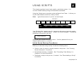
USING SCRIPTS .......................................................................................... 7-1
Initial Script Startup Procedures ............................................................... 7-1
Viewing Script Information ....................................................................... 7-2
Downloading a Script .............................................................................. 7-3
Enabling a Script .................................................................................... 7-4
Deleting a Script ..................................................................................... 7-5
Enabling Status Polling............................................................................ 7-6
Using Immediate Commands .................................................................... 7-7
iii
PRINTING ................................................................................................... 8-1
Printing .................................................................................................. 8-1
On-Demand Mode Printing ....................................................................... 8-2
Printing an Error Label ......................................................................... 8-2
Pausing a Batch...................................................................................... 8-3
Restarting a Batch .................................................................................. 8-3
Canceling a Paused Batch ....................................................................... 8-4
Repeating a Batch................................................................................... 8-6
Offline Printing ....................................................................................... 8-6
Special Printing Considerations ................................................................ 8-7
Printing TrueType® Fonts ........................................................................ 8-8
Licensing Your Fonts ............................................................................... 8-9
CARE AND MAINTENANCE .......................................................................... 9-1
Label Jams............................................................................................. 9-1
Cleaning ................................................................................................ 9-1
Replacing the Printhead .......................................................................... 9-5
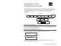
DIAGNOSTICS & TROUBLESHOOTING ....................................................... 10-1
Factory Set Password............................................................................ 10-1
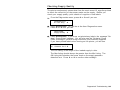
Checking the Software Version ............................................................... 10-1
Printing a Test Label ............................................................................. 10-2
Checking Supply Quality ........................................................................ 10-3
Using Password Protection .................................................................... 10-4
Enabling the Password (System Administrators only)............................. 10-4
Service Diagnostics............................................................................... 10-5
Troubleshooting .................................................................................... 10-6
Error Messages .................................................................................... 10-7
Common Errors ..................................................................................... 10-8
iv
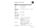
SPECIFICATIONS ........................................................................................A-1
Printer ................................................................................................... A-1
Tag Cut Dimensions ............................................................................. A-2
Supplies................................................................................................. A-3
Linerless Supplies ............................................................................... A-4
String Tag Supplies ................................................................................. A-4
Ribbon Specification ............................................................................... A-5
About Ribbons ..................................................................................... A-5
Cable Pinouts ......................................................................................... A-6
ACCESSORIES & OPTIONS ..........................................................................B-1
Accessories ............................................................................................ B-1
Packaging Materials ............................................................................. B-2
Factory-Installed Options ......................................................................... B-2
Ethernet Information ............................................................................ B-3
RF Information .................................................................................... B-3
GLOSSARY ................................................................................................ G-1
v
vi
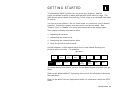
G E T T I N G S TA R T E D
1
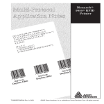
The Monarch® 9855™ printer lets you print text, graphics, and bar
codes on thermal transfer (ribbon) and thermal direct labels or tags. The
9855 printer prints labels continuously (in one strip) or on-demand (one label
at a time).
You can print on aperture, die cut, black mark, or continuous (non-indexed)
supplies. Continuous supply must be used in continuous mode. See
"Supply Type" in Chapter 4 for more information about the supply types.
This chapter includes information about
♦
unpacking the printer
♦
connecting the power cord
♦
connecting the communication cable
♦
using the printer's control panel.
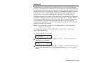
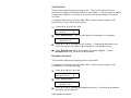
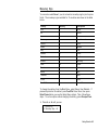
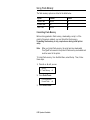
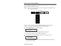
Several chapters of this manual have one or more charts showing the
printer's menu structure. For example:
Main Menu
C an c el
A ll
S u pp l y
Print
Mode
C ont r ast
B at c h
E nt r y
D ef a ult s
R ep eat
B at c h
N et w o rk
B at c h
O pti ons
P o rt
Sett in gs
S et up
S c r i pt s
D ia g.
Fl ash
Memory
V e rif ie r
R FI D
The black boxes show where you are; the bordered boxes show how you got
there.
Refer to the MonarchNet2™ Operating Instructions for information about the
Network menu.
Refer to the Multi-Protocol Application Notes for information about the RFID
menu.
Getting Started 1-1
Audience
The Operator's Handbook is for the person who prints and applies labels.
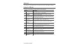
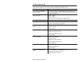
Using this Manual
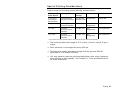
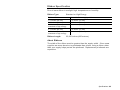
Following is a summary of the contents of this manual.
Chapter
Contents
1
Getting Started
Contains information about connecting the power
cable and using the control panel.
2
Loading
Supplies
Describes how to load a roll of supply, fan-fold
supply, and tag supply.
3
Loading Ribbon
Describes how to load a roll of ribbon and lists highenergy ribbon information.
4
Setting Supply
Options
Using the Supply menu to set the various supply
options (supply, ribbon, feed mode, etc.).
5
Setting
Communication
Values
Using the Port Settings menu to set the serial and
parallel communication values (baud rate, parity,
etc.).
6
Setting Defaults
Using the Defaults menu to set the monetary sign,
number of decimal places, prompt set, etc.
7
Using Scripts
Using the Scripts menu to load a script, enable a
script, delete a script, etc.
8
Printing
Explains how to print labels and use the Pause menu.
9
Care &
Maintenance
Describes how to clear a label jam, clean the printer,
and replace the printhead.
10
Diagnostics &
Troubleshooting
Describes how to print a test label and lists common
problems and their solutions.
A
Specifications
Contains printer and supply specifications.
B
Accessories &
Options
Contains printer accessories and optional equipment.
1-2 Operator’s Handbook
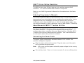
Unpacking the Printer
After you unpack the printer, you should have the printer, a power cord, and
a ribbon take-up core (may already be on take-up reel). Keep the box and
packaging material in case the printer ever needs repair.
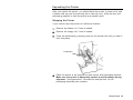
Shipping the Printer
If you need to ship the printer to a different location:
1.
Remove the ribbon roll, if one is loaded.
2.
Remove the supply roll, if one is loaded.
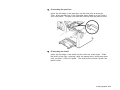
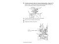
3.
Close the printhead by pressing down on the thumb well until you hear it
click into place.
Thumb Well
4.
Place the printer in the original box and secure with packaging material.
Make sure the printer is adequately packed to avoid damage during
shipment. See Appendix B, "Accessories and Options" for the
packaging materials part numbers.
Getting Started 1-3
9445™ Printer Online Emulation
The 9855 printer using 203 dpi (dots per inch) printing supports 94x5
emulation. You can send 94x5 data streams to this printer.
Refer to your 9445 Programmer's Manual for information about 94x5 data
streams.
Ordering Programmer's Manuals
The Packet Reference Manual, which describes how to create format and
batch packets for printing labels, how to configure the printer online, how to
diagnose printer error messages, and how to perform other advanced
techniques can be downloaded from our Web site (www.paxar.com). You
can print this manual or order a hard-copy version (part number TC9800PM).
About Monarch® MPCL™ Toolbox Utilities
The Monarch® MPCL™ Toolbox utilities are available on our Web site and
are free to download. This group of development utilities helps you
configure the printer, customize fonts, and download files. Monarch MPCL
Toolbox utilities are not label production software. Call Customer Service
for information about label production software.
Connecting the Power Cable
The power supply automatically switches between 115V or 230V. No
operator settings are required.
1.
Plug the power cable into the socket. Plug the other end of the cable
into a grounded electrical outlet.
Note:
2.
Only use a certified power cable with proper voltage for the country
of installation.
Turn on the printer. Press ( I ) to turn on and ( O ) to turn off the printer.
1-4 Operator’s Handbook
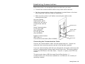
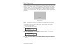
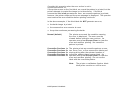
Establishing Communications
Before the printer can accept print jobs from the host, you must:
♦
Connect the communication cable to the printer and to the host.
♦
Set the communication values on the printer to match those at the host.
(Only required if you are using the serial port.)
♦
Make sure the printer is off before connecting the cable to the
communication port.
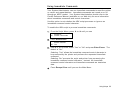
Ask your System
Administrator which
method you will use to
communicate with the
host:
Serial Communication
9 to 25-pin cable
(Part #126825)
25 to 25-pin cable
(Part #126826)
Parallel Communication
IEEE-1284 or
Centronics® mode cable (Part #126805)
Parallel Port
Pow er Cable
goes here
USB Port
Serial Port
Connecting the Communication Cable
Connect the communication cable into the appropriate port. Secure the
cable with the connecting screws (serial) or spring clips (parallel).
If you are communicating with the host through the serial port, make sure the
printer's communication values match those at the host. The factory default
values are 9600 Baud, 8 bit data frame, 1 stop bit, no parity, and DTR flow
control.
The printer also has a USB (Universal Serial Bus) Version 1.1
communication port. Drivers are available on our Web site for a variety of
operating systems.
Getting Started 1-5
Note:
The printer supports a baud rate up to 115200. Make sure your host
is capable of communicating at the speed you select for the printer.
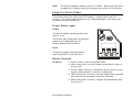
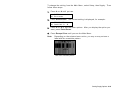
Using the Control Panel
The control panel has a two-line LCD display, 2 status lights, and five
buttons. The control panel displays error codes/messages, and allows you
to setup/configure the printer.
Printer Status Lights
Power:
The printer shows a steady green light
when it is on.
The Power light blinks when the battery
needs to be recharged (only on
battery-powered/cart models).
Fault:
The printer shows a blinking amber
light when there is a printer error.
Button Functions
Feed/Cut:
♦ Prints a label in the on-demand mode.
♦ When the printer is online, feeds a blank label if there is
no print job.
♦ Prints a label with error information that is useful to your
System Administrator if an error is displayed.
♦ When the printer is online, cuts the supply when pressed
and held for two seconds if a knife is installed.
♦ When the printer is offline, changes the displayed value
by one or 10.
1-6 Operator’s Handbook
Enter/Pause:
Escape/Clear:
When the printer is online, pauses the current print job
or resumes a paused print job. When the printer is
offline, selects the displayed menu item.
♦ When an error is present, clears the error.
♦ When a job (batch) is printing, cancels the print job
(batch). See "Canceling a Paused Batch" in Chapter 8
for more information.
♦ When the printer is online (without errors), enters the
offline menu mode.
♦ When the printer is in the offline menu mode, returns the
display to the next higher menu.
»
When the printer is in the offline menu mode, displays
the previous menu item.
¼
When the printer is in the offline menu mode, displays
the next menu item.
» and ¼
In online mode, prints a test label when you press the
buttons at the same time. Hold for one second and
release.
Display
The display shows a three-digit error code and brief message to identify any
problem the printer may have. For a description of the problem, look up the
error code in Chapter 10, "Diagnostics and Troubleshooting."
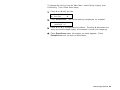
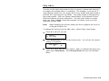
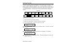
Selecting a Function
The Main menu has several functions (operating modes). These functions
are shown in the chart below.
Main Menu
C an c el
A ll
S u pp l y
Print
Mode
C ont r ast
B at c h
E nt r y
D ef a ult s
R ep eat
B at c h
N et w o rk
B at c h
O pti ons
P o rt
Sett in gs
S et up
S c r i pt s
D ia g.
Fl ash
Memory
V e rif ie r
R FI D
Getting Started 1-7
Note:
If the printer displays PRINT MODE Ready when you turn it on,
press Escape/Clear to display the Main menu.
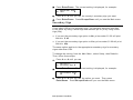
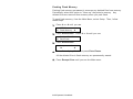
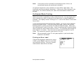
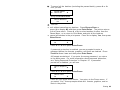
To display menu options, press » or ¼.
♦
When the screen displays a right arrow, press ¼ to display more options.
MAIN MENU
Cancel All
♦
¼
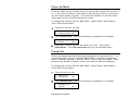
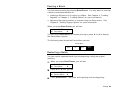
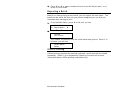
When the screen displays a left arrow, press » to display more options.
MAIN MENU
» Diagnostics
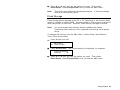
♦
When the screen displays a left and a right arrow, press either » or ¼ to
display more options.
MAIN MENU
» Print Mode
♦
¼
When you see the menu option you want, press Enter/Pause to select it.
The Main Menu controls the printer's setup and operation. Through the
Setup Menu, you can select a sub-menu for the supply, contrast, default, or
port settings. Each of those sub-menus have several options, such as
ribbon, speed, monetary symbols, and baud rate.
Exiting an Option
To exit an option, press Escape/Clear once. You will exit to the next higher
menu.
Note:
If you press Escape/Clear from a menu, your settings are not
saved. Your settings are only saved when you press Enter/Pause
from a menu.
1-8 Operator’s Handbook
LOADING SUPPLIES
2
This chapter describes how to load:
♦
a roll of supply
♦
fan-fold supply
♦
a roll of tag supply.
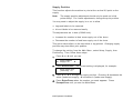
There are three types of supplies:
Thermal Direct
specially treated thermal supplies that do not use a
ribbon for printing.
Thermal Transfer
standard supplies that require a ribbon for printing.
High Energy
scratch, chemical, and temperature resistant supplies
that require a ribbon able to withstand high
temperatures. See "Using a High Energy Ribbon" in
Chapter 3 for more information.
If you are using thermal direct supplies, do not load a ribbon.
If you switch from black mark to die cut supplies, make sure the printer's
supply type is set correctly. See "Supply Type" in Chapter 4 for more
information. Your System Administrator can also send the supply setup
packet to change the supply type. Refer to the optional Packet Reference
Manual for more information about sending the supply setup packet.
Loading Supplies 2-1
Loading Labels or Tags
Make sure the printer is configured for the correct supply type.
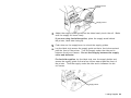
1.
Open the cover.
2.
Unlock the printhead by turning the retaining latch.
3.
Lift printhead assembly using the printhead tab until the assembly locks
into place.
Printhead Tab
Deflector Tab
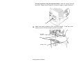
4.
Place the roll of supply on the supply holder. For labels, the supply
unrolls from the top or the bottom. For tags, make sure the supply
unrolls from the bottom, because tag rolls are wound face in.
Note:
Do not pick up the printer by the supply holder.
2-2 Operator’s Handbook
Supply Holder
Guides
Supply Roller
5.
Adjust the supply holder guides so the sides barely touch the roll. Make
sure the supply roll turns freely.
If you are using fan-fold supplies, place the supply stack behind
the printer, label side facing up.
6.
Push down on the supply lever to unlock the supply guides.
7.
Lay the label strip across the supply guide so that a few inches extend
past the front of the printer. Tuck the supply under the nibs and in
between the die cut sensor. Do not feed supply between the supply
roller and deflector.
For fan-fold supplies, lay the label strip over the supply holder and
across the supply guide so that a few inches extend past the front of
the printer. Tuck the supply under the nibs and in between the die
cut sensor.
Supply Roller
Loading Supplies 2-3
For tag supplies using the optional knife, feed the supply through
the knife. Make sure at least 0.5 inches of supply is past the knife.
Tag
8.
Adjust the supply guides so they touch the supply. Push up on the
supply lever to lock the supply guides into place.
Die Cut
Sensor
Nibs
Supply Le ver
2-4 Operator’s Handbook
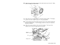
9.
Hold the printhead assembly by the printhead tab while pressing down on
the printhead release.
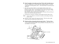
10. Close the printhead by pressing down on the thumb well until you hear it
click into place.
Thumb Well
11. Close the cover.
12. Press Feed/Cut to position the supply under the printhead.
Loading Supplies 2-5
You may need to adjust the wide/narrow knobs depending on the
width of your supply. See "Adjusting the Wide/Narrow Knobs" for
more information.
Note:
If the printer will be unused for extended periods of time, we
recommend leaving the printhead unlatched.
Loading Labels for the Optional Peel Mode
Peel mode is an option that must be purchased separately. In peel mode,
the printer separates the backing paper from the label. The next label is not
printed until the completed one is removed from the printer. Make sure the
printer is configured for on-demand mode and the correct supply type.
The minimum feed length is 1.5 inches for peel mode. We recommend using
0.5-inch gap supplies in peel mode when backfeed is disabled. Hold the
leading edge of peeled labels when printing on stock longer than six inches.
You must use non-perforated supplies for peel mode. Follow the steps for
loading supplies from the previous section. Then, follow these steps after
you close the printhead.
1.
Remove the labels from the first 10 inches of the backing paper.
2.
Press down on the exit cover tabs to open the exit cover on the front of
the printer.
Exit Cover
2-6 Operator’s Handbook
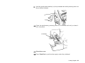
3.
Feed the backing paper over the peel bar.
Peel Bar
Low er Opening
4.
Feed the backing paper through the lower opening of the exit cover.
Close the exit cover. Pull down on the backing paper to remove any
slack.
Tear Edge
Backing Paper
When removing the backing paper, pull up across the sawtoothed tear edge. Make sure the backing paper tears at the edge.
Loading Supplies 2-7
5.
Close the printer's cover.
6.
Press Feed/Cut to position the supply under the printhead.
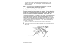
Using the Optional Tear Bar
Note the following change to loading labels if you have purchased the
optional tear bar. Tear labels against the tear bar. You cannot tear tags
with the tear bar.
Slide the supply between the tear bar and peel bar. It may be easier if you
cut or fold one corner of the supply first.
Tear Bar
Peel Bar
Do not tear both label and backing paper at the same time.
♦
Tear labels against the tear bar.
♦
Tear backing paper against the tear edge.
Tear Edge
Backing Paper
2-8 Operator’s Handbook
Using Linerless Supply
Linerless printing is an option that must be purchased separately on the
original printer order. The linerless option is not customer or fieldinstallable.
You must use thermal direct and black mark supplies for linerless
applications. The linerless printer must use on-demand mode.
For maximum platen roller life, use only wide or only narrow supplies.
Switching between wide and narrow supplies may lead to uneven platen
roller wear and possibly reduce the platen roller life. Use the narrow
setting for linerless supplies.
Note:
To prevent jams, do not leave the printhead closed (in the locked
position) longer than 30 minutes without printing. Open (unlock) the
printhead before a break period, at the end of each shift, and at the
end of each day.
Your linerless machine includes a shelf already installed. You can remove
the shelf and add the peel edge if you are not using linerless supplies.
Adding the Peel Edge or Shelf
1.
Turn off the printer.
2.
Open the cover.
3.
Unlock the printhead by turning the retaining latch.
4.
Lift the printhead assembly using the printhead tab until the assembly
locks into place.
Loading Supplies 2-9
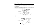
5.
Press down on the exit cover tabs to open the exit cover.
6.
Pull back slightly on the spring latch with your thumb or fingernail and lift
the shelf out.
CAUTION:
Be careful when inserting or removing the shelf. The shelf has
sharp points.
2-10 Operator’s Handbook
7.
If inserting the peel bar:
Insert the left edge of the peel bar into the side slot at an angle.
Then, slide the peel bar to the right and press down until you hear it
click into place. The peel bar must be lined up with the platen roller.
8.
If inserting the shelf:
Insert the left edge of the shelf into the side slot at an angle. Slide
the shelf to the right, aligning it with the spring latch, and press down
until you hear it click into place. The shelf must be lined up with the
platen roller.
Loading Supplies 2-11
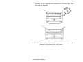
The shelf must be parallel to the platen roller, not at an angle. See
the following diagrams.
Shelf inserted correctly.
Shelf not inserted correctl y.
CAUTION:
Make sure the shelf is not misaligned with the platen roller, or
damage to the platen roller could occur.
2-12 Operator’s Handbook
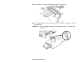
9.
Close the exit cover.
10. Load supplies by following the label loading procedures. You may notice
a different color and texture on the platen roller. Linerless supplies do
not stick to the textured platen roller.
11. Close the printhead assembly and the cover.
12. Turn on the printer.
13. Verify the alignment of the platen roller with the peel bar or shelf. Press
Feed/Cut to position the supply under the printhead.
14. Once linerless supply is loaded, slightly loosen the supply roll holders
from the edges of the supply roll. This allows linerless supplies to track
better.
Using String Tag Supply
String tags are used in a variety of applications, such as jewelry tags and
item marking.
String Tag Considerations
♦
Thermal direct printing, fan-fold supplies, and the knife are not supported
with string tags.
♦
The maximum print speed with string tags is 6.0 inches per second (ips).
♦
A non-print zone of 0.250 inches (6.4 mm) exists on the string side of the
tag.
♦
Use the wide setting for string tags.
Loading Supplies 2-13
Make sure the printer is configured for the correct supply type.
1.
Open the cover.
2.
Unlock the printhead by turning the retaining latch.
3.
Lift printhead assembly using the printhead tab until the assembly locks
into place.
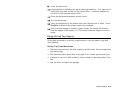
4.
Shake the roll of string tags down to untangle the roll.
5.
Place the roll of supply on the supply holder with the strings facing out.
2-14 Operator’s Handbook
6.
Adjust the supply holder guides so the sides barely touch the roll. Make
sure the supply roll turns freely.
7.
Push down on the supply lever to unlock the supply guides. The supply
guides have been angled slightly for string tag supplies.
8.
Lay the supply across the supply guide so that a few inches extend past
the front of the printer. Tuck the supply under the nibs and in between
the die cut sensor.
9.
Adjust the supply guides so they touch the supply. Push up on the
supply lever to lock the supply guides into place.
Die Cut
Sensor
Nib
Supply Le ver
Loading Supplies 2-15
10. Hold the printhead assembly by the printhead tab while pressing down on
the printhead release.
11. Close the printhead by pressing down on the thumb well until you hear it
click into place.
12. Close the cover.
13. Press Feed/Cut to position the supply under the printhead.
If the printer will be unused for extended periods of time, we recommend
leaving the printhead unlatched.
Adjusting the Wide/Narrow Knobs
You may need to adjust the two wide/narrow knobs according to the width of
your supply. For supply that is more than two inches, adjust the knobs to
the wide setting. For supply that is two inches or less, adjust the knobs to
the narrow setting. For linerless supply, use the narrow setting (knobs are
up). For string tag supply, use the wide setting (knobs are down).
You must adjust both of
the knobs to the same
position.
If you experience ribbon
smudging in cold, dry
environments, adjust the
wide/narrow knobs to the
wide setting.
For wide supplies, push
down and turn the
wide/narrow knobs
clockwise with a
screwdriver.
For narrow supplies, turn the wide/narrow knobs counter-clockwise with a
screwdriver until it pops back up.
Note:
The adjustment is shown in the wide position.
2-16 Operator’s Handbook
LOADING RIBBON
3
This chapter describes how to load a ribbon roll.
There are different ribbon requirements for the three types of supplies:
Thermal Direct
Supplies
do not use a ribbon for printing.
Thermal Transfer
Supplies
require a ribbon for printing.
High Energy
Supplies
require a ribbon able to withstand high temperatures.
If you are using thermal direct supplies, do not load a ribbon. If you are
using high energy supply, be sure to use a high energy ribbon. See "Using a
High Energy Ribbon" for more information. If you want to use a high energy
ribbon, select high energy for the ribbon every time the printer is turned on.
See "Ribbon" in Chapter 4 for more information.
Loading Ribbon 3-1
Loading Ribbon
Make sure the printer is configured to use a ribbon.
To load ribbon:
1.
Open the cover.
2.
Unlock the printhead by turning the retaining latch.
3.
Lift printhead assembly using the printhead tab until the assembly locks
into place.
Printhead
As sembl y
Deflector
Tab
4.
Push the deflector tab down.
5.
Slide the extra ribbon core on the take-up reel as far as it will go with the
"This End Out" writing facing out. Use your empty ribbon core as the
take-up core. The take-up core only fits on the take-up reel one way.
(An extra take-up core is available by ordering part number 117961.)
3-2 Operator’s Handbook
6.
Remove the new ribbon from the package as shown. Do not wrinkle or
crush the new ribbon.
7.
Slide the ribbon onto the back reel as far as it will go. The ribbon roll
only fits on the reel one way. Carefully unwind a few inches of ribbon
from the bottom of the roll.
Note:
Make sure the “Monarch This End Out” writing is facing out.
The ribbon only fits on the reel one way.
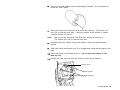
8.
Carefully feed the ribbon under both ribbon rollers and printhead as
shown.
9.
Align the ribbon and make sure it is straight and centered throughout the
path.
10. Tape the ribbon to the take-up core. Do not tape the ribbon to the
take-up reel.
11. Rotate the take-up core until the leader is past the printhead.
Take-up Core
Take-up Reel
Ribbon Rollers
Loading Ribbon 3-3
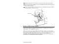
12. Remove any slack in the ribbon by turning the take-up reel clockwise.
13. Hold the printhead assembly by the printhead tab while pressing down on
the printhead release.
14. Close the printhead by pressing down on the thumb well until you hear it
click into place. Close the cover.
Thumb Well
Using a High Energy Ribbon
High energy ribbon is an option for this printer. It enables you to print on
high energy (TUFF-MARK®) supplies.
When you select high energy ribbon for the printer setting, you are setting
the printer to a higher printing temperature. Select this setting only after you
have loaded a high energy ribbon and supply or it may damage your
printhead. Select a high energy ribbon every time you turn on the printer.
See "Ribbon" in Chapter 4 for more information.
3-4 Operator’s Handbook
Note:
The high energy setting is lost when you turn off the printer.
High Energy Ribbon Limitations
When using the high energy ribbon option:
♦
Use a print speed of 2.5IPS (inches per second).
♦
Printhead warranty is reduced to 100,000 inches.
♦
Serial bar codes cannot be printed.
♦
Do not use peel mode.
♦
No more than 20% of the supply should have print (black coverage).
CAUTION:
The high energy ribbon may break or stick to the supply when
more than 20% of the supply contains print.
♦
Only white high energy supply should be used for bar code printing.
♦
Reverse fonts cannot be used.
♦
A non-printing area of at least .1 inch (2.54 mm) must exist on the left
and right edge of the ribbon.
♦
Do not print horizontal lines or bars.
♦
Graphics are limited.
Loading Ribbon 3-5
3-6 Operator’s Handbook
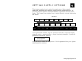
S E T T I N G S U P P LY O P T I O N S
4
This chapter explains how to select the supply type, ribbon, speed,
feed mode, backfeed, print position, supply position, margin position, cut
position, dispense position, backfeed distance, separators, and skip index
mode. This chapter also explains how to adjust the print contrast and enable
the verifier.
Main Menu
C an c el
All
S u pp l y
S u pp l y
T yp e
Print
Mode
C ont r ast
R ib bo n
S p ee d
B at c h
E nt r y
D ef a ult s
F ee d
Mode
R ep eat
B at c h
N et w o rk
B a c kf e ed
B at c h
O pti on s
P o rt
S et t i n gs
P o sit io ni n g
S c r i pt s
S et up
Fl ash
Memory
S e pa rat o rs
D ia g.
V e rif ie r
Skip
I nd ex
R FI D
Knife
Ct rl
E r r or
Action
Your System Administrator may limit access to this menu to prevent supply,
network, script, or communication settings from being changed. If password
protection is turned on, you see
Enter Password
_ _ _ _ _ _
when you try to access the setup menu. Get the password from your System
Administrator to continue.
Setting Supply Options 4-1
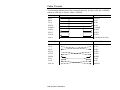
The options are listed in the table below.
Option
Choices
Default
Supply Type
Aperture/Die Cut/Black
Mark/Continuous
Die Cut
Ribbon
No/Yes/High Energy
Yes
Speed
2.5/4.0/6.0/8.0/10.0/12.0/Default
Default
Feed Mode
Continuous/On-Demand
Continuous
Backfeed
Off/On/Extended
Off
Print Position
-450 to 450
0
Supply Position
-300 to 300
0
Margin Position
-99 to 99
0
Cut Position
-300 to 300
0
Dispense
Position
50 to 200
65
Backfeed
Distance
10 to 200
65
Separators
No/Yes/Long
No
Skip Index
No/Yes
No
Knife Control
-20 to 20
0
Error Action
Normal
Overstrike/Continue
Overstrike/Continue
Overstrike/Continue
Overstrike/Continue
Overstrike/Continue
Contrast
-699 to 699
Normal
x1
x2
x3
x4
x5
0
To exit an option without changing the setting, press Escape/Clear.
4-2 Operator’s Handbook
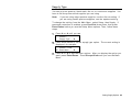
Supply Type
You can print on aperture, black mark, die cut, or continuous supplies. You
have to tell the printer which supplies you are using.
Note:
If you are using edge aperture supplies, use the die cut setting. If
you are using center aperture supplies, use the aperture setting.
To change the setting, from the Main Menu, select Setup, then Supply. If
password protection in enabled, press Feed/Cut three times, then press
Enter/Pause before you see the Setup Menu options. Then, follow these
steps.
1.
Press » or ¼ until you see
SUPPLY
Supply Type
2.
¼
Press Enter/Pause to set the supply type option. The current setting is
displayed, for example:
SUPPLY TYPE
» Black Mark
¼
3.
Press » or ¼ to see the other options. After you display the option you
want, press Enter/Pause. Press Escape/Clear until you see the Main
Menu.
Setting Supply Options 4-3
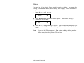
Ribbon
You have to tell the printer if your supplies require a ribbon. To change the
setting, from the Main Menu, select Setup, then Supply. Then, follow these
steps.
1.
Press » or ¼ until you see
SUPPLY
Ribbon
2.
Press Enter/Pause to set the ribbon option. The current setting is
displayed, for example:
RIBBON
» Yes
3.
¼
¼
Press » or ¼ to see the other options. After you display the option you
want, press Enter/Pause. Press Escape/Clear until you see the Main
Menu.
Note:
If you set the Ribbon option to Yes, install a ribbon before printing.
If you want to use a high energy ribbon, select high energy for the
ribbon every time the printer is turned on.
4-4 Operator’s Handbook
Speed
You can change the print speed for bar codes or graphics. If you select
"default" for speed, formats with serial bar codes automatically print at 2.5
ips and formats with parallel bar codes print at 6.0 ips. 12.0 ips printing is
an option that must be purchased separately.
To change the setting, from the Main Menu, select Setup, then Supply.
Then, follow these steps.
1.
Press » or ¼ until you see
SUPPLY
» Speed
2.
¼
Press Enter/Pause to set the speed option. The current setting is
displayed, for example:
SPEED
» Default
3.
Press » or ¼ to see the other options. After you display the option you
want, press Enter/Pause. Press Escape/Clear until you see the Main
Menu.
Note:
For additional high speed printing information, see Chapter 8,
"Printing."
Setting Supply Options 4-5
Feed Mode
You can use continuous or on-demand printing. On-demand printing allows
you to remove a label before printing the next one.
To change the setting, from the Main Menu, select Setup, then Supply.
Then, follow these steps.
1.
Press » or ¼ until you see
SUPPLY
» Feed Mode
2.
Press Enter/Pause to set the feed mode. The current setting is
displayed, for example:
FEED MODE
Continuous
3.
¼
¼
Press » or ¼ to see the other option. After you display the option you
want, press Enter/Pause. Press Escape/Clear until you see the Main
Menu.
4-6 Operator’s Handbook
Backfeed
Backfeed works by advancing each printed label to the desired dispense
position. Once that label is removed, the next label to be printed is backed
up underneath the printhead. In continuous mode, only the last label in the
batch is advanced to the dispense position. Extended backfeed is available
on this printer with a knife installed. Extended backfeed feeds a tag far
enough out to be cut and backfeeds the next tag to the printhead line.
Extended backfeed eliminates printed tags being left between the printhead
and knife. Extended backfeed works with the selected cut modes. Refer to
the optional Packet Reference Manual to learn how to define the Backfeed
Control Packet. Extended backfeed does not work with non-indexed
(continuous) supply/mode. Do not use backfeed (normal or extended) with
supplies less than 0.75 inches.
Note:
We recommend using 0.5-inch gap supplies in peel mode when
backfeed is disabled.
To change the setting, from the Main Menu, select Setup, then Supply.
Then, follow these steps.
1.
Press » or ¼ until you see
SUPPLY
» Backfeed
2.
Press Enter/Pause to set the backfeed option. The current setting is
displayed, for example:
BACKFEED
» On
3.
¼
¼
Press » or ¼ to see the other options. After you display the option you
want, press Enter/Pause. Press Escape/Clear until you see the Main
Menu.
Setting Supply Options 4-7
Positioning
This menu includes selections to change the print, supply, margin, cut, and
dispense positions along with the backfeed distance.
When you see
Enter print pos
[-450/450]: +0
Feed/Cut acts as a toggle switch to change the value by 10 or 1. For
example, to make the print position 23 (from the default of 0), press
Feed/Cut, then press » twice (20), press Feed/Cut again and press ¼ three
times (23).
Print Position
This function adjusts where data prints vertically on the supply. Adjust the
print if it is too close to the top or bottom of the supply, or overtypes the preprinted area. One dot is 0.0049 inch.
♦
If the data is too close to the bottom, increase the number.
♦
If the data is too close to the top, decrease the number.
Note:
Changing this setting only affects new formats sent to the printer.
4-8 Operator’s Handbook
To change the setting, from the Main Menu, select Setup, Supply, then
Positioning. Then, follow these steps.
1.
Press » or ¼ until you see
POSITIONING
» Print Pos
2.
¼
Press Enter/Pause. The current setting is displayed, for example:
Enter print pos
[-450/450]: +0
3.
Press » or ¼ to change the print position. Pressing » decreases the
value (moves the image down); ¼ increases it (moves the image up).
4.
Press Enter/Pause when the number you need appears. Press
Escape/Clear until you see the Main Menu.
Setting Supply Options 4-9
Supply Position
This function adjusts the machine to print at the vertical 0,0 point on the
supply.
Note:
The supply position adjustment should only be made on initial
printer setup. For format adjustments, change the print position.
You may need to adjust the supply in or out to allow
♦
tags and labels to be removed.
♦
die cut labels to be removed easily.
The adjustments are in dots (0.0049 inch).
♦
Increase the number to feed more supply out of the chute.
♦
Decrease the number to feed less supply out of the chute.
This option takes effect on the next label or tag printed. Changing supply
position may also affect print position.
To change the setting, from the Main Menu, select Setup, Supply, then
Positioning. Then, follow these steps.
1.
Press » or ¼ until you see
POSITIONING
» Supply Pos
2.
¼
Press Enter/Pause. The current setting is displayed, for example:
Enter supply pos
[-300/300]: +0
3.
Press » or ¼ to change the supply position. Pressing » decreases the
value (feeds less supply); ¼ increases it (feeds more supply).
4.
Press Enter/Pause when the number you need appears. Press
Escape/Clear until you see the Main Menu.
4-10 Operator’s Handbook
Margin Position
This function adjusts where the format prints horizontally on the supply. The
adjustments are in dots (0.0049 inch), which is the smallest measurement
the printer recognizes.
The width of the print area depends on your supply size. Maximum width is
four inches. When you move the image to the right or left on the supply,
avoid moving the image too close to either edge, because it may not print.
Print too far to the left.
Print too far to the right.
♦
If the data is too close to the left side, increase the number.
♦
If the data is too close to the right side, decrease the number.
Note:
Changing this setting only affects new formats sent to the printer.
To change the setting, from the Main Menu, select Setup, Supply, then
Positioning. Then, follow these steps.
1.
Press » or ¼ until you see
POSITIONING
» Margin Pos
2.
¼
Press Enter/Pause. The current setting is displayed, for example:
Enter margin pos
[-99/99]: +0
3.
Press » or ¼ to change the margin position. Pressing » decreases the
value (moves the image toward the left side of the supply); ¼ increases
it (moves the image toward the right side of the supply).
4.
Press Enter/Pause when the number you need appears. Press
Escape/Clear until you see the Main Menu.
Setting Supply Options 4-11
Cut Position
This function adjusts where the tag is cut. The printer adjusts the cut
position according to the black marks on the supply. You may need to adjust
for aperture supplies. Increase to move the cut up; decrease to move the
cut down.
To change the setting, from the Main Menu, select Setup, Supply, then
Positioning. Then, follow these steps.
1.
Press » or ¼ until you see
POSITIONING
» Cut Pos
2.
¼
Press Enter/Pause. The current setting is displayed, for example:
Enter knife adj
[-300/300]: +0
3.
Press » or ¼ to change the cut position. Pressing » decreases the
value (moves the cut down); ¼ increases it (moves the cut up).
4.
Press Enter/Pause when the number you need appears. Press
Escape/Clear until you see the Main Menu.
Dispense Position
This function adjusts the stopping point of the label.
To change the setting, from the Main Menu, select Setup, Supply, then
Positioning. Follow these steps.
1.
Press » or ¼ until you see
POSITIONING
»Dispense Pos
2.
¼
Press Enter/Pause.
DISPENSE POS
[50/200]: +65
3.
Press » or ¼ to change the dispense position. Pressing » decreases
the value; ¼ increases it.
4-12 Operator’s Handbook
4.
Press Enter/Pause when the number you need appears. Press
Escape/Clear until you see the Main menu.
Backfeed Distance
This is the amount to move the label backwards. The backfeed distance
cannot be greater than the dispense position. If you make the backfeed
distance greater than the dispense position, the dispense position
automatically changes to match the backfeed distance.
The backfeed distance should equal the dispense position. An exception is
when you are tearing labels, instead of peeling. Then, the backfeed distance
must be 30 dots (0.15 inches) less than the dispense position to account for
improper tearing of butt cut supplies. You will have a 30-dot non-print zone
on your supply, but this prevents exposed adhesive under the printhead.
To change the setting, from the Main Menu, select Setup, Supply, then
Positioning. Follow these steps.
1.
Press » or ¼ until you see
POSITIONING
» Backfeed Dis
2.
Press Enter/Pause.
BACKFEED DIS
[10/200]: +65
3.
Press » or ¼ to change the dispense position. Pressing » decreases
the value; ¼ increases it.
4.
Press Enter/Pause when the number you need appears.
Press Escape/Clear until you see the Main menu.
Setting Supply Options 4-13
Batch Separators
A batch separator is an extra tag printed in between batches with a pinstripe
pattern. If you select "Long" for the separator, a double-length (two tags)
separator prints. For non-indexed supply, the batch separator is always six
inches long. If you have the Monarch® 928™ stacker installed, the batch
separator is 3.66 inches long. The name of the batch is shown on the batch
separator.
Batch Separator
Note:
Changing this setting only affects new formats sent to the printer.
To change the setting, from the Main Menu, select Setup, then Supply.
Then, follow these steps.
1.
Press » or ¼ until you see
SUPPLY
» Separators
2.
Press Enter/Pause to set the batch separators option. The current
setting is displayed, for example:
SEPARATORS
No
3.
¼
¼
Press » or ¼ to see the other options. After you display the option you
want, press Enter/Pause. Press Escape/Clear until you see the Main
Menu.
4-14 Operator’s Handbook
Skip Index
You can use the skip index mode to skip (or ignore) a sense mark and print
an image over multiple labels, if necessary. For example, if you have 4.0"
long supplies loaded, but your image is 8.0" long, enable skip index mode to
print the 8.0" long image on two labels. The image length is determined by
the format header. See your System Administrator or the optional Packet
Reference Manual for more information. The skip index feature is useful
when you have a single format that contains two labels, such as a shelf
label and a carton label.
Note:
When designing the format, make sure text or graphics do not print
in the gap of label rolls.
To change the setting, from the Main menu, select Setup, then Supply.
1.
Press » or ¼ until you see
SUPPLY
» Skip Index
2.
Press Enter/Pause to set the skip index mode. You will see the current
setting, for example:
SKIP INDEX
No
3.
¼
Press » or ¼ to see the other options. After you display the option you
want, press Enter/Pause. Press Escape/Clear until you see the Main
Menu.
Setting Supply Options 4-15
Knife Control
You may notice unevenly cut tags on one end or the other of your supply
(one end may appear longer than the other). Use the knife control
adjustment to balance the cut tag length from tag-to-tag.
You may need to make this adjustment
♦
on initial printer setup.
♦
if you load a different supply type (thickness) from the last ones printed.
♦
when you change the print speed.
♦
when you change to a different tag size from the last ones printed.
To change the setting, from the Main Menu, select Setup, then Supply.
Then, follow these steps.
1.
Press » or ¼ until you see
SUPPLY
» Knife Ctrl
2.
Press Enter/Pause. The current setting is displayed, for example:
Enter knife ctrl
[-20/20]: +0
3.
Press » or ¼ to change the knife control. You may need to experiment
and cut a few test tags to check the tag cut length. Pressing »
decreases the value; ¼ increases it.
Note:
4.
Depending on how unevenly the tags are cut, always start with a
small number, such as +- 1 or 2.
Press Enter/Pause when the number you need appears.
Press Escape/Clear until you see the Main Menu.
4-16 Operator’s Handbook
Error Action
The recovery action from an error condition is in the Setup, Supply Menu.
You can change how the printer responds to a bad scan. The choices
include normal and overstrike/continue one to five consecutive bad scans.
The overstrike pattern is created to prevent someone from using a bad label.
Selecting overstrike and continue 1x-5x sets the number of times the printer
prints an overstrike pattern on consecutively bad labels before generating an
error. The user must clear the error before operation can continue.
Do not use the overstrike action with
♦
Peel mode
♦
Linerless supplies
♦
String tag supplies
For more information about the error actions, see the following table.
Error Action
Standard
Peel
Verifier
with Peel
RFID with
Peel
Overstrike/Continue 1-5
Normal (no overstrike)
No
Yes
No
Yes
No
Yes
Setting Supply Options 4-17
Consider this scenario when the error action is set to
overstrike/continue 3x:
If the printer errors on the first label, an overstrike pattern is printed, but the
printer attempts to reprint the image up to three times. If the third
consecutive label also generates an error, an overstrike pattern is printed;
however, the printer stops and the error message is displayed. The operator
must resolve the error condition before printing continues.
In the above example, if the third label did NOT generate an error,
♦
the batch image is printed
♦
the consecutive error counter is reset
♦
the printer continues processing the batch.
The printer errors and the condition causing
the error is displayed. The error must be
cleared before operation can continue. An
operator must press Escape/Clear to clear the
error and continue printing. No overstrike
pattern is printed.
Normal (default)
Overstrike/Continue
Overstrike/Continue
Overstrike/Continue
Overstrike/Continue
Overstrike/Continue
1x
2x
3x
4x
5x
The printer prints an overstrike pattern on one,
two, three, four, or five consecutive labels and
stops printing after the selected number of
overstrike patterns have been printed. An
operator must press Escape/Clear to clear the
error and continue printing. Do not use the
label with the overstrike pattern.
Note:
4-18 Operator’s Handbook
The printer re-calibrates (feeds a blank
label) after a motion or verifier error.
To change the setting, from the Main Menu, select Setup, then Supply. Then
follow these steps.
1.
Press » or ¼ until you see
SUPPLY
» Error Action
2.
Press Enter/Pause. The current setting is displayed, for example:
ERROR ACTION
» Ostrk/Cont 1x
¼
3.
Press » or ¼ to see the other options. After you display the option you
want, press Enter/Pause.
4.
Press Escape/Clear until you see the Main Menu.
Note:
Depending on the selected error action, you may or may not see a
label with the overstrike pattern.
Label w ith o verstrike pattern
Setting Supply Options 4-19
Setting Contrast
The print contrast controls the darkness of the printing on your supply. The
range is -699 to +699 and the default is 0. You may need to increase the
print contrast for linerless supplies. Having the correct print contrast setting
is important because it affects how well your bar codes scan and how long
your printhead lasts. You can use a verifier to check the bar code print
quality.
Main Menu
C an c el
All
S u pp l y
Print
Mode
C ont r ast
B at c h
E nt r y
D ef a ult s
R ep eat
B at c h
B at c h
O pti on s
N et w o rk
P o rt
S et t i n gs
S et up
Fl ash
Memory
S c r i pt s
V e rif ie r
D ia g.
R FI D
High contrast settings may
♦
require additional printhead cleaning.
♦
create bar code growth, leading to reduced scanning.
1.
From the Main Menu, press » or ¼ until you see
MAIN MENU
» Setup
2.
Press Enter/Pause. You will be at the Setup menu. Press » or ¼ until
you see
SETUP
» Contrast
3.
¼
¼
Press Enter/Pause. The current setting is displayed, for example:
Enter contrast
[-699/+699]: +0
4.
Press » or ¼ to change the contrast. Pressing ¼ darkens the print; »
lightens the print.
4-20 Operator’s Handbook
Feed/Cut acts as a toggle switch to change the value by 10 or 1. For
example, to make the contrast 50 (from the default of 0), press Feed/Cut,
then press ¼ five times (50).
5.
Press Enter/Pause to select either "Yes" or "No" to print a test label and
check the print contrast. Press Enter/Pause.
6.
Press Escape/Clear until you see the Main Menu.
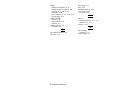
We recommend you check the bar code print quality with a bar code verifier.
If you do not have a bar code verifier or scanner, check the bar code
visually. A bar code that is in spec has complete bars, clear spaces, and
small alphanumeric characters look complete. An in spec bar code may not
look as good as one that is too dark, but it has the highest scan rate.
Dark
IN SPEC
Light
Setting Supply Options 4-21
Verifier
The verifier scans and checks the quality of bar codes as they are printed.
The optional verifier must be purchased separately. The verifier scans
parallel bar codes; it cannot scan serial bar codes.
The verifier must be enabled and set up before you can scan bar codes.
For additional set up procedures, refer to your verifier's Operating
Instructions for more information.
To enable the verifier, from the Main Menu, select Setup, then Verifier.
Then follow these steps.
1.
Press » or ¼ until you see
VERIFIER
» State
2.
Press Enter/Pause. The current setting is displayed, for example:
VERIFIER
Disabled
3.
¼
Press » or ¼ to see the other option. After you display the option you
want, press Enter/Pause. Press Escape/Clear until you see the Main
Menu.
4-22 Operator’s Handbook
S E T T I N G C O M M U N I C AT I O N S
5
This chapter tells you how to set the serial or parallel
communication values. These values provide the link for normal online
printing.
Main Menu
C an c el
All
S u pp l y
Print
Mode
C ont r ast
B at c h
E nt r y
D ef a ult s
S et up
S c r i pt s
D ia g.
P o rt
S et t i n gs
Fl ash
Memory
V e rif ie r
R FI D
S e ri al
Comm
P a ra l l el
Comm
R ep eat
B at c h
N et w o rk
B at c h
O pti on s
You need to set your Serial Comm values to match your computer's online
communications. Before entering the communication values, see your
System Administrator.
The serial communication values are listed in the table below.
Option
Choices
Default
Baud rate
1200/2400/4800/9600/19200/
38400/57600/115200
9600
Word length
7/8
8
Stop bits
1/2
1
Parity
None/Odd/Even
None
Flow control
None/Xon/Xoff/DTR/CTS
DTR
Reset
No/Yes
No
Setting Communications 5-1
Baud Rate
To change the setting, from the Main Menu select Setup, Port Settings, then
Serial Comm. If password protection in enabled, press Feed/Cut three
times, then press Enter/Pause before you see the Setup Menu options.
Then, follow these steps.
1.
Press » or ¼ until you see
SERIAL COMM
Baud Rate
¼
2.
Press Enter/Pause. The current setting is displayed, for example:
BAUD RATE
» 9600
¼
Press » or ¼ to display the baud rate you need, then press Enter/Pause.
Press Escape/Clear until you see the Main Menu.
Word Length
To change the setting, from the Main Menu select Setup, Port Settings, then
Serial Comm. Then, follow these steps.
1.
Press » or ¼ until you see
SERIAL COMM
» Word Length
¼
2.
Press Enter/Pause. The current setting is displayed, for example:
»
3.
WORD LENGTH
8
Press » or ¼ to display the word length you need, then press
Enter/Pause. Press Escape/Clear until you see the Main Menu.
5-2 Operator’s Handbook
Stop Bits
To change the setting, from the Main Menu select Setup, Port Settings, then
Serial Comm. Then, follow these steps.
1.
Press » or ¼ until you see
SERIAL COMM
» Stopbits
¼
2.
Press Enter/Pause. The current setting is displayed, for example:
STOPBITS
1
3.
¼
Press » or ¼ to display the number of stop bits you need, then press
Enter/Pause. Press Escape/Clear until you see the Main Menu.
Parity
To change the setting, from the Main Menu select Setup, Port Settings, then
Serial Comm. Then, follow these steps.
1.
Press » or ¼ until you see
SERIAL COMM
» Parity
¼
2.
Press Enter/Pause. The current setting is displayed, for example:
PARITY
None
3.
¼
Press » or ¼ to display the parity you need, then press Enter/Pause.
Press Escape/Clear until you see the Main Menu.
Setting Communications 5-3
Flow Control
To change the setting, from the Main Menu select Setup, Port Settings, then
Serial Comm. Then, follow these steps.
1.
Press » or ¼ until you see
SERIAL COMM
» Flow Control
¼
2.
Press Enter/Pause. The current setting is displayed, for example:
FLOW CONTROL
» DTR
¼
3.
Press » or ¼ to display the flow control you need, then press
Enter/Pause. Press Escape/Clear until you see the Main Menu.
XON is 17; XOFF is 19. Set flow control to DTR for PC computers
(unless you have XON/XOFF software).
Reset to Default Values
To change the setting, from the Main Menu select Setup, Port Settings, then
Serial Comm. Then, follow these steps.
1.
Press ¼ until you see
SERIAL COMM
» Reset
2.
Press Enter/Pause.
Are you sure?
No
3.
¼
Press » or ¼ to make your selection, then press Enter/Pause. If you
select "Yes," the following defaults are restored: 9600 baud, No parity, 8
bit word length, and 1 stop bit. Press Escape/Clear until you see the
Main Menu.
5-4 Operator’s Handbook
Parallel Communications
The parallel communications menu allows you to set the values for the active
parallel port. The values are listed in the table below.
Note:
Turn the printer off and back on when you change the port or mode
settings.
Option
Choices
Default
Port
External/Internal
External
Mode
Compatible/IEEE-1284
Compatible (Centronics mode)
Port
To change the setting, from the Main Menu select Setup, Port Settings, then
Parallel Comm. Then, follow these steps.
1.
Press » or ¼ until you see
PARALLEL COMM
Port
¼
2.
Press Enter/Pause.
PORT
External
¼
3.
Use » or ¼ to select either "External" or "Internal." Press Enter/Pause.
The internal port is used for printer options installed inside the printer,
such as the Ethernet communication port. The external port is used to
connect a printer cable or external device directly to the parallel port.
4.
Press Escape/Clear until you see the Main Menu.
Setting Communications 5-5
Mode
To change the setting, from the Main Menu select Setup, Port Settings, then
Parallel Comm. Then, follow these steps.
1.
Press » or ¼ until you see
PARALLEL COMM
» Mode
2.
Press Enter/Pause.
MODE
Compatible
¼
3.
Use » or ¼ to select either "Compatible" or "IEEE1284." Press
Enter/Pause. Use compatible mode for a computer connection to the
printer with a parallel cable. Use IEEE-1284 for bi-directional Ethernet
communications. See Appendix B, "Accessories and Options" for more
information about Ethernet options.
4.
Press Escape/Clear until you see the Main Menu.
5-6 Operator’s Handbook
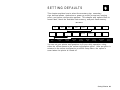
S E T T I N G D E FA U LT S
6
This chapter explains how to select the monetary sign, secondary
sign, decimal places, slashed zero, power-up mode, prompt set, imaging
errors, and ignore configuration packets. This chapter also explains how to
format flash, check the available flash memory, and pack flash memory.
Main Menu
C an c el
A ll
Print
Mode
S u pp l y
C ont r ast
Mo net a ry
S i gn
S e c on da r y
S i gn
B at c h
E nt r y
D ef a ult s
D e ci ma l
P l ac e s
R ep eat
B at c h
N et w o rk
S l as he d
Z er o
B at c h
O pti on s
P o rt
Sett in gs
Poweru p Mo de
S et up
S c r i pt s
D ia g.
Fl ash
Memory
V e rif ie r
R FI D
P r o mpt
S et
Fl ash
S t o ra ge
N o I ma ge
E r r or
I gn or e
C onf ig
You can set your printer configurations to fit your daily operation, using
either the offline menus or the online configuration option. After an option is
selected in the online configuration or offline Setup Menu, the option is
saved when the printer is turned off.
Setting Defaults 6-1
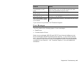
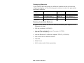
The monetary formatting options are listed in the table below.
Option
Choices
Default
Monetary sign
None/USA/UK/Japan/
Germany/France/Spain/
Italy/Sweden/Finland/
Austria/India/Russia/
Korea/Thailand/China/Euro-Dollar
USA
Secondary Sign
No/Yes
No
Decimal Places
0/1/2/3
2
Slashed Zero
No/Yes
No
Power-up Mode
Online/Offline
Online
Prompt Set
English/French/German/
Spanish-ES/Japanese/Portuguese/
Italian/Swedish/Spanish 2/
Danish/Dutch/Finnish/Norwegian
English
Flash Storage
Disabled/Enabled
Disabled
No Image Errors
Disabled/Enabled
Disabled
Ignore Config
Disabled/Enabled
Disabled
The monetary sign, secondary sign, and decimal places options are used in
conjunction with option 42. Refer to the optional Packet Reference Manual
for more information.
Note:
The settings for Monetary Sign, Secondary Sign, Slashed Zero, and
Decimal Places are applied when a format is downloaded. Changing
the settings does not affect batches already in the printer.
6-2 Operator’s Handbook
Monetary Sign
You can also select None if you do not want a monetary sign to print in price
fields. The monetary signs available for 15 countries are shown in the table
below.
Country
Currency
Description
USA
$
dollar
UK
£
pound
Japan
¥
yen
Germany
1
deutsche mark
France
F
franc
Spain
P
peseta
Italy
L.
lira
Sweden
Kr
krona
Finland
2
markka
Austria
6
schilling
India
Rs
rupee
Russia
3
ruble
Korea
won
Thailand
5
baht
China
¥
yuan
Euro-Dollar
€
euro-dollar
To change the setting, from the Main Menu, select Setup, then Defaults. If
password protection in enabled, press Feed/Cut three times, then press
Enter/Pause before you see the Setup Menu options. Then, follow these
steps. To exit an option without changing the setting, press Escape/Clear.
1.
Press Ù or Ú until you see
DEFAULTS
Ù Monetary Sign
Ú
Setting Defaults 6-3
2.
Press Enter/Pause. The current setting is displayed, for example:
MONETARY SIGN
» USA
¼
3.
Press » or ¼ until you see the country's monetary sign you want.
4.
Press Enter/Pause. Press Escape/Clear until you see the Main menu.
Secondary Sign
If you select USA as the monetary sign, you can print amounts less than
$1.00 either by using a dollar sign and decimal ($0.30) or by using a cent
sign (30¢).
♦
If you set the secondary sign option to No, prices under $1.00 will print
like this: $ .45
♦
If you set the secondary sign option to Yes, prices under $1.00 will print
like this: 45¢
The same option applies to the appropriate secondary sign for monetary
signs other than USA.
To change the setting, from the Main Menu, select Setup, then Defaults.
Then, follow these steps.
1.
Press » or ¼ until you see
DEFAULTS
» Secondary Sign ¼
2.
Press Enter/Pause. The current setting is displayed, for example:
SECONDARY SIGN
No
¼
3.
Press » or ¼ until you see the option you want. Then press
Enter/Pause. Press Escape/Clear until you see the Main menu.
6-4 Operator’s Handbook
Decimal Places
You can set the printer for 0, 1, 2, or 3 places after the decimal in a price
field. In U.S. currency, you might print prices like this: $24.00 (2 decimal
places) or like this: $24 (0 decimal places).
1.
Press » or ¼ until you see
DEFAULTS
» Decimal Places ¼
2.
Press Enter/Pause. The current setting is displayed, for example:
DECIMAL PLACES
» 2
¼
3.
Press » or ¼ until you see the option you want. Then press
Enter/Pause. Press Escape/Clear until you see the Main menu.
Slashed Zero
The slashed zero feature lets you select how you want the zero character
printed; either without a slash, 0 or, with a slash, Ø.
Standard or reduced fonts print the slashed zero character (Ø). Bold and
OCR fonts print the standard zero (0) only. The slashed zero selection will
not be in effect until the format is sent to the printer again. If you change
the way zero is printed, you must resend your formats.
To change the setting, from the Main Menu, select Setup, then Defaults.
Then, follow these steps.
1.
Press » or ¼ until you see
DEFAULTS
» Slashed Zero
2.
¼
Press Enter/Pause. The current setting is displayed, for example:
SLASHED ZERO
No
¼
3.
Press » or ¼ until you see the option you want. Then press
Enter/Pause. Press Escape/Clear until you see the Main Menu.
Setting Defaults 6-5
Power-Up Mode
Power-up mode lets you decide how your printer starts each time you turn it
on. If you want the printer to be ready to start printing when it is turned on,
use the Online power-up mode. If you want the operator to perform some
other task first, use the Offline power-up mode.
To change the setting, from the Main Menu, select Setup, then Defaults.
Then, follow these steps.
1.
Press » or ¼ until you see
DEFAULTS
» Powerup Mode ¼
2.
Press Enter/Pause. The current setting is displayed, for example:
POWER UP MODE
Online
¼
3.
Press » or ¼ until you see the option you want. Then press
Enter/Pause. Press Escape/Clear until you see the Main menu.
Prompt Set
Prompt set determines which language displays on the printer's menu. You
can select English, French, German, Spanish-ES, Japanese, Portuguese,
Italian, Swedish, Spanish 2, Danish, Dutch, Finnish, and Norwegian. Some
prompts may remain in English, even if you select a different language.
To change the setting, from the Main Menu, select Setup, then Defaults.
Then, follow these steps.
1.
Press ¼ until you see
DEFAULTS
» Prompt Set
2.
¼
Press Enter/Pause. The current setting is displayed, for example:
PROMPT SET
English
6-6 Operator’s Handbook
¼
3.
Press » or ¼ until you see the option you want. Then press
Enter/Pause. Press Escape/Clear until you see the Main menu.
Note:
This option only affects the displayed prompts. It does not change
what is printed by the printer.
Flash Storage
Flash storage allows packets (with "R" or "N" selectors) to be stored in flash
memory, instead of volatile RAM. Packets stored in flash memory are saved
when the printer is turned off. However, flash memory storage is limited.
Note:
You must format flash memory before enabling this option.
Formatting flash memory is only required once during initial printer
setup.
To change the setting, from the Main Menu, select Setup, then Defaults.
Then, follow these steps.
1.
Press ¼ until you see
DEFAULTS
» Flash Storage
2.
Press Enter/Pause. The current setting is displayed, for example:
FLASH STORAGE
Disabled
¼
3.
Press » or ¼ until you see the option you want. Then press
Enter/Pause. Press Escape/Clear until you see the Main menu.
Setting Defaults 6-7
No Image Errors
With version 5.2 or greater software, you can disable image error reporting.
Image errors occur when there is a problem producing a complete label.
You must press Escape/Clear to clear an image error.
Image errors include
600
unable to image batch
614
portion of field off label
601
problem during imaging
615
invalid PDF417 bar code data
603
missing batch
618
invalid font size
611
invalid font, bar code or density
620
missing font data
612
missing batch data
621
invalid downloaded font
613
reference point off label
622
not enough font memory
Note:
With this option enabled, the format may not print as expected and
no error is reported. For example, bar codes require a non-print
zone and if a bar code is placed too close to the edge of the label,
no error is reported and the bar code may not scan properly.
Error 616 (bar code dot shifting failed) is always reported.
To change the setting, from the Main Menu, select Setup, then Defaults.
Then, follow these steps.
1.
Press » or ¼ until you see
DEFAULTS
» No Image Error ¼
2.
Press Enter/Pause. The current setting is displayed, for example:
NO IMAGE ERRORS
Disabled
¼
3.
Press » or ¼ until you see the option you need. Then press
Enter/Pause.
4.
Press Escape/Clear until you see the Main Menu.
6-8 Operator’s Handbook
Ignore Configuration
With version 5.2 or greater software, you can ignore all online configuration
packets. If the printer receives data from a host system or software package
that includes online configuration packets with the format, those online
configuration packets can be ignored. Ignoring these packets is useful when
you cannot change your host’s data or when you want the printer to operate
as specified through the printer’s menu.
Note:
We recommend changing your host’s data stream, but if that is not
possible, enable this option.
Use caution if ignoring online configuration packets, because the
printer may need the configuration for proper operation.
To change the setting, from the Main Menu, select Setup, then Defaults.
Then, follow these steps.
1.
Press » or ¼ until you see
DEFAULTS
» Ignore Config
2.
Press Enter/Pause. The current setting is displayed, for example:
IGNORE CONFIG
Disabled
¼
3.
Press » or ¼ until you see the option you want. Then press
Enter/Pause.
4.
Press Escape/Clear until you see the Main Menu.
Setting Defaults 6-9
Using Flash Memory
The flash memory options are listed in the table below.
Option
Choices
Default
Format Flash
No/Yes
No
Unused Flash
NA
NA
Pack Flash
No/Yes
No
Formatting Flash Memory
Before storing packets in flash memory, downloading a script, or if the
printer's firmware is updated, you must format the flash memory.
Formatting flash memory is only required once during initial printer
setup.
Note:
When you format flash memory, the script and any downloaded
TrueType® fonts saved in the printer's flash memory are deleted and
must be resent to the printer.
To format flash memory, from the Main Menu, select Setup. Then, follow
these steps.
1.
Press Ù or Ú until you see
SETUP
Ù Flash Memory
2.
Ú
Press Enter/Pause.
FLASH MEMORY
Format Flash
Ú
3.
Press Enter/Pause.
6-10 Operator’s Handbook
Are you sure?
No
4.
¼
Press ¼ to display "Yes" and press Enter/Pause.
CREATING FLASH
FILE SYSTEM 1
The printer's flash memory is cleared and reformatted. This process may
take several minutes. The printer reboots automatically after formatting
flash memory. You need to resend any fonts you want to use to flash
memory again. You return to the "Print Mode Ready" menu.
Checking Available Flash Memory
If you receive errors when downloading a script or other packets, make sure
you have enough flash memory available.
Note:
When you format flash memory, the script and any downloaded
TrueType fonts saved in the printer's flash memory are deleted and
must be resent to the printer.
To check available flash memory, from the Main Menu, select Setup. Then,
follow these steps.
1.
Press » or ¼ until you see
SETUP
» Flash Memory
¼
2.
Press Enter/Pause.
3.
Press » or ¼ until you see
FLASH MEMORY
» Unused Flash
¼
4.
Press Enter/Pause. You see the number (in bytes) of available flash
memory.
Unused Flash
» 1006216_
5.
Press Escape/Clear until you see the Main menu.
Setting Defaults 6-11
Packing Flash Memory
Packing flash memory permanently removes any deleted files from memory.
Periodically select this option to "clean up" the printer's memory. Any
deleted files are removed from memory when you pack flash.
To pack flash memory, from the Main Menu, select Setup. Then, follow
these steps.
1.
Press » or ¼ until you see
SETUP
» Flash Memory
2.
¼
Press Enter/Pause. Press » or ¼ until you see
FLASH MEMORY
» Pack Flash
3.
Press Enter/Pause.
Are you sure?
No
4.
¼
Press ¼ to display "Yes" and press Enter/Pause.
All the deleted files in flash memory are permanently erased.
5.
Press Escape/Clear until you see the Main menu.
6-12 Operator’s Handbook
Memory Guidelines
Use these basic guidelines when storing files in your printer's memory.
♦
Your printer may have volatile RAM (packets deleted when the printer is
turned off), non-volatile RAM (packets saved when the printer is turned
off), and flash memory (packets saved when the printer is turned off).
Each printer has a different limit of available memory.
♦
Before you save any packets in flash memory, you must format flash
memory first. See "Formatting Flash Memory" for more information.
♦
Formats, graphics, and check digits can be saved in flash (but they are
also duplicated in RAM). Any packets saved in flash cannot exceed the
memory available in RAM.
♦
Fonts are stored differently in flash. For example, the 9825 printer has
very limited flash font memory and one TrueType font may exceed that
limit. If you print TrueType or double-byte Asian fonts, use a 9855 or
9860 printer with the extended memory option.
♦
There is not a 1-to-1 ratio between the memory in your printer and the
memory in your PC. For example, a file that is 5K in Windows may
require 15-20K to store in your printer.
♦
When using graphics, use the lowest-resolution graphic possible. If your
printer uses a 203 dpi printhead, the graphic's resolution should be 150
to 200 dpi. In fact, 96 dpi may work. Try to create the smallest file size
possible.
♦
Use temporary storage for graphics that are only used once or twice.
However, if you have a logo that is used on multiple formats, save the
graphic in flash. Once again, try to create the smallest file size possible
for your graphic.
♦
Each line in a packet requires the same amount of memory. The smaller
the format, the less memory required to save it.
Setting Defaults 6-13
Setting Batch Options
You can select Batch Options to change, which prompts appear during Batch
Entry mode and set default values for those prompts. Customizing which
prompts appear during batch entry can reduce the time it takes to enter data
for a format. If the optional knife is not installed, you can prevent those
prompts from appearing during batch entry mode. If you set a new default
value for an option, that value is used even if the prompt is not displayed. If
you do not change a default value for an option, the system default is used if
the prompt is not displayed.
Note:
Setting batch options requires the optional keypad, which must be
purchased separately.
Refer to your keyboard's Operating Instructions for more information.
Setting Up the Network Printer
Your System Administrator should refer to the MonarchNet2 Operating
Instructions (available on our Web site) for more information about your
network printer.
Setting Up the RFID Printer
Your System Administrator should refer to the Multi-Protocol Application
Notes (available on our Web site) for more information about setting up your
RFID printer.
6-14 Operator’s Handbook
USING SCRIPTS
7
This chapter explains how to load, enable, and delete scripts. You
can also enable status polling and immediate commands.
Using the Scripts menu requires custom software from Paxar. It allows you
to print data streams written for other printers.
Note:
Ignore these menus if you do not use Scripts.
Main Menu
C an c el
A ll
Print
Mode
L o ad
S c r ipt
B at c h
E nt r y
E n ab l e
S c r i pt
R ep eat
B at c h
S c r i pt
I nfo
B at c h
O pti on s
D el et e
S c r i pt
S et up
S t at u s
Po lli ng
D ia g.
S c r i pt s
I m me d
C o m ma nd
Your System Administrator may limit access to this menu to prevent supply,
network, script, or communication settings from being changed. If password
protection is turned on, you see
Enter Password
_ _ _ _ _ _
when you try to access the scripts menu. Get the password from your
System Administrator to continue.
Initial Script Startup Procedures
Before you can start using a script, check the following items:
♦
Check to see if a script is already loaded in the printer. See "Viewing
Script Information" to continue.
♦
Format flash memory, if needed. See "Formatting Flash Memory" in
Chapter 6 for more information.
♦
Download a script to the printer, if needed. See "Downloading a Script"
to continue.
Using Scripts 7-1
Viewing Script Information
1.
To see if your printer has a script loaded from the Main menu, press
» or ¼ until you see
MAIN MENU
» Scripts
¼
2.
Press Enter/Pause. If password protection in enabled, press Feed/Cut
three times, then press Enter/Pause before you see the Scripts Menu
options.
3.
Press » or ¼until you see
SCRIPTS
» Script Info
4.
¼
Press Enter/Pause. What you see depends on the script. If a script is
not loaded, you see "No script loaded." If a script is loaded, you see the
script name and version number, for example,
MYSTORE
Version 1.0
If a script is already loaded, see "Enabling a Script," to continue. If
you need to download a script, see "Formatting Flash Memory" in
Chapter 6.
7-2 Operator’s Handbook
Downloading a Script
Follow these instructions to download a script from the MS DOS prompt. Set
the communication parameters using the MODE command. Then, prepare
the printer to accept a script.
1.
From the printer's Script Menu, press » or ¼ until you see
SCRIPTS
Load Script
2.
¼
Press Enter/Pause.
Script Load
Ready
Note:
Only one script can be loaded in the printer at a time.
When downloading a script, if you receive an error:
♦
Check the available flash memory. See "Checking Available Flash
Memory" in Chapter 6 for more information.
♦
Format flash memory. See "Formatting Flash Memory" in Chapter 6 for
more information.
After downloading a script, if the script does not appear to be loaded, try
formatting flash memory and download the script again.
Using Scripts 7-3
Enabling a Script
The script must be enabled before you can use it.
To enable or disable a script:
1.
From the Script Menu, press » or ¼ until you see
SCRIPTS
» Enable Script
2.
¼
Press Enter/Pause.
Enable Script?
» Yes
3.
Use » or ¼ to select either "Yes" or "No" and press Enter/Pause.
Selecting "Yes" starts the script. Selecting "No" stops the script. If you
select "Yes," when you turn off the printer and turn it back on, the script
automatically starts.
Once the script is enabled, you will see
Print Mode
S Ready
The "S" in the lower left-hand corner of the screen indicates the
printer has a script loaded and enabled (the script is running).
7-4 Operator’s Handbook
Deleting a Script
You can delete a script from the printer's memory.
To delete a script:
1.
From the Script Menu, press » or ¼ until you see
SCRIPTS
» Delete Script
2.
¼
Press Enter/Pause.
Are you sure?
» Yes
3.
Use » or ¼ to select either "Yes" or "No" and press Enter/Pause.
Selecting "Yes" deletes the current script.
Note:
4.
The flash memory used by the script is not available for other scripts
or fonts until the flash memory is reformatted. However, when you
format flash memory, you must resend the script and any
downloaded fonts to the printer.
Press Escape/Clear until you see the Main Menu.
Using Scripts 7-5
Enabling Status Polling
Status polling allows you to obtain information about the readiness of the
printer and the current (or last received) print job. Your System
Administrator can enable status polling while the printer is running in Script
mode. To enable status polling:
1.
From the Script Menu, press » or ¼ until you see
SCRIPTS
»Status Polling
2.
Press Enter/Pause.
Enable Polling
No
3.
¼
¼
Use » or ¼ to select either "Yes" or "No" and press Enter/Pause.
The default is "No."
7-6 Operator’s Handbook
Using Immediate Commands
Your System Administrator can use immediate commands to reset the printer
or cancel and repeat batches. Immediate commands are turned on or off
through an MPCL packet. Your System Administration should refer to the
Packet Reference Manual (available on our Web site) for more information
about immediate commands and control characters.
Use this option to set whether the ADK script processes or ignores an
immediate command control character.
To enable the ADK script to process immediate commands:
1.
From the Script Menu, press » or ¼ until you see
SCRIPTS
» Immed Commands
2.
Press Enter/Pause.
Enable Immed?
» Yes
3.
Use » or ¼ to select either "Yes" or "No" and press Enter/Pause. The
default is "No."
Selecting "Yes" allows the immediate command control character to
be processed by the printer and performs the requested immediate
command.
Selecting "No" prevents the script and printer from processing the
immediate command control character. Instead, the immediate
command control character and immediate command are treated as
data.
4.
Press Escape/Clear until you see the Main Menu.
Using Scripts 7-7
7-8 Operator’s Handbook
PRINTING
8
This chapter explains how to
♦
use on-demand mode printing.
♦
print an error label.
♦
print, pause, restart, cancel, and repeat a batch.
You can send format, batch, and graphic data to the printer from a host.
When the printer receives the data, batches begin printing automatically.
The optional Packet Reference Manual tells how to create, store, and
download the data necessary to print batches. You can also use the
Monarch® MPCL™ Toolbox utilities to create and download packets.
Main Menu
C an c el
A ll
Print
Mode
B at c h
E nt r y
R ep eat
B at c h
B at c h
O pti on s
S et up
S c r i pt s
D ia g.
Print
Mo de
R ea d y
Printing
Before you print, make sure the printer is connected and ready to receive
data.
1.
Turn on the printer. Your printer is ready to receive and print batches
when you see "PRINT MODE Ready."
2.
Download a format and a batch. Refer to the optional Packet Reference
Manual for information on downloading print jobs.
3.
The printer prints a strip of labels.
4.
Remove the printed labels.
Printing 8-1
Note:
If the printer will be unused for extended periods of time, we
recommend leaving the printhead unlatched.
An optional keyboard is also available to enter offline batch data. The
keyboard must be purchased separately. If there are offline batches in the
print queue, the offline batches print after the downloaded batches have
printed.
On-Demand Mode Printing
When this printer is operating in the on-demand mode, the next label prints
when the previous label is removed from the printer or when Feed/Cut is
pressed. The display shows "Printing X of Y" until all the labels in the batch
are printed.
If you have purchased the optional peel module, you must use on-demand
printing with peel mode. If you are using peel mode, remove the excess
backing paper by pulling up across the saw-toothed tear edge. Make sure
the backing paper tears at the edge. Hold the leading edge of peeled labels
when printing on stock longer than six inches. The minimum feed length for
peel mode is 1.5 inches. You must use non-perforated supplies for peel
mode. The maximum speed for peel mode is 8.0 ips.
Note:
We recommend using 0.5-inch gap supplies in peel mode when
backfeed is disabled.
Printing an Error Label
If the printer displays a data error (errors
0-499), press Feed to print an error label
and continue printing. See your System
Administrator about the error label.
8-2 Operator’s Handbook
Pausing a Batch
You can pause printing by pressing Enter/Pause. You may want to interrupt
a batch to make adjustments for:
♦
Loading a different roll of supply or a ribbon. See Chapter 2, "Loading
Supplies" or Chapter 3, "Loading Ribbon" for more information.
♦
Adjusting the supply position or contrast using the Setup menu. See
Chapter 4, "Setting Supply Options" for more information.
When you press Enter/Pause you will see
PAUSE MENU
» Print Mode
¼
You can press Enter/Pause to resume printing or press » or ¼ to display
the Pause Menu options.
The following chart shows the Pause Menu options.
Pause Menu
C an c el
B at c h
C an c el
A ll
Print
Mode
R e sta rt
B at c h
Restarting a Batch
You can reprint a paused batch from the beginning (using the original
quantity).
1.
When you press Enter/Pause, you will see
PAUSE MENU
» Print Mode
2.
Press » or ¼ until you see
PAUSE MENU
» Restart Batch
3.
¼
¼
Press Enter/Pause. The batch starts printing from the beginning.
Printing 8-3
Canceling a Paused Batch
You can cancel a paused batch, delete a format, graphic, or font in memory,
or all the batches waiting to print.
Note:
Before any format, graphic, or font in memory can be deleted, you
must cancel all batches.
Pause Menu
C an c el
B at c h
C an c el
A ll
Print
Mode
R e sta rt
B at c h
C an c el
B at c h
C an c el
F or m at
C an c el
G ra ph ic
C an c el
F ont
You can cancel a batch by pressing Escape/Clear while the batch is
printing, or you can use the Pause menu to cancel a batch.
1.
Press Enter/Pause to interrupt printing.
PAUSE MENU
» Print Mode
¼
♦
If you want to cancel only the paused batch, skip step 3.
♦
If you want to cancel all the batches, skip step 2.
2.
To cancel only the paused batch, press » or ¼ until you see
PAUSE MENU
Cancel Batch
¼
Then press Enter/Pause. The batch is deleted and the printer prints
any remaining batches.
8-4 Operator’s Handbook
3.
To cancel all the batches (including the paused batch), press » or ¼
until you see
PAUSE MENU
» Cancel All
¼
and press Enter/Pause.
Cancel Batches?
No
¼
4.
You can
♦ exit without canceling any batches. Press Escape/Clear or
press ¼ to display No and then press Enter/Pause. The printer returns
to the Pause menu. Press » or ¼ to select another function from the
Pause Menu, or to return to Print Mode and print all the batches.
♦ cancel all batches in the print queue. Press ¼ to display Yes, then press
Enter/Pause.
Cancel Format?
No
¼
Press » or ¼ then press Enter/Pause.
If password protection is enabled, you are prompted to enter a
password before the formats, graphics, and fonts are deleted. Press
Feed/Cut three times and then press Enter/Pause.
All formats are deleted. If you enter the wrong password, you return
to the Main menu. For more information about password protection,
see "Using Password Protection" in Chapter 10. If password
protection is disabled, you will see
Cancel Graphic?
No
¼
Press » or ¼ then press Enter/Pause.
Cancel Font?
No
¼
Press ¼, then press Enter/Pause. You return to the Pause menu. If
you select "Yes," these prompts delete ALL formats, graphics, and/or
fonts in the printer.
Printing 8-5
5.
Press » or ¼ to select another function from the Pause menu, or to
return to Print mode.
Repeating a Batch
Before you start printing a new batch, you can reprint the last batch. The
batch can be either the last one you printed completely or one that you
canceled after starting to print.
1.
From the Main Menu, press » or ¼ until you see
MAIN MENU
» Repeat Batch
2.
¼
Press Enter/Pause.
Printing
xxxx of xxxx
The number increments until the entire batch has printed. When it is
finished, you will see
PRINT MODE
Ready
Offline Printing
Offline printing requires the optional keyboard, which must be purchased
separately. Refer to your keyboard's Operating Instructions for more
information about offline printing and batch entry.
8-6 Operator’s Handbook
Special Printing Considerations
Keep in mind the following special printing considerations.
Maximum
Print Speed
Printing Method
Printhead
Density
Knife
Peel Mode
2.5/4.0/6.0
ips (inches
per second)
Thermal Direct
Thermal Transfer
203/300 dpi
dots per inch
Supported
Supported
8.0 ips
Thermal Direct
Thermal Transfer
203/300 dpi
Not
Supported
Supported
10.0 ips
Thermal
Direct/Thermal
Transfer
203 dpi only
Not
Supported
Not Supported
12.0* ips
Thermal
Direct/Thermal
Transfer
203 dpi only
Not
Supported
Not Supported
*12.0 ips is the high speed option, which must be purchased separately.
♦
The minimum label feed length is 0.75 inches (19 mm) using 8.0 ips or
higher.
♦
94x5 emulation is not supported using 300 dpi.
♦
The maximum supply and image length with the optional 300 dpi
printhead is 12.0 inches (305 mm).
♦
You may need to clean the printhead and platen roller more frequently
when printing at high speeds. See Chapter 9, "Care and Maintenance,"
for more information.
Printing 8-7
Printing TrueType® Fonts
TrueType® fonts are available on this printer. TrueType fonts are scalable
and the characters print smoothly, without the jagged edges you see on
bitmap fonts. When downloading a TrueType font, you download the entire
font. You cannot specify a subset (particular characters or point size) of the
font.
Note:
These font files may be very large and image slower than bitmap
fonts. The size of the font file, in bytes, is the minimum amount of
memory you must have available for fonts in the printer's memory.
Your System Administrator may need to reconfigure the printer's memory to
use downloaded TrueType fonts. Refer to the optional Packet Reference
Manual (available on our Web site) to learn how to reconfigure the printer's
memory. After reconfiguring memory, resend the font, format, and batch
packets.
This printer can accept a TrueType font file that has been converted to Hex
or Run-Length encoding using the version of Font Utility. Font Utility is
available on our Web site (www.paxar.com). Font Utility is a part of the
Monarch MPCL Toolbox Utilities. You can also use a wide variety of Code
Pages with International (Turkish, Latin, Spanish, etc.) characters. Using
TrueType fonts allows you a greater range of fonts for your formats.
TrueType fonts are designed to be regionally specific; therefore, all Code
Pages may not be supported in a given font. Check with your System
Administrator if you need to use TrueType fonts.
8-8 Operator’s Handbook
Licensing Your Fonts
We provide the Font Utility to help you create and download international
code pages/characters. However, it is your responsibility to license the fonts
you purchase and download to your printer. Contact your font supplier for
licensing information.
Additional fonts that are compatible with this printer can be purchased from:
The Electronic Font Foundry
11 Silwood Road
Ascot
SL5 OPY
England
(0)1344 875 201
www.eff.co.uk
Printing 8-9
8-10 Operator’s Handbook
CARE AND MAINTENANCE
9
This chapter tells you how to
♦
clear label jams and clean the printer.
♦
replace a printhead.
CAUTION:
Do not use sharp objects to clean the printhead or touch the
printhead with your fingers. This may damage the printer and
require a service charge.
Label Jams
When you are printing and a jam occurs, the Fault light on the printer's front
panel blinks. To clear the jam:
1.
Turn off the printer and open the cover and printhead assembly.
2.
If necessary, remove the label roll and ribbon.
3.
Remove the jammed labels and reload the label roll.
4.
Close the printhead assembly and turn on the printer.
5.
Press Feed/Cut to position the supply under the printhead.
Cleaning
The rate and frequency at which you print determines how often you must
clean the printer.
Note:
You must clean the printhead as described below to maintain
printhead life.
Care and Maintenance 9-1
You may need to clean the printhead, sensor, and platen roller:
♦
if there is any adhesive build-up in the supply path.
♦
after printing approximately 3 rolls of thermal
transfer/thermal direct/linerless supplies or
after each ribbon.
♦
daily if your printer is in an excessively dirty,
hot, or humid environment.
♦
when you see voids or streaking in the print
as shown.
When you are using higher speeds (with 203 or
300 dpi), and/or increased print contrast, we
recommend cleaning the printhead after each
ribbon with isopropyl alcohol. If you still notice
build-up on the printhead or black streaks on
your supply, order a printhead CLEAN-STRIP.
Voids
Streaks
1.
Turn off the printer and open the cover and printhead assembly.
2.
Remove the label roll and ribbon (when cleaning the printhead).
3.
Press down on the exit cover tabs to open the exit cover on the front of
the printer.
Exit Cover
9-2 Operator’s Handbook
4.
Clean the platen roller when you see significant adhesive build-up or a
label is wrapped around the platen roller. Use a dry, soft-bristle brush,
such as a toothbrush, to clean either the standard (black) or linerless
(red/orange textured) platen roller. If the brush does not remove all the
adhesive
♦
Use isopropyl alcohol ONLY on the standard (black) platen roller.
Moisten a cotton swab with isopropyl alcohol and run the cotton swab
across the platen roller. Turn the platen roller with your finger to make
sure the platen roller is clean all the way around.
After cleaning, feed several inches of supply through without printing to
remove any remaining isopropyl alcohol.
♦
Call Service to clean the linerless (red/orange textured) platen roller.
Note:
Do not use alcohol or solvents on linerless (red/orange textured)
platen rollers.
5.
Moisten a cotton swab with isopropyl alcohol. Rub the cotton swab
across the peel bar and remove any build-up.
6.
Moisten another cotton swab with isopropyl alcohol. Rub the cotton
swab across the printhead and remove any build-up. You may need to
use a printhead CLEAN-STRIP if the printhead is extremely dirty or you
see streaks on the supply.
Printhead
Care and Maintenance 9-3
7.
Rub the cotton swab across the supply sensor and die cut sensor and
remove any build-up.
Die Cut Sensor
Supply Sensor
8.
Clean the build-up in the supply path.
9.
Let the printer dry before you reload supplies.
10. Close the exit cover by pushing firmly on it. Both latches will click into
place.
11. Close the cover and printhead assembly.
12. Turn on the printer.
13. Press Feed/Cut to position the supply under the printhead. Resend your
format, batch, and check digit packets.
9-4 Operator’s Handbook
Replacing the Printhead
You may have to replace the printhead if it is damaged or worn-out. For
example, you may see 616 (bad dot or dots) or 768 (printhead failure) error
codes. See Appendix B, "Accessories and Options" for the printhead part
number.
CAUTION:
The printhead is sensitive to static electricity, which can
damage the printhead or reduce its life. Ground yourself by
touching some metal, such as the printer's metal base, before
touching the printhead. Clean the printhead to remove any salt
or oil left from handling prior to operation.
To replace the printhead:
1.
Turn off the printer.
2.
Open the cover.
3.
Unlock the printhead by turning the retaining latch.
4.
Press forward and down on the two latches on top of the printhead
assembly as shown. The printhead will drop down.
5.
Lift the printhead assembly using the printhead tab and push back until
the printhead assembly clicks into place.
Care and Maintenance 9-5
6.
Carefully unplug the cable from the printhead as shown. The printhead
is sensitive to static electricity, which can damage the printhead or
reduce its life. Ground yourself by touching some metal, such as the
printer's metal base, before touching the printhead.
7.
Carefully plug the cable into the new printhead.
8.
Align the new printhead with the tabs.
9.
Snap the printhead into place.
Do not
touch here
9-6 Operator’s Handbook
Note:
Make sure the printhead cable does not touch the ribbon roll.
10. Clean the new printhead with a cotton swab dipped in isopropyl alcohol
to remove any salt or oil left from handling.
11. Let the printhead dry and reload your supplies.
12. Close the printhead assembly and the cover. Turn on the printer.
13. Press Feed/Cut to position the supply under the printhead.
Care and Maintenance 9-7
9-8 Operator’s Handbook
10
DIAGNOSTICS &
TROUBLESHOOTING
This chapter explains how to perform simple diagnostic functions such as
checking the software version, the supply quality, printing test labels, and
using password protection. It also contains basic troubleshooting
information.
Main Menu
C an c el
All
Print
Mode
B at c h
E nt r y
R ep eat
B at c h
V e r si on
S u pp l y
Q ua lit y
B at c h
O pti on s
S et up
S c r i pt s
D ia g.
S e r vi ce
D ia g
U s er
D ia g
T est
L a bel
P a s sw or d
Factory Set Password
You need a password to access diagnostic functions. Press Feed/Cut three
times and then press Enter/Pause.
Checking the Software Version
1.
From the Diagnostics Menu, press » or ¼ until you see
DIAGNOSTICS
Version
¼
2.
Press Enter/Pause. You will see
Model M9855
V 1.0
Line one lists the printer model number (M9855) and line two gives the
version of software in the printer.
Diagnostics & Troubleshooting 10-1
Printing a Test Label
1.
From the Diagnostics Menu, press » or ¼ until you see
DIAGNOSTICS
» User Diag
¼
2.
Press Enter/Pause and ¼ until you see
USER DIAG
» Test Label
3.
Press Enter/Pause. The following test labels print.
The first label shows the printer's configuration by packet (A-G). The second
label shows the model number, software version, stock count, voltage, print
contrast, printhead resistance, number of bad dots, and installed options.
The test label also shows an inch count for the high energy ribbon. This
information will help Technical Support diagnose the problem. Refer to the
optional Packet Reference Manual for more information about the test label.
You can also print a test label by pressing » and ¼ at the same time. Hold
for one second and release. If test labels do not print, call Technical
Support.
10-2 Operator’s Handbook
Checking Supply Quality
The printer continuously stores data from the most recent 16 supplies printed
to check the reflectivity of the sensor marks on the supply. Before you
check your supply quality, print a batch of supplies or test labels.
1.
From the Diagnostics menu, press » or ¼ until you see
DIAGNOSTICS
» User Diag
¼
2.
Press Enter/Pause. You will be at the User Diagnostics menu.
Press » or ¼ until you see
USER DIAG
Supply Quality
3.
¼
Press Enter/Pause. If you have not printed any labels, the message "No
data! Press Enter" appears. You will also see the "No data! Press
Enter" message if you are using continuous (non-indexed) supplies.
If you have printed labels since turning on the printer, you will see
Len Min Max OK
» 1568 034 124 Y ¼
The Len listing is the length of the loaded supply in dots.
The Max listing should always be greater than the Min listing. The
OK listing tells whether the sense mark on the supply passed a
detection test. Press » or ¼ to see the other readings.
Diagnostics & Troubleshooting 10-3
Using Password Protection
The password protection feature prevents formats, graphics or fonts from
accidentally being deleted from the printer's memory. It also limits access to
the Setup and Scripts menus.
Enabling the Password (System Administrators only)
A System Administrator can enable the password that must be entered
before formats, graphics or fonts can be deleted.
1.
From the Main Menu, press » or ¼ until you see
MAIN MENU
» Diagnostics
2.
Press Enter/Pause. You will see
Enter Password
_ _ _ _ _ _
3.
Enter the password: press Feed/Cut three times and then press
Enter/Pause.
If you enter the wrong password, you return to the Main Menu.
4.
From the Diagnostics Menu, press » or ¼ until you see
DIAGNOSTICS
» User Diag
5.
Press Enter/Pause. Then, press » or ¼ until you see
USER DIAG
» Password
6.
Press Enter/Pause. You will see
Enable Password?
» No
The default for password protection is "No," so you will always see
"No" even if passwords are enabled.
10-4 Operator’s Handbook
7.
If you do not want the user to enter a password before they can delete
formats, graphics, fonts, or access to the Setup and Scripts menus,
press Enter/Pause. You return to the User Diagnostics Menu.
OR
Press ¼ to display "Yes" and press Enter/Pause. The password
protection is enabled for formats, graphics, fonts, and access to the
Setup and Scripts menus. You return to the User Diagnostics Menu.
8.
Press Escape/Clear twice to exit to the Main Menu.
Note:
When password protection is enabled, a password is not required to
clear batches, but it is needed to clear formats, graphics, and fonts.
Service Diagnostics
The Service Diagnostics menu can only be accessed by a Paxar
Representative, because it requires a separate password. If you need to call
Technical Support, print a test label first.
Diagnostics & Troubleshooting 10-5
Troubleshooting
This section helps you correct some problems that may occur.
Problem
Action
Error message appears
during startup.
Turn off the printer. Wait fifteen seconds and then
turn on the printer. Call Technical Support if the error
message reappears.
Does not print.
Check supply.
Check ribbon.
Send a corrected format and batch packet.
Does not feed.
Set wide/narrow knobs correctly.
Partially printed data.
Clean the printhead.
Send a corrected format packet.
Printing shadows or
smears.
Clean the printhead.
Change supply.
Check ribbon.
Light printing.
Change supply.
Adjust the print contrast.
Check wide/narrow knobs.
Check ribbon.
Heavy printing.
Clean the printhead.
Change supply.
Adjust the print contrast.
Check wide/narrow knobs.
Check ribbon.
Voids in printing.
Clean the printhead.
Change supply type.
Check ribbon.
Serial bar codes do not
print.
Leave printhead unlatched when not in use.
Use a print speed of 2.5 IPS.
Adjust the print contrast.
10-6 Operator’s Handbook
Problem
Action
Backing paper is wrapped
around platen or peel
roller.
Carefully remove the backing paper. Make sure the
backing paper tears at the saw-toothed tear edge
when using backfeed and peel mode.
Blank labels print or 750
series errors.
Clean supply sensors.
When downloading a script,
the printer errors.
Check the available flash memory. Format flash
memory or clear NVRAM.
After downloading a script,
the script does not appear
to be loaded.
Try formatting flash memory, then download the script
again.
If you cannot fix a problem, call Technical Support.
Error Messages
You may receive the following types of error messages:
♦
Data Errors
♦
Communication Errors
Some errors numbered 400-438 and 500-574 are internal software errors.
Errors numbered 900-999 are hard printer failures. If you cannot clear an
error, turn off the printer, wait several seconds and then turn on the printer.
For a complete list of errors, refer to the optional Packet Reference Manual
available on our Web site. Call Technical Support if you need additional
assistance.
Diagnostics & Troubleshooting 10-7
Common Errors
Errors 001 to 405 and 429 to 435 are data errors. This type of error
indicates that incorrect data was sent to the printer, and the printer is
ignoring it. Your System Administrator should correct the packet and send it
back to the printer.
Error
Description/Action
002
Name must be 1 to 8 characters (excluding non-printable control
characters) inside quotes.
005
Supply width is invalid.
018
Code page selection defined in the field must be 0 (Internal), 1
(ANSI), 100 (Macintosh), 101 (Wingdings), 102 (UNICODE), 103
(BIG5 for UNICODE), 104 (GB2312 for UNICODE), 105 (SJIS for
UNICODE), 106 (GB2312), 107 (BIG5), 437 (DOS Page 437), 850
(DOS Page 850), 852 (Latin 2), 855 (Russian), 857 (Turkish), 860
(Portuguese), 1250 (Latin 2), 1251 (Cyrillic), 1252 (Latin 1), 1253
(Greek), 1254 (Turkish), 1255 (Hebrew), 1256 (Arabic), 1257 (Baltic),
or 1258 (Vietnamese).
025
Data length is too long.
101
Format referenced by batch not in memory.
400
Invalid character following {.
403
Field separator was not found.
409
Printer memory is full. Delete unnecessary formats or graphics from
memory.
410
Parity mismatch.
411
Framing error (baud rate mismatch).
412
Flow control mismatch.
413
Online receive buffer is full. Check for a flow control problem.
10-8 Operator’s Handbook
611
Font, bar code, or density in the batch does not fit the format.
612
The data in this line of the batch is either missing or does not match
the format.
613
Reference point off supply.
614
Portion of field off supply or there may be an invalid character in the
packet.
703
The printer sensed a calibration of different-sized black marks. Make
sure the correct supply type is loaded.
704
Printer has not sensed a supply mark within the specified number of
inches or is out of supplies. Check the supply tracking, supply marks,
black mark sensor position, and supply roll for binding. Press
Escape/Clear and try to continue printing. Change supply.
750
Printhead is overheated. Turn off the printer.
751
Printer did not sense a black mark when expected. For errors 751753, check the supply tracking, supply marks, black mark sensor
position, and supply roll for binding. Press Escape/Clear and try to
continue printing. Change supply.
752
Printer sensed a mark in the wrong place.
753
Printer sensed a mark that is too long.
754
Check for a ribbon jam or remove any slack in the ribbon by turning
the take-up reel clockwise. Load a new ribbon.
755
Printhead is open. Close the printhead.
756
Load supplies.
Diagnostics & Troubleshooting 10-9
757
Load supplies (supply length mismatch), because the calibrated
supply length differs by plus or minus .25 inches from the format.
Press Feed/Cut.
758
Either the supply is not seen or the on-demand sensor is broken.
Check for a label jam, clear the supply path, or reload supplies. This
error may occur if you remove a label too quickly in the on-demand
mode.
763
Waiting to dispense label. Press Feed/Cut.
764
Verifier scan error (bad scan) on label when using normal (no
overstrike) mode. Press Escape/Clear to clear the error and continue
printing. The printer recalibrates (feeds a blank label) after this error.
765
The printhead has less than 8 bad dots. The printer can shift bar
code fields to avoid bad dots. You may need to press Escape/Clear
to continue printing. Print a test label to confirm the number of bad
dots.
768
Printhead has more than 8 bad dots within the format area or is not
connected. Connect the printhead.
772
Verifier scan error (bad scan) on label or multiple labels in a row
when using overstrike and continue mode. The verifier detected three
or more bad scans in a row. Press Escape/Clear to clear the error
and continue printing. The printer recalibrates (feeds a blank label)
after this error.
773
Verifier failure. The verifier is enabled, but not connected. Make sure
the I/O cable and/or serial cable is connected to the verifier. Refer to
your verifier's Operating Instructions for more information.
791
The printer has an error pending. Turn off the printer. Wait 15
seconds (until the power light is completely dim) and turn it back on.
Resend the packets.
10-10 Operator’s Handbook
S P E C I F I C AT I O N S
A
Printer
Height:
12.5 inches (318 mm)
Width:
12 inches (305 mm)
Depth:
13 inches (330 mm)
with the optional
metal cover
(H x W x D)
13.0" (330 mm) x 12.5" (318 mm) x 17.3" (439 mm)
Weight:
21 lb. (9.5 kg)
Weight w/metal
cover:
29 lb. (13.2 kg)
Shipping Weight:
25 lb. (11.4 kg)
Shipping Weight
w/metal cover:
34 lb. (15.5 kg)
Power Source:
90-264 VAC with autoselect 50/60Hz
Operating Limits:
For Thermal Transfer (ribbon) 40° to 95°F
(4° to 35°C)
For Thermal Direct 40° to 104°F
(4º to 40°C)
Storage: 15°F to 120°F (-9°C to 49°C)
Humidity: 5% to 90% non-condensing
Printhead:
Thermal at 4 inches (102 mm) wide
203 dpi (8.0 dots per mm) OR
300 dpi (11.8 dots per mm) This option must be
purchased separately.
Printing Method:
Thermal Transfer (ribbon) or Thermal Direct
Specifications A-1
Print Speed:
2.5 ips (64 mm) default for all serial bar codes, 4.0 ips
(102 mm), 6.0 ips (152 mm) default for parallel bar
codes, 8.0 ips (203 mm), and 10.0 ips (254 mm). 12.0
ips (305 mm) printing is an option that must be
purchased separately.
See Chapter 8, "Printing" for special considerations
when printing at speeds greater than 6.0 ips.
Maximum Print
Area:
4.0 inches x 16.0 inches (102 mm x 406 mm)
with 203 dpi
4.0 inches x 13.0 inches (102 mm x 330 mm)
with 300 dpi
Tag Cut Dimensions
Use these specifications for the 926™ Knife.
Widths:
0.75 inches to 4.0 inches (19 mm to 102 mm)
Lengths:
1.2 inches to 16.0 inches (30 mm to 406 mm)
Note: The maximum cut tag length using the stacker
is 3.66 inches (93 mm).
Thickness:
7 mils to 10 mils
Cut Angle:
5 degrees (plus or minus) from 90 degrees with
respect to the edge.
Batch Separator:
3.66 inches (93 mm)
A-2 Operator’s Handbook
Supplies
For high temperature or high humidity environments, contact Paxar for
supply recommendations. Continuous (non-indexed) supply does not have
perforations or black marks and must be used in continuous mode. We
recommend using continuous supply with a tear bar or the optional knife. If
you purchased the optional knife, you cannot use the tear bar. Aperture
supplies are tags or labels with holes (or openings) in them. The supply is
sensed using the holes. The holes can be only on the edge or in the center
of the supply.
Center Aperture
Edge Aperture
Supply Types:
Thermal Transfer or Direct
Supply Widths:
0.75 inches (19 mm) minimum
4.25 inches (108 mm) maximum
Supply Lengths:
0.32 inch (8 mm) minimum
0.75 inch (19 mm) minimum for tags
1.2 inches (30 mm) minimum for cutting tags
17.5 inches (445 mm) maximum
Total Thickness:
7to 12 mils
7 to 10 mils with the optional knife
Specifications A-3
Linerless Supplies
For Supply Width
greater than or equal to
Use Supply Length
1.5 inches (38 mm)
1.5 inches to 16 inches (38 mm to 406 mm)
2.0 inches (51 mm)
1.5 inches to 16 inches (38 mm to 406 mm)
3.0 inches (76 mm)
2.0 inches to 16 inches (51 mm to 406 mm)
4.0 inches (102 mm)
2.5 inches to 16 inches (64 mm to 406 mm)
Note:
A 0.50 inch non-print zone exists on the leading edge (beginning) of
all labels.
String Tag Supplies
Widths:
0.90 inches (23 mm) minimum
2.0 inches (51 mm) maximum
Lengths:
0.78 inch (20 mm) minimum
1.78 inches (45 mm) maximum
Thickness:
5.5 to 16 mils
String Loop Length: 1.5 inches (38 mm) maximum
String Orientation:
Facing operator
Wind Direction:
Face out
Max. Roll Diameter: 9.375 inches (238 mm)
Supply Core:
A-4 Operator’s Handbook
3.0 inches (76 mm) or 4.0 inches (102 mm)
4.0 inches is recommended.
Ribbon Specification
Do not leave ribbon in sunlight, high temperatures or humidity.
Ribbon Type:
Standard or High Energy
Ribbon Widths
Use with Max. supply width
1.5 inches (38 mm)
1.3 inches (33 mm)
1.8 inches (46 mm)
1.5 inches (38 mm)
2.3 inches (58 mm)
standard or high energy
2.0 inches (51 mm)
3.3 inches (84 mm)
3.0 inches (76 mm)
4.3 inches (110 mm)
standard or high energy
4.0 inches (102 mm)
Ribbon Length:
23,600 inches (600 meters)
About Ribbons
The width of the ribbon must be greater than the supply width. Since some
supplies are more abrasive to printheads than others, using a ribbon wider
than your supply helps protect the printhead. Replacement printheads are
expensive.
Specifications A-5
Cable Pinouts
The following tables show the connector pins for a 9-pin to 25-pin (126825)
cable or a 25-pin to 25-pin cable (126826).
9-Pin (F)
To
25-Pin (M)
CD 1
20 DTR
RD 2
2 TD
TD 3
3 RD
DTR 4
8 CD
SGND 5
7 SGND
DSR 6
6 DSR
RTS 7
4 RTS
CTS 8
5 CTS
N/C 9
1 Shield Drain Wire
25-Pin (F)
To
25-Pin (M)
FG 1
1 FS
TD 2
2 TD
RD 3
3 RD
RTS 4
4 RTS
CTS 5
5 CTS
DSR 6
6 DSR
SG 7
7 SG
CD 8
8 CD
N/C 20
20 DTR
A-6 Operator’s Handbook
ACCESSORIES & OPTIONS
B
Accessories
♦
926™ Knife
♦
928™ Stacker
♦
935™ Rewind
♦
938™ Verifier (Can not be used with 926 Knife and/or 928 Stacker)
♦
939™ Keyboard or 939i™ Keyboard
♦
945™ Unwinder
♦
Replacement Printhead Kits:
12678301 203 dpi
12678401 300 dpi
♦
High Energy Supplies (TUFFMARK®)
♦
Ribbon Take-Up Core (11796120, 30, or 40; available in 2", 3", or 4"
widths)
♦
Monarch® MPCL™ Toolbox (utilities to configure the printer, download
fonts, and design formats) available on our Web site (www.paxar.com)
♦
External LAN Print Server supports Ethernet and TCP/IP:
RJ-45 Connector (10BaseT) 11753101
♦
External Ethernet Print Server supports TCP/IP (11753105)
♦
Printhead CLEAN-STRIP (120350)
♦
Printhead Cleaning Pen (114226)
♦
Cables: 9-pin to 25-pin (126825), 25-pin to 25-pin (126826)
Note:
You can use either the optional knife or peel mode, but not both.
Accessories & Options B-1
Packaging Materials
If you need to ship the printer to a different location and do not have the
original packaging, use the following part numbers to order the appropriate
packaging materials.
Plastic Cover
Printers
Description and Qty.
Metal Cover
Printers
Description and Qty.
00065501
Carton (1)
00066101
Carton (1)
00065502
Corrugated Pad (1)
00066102
Foam Pad Set (1)
00065503
Corrugated Pad (1)
00066105
Corrugated Pad (1)
00065507
Foam Pad Set (1)
Factory-Installed Options
♦
7411™ Print Server for 802.11b wireless networks (also supports wired
Ethernet printing).
♦
300 dpi printhead (12678401)
♦
Internal TwinAx/CoAx Protocol Converter (117532)
also Service-installable)
♦
Internal Ethernet Print Server supports TCP/IP (11753104)
♦
Peel mode with on-demand sensor
♦
Tear Bar
♦
Metal Cover
♦
Knife-ready (order Knife separately)
B-2 Operator’s Handbook
Ethernet Information
Paxar® offers internal and external Ethernet connectivity solutions. These
solutions make it easy to set up, manage, and monitor a printer linked to an
Ethernet connection. The print server provides multiprotocol capabilities for
users with Windows® 95/98/2000 or Windows NT®, TCP/IP, and NetWare®.
Software is available on our Web site (www.paxar.com) to configure the
print server. It can also be configured using HP Jet Admin™ or HP Web
JetAdmin™ software.
Configuration information prints automatically if the Ethernet print server
senses a hardware error. To print configuration information on demand,
press the Test button on the side of the external Ethernet print server unit or
use the configuration utility provided for your network operating system. The
configuration label prints in MPCL format.
Note:
The configuration label is best displayed using 4" wide by 6" long
labels. If the label is too small, some information may print outside
the label edges.
RF Information
We offer the 7411 Print Server that communicates with printers on an
802.11b wireless network. You can use the print server in ad-hoc (peer-topeer) or infrastructure (access point) wireless mode. In addition, the
wireless print server includes a unique dual-mode built-in wired Ethernet
connection. You can switch between wired and wireless mode without any
loss of data.
Accessories & Options B-3
B-4 Operator’s Handbook
GLOSSARY
The following terms will help you use this manual.
continuous mode
Mode in which the printer prints all the labels in the
batch without stopping.
download (send)
Transmission of data from the host to your printer.
format
Supply layout or design, which the System
Administrator downloads as a format packet to your
printer.
host
Any mainframe, minicomputer, data collect terminal,
or personal computer sending data to the printer.
LCD
Display on the printer used to indicate printer
conditions and problems.
leader
Wrap around a new roll of ribbon with printing on it.
on-demand mode
Mode in which the printer stops after each label to
allow you to remove it.
print job (batch)
Actual data printed on a label or tag. The host may
download the print job together with the format, or as
a separate packet. The print job is also called a
"batch."
online
Direct communication between a computer and the
printer.
Supply Sensor
Senses whether supply is loaded or needs to be
loaded in the printer. Located in the supply path.
Supplies
Labels used for printing.
System
Administrator
Person responsible for creating and downloading
packets.
Glossary 1
2 Operator’s Handbook
INDEX
A
about fonts, 8-8
accessories, B-1
adjusting
backfeed distance, 4-13
cut position, 4-12
dispense position, 4-12
margin position, 4-11
print position, 4-8
supply position, 4-10
supply width, 2-16
B
backfeed, 4-7
batch
repeating, 8-6
restarting, 8-3
baud rate
options, 5-2
baud rate, 5-1
C
cancel
paused batch, 8-4
checking
print, 10-2
software, 10-1
cleaning
peel bar, 9-3
printhead, 9-3
supply sensor, 9-4
cleaning printer, 9-1
clearing jams, 9-1
common
errors, 10-8
communication
errors, 10-7
communication parameters
baud rate, 5-1
parity, 5-1
start (XON) character, 5-1
stop (XOFF) character, 5-1
stop bits, 5-1
word length, 5-1
communications
parallel, 5-5
contrast
setting, 4-20
currency, 6-3
cut
position, 4-12
D
default
port settings, 5-1, 5-5
values, 5-1, 5-5
defaults
printer, 6-1
dispense
position, 4-12
distance
backfeed, 4-13
documentation
ordering, 1-4
E
emulating 9445, 1-4
error label
printing, 8-2
errors
common, 10-8
communication, 10-7
summary, 10-7
Ethernet, B-3
exiting an option, 1-8
Index 1
F
flash
memory, 6-7
flow control
options, 5-4
function
selecting, 1-7
H
high energy ribbon, 3-4
I
IEEE-1284, 5-5
information
printing, 8-7
RF, B-3
Information
Ethernet, B-3
J
jams
clearing, 9-1
L
label
specifications, A-3
labels
adjusting for width, 2-16
clearing jams, 9-1
linerless, 2-9
test, 10-2
linerless
labels, 2-9
linerless supply
specifications, A-4
loading
ribbon, 3-2
locating
supply sensor, 9-4
2 Operator’s Handbook
M
maintenance
cleaning printer, 9-1
margin
adjusting, 4-11
memory
flash, 6-7
mode
offline, 8-6
online, 8-1
monetary sign
defining, 6-3
O
offline mode, 8-6
on-demand printing, 8-2
online
mode, 8-1
option
selecting, 1-7
options
baud rate, 5-2
flow control, 5-4
parity, 5-3
options, B-1
P
parallel, 5-5
communications, 5-5
parallel communication, 5-6
parity
options, 5-3
parity, 5-1
passwords
setting, 10-1
paused batch
cancel, 8-4
peel bar
cleaning, 9-3
port settings, 5-1, 5-5
print
adjusting position, 4-8
offline mode, 8-6
online mode, 8-1
setting contrast, 4-20
print speed, 4-5
printer
9445 emulation, 1-4
buttons, 1-6
checking status, 1-6
cleaning, 9-1
default, 6-1
defaults, 4-5, 4-7, 4-15, 6-3,
6-7
establishing comm., 1-5
features, 1-1
lights, 1-6
operating specifications, A-1
physical specifications, A-1
unpacking, 1-3
printer accessories, B-1
printer accessories, B-1
printer options, B-2
printhead
cleaning, 9-3
printhead replacement, 9-5
printing
on-demand, 8-2
printing
considerations, 8-7
error label, 8-2
information, 8-7
True Type fonts, 8-8
R
radio frequency, B-3
ribbon
high energy, 3-4
loading, 3-2
specifications, A-5
supply options, 4-4
S
selecting a function, 1-7
sensor
supply, 9-4
separators
supply options, 4-14
setting
comm. parameters, 5-1
contrast, 4-20
print contrast, 4-20
supply options, 4-1
skip
index, 4-15
software, 10-1
specifications
linerless supply, A-4
operating, A-1
physical, A-1
ribbon, A-5
string tag, A-4
supplies, A-3
start (XON) character, 5-1
stop (XOFF) character, 5-1
stop bits, 5-1
string tag
specifications, A-4
string tags
supply, 2-13
Index 3
supply
adjusting position, 4-10
adjusting print options, 4-8
options, 4-3, 4-6, 4-15
position, 4-10
print options, 4-10, 4-12, 4-13
string tags, 2-13
supply options
ribbon, 4-4
separators, 4-14
setting, 4-1
supply sensor, 9-4
locating, 9-4
T
tag specifications, A-3
tear bar, 2-8
4 Operator’s Handbook
tear edge, 2-7
test, 10-2
troubleshooting, 10-6
True Type fonts
printing, 8-8
V
values
communication, 5-1, 5-5
default, 5-1, 5-5
version, 10-1
W
word length
options, 5-2
word length, 5-1