1
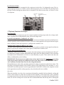
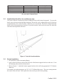
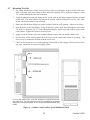
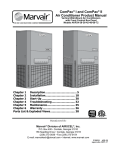
ComPac® I and ComPac® II Air Conditioner Product Manual Vertical Wall-Mount Air Conditioners with Front Control Box Panel Models AVPC 24-30-36-42-48-60-72 R-407c Chapter 1 Description............................ 5 Chapter 2 Installation.......................... 18 Chapter 3 Start-Up.............................. 30 Chapter 4 Troubleshooting.................. 31 Chapter 5 Maintenance........................ 34 Chapter 6 Warranty............................. 35 Parts List & Exploded Views.................... 36 Manufactured By: Marvair® Division of AIRXCEL™, Inc. P.O. Box 400 • Cordele, Georgia 31010 156 Seedling Drive • Cordele, Georgia 31015 (229) 273-3636 • Fax (229) 273-5154 E-mail: [email protected] • Internet: www.marvair.com P/01782 5.2011 How To Use This Manual This manual is intended to be a guide to Marvair's ComPac® line of vertical air conditioners. It contains installation, troubleshooting, maintenance, warranty, and application information. The information contained in this manual is to be used by the installer as a guide only. This manual does not supersede or circumvent any applicable national or local codes. If you are installing the ComPac® unit, first read Chapter 1 and scan the entire manual before beginning the installation as described in Chapter 2. Chapter 1 contains general, descriptive information and provides an overview which can speed up the installation process and simplify troubleshooting. If a malfunction occurs, follow this troubleshooting sequence: 1. Make sure you understand how the ComPac® unit works (Chapter 1). 2. Identify and correct installation errors (Chapter 2). 3. Refer to the troubleshooting information in Chapter 4. If you are still unable to correct the problem, contact the Factory at 1-800-841-7854 for additional assistance. Please read the following “Important Safety Precautions” before beginning any work. Important Safety Precautions 1. USE CARE when LIFTING or TRANSPORTING equipment. 2. TRANSPORT the UNIT UPRIGHT. Laying it down on its side may cause oil to leave the compressor and breakage or damage to other components. 3. TURN ELECTRICAL POWER OFF AT THE breaker or fuse box BEFORE installing or working on the equipment. LINE VOLTAGES ARE HAZARDOUS or LETHAL. 4. OBSERVE and COMPLY with ALL applicable PLUMBING, ELECTRICAL, and BUILDING CODES and ordinances. 5. SERVICE may be performed ONLY by QUALIFIED and EXPERIENCED PERSONS. * * * * Wear safety goggles when servicing the refrigeration circuit Beware of hot surfaces on refrigerant circuit components Beware of sharp edges on sheet metal components Use care when recovering or adding refrigerant 6. Use COMMON SENSE - BE SAFETY-CONSCIOUS This is the safety alert symbol . When you see this symbol on the ComPac unit and in the instruction manuals be alert to the potential for personal injury. Understand the signal word DANGER, WARNING and CAUTION. These words are used to identify levels of the seriousness of the hazard. ! DANGER Failure to comply will result in death or severe personal injury and/or property damage. ! WARNING Failure to comply could result in death or severe personal injury and/or property damage. ! CAUTION Failure to comply could result in minor personal injury and/or property damage. IMPORTANT is used to point out helpful suggestions that will result in improved installation, reliability or operation. SPECIFICATIONS SUBJECT TO CHANGE WITHOUT NOTICE. © 5.2011 Marvair® Div. Airxcel™, Inc. 2 ComPac 5.2011 WARNING • If the information in these instructions are not followed exactly, a fire may result causing property damage, personal injury or loss of life. • Read all instructions carefully prior to beginning the installation. Do not begin installation if you do not understand any of the instructions. • Improper installation, adjustment, alteration, service or maintenance can cause property damage, personal injury or loss of life. • Installation and service must be performed by a qualified installer or service agency in accordance with these instructions and in compliance with all codes and requirements of authorities having jurisdiction. INSTALLER: .Affix the instructions on the inside of the building adjacent to the thermostat. END USER: .Retain these instructions for future reference. Table of Contents Chapter 1ComPac® A/C Description & Specifications 1.1 General Description..................................................................................................................................5 1.2 Model Identification..................................................................................................................................6 1.3 Serial Number Date Code.........................................................................................................................6 1.4 Air Flow, Weights and Filter Sizes............................................................................................................6 1.5 General Operation...................................................................................................................................10 1.6 Electronic Control Board Mode of Operation.........................................................................................10 1.7 Optional Controls....................................................................................................................................12 1.8 Electrical Operation................................................................................................................................14 1.9 Economizer Components........................................................................................................................17 Chapter 2 Installation 2.1 Equipment Inspection..............................................................................................................................18 2.2 Installation Requirements........................................................................................................................18 2.3 Installation Materials . ...........................................................................................................................19 2.4 Porting and Duct Work . .........................................................................................................................21 2.5 Fresh Air Hood Installation . ..................................................................................................................22 2.6 Bracket Installation ................................................................................................................................22 2.7 Mounting the Unit ..................................................................................................................................23 2.8 Electrical Connections............................................................................................................................24 Chapter 3 Start-Up 3.1 Check-Out of Cooling Cycle . ................................................................................................................30 3.2 Check-Out of Heating Cycle...................................................................................................................30 Chapter 4 Troubleshooting 4.1 Overview.................................................................................................................................................31 4.2 Failure Symptoms Guide.........................................................................................................................31 4.3 Compressor Troubleshooting..................................................................................................................32 4.4 Control Board Diagnosis.........................................................................................................................33 3 ComPac 5.2011 Table of Contents Chapter 5 Maintenance 5.1 Scheduled Maintenance..........................................................................................................................34 Chapter 6 Warranty 6.1 Limited Product Warranty.......................................................................................................................35 Parts List and Exploded Views......................................................................................................................36 Illustrations Figure 1a. 1b. 1c. Figure 2a. 2b. Figure 3. Figure 4. Figure 5. Figure 6a. Figure 6b. Figure 6c. Figure 6d. Dimensional Data - Models AVP24/30/36 ComPac® A/C.....7 Dimensional Data - Models AVP42/48/60................................................................................ 8 Dimensional Data - Models AVP72 ComPac ® A/C................................................................ 9 Typical Electrical Schematic - Model AVP ComPac® I A/C.................................................. 15 Typical Electrical Schematic - Model AVP ComPac® II A/C................................................ 16 H205A Temperature Control Points........................................................................................ 17 Fresh Air Hood Installation..................................................................................................... 22 Wall Mounting Detail.............................................................................................................. 23 Humidistat Wiring Details....................................................................................................... 27 Thermostat Connection Diagram............................................................................................ 27 LL357D4 Wiring Detail.......................................................................................................... 28 CommStat™ 3 Wiring Detail.................................................................................................. 29 Tables Table 1 Table 2 Table 3 Table 4 Table 5 Table 6 CFM @ External Static Pressure.............................................................................................. 6 Ship Weight............................................................................................................................... 6 Standard Filter Size................................................................................................................... 6 Minimum Clearances.............................................................................................................. 19 Voltage Limitations................................................................................................................. 19 Maximum Static Pressure....................................................................................................... 22 4 ComPac 5.2011 Chapter 1 Description & Specifications 1.1 General Description The Marvair® ComPac® I and ComPac® II air conditioners are designed to cool electronic and communication equipment shelters. The AVPC models use R-407c refrigerant and a unique combination of controls and components to operate in extremely cold and high ambient conditions. The series includes multiple sizes with nominal cooling capacities from 24,000 to 72,000 BTUH. Electric resistance heating are available in various wattages. Desert Duty package (ComPac I air conditioners only) The Desert Duty package is designed for operation in hot climates including the Middle East and the American Southwest in ambient temperatures from 32°F to 130°F (0°C to 54°C). Standard features of the Desert Duty package include a thermal expansion valve and a sealed condenser fan motor. Cabinet features include a slotted panel in the base pan that improves air flow and also provides access to the compressor and condenser fan motor. Extreme Duty package (ComPac I and ComPac II air conditioners) The Extreme Duty package allows operation of the ComPac I air conditioners in ambient temperatures from 0°F to 130°F (-18°C to 54°C) and of the ComPac II air conditioners with the factory installed economizer from -20°F to 130°F (-29°C to 54°C). Note: operational temperatures are dependent on ambient conditions and the return air temperature. The Extreme Duty Package includes a suction line accumulator, thermal expansion valve (TXV), crankcase heater, hard start kit, an auto reset high pressure switch and an outdoor thermostat and fan cycle switch. The fan cycle control is standard on all ComPac air conditioners and operates based upon the liquid line pressure. The outside thermostat opens whenever the outside temperature is below 50°F (10°C) and closes when the outside temperature is 50°F (10°C) or higher. Whenever the temperature is below 50°F (10°C), the fan cycle switch is in the circuit; when temperatures are 50°F (10°C) or higher, the fan cycle switch is not in the circuit. The outdoor thermostat is used with a TXV to prevent excessive cycling or “hunting” of the TXV. ComPac II air conditioners with the economizer The economizer provides temperature control, energy savings, and increased reliability by decreasing the run time of the compressor and condenser fan. When the outside air is cool and dry, the economizer uses outside air to cool the shelter. Integral pressure relief allows the outside air to enter the shelter while permitting the indoor air to exit through the air conditioner. To insure proper operation and optimum performance, all economizers are non-removable, factory installed and tested. In addition, factory and field installed accessories can be used to meet specific requirements. The ComPac® I and ComPac® II air conditioners are manufactured and tested to UL Standard 1995, 2nd Ed. and CAN/CSA C22.2 No. 236-95, 2nd Ed. The AVPC models are commercial units and not intended for residential use. 5 ComPac 5.2011 1.2 Model Identification The model identification number is found on the data sticker. Rating plate located on side panel. ••• C • AC • • • • Refrigerant C = R-407c Nominal Cooling 24 = 24,000 BTUH 30 = 30,000 BTUH 36 = 36,000 BTUH 42 = 42,000 BTUH 48 = 48,000 BTUH 60 = 60,000 BTUH 72 = 72,000 BTUH Model AVP 1.3 Special Option Code R = Electric Reheat U = Scroll Comp. Power Supply A = 208/230V,1ø,60Hz C = 208/230V,3ø,60Hz D = 460V,3ø,60Hz E = 380V, 3ø, 50Hz W = 220/240V, 1ø, 50Hz Configuration N = ComPac® I A/C C = ComPac® II A/C D =Desert Duty (ComPac I Units Only) E = Extreme Duty (ComPac II Units Only) System Type Air Conditioner Electric Heat – 000 = No Heat 040 = 4 kW 050 = 5 kW 080 = 8 kW kW 090 100 120 150 = = = = 9 kW 10 kW 12 kW 15 kW Serial Number Date Code A = January B = February C = March D = April E = May F = June G = July H = August J = September K = October L = November M = December 1.4 Air Flow, Weights and Filter Sizes L = 2000 M = 2001 N = 2002 P = 2003 R = 2004 S = 2005 T = 2006 U = 2007 V = 2008 Y = 2009 Z - 2010 A = 2011 MODEL 0.10 0.15 0.20 0.25 0.30 0.40 0.50 AVP24 860 825 810 740 670 N/A N/A AVP30 1100 1050 1000 960 920 810 N/A AVP36 1310 1265 1220 1185 1150 1060 N/A AVP42 N/A N/A 1650 1585 1520 1450 1360 AVP48 N/A N/A 1900 1830 1760 1700 1620 AVP60 N/A N/A 1900 1830 1760 1700 1620 AVP72 N/A N/A 2100 1950 1800 1730 1660 Air flow ratings of 208-230 volt units are at 230v. Air flow ratings of 460 volt units are at 460 volts. Operation of units at a voltage different from the rating point will affect air flow. Table 1. CFM @ External Static Pressure (Wet Coil) (IWG) POUNDS/KG MODEL COMPAC® I A/C COMPAC® II A/C LBS/KG AVP24 274/125 286/130 LBS/KG AVP30/36 355/160 365/170 LBS/KG AVP42 495/225 527/240 LBS/KG AVP48 521/240 552/250 LBS/KG AVP60 535/245 565/260 LBS/KG AVP72 625/284 640/290 Table 2. Ship Weight MODEL FILTER SIZE (inches) FILTER SIZE (mm) *Two filters required. AVP24 16 x 25 x 2 406 x 635 x 51 AVP30/36 16 x 30 x 2 406 x 762 x 51 AVP42/48/60 22 x 36-1/2 x 2 559 x 927 x 51 AVP72 18 x 24 x 2* 452 x 610 x 51 Table 3. Filter Size 6 ComPac 5.2011 Figure 1a. Dimensional Data - Models AVP24/30/36 ComPac® Air Conditioner L.H. SIDE MODEL IN MM IN MM A 39-3/8 1000 44-9/16 1132 FRONT AIR OUTLET D 8 203 8 203 E 20-1/2 521 18 457 1.500 FLANGE WIDTH F 12 305 14 356 R.H. SIDE AIR INLET 0 4.188 3-9/16” (91mm) 1-1/16” (27mm) 0.000 4-9/16” (116mm) 5/8” (16mm) 0.000 34-5/8” (879mm) 26-1/8” (664mm) 30-3/8” (772mm) 35-1/4” (895mm) 17-5/8” (448mm) 21-7/8” (556mm) 9-1/8” (232mm) 13-3/8” (340mm) 5/8” (16mm) 4-7/8” (124mm) 0 Ø 3/8” (10mm) TYP 5-17/32” (140mm) G 27-3/4 705 28-1/2 724 H 20 508 28 711 19 mm 43 mm 89 mm BACK 3-9/16” (91mm) 1-1/16” (27mm) 1-5/8” (41mm) Ø 3/8” (10mm) TYP 4-3/16” (106mm) M 37-7/8 962 43-1/16 1094 660 mm *H DIM IS CENTERED BETWEEN A DIM AVP30/36 AVP24 BOTTOM MOUNTING BRACKET BOTTOM MOUNTING BRACKET AVP30-36 AVP24 4-3/16” (106mm) 1-5/8” (41mm) 922 mm 1753 mm 10-7/16” (265mm) AIR INLET 1816 mm SIDE FRESH AIR VENTS ONLY ON UNITS WITH VENTILATION CONFIGURATIONS "C", "B", "Y", & "Z" HEATER ACCESS 20-1/4” (514mm) 15-11/32” (390mm) 43 mm CIRCUIT BREAKER ACCESS 22 mm 30-1/16” (764mm) 81 mm M C/C MOUNTING HOLES 25-5/32” (639mm) 17.00 432 mm DIMENSIONS - AVP 24-36 39-7/8” (1013mm) 7 34-31/32” (888mm) 40-1/2” (1029mm) ComPac 5.2011 51 mm 413 mm 413 mm 413 mm 413 mm Figure 1b. Dimensional Data - Models AVP42/48/60 ComPac® Air Conditioner 8 ComPac 5.2011 AVP42-60 MODEL IN MM B C D E F 117 mm 38 mm 57 mm G R.H. SIDE H 502 mm I 1054 mm J 502 mm K SIDE FRESH AIR VENTS ONLY ON UNITS WITH VENTILATION CONFIGURATIONS "C", "B", "Y", & "Z" 10 mm 45-1/8 22-5/8 86.00 10.00 30.00 16.00 26-1/2 30.00 1-5/16 40-9/16 38-9/16 1146 575 2184 254 762 406 673 762 33 1030 979 A FRONT 3/4” (19 mm) 19 mm x 25 mm 51 mm DIMENSIONS - AVP 42-60 M N O P 1-1/2” 38 mm 152 mm 610 mm Q 1067 mm R 1-1/8 43-1/2 32-3/8 30-3/8 1-1/4 83-5/16 1-3/4 29 1105 822 772 32 2118 44 L BACK 19 mm x 25 mm 1981 mm 1524 mm 10 mm Figure 1c. Dimensional Data - Model AVP72 ComPac® I & ComPac® II Air Conditioners 9 ComPac 5.2011 1.5 General Operation Refrigerant Cycle (Cooling Mode) The ComPac® I & ComPac® II A/C use R-407c refrigerant in a conventional vapor-compression refrigeration cycle to transfer heat from air in an enclosed space to the outside. A double blower assembly blows indoor air across the evaporator. Cold liquid refrigerant passing through the evaporator is boiled into gas by heat removed from the air. The warmed refrigerant gas enters the compressor where its temperature and pressure are increased. The hot refrigerant gas condenses to liquid as heat is transferred to outdoor air drawn across the condenser by the condenser fan. Liquid refrigerant is metered into the evaporator through capillary tubes to repeat the cycle. Heating Mode A wall-mounted thermostat controls the heating cycle of models which incorporate resistance heating elements. On a call for heat, the thermostat closes the heat relay to energize the indoor fan and the resistance elements. Except on units with the optional dehumidification kit, the compressor is locked out during the heating cycle. Economizer Operation (ComPac® II A/C Only) The economizer is a regulated damper system with controls. The damper regulates the circulation of outside air into the enclosure (when the outdoor air conditions are suitable) to reduce the need for mechanical cooling, save energy, and extend compressor life. Depending upon the options selected, the damper responds to the enthalpy of the outdoor air. On a call for cooling from a space thermostat, it operates as follows: When the enthalpy of the outdoor air is below the set point, the outdoor air damper is proportionally open (and return air damper is proportionally closed) to maintain between 50°F and 56°F (10°C to 13°C) at the mixed/discharge air sensor. Integral pressure relief allows the indoor air to exit the shelter through the air conditioner. When the enthalpy of the outdoor air is above the set point, the outdoor air damper closes to its minimum position. A call for cooling from the space thermostat brings on mechanical cooling. An optional built-in adjustable minimum position potentiometer (part number 70012) controls the amount of outdoor air admitted to meet minimum ventilation requirements. 1.6 Electronic Control Board Mode of Operation Normal 24 VAC power must be continuously applied to “R” and “C”. Upon a call for cooling “Y” and with the high pressure switch (HPS) closed, the compressor will be energized. (Note: See the delay on make feature.) The compressor will remain energized during the 3 minute timed low pressure by-pass cycle. If the low pressure switch (LPS) is open after the 3 minute by-pass cycle, the compressor will de-energize. Lock-out If either of the fault conditions (LPS or HPS) occurs twice during the same call for cooling, the control board will enter into and indicate the lockout mode. In the lockout mode, the compressor is turned off. If there is a call for indoor air flow “G”, the blower remains energized, the alarm output is energized and the status led will blink to indicate which fault has occurred. When the lockout condition is cleared, the unit will reset if the demand for the thermostat is removed or when the power is reset. With the control board, the user can now have either normally closed or normally open contacts by moving a wire on the control board. The ComPac® air conditioners are factory wired to be normally open. 10 ComPac 5.2011 Delay on Break If the compressor is de-energized due to a loss of a cooling “Y” call or the first fault, the unit re-start will be delayed 3 minutes from the time the contactor is de-energized. (Note: There is no delay on break if the lockout condition is reset.) Delay on Make On initial power up only, the unit will wait 0.03 to 10 minutes from the cooling “Y” call before allowing the contactor to energize. The delay can be adjusted by the DOM wheel on the board. Factory recommended wait is 3 minutes. Low Pressure By-Pass Time When starting, the low pressure switch (LPS) fault condition will be by-passed for 3 minutes before the contactor is de-energized. Post Purge Upon a call for indoor airflow “G” the blower will energize immediately. When in the cooling mode, the blower will remain energized for 10 to 90 seconds (adjustable) after the compressor has been de-energized. The time period can be changed by fan purge wheel on the board. Factory setting is 90 seconds. LED Indicator Lights COLOR Green Red Red Red TYPE Power Status Status Status STATUS Contstant On Contstant On 1 Blink 2 Blinks DESCRIPTION 24 VAC power has been applied Normal operation High pressure switch has opened twice Low pressure switch has opened twice Low Ambient Control The low ambient control permits cooling when outdoor ambient temperatures are low. The control uses a reverse-acting high pressure switch to cycle the condenser fan motor according to liquid refrigerant pressure conditions. Switch closure and fan operation occurs when the pressure reaches 250 PSIG. The switch opens again when the refrigerant pressure falls to 190 PSIG. Therefore, the outdoor fan always starts after the compressor, and it will cycle frequently during normal operation at low outdoor conditions. On ComPac air conditioners with the Extreme Duty package, an outside thermostat opens whenever the outside temperature is below 50°F (10°C) and closes when the outside temperature is 50°F (10°C) or higher. Whenever the temperature is below 50°F (10°C), the fan cycle switch is in the circuit; when temperatures are 50°F (10°C) or higher, the fan cycle switch is not in the circuit. The outdoor thermostat is used with a TXV to prevent excessive cycling or “hunting” of the TXV. High Pressure Switch The high pressure switch is mounted on the compressor discharge line. It is electrically connected to a lockout relay which shuts down the system if the refrigerant pressure rises to 450 PSIG. This protects the unit if airflow through the condenser is blocked or if the outdoor fan motor fails. Although the contacts of the high pressure switch close when the refrigerant pressure falls to approximately 300 PSIG, the system must be manually reset once the lockout relay is activated. A manual reset is necessary to prevent harmful short-cycling. To reset switch, turn primary power off, then back on or turn thermostat system switch off, then back on. 11 ComPac 5.2011 Low Pressure Switch The low pressure switch is mounted on the compressor suction line. It is designed to open if the refrigerant pressure drops to 35 PSIG; it resets when the pressure rises to 60 PSIG. The switch protects the unit if airflow through the indoor blower is impeded, if the blower motor fails, or if there is a loss of refrigerant. POST PURGE WHEEL LEDs DELAY ON MAKE (COMPRESSOR TIME DELAY) WHEEL 1.7Optional Controls & Packages Hard Start Kit Used on single phase equipment to give the compressor higher starting torque under low voltage conditions. Generally not recommended on units with scroll compressors. Coastal Environmental (ComPac® I A/C Only) Recommended for units to be installed near an ocean or on seacoast. Includes corrosion resistant fasteners, sealed or partially sealed condenser fan motor, protective coating applied to all exposed internal copper in the condenser section and a protective coating on the condenser coil. Stainless Steel Cabinet (ComPac® I A/C Only) The units can be constructed with stainless steel exterior panels or with the exterior panels and interior panels (except for the condenser fan venturi panel) constructed of stainless steel. Electric Reheat Dehumidification A humidity controller (p/n 50057) allows electric heat and cooling to operate simultaneously. Marvair® air conditioners equipped with the dehumidification option allow the indoor humidity of the controlled environment to be maintained at or below a certain humidity set point. These units do not have the ability to add humidity to the building. IMPORTANT: The electrical wire and breaker or fuses must be sized for simultaneous operation of the electric heater and the air conditioner. Refer to the data sticker on the unit or the ComPac® Air Conditioner Product Data Sheet for the sizing information. Dehumidification is achieved by operating mechanical cooling in conjunction with electric reheat. The strip heat is sized approximately to the sensible capacity of the total tonnage of the machine (i.e., on a 24,000 BTU unit the strip heat is sized at approximately 20,000 BTU). Because the strip heat is sized to the approximate sensible cooling capacity, only selected models are available. Operation: When the humidity rises above the set point on the humidity controller both mechanical cooling and electric reheat operate to temper the air and lower the humidity. If the temperature in the controlled environment rises above the set point of the thermostat and the unit is operating in the dehumidification mode, the call for cooling will override the call for dehumidification and the strip heat is disengaged 12 ComPac 5.2011 until the thermostat is satisfied. This assures the environment temperature is maintained as first priority and humidity control is second. In applications where a shelter has redundant air conditioning units and is controlled by a lead lag controller (Marvair's LL357D4 or CommStat3 Controller), most times the dehumidification option is only necessary on one of the two units. It is possible for one unit to be operating in the cooling mode while the unit with dehumidification is operating at the same time. If the cooling unit does not maintain the shelter temperature set point, the unit with dehumidification will go into the cooling mode. It does not matter whether the unit with dehumidification is the lead or lag unit. Dirty Filter Indicator A diaphragm type of indicator measures the air pressure on either side of the filter and when the pressure drops below the set point, a red LED is illuminated. The set point is adjustable. Minimum Potential Potentiometer Used in the ComPac® II units with the factory installed economizer. The potentiometer prevents the economizer from closing completely, assuring that outside air will be brought into the shelter and exhausted whenever the indoor blower is operating. This prevents negative pressurization of the building. The minimum potential potentiometer is adjustable. Protective Coil Coatings Two coil coatings are offered. Either the condenser or evaporator coil can be coated, however, coating of the evaporator coil is not common. For harsh conditions, e.g., power plants, paper mills or sites were the unit will be exposed to salt water, the coil should be coated with either an impregnated polyurethane (trade name BlyGold®). The impregnated polyurethane coatings is sprayed on and passes 3,000 hours of B117 salt fog test. Note: Cooling capacity may be reduced by up to 5% on units with coated coils. Factory Installed Disconnects on 380V Units Factory installed disconnects are standard on all 208-230v. and 460 volt units. As an option, all 380V. units may be ordered with a disconnect. Phase Monitor and High and Low Voltage Detector Can be used on all 3Ø scroll compressors. Detects if the unit is properly phased and if proper voltage is present. If it is not, it will not allow the compressor to operate. See Phase Monitor Technical Bulletin for complete details. Right & Left Side Compressor Configuration The air conditioners can be built with the compressor on the opposite side to facilitate service access when two units are installed side by side. In the 24-30-36, the standard location for the compressor is on the right hand side. In the 42-48-60, the standard location for the compressor is on the left hand side. In the 72, the compressor is accessed from the front of the unit and an opposing configuration is not required. Compressor Sound Jacket Reduces compressor sound levels. Constructed of 0.75 lb density loaded vinyl with an acoustical nonwoven sound absorber. Washable Return Air Filters No Outside Air (ComPac I air conditioner only) For operation in dusty areas, the unit can be built without the outside air damper. 13 ComPac 5.2011 1.8Electrical Operation The compressor and condenser fan are energized with a contactor controlled by a 24 VAC pilot signal. Some compressors incorporate an internal PTC crankcase heater that functions as long as primary power is available. The heater drives liquid refrigerant from the crankcase and prevents loss of lubrication caused by oil dilution. Power must be applied to the unit for 24 hours before starting the compressor. The condenser (outside fan) motor is energized by the same contactor. However, the motor is cycled on and off by the low ambient control (see low ambient control 1.6). The indoor evaporator fan motor is controlled by the fan purge on the electronic control board. 14 ComPac 5.2011 Figure 2a. Typical Electrical Schematic - ComPac® I A/C 15 ComPac 5.2011 Figure 2b. Typical Electrical Schematic - ComPac® II A/C 16 ComPac 5.2011 1.9 Economizer Components (ComPac® II A/C Only) Damper Actuator: The damper actuator is a 24V motor that modulates the position of the damper blade. It is capable of driving a full 90 degrees within 90 seconds. The assembly has a spring return to close the damper during power outage. Controls: The economizer is controlled by the H205A enthalpy control. H205A Economizer Changeover Control: The H205A enthalpy controller responds to the total heat content of the outdoor air to provide changeover to outside air for free cooling. The change point (factory set at "D") is adjustable from 53°F (12°C) @ 50% RH (full counterclockwise) to 78°F (26°C) @ 50% RH (full clockwise). Refer to Figure 3. Once the H205A has selected outside air, the mixed air sensor will limit the air temperature delivered to the space by modulating the damper blade to "mix in" a quantity of inside air to provide a constant 50° to 56°F. (Adjustable minimum potentiometer, part number 70012, is optional.) The controller modulates the position of the outside air damper in response to input from the enthalpy and mixed air sensors. The controller is designed to maintain the supply air temperature between 50° to 56°F (10°C to 13°C) by mixing warm indoor air with cooler outdoor air. On a call for cooling from the wall-mounted thermostat, if outdoor conditions are suitable, the controller will open the damper and admit outside air (i.e., economizer cooling). If the outdoor ambient is too hot or humid, the controller will place the actuator in the closed or minimum open position and activate mechanical cooling. The compressor is locked out during the economizer cooling mode. Mixed Air Sensor: The mixed air sensor is a thermistor mounted on a bracket adjacent to the right side of the blower assembly. The thermistor senses the air temperature entering the structure, and provides a signal to the economizer controller for modulating the position of the damper. Nominal resistance of the sensor at 77° F (26°C) is 3000 ohms. CONTROL CONTROL POINT* CURVE AT 50% RH A 72°F/23°C B 68°F/20°C C 63°F/17°C D 58°F/14.5°C Full CCW is 55°F *Approximate Deg. Figure 3. H205A Temperature Control Points 17 ComPac 5.2011 Chapter 2 Installation WARNING Failure to observe and follow Warnings and Cautions and these Instructions could result in death, bodily injury or property damage. Read this manual and follow its instructions and adhere to all Cautions and Warnings in the manual and on the Marvair unit. 2.1 Equipment Inspection Concealed Damage Inspect all cartons and packages upon receipt for damage in transit. Remove cartons and check for concealed damage. Important: keep the unit upright at all times. Remove access panels and examine component parts. (Note: the "L"-shaped bottom bracket is stored in the condenser air compartment. Remove it before replacing the side screen). Inspect refrigerant circuit for fractures or breaks. The presence of refrigerant oil usually indicates a rupture. If damage is apparent, immediately file a claim with the freight carrier. Units that have been turned on their sides or tops may have concealed damage to compressor motor mounts or to the oil system. If the unit is not upright, immediately file a claim for concealed damages and follow these steps: 1. Set unit upright and allow to stand for 24 hours with primary power turned on. 2. Attempt to start the compressor after 24 hours. 3. If the compressor will not start, makes excessive noise, or will not pump, return the unit to the freight carrier. 2.2 Installation Requirements General 1. Inspect unit for completeness. Check for missing parts (e.g. hardware). Refer to the installation kit information in section 2.3. 2. Remove access panels and check for loose wires. Tighten screw connections. 3. Complete and mail the warranty registration card. You must consider all of the following when choosing the installation site: 1. Noise. Install the unit so that the least amount of noise will be transmitted to inhabited spaces. 2. Condensate Drainage. Condensate produced during operation must be discharged to a suitable drain. 3. Placement. A) Place the unit in a shaded area, if possible. B) Install it above ground for protection against flooding. C) The unit exhausts air. Be sure that the airflow is not impeded by shrubbery or other obstructions. D) When installing multiple units, please note the recommended clearances noted in Table 4. 4. Airflow Requirements: Note the minimum CFM requirements (Table 6). Keep duct lengths as short as possible. Do not obstruct airflow through the unit. Duct work should be designed and installed in accordance with all applicable safety codes and 18 ComPac 5.2011 standards. Marvair® strongly recommends referring to the current edition of the National Fire Protection Association Standards 90A and 90B before designing and installing duct work. The duct system must be engineered to insure sufficient air flow through the unit to prevent over-heating of the heater element. This includes proper supply duct sizing, sufficient quantity of supply registers, and adequate return and filter areas. Duct work must be of correct material and must be properly insulated. Duct work must be constructed of galvanized steel with a minimum thickness of .019 inches. Duct work must be firmly attached, secured, and sealed to prevent air leakage. See section 2.4 for additional duct work requirements. 5. Clearances: Note the minimum clearances required for proper operation and service. MIN. CLEARANCE AROUND SIDES (SINGLE UNIT) MIN. CLEARANCE BETWEEN UNITS (TWO UNITS) MIN. SPACE ABOVE UNIT 24 30 inches (76 cm) 18 inches (46 cm) 24 inches (61 cm) 30/36 30 inches (76 cm) 18 inches (46 cm) 24 inches (61 cm) 42/48/60 30 inches (76 cm) 30 inches (76 cm) 24 inches (61 cm) 72 30 inches (76 cm) 30 inches (76 cm) 12 inches (31 cm) MODEL Table 4. Minimum Clearances 6. Codes: Make sure your installation conforms to all applicable electrical, plumbing, building, and municipal codes. Some codes may limit installation to single story structures. 7. Electrical Supply: The power supply must have the appropriate voltage, phase, and ampacity for the model selected. Voltage must be maintained above minimum specified values listed below. Refer to the data sticker on the unit for ampacity requirements. Electrical Rating Designations* A C D E W 208/230 208/230 460 380 220-240 1 3 3 3 1 Minimum Voltage 197 197 414 342 198 Maximum Voltage 253 253 506 418 264 Nominal Voltage Phase * Letters refer to model number code designations. Refer to page 6. Table 5. Voltage Limitations 2.3 Installation Materials Installation Kits The ComPac® I and ComPac® II A/C units are shipped with one 12 Ga. "L" shaped bottom bracket. If you have not yet unpacked the unit, follow the instructions in section 2.1. All units have built-in full length mounting flanges. Therefore, use of mounting brackets is not required. Kit Components: 1. One 12 Ga. "L"-shaped bottom bracket Accessories: The package may include other factory-supplied items (optional) as follows on the next page: 19 ComPac 5.2011 P/N Description S/04581 CommStat 3 Controller, Solid State Lead/Lag Controller S/07846 CommStat 4 Controllers, Solid State Lead/Lag Controller S/07529 LL357D4, Lead/Lag Controller with T'stat & Sub-Base; Controls 2 A/C Units 50123 Digital thermostat. 1 stage heat, 1 stage cool. 7 day programmable. Fan switch: Auto & On. Auto-change over. Keypad lockout. Non-volatile program memory. 50107 Digital thermostat. 2 stage heat, 2 stage cool. 7 day programmable. Fan switch: Auto & On. Auto-change over. Status LED’s. Backlit display. Programmable fan. Non-volatile program memory. 80674 20 x 8" Adjustable, Aluminum, Double Deflection Supply Grill for AVP24 28 x 8" Adjustable, Aluminum, Double Deflection Supply Grill for AVP30-36 30 x 10" Adjustable, Aluminum, Double Deflection Supply Grill for AVP42-48-60-72 80675 80676 80677 80678 80679 20 x 12" Aluminum Return Grill for AVP24 28 x 14" Aluminum Return Grill for AVP30-36 30 x 16" Aluminum Return Grill for AVP42-48-60-72 Additional Items Needed: Additional hardware and miscellaneous supplies (not furnished by Marvair®) are needed for installation. For example, the list below contains approximate quantities of items typically needed for mounting a unit on a wood frame wall structure. Concrete or fiberglass structures have different requirements. ComPac® I and ComPac® II A/C (10) 3/8" carriage head mounting bolts for unit mounting flanges. The length needed is typically the wall thickness plus one inch. (20) 3/8" washers (10) 3/8" hex nuts (6) 3/8" x 2-1/2" lag screws for bottom bracket • Silicone Sealer to seal around cracks and openings • 4-conductor low voltage multicolored wire cable (i.e. thermostat wire) • Appropriate electrical supplies such as conduit, electrical boxes, fittings, wire connectors, etc. • High voltage wire, sized to handle the MCA (minimum circuit ampacity) listed on the data plate. • Over-Current Protection Device sized in accordance with the MFS (maximum fuse size) listed on the unit data plate. 20 ComPac 5.2011 Warning FIRE HAZARD Improper adjustment, alteration, service, maintenance or installation could cause serious injury, death and/or property damage. Installation or repairs made by unqualified persons could result in hazards to you and others. Installation MUST conform with local codes or, in the absence of local codes, with codes of all governmental authorities have jurisdiction. The information contained in this manual is intended for use by a qualified service agency that is experienced in such work, is familiar with all precautions and safety procedures required in such work, and is equipped with the proper tools and test instruments. 2.4 Porting and Duct Work General Information Note: The following instructions are for general guidance only. Due to the wide variety of installation possibilities, specific instructions will not be given. When in doubt, follow standard and accepted installation practices, or contact Marvair® for additional assistance. Wall Openings Measure the dimensions of the supply and return ports on the unit. Cut the openings in the exterior wall for the supply and return. IMPORTANT: All units with electric heat must have 1" (25.4mm) clearance on all four sides of the supply outlet duct flange on the unit. The 1" (25.4mm) clearance must extend on all sides of the supply duct for the first 3 feet (1 meter) from the unit. IMPORTANT: Marvair® requires a minimum of 1" (25.4mm) from the surface of any supply ducts to combustible material for the first 3 feet (1 meter) of the duct. Ducting Extensions should be cut flush with the inside wall for applications without duct work. Applications using duct work should be designed and installed in accordance with all applicable safety codes and standards. Marvair® strongly recommends referring to the current edition of the National Fire Protection Association Standards 90A and 90B before designing and installing duct work. The duct system must be engineered to insure sufficient air flow through the unit to prevent over-heating of the heater element. This includes proper supply duct sizing, sufficient quantity of supply registers, adequate return and filter area. Ductwork must be of correct material and must be properly insulated. Duct work must be constructed of galvanized steel with a minimum thickness of .019 inches for the first 3 feet (1 meter). Ductwork must be firmly attached, secured and sealed to prevent air leakage. Do not use duct liner on inside of supply duct within 4 feet (122cm) of the unit. Galvanized metal duct extensions should be used to simplify connections to duct work and grilles. Use fabric boots to prevent the transmission of vibration through the duct system. The fabric must be U.L. rated to a minimum of 197°F (92°C). Minimum Airflow Requirements The duct system must be engineered to assure sufficient air flow through the unit even under adverse conditions such as dirty filters, etc. Use Table 6 below and Table 1, CFM at External Static Pressure (Wet Coil) in section 1.4. 21 ComPac 5.2011 BASIC MODEL AVP24 AVP30/36 AVP42/48/60 AVP72 MAXIMUM TOTAL STATIC .30 .40 .50 .50 MINIMUM FILTER AREA 2.75 3.33 5.50 6.00 Table 6. Maximum Static Pressure (For units with 2" Pleated Filters) 2.5 Fresh Air Hood (ComPac I air conditioners only) The fresh air hood is located on the inside, behind the slots on the bottom front panel. To access the hood, remove the screws that hold the front panel. The air flow can be adjusted from no (0%) fresh air to approximately 15% of rated air flow of fresh air, in 5% increments. The hood is shipped from the factory in the closed position (no fresh air). To provide fresh air, remove the two screws on either side of the hood and reposition as desired.. Figure 4. Fresh Air Hood Installation 2.6 Bracket Installation 1. All models have built-in mounting flanges. 2. Apply a bead of silicone sealer on the wall side of the bottom support brackets on the unit. Circle the mounting holes with the silicone bead. 3. Refer to Figure 5. Attach the bottom support bracket to the wall using appropriate 3/8" diameter hardware. For example, on wooden structures, use 3/8" x 2-1/2" all-thread lag screws. The screws must penetrate the center of the wall stud. Drill a pilot hole in the stud to prevent it from splitting. 22 ComPac 5.2011 2.7 Mounting The Unit 1. For wiring into the back of unit, locate the lower of the two knockouts on the wall side of the unit. Drill a one inch hole in the shelter wall to match this opening. Allow sufficient clearance to run 3/4" conduit through the hole and to the unit. 2. Using an appropriate and safe lifting device, set the unit on the bottom support bracket mounted on the wall. You must stabilize the unit on the bracket with the lifting device or by some other means - the bracket alone is not sufficient. 3. Make sure that the duct flanges are properly aligned with the wall opening. Adjust as necessary. 4. Note the holes in each side flange. Using the holes for guides, drill holes through the wall with a 3/8" drill bit. Insert the 3/8" x 5" bolts through the flanges. Install nuts and washers on the inside of the shelter. Tighten the bolts to secure the unit. 5. Apply a bead of silicone where the mounting flange contacts the unit and the shelter wall. 6. On the inside of the shelter, install the wall sleeves in the supply and return air openings. The sleeves may be trimmed to fit flush with the inside wall. 7. Check the fit of each sleeve to its mating flange for possible air leaks. Apply silicone sealer to close any gaps. Install the air return and supply grilles. For units with electric heat, a one inch clearance is required around the duct extensions. The duct extensions must be constructed of galvanized steel with a minimum thickness of .019” as per the NFPA standards 90A & 90B. Figure 5. ComPac® I and ComPac® II A/C Wall Mount Detail 23 ComPac 5.2011 2.8 Electrical Connections WARNING ELECTRICAL SHOCK HAZARD Failure to follow safety warnings exactly could result in serious injury, death, and/or property damage. Turn off electrical power at fuse box or service panel BEFORE making any electrical connections and ensure a proper ground connection is made before connecting line voltage. Important All electrical work must meet the requirements of local codes and ordinances. Work should be done only by qualified persons. The ComPac® units may incorporate an internal crankcase heater for compressor protection. The crankcase heater must be energized for at least 24 hours prior to starting the compressor. Scroll compressors, like several other types of compressors, will only compress in one rotational direction. The direction of rotation is not an issue with single-phase compressors since they will always start and run in the proper direction. However, three phase compressors will rotate in either direction depending upon phasing of power. Since there is a 50-50 chance of connecting power in such a way as to cause rotation in the reverse direction, it is imperative to confirm that the compressor is rotating in the proper direction at the initial field start-up of the system. Verification of proper rotation is made by observing that the suction pressure drops and the discharge pressure rises when the compressor is energized. An alternate method of verification for self contained system with small critical refrigerant charges, where the installation of gauges may be objectionable, can be made by monitoring the temperature of the refrigerant lines at the compressor. The temperature should rise on the discharge line while the suction line temperature decreases. Reverse rotation also results in a substantially reduced current draw when compared to tabulated values. There is no negative impact on durability caused by operating three phase compressors in the reversed direction for a short duration of time, usually defined as less than one hour. However, after several minutes of operation the compressor's internal protector will trip. The compressor will then cycle on the protector until the phasing is corrected. Reverse operation for longer than one hour may have a negative impact on the bearings. High Voltage Wiring - (Single Units) The power supply should have the proper voltage, phase, and ampacity for the selected model. 1. Size the incoming power supply lines according to Code requirements. Run the power conductors through the knockouts on the wall side of the unit, or to those adjacent to the electrical control box. Use appropriate conduit and strain reliefs. 2. Connect the wires to the input side of the internal breaker or terminal block (L1 & L2 for singlephase units; L1, L2, & L3 for three-phase models). 3. Install the ground wire on the ground lug. 4. For units designed for operation on 208/230V, 60Hz and 220-240V, 50Hz power supply, the transformer is factory wired for a 230V power supply. For a 208V power supply, remove the orange lead from the transformer and connect the red lead. Insulate the orange lead. For units operating on a 200-220v power supply, the red lead is factory wired to the transformer. 5. 460V units have a step down transformer for 230V motors. 24 ComPac 5.2011 Dual Unit Phasing For applications where one controller operates two units, e.g., the CommStat 4 or LL357D. The LL357D4 and the LL357D3 do not require unit phasing. However, if other devices are connected to the control system, phasing of the air conditioner is required. Earlier models; i.e., LL357, LL357A, LL357D2 require the unit to be properly phased. 1. Wire each unit as described in steps 1 through 4 above. 2. Test for proper phasing as follows: A. Power up the units. B. Using an AC volt meter set to the 300 volt scale, measure voltage between terminal L1 on the compressor contactor of unit #1 and terminal L1 on the compressor contactor of unit #2 If voltage is present, units are wired out of phase and must be rewired. C. If units are not in phase, turn off power and reverse the field power leads connected to the internal circuit breaker on one of the units only. D. Restore power and retest the phase (step B). When the voltage reads "0", the units are in phase. E. Turn off power and proceed. Low Voltage Wiring IMPORTANT. The following instructions are generic wiring instructions and may not be applicable for air conditioners with various options. Always refer to the wiring diagram in the air conditioner for the proper method to wire your unit. 1. On single units, pull the low voltage wiring (e.g., 18 gauge 4-conductor Class 2 thermostat wire) from the ComPac® A/C into the thermostat / subbase assembly. See Figure 6b for connections to various thermostats. 2. Mount the thermostat on the wall of the shelter. The thermostat should be located so that the supply air from the unit does NOT blow directly on to the thermostat. Connect the thermostat to the terminal block in the ComPac air conditioner as shown in Figures 6a and 6b. 3. On dual units, refer to the Marvair® LL357D4 Lead/Lag Controller Specification Sheet or CommStat 4 Controller Specification sheet. Level and install the LL357D4 or CommStat 3 subbase. Wire the two ComPac® units to the Lead/Lag Controller, according to the wiring diagram on the specification sheet and as shown in Figure 6c or 6d (note: the diagram also appears on the back cover of the controller). Remote Signalling: Terminals 5 & 7(N.O.) and 6 & 7 (N.C.) on the ComPac® A/C terminal board are dry contacts which can be used for remote signalling in the event of a/c cutoff on low or high pressure limit. Continuous fan operation: For continuous indoor fan operation on single units, install a jumper between terminals 8 and 3. For continuous indoor fan operation on dual units using the LL357D4, install jumper between 8 and 3 and remove jumper between 1 and 3. CommStat 3 Controller (See Figure 6d) The CommStat 3 Controller by Marvair® is a solid state control package designed to operate a fully or partially redundant air conditioning system for a telecommunication cabinet or shelter. The CommStat 3 Controller is factory programmed with standard industry set points to facilitate installation. If desired, each of the set points can be quickly and easily changed in the field by the installer. It can be used with Marvair’s ComPac® I or II unique vertical packaged wall mount air conditioners or Marvair’s 25 ComPac 5.2011 environmental control units. See CommStat 3 Product Data Sheet for installation and programming instructions. LL357D4 Lead/Lag Controller (See Figure 6c) The Marvair® LL357D4 is a complete control package designed to operate a fully or partially redundant air conditioning system. It consists of a two-stage heat and two-stage cool electronic thermostat and a solid state timer. It can be used with either the Marvair ComPac® I vertical packaged wall mount air conditioner or our unique ComPac® II air conditioner with built-in economizer. The LL357D4 provides environmental control and the security demanded by the communication shelter industry for a backup unit. The lead/lag controller insures equal wear on both air conditioners while allowing the lag unit to assist upon demand. The LL357D4 is factory wired, tested, and mounted in an enclosure for quick installation. Refer to the LL357D4 Product Data Sheet for complete installation instructions. Operational Specifications • Thermostat Range: 45ºF to 90ºF (7ºC to 32ºC) • Accuracy: ±1ºF (± ½ºC) • Changeover Temperature Differential (separation between the heat set point and the cool set point): 2ºF to 9ºF (1.0ºC to 4.5ºC) • First Stage Temperature Differential (number of degrees between the set point temperature and the “turn on” temperature): 1ºF to 3ºF (.5ºC to 1.5ºC) • Second Stage Temperature Differential (number of degrees between when stage 1 turns on and when stage 2 turns on): 1ºF to 6ºF (.5ºC to 3.0ºC). • Minimum Cool Temperature Set Point: Adjustable from 45ºF to 75ºF (7ºC to 24.0ºC). • Maximum Heat Temperature Set Point: Adjustable from 55ºF to 90ºF (13ºC to 32.0ºC) • Staged OFF Outputs: Air conditioners will turn off independently. Timing Device • Solid state timer with both 3.5 and 7 day changeover capability. NOTE: Cut timer circuit wire to provide 3.5 day changeover. Timing accuracy ±5%. • Momentary push button for accelerated manual timer advance. (9 seconds = 7 days) • Light emitting diode indicates power on and identifies the lead unit. Unit Shutdown/Fire Alarm Systems Immediate shutdown of the air conditioning system can be accomplished by wiring the normally closed set of contacts in the fire extinguishing or alarm system across terminals 8 and 10 on the low voltage terminal board inside the air conditioner. Note: The factory jumper between these terminals must be removed. This function cannot be accomplished at the wall thermostat because the fan purge on the electronic control board inside the unit allows the indoor blower to operate from 10 to 90 seconds following each cool "on" cycle. NOTE: The fan purge on the electronic control board allows the indoor fan to run for approximately 10 to 90 seconds after the compressor is off. This operation provides a small improvement in system efficiency. 26 ComPac 5.2011 Figure 6a. Humidistat (P/N 50254) Wiring to a ComPac Air Conditioner with Reheat. Figure 6b. Thermostat Connection Diagram 27 ComPac 5.2011 Figure 6c. LL357D4 Wiring Diagram & Thermostat Keys 28 ComPac 5.2011 CommStat 3 +24v. +48v 24/48 com LOR G W LOR C Y R G W C Y R Power Alarm NC C DC BACKUP POWER CONNECTIONS Dry Contacts NO Low Building Temp Alarm NC Dry C Contacts NO THERMISTOR CONTACTS 1 2 High Building Temp Alarm 3 NC Dry C Contacts NO #4 FACTORY INSTALLED SENSOR CONNECTION 5 HP/LP Lockout NC C Dry Contacts NO SMOKE ALARM JUMPER Smoke Alarm NC Connect to Normally Closed (NC) dry contacts from smoke alarm C Dry Contacts NO 7 5 3 4 9 1 10 7 5 8 3 4 9 1 10 8 Air Conditioner #1 Terminal Board Air Conditioner #2 Terminal Board NOTE: 1. 24 VAC connections only. 2. For immediate shutdown of air conditioner upon a signal from the smoke alarm, the jumper between terminals 8 and 10 in the ComPac® I and ComPac® II units must be removed and a jumper placed from terminals 8 and 3. 3. When connecting a smoke alarm to the smoke alarm input terminals (normally closed), remove the factory installed jumper wire and install the smoke alarm leads. IF LINE VOLTAGE IS BELOW 220 VAC, USE THE 208 TRANSFORMER TAP. Figure 6d. CommStat 3 Wiring Diagram 29 ComPac 5.2011 Chapter 3 Start-Up 3.1 Check-Out of Cooling Cycle Important: Be sure that the crankcase heater (if used) has been energized for at least 24 hours before starting the unit(s). Double-check all electrical connections before applying power. ComPac® air conditioners with scroll compressors running on 3Ø power must be checked for proper rotation during the initial start-up. Please refer to Section 2.8 for determining if the 3Ø compressors are rotating correctly. Incorrect rotation can damage the compressor and is not covered by the warranty Procedure: 1. Set the cooling set point temperature on the wall thermostat to a point higher than the ambient temperature. Set the heating set point temperature to a temperature that is lower than the ambient. 2. Set the thermostat system switch in the AUTO position. Nothing should operate at this time. 3. Set the time delay in the ComPac® I or ComPac® II A/C control box to three minutes. Check the changeover setting of the H205A and reset it if needed (ComPac II A/C only). See Section 1.6. 4. Slowly lower the thermostat's cooling set point temperature until the switch closes. The indoor fan should operate. Once the indoor fan turns on, allow approximately three minutes for the compressor to start. Note that the outdoor fan may not come on immediately, because it is cycled by refrigerant pressures. NOTE: (ComPac® II A/C only) To check the system operation under different ambient conditions, the air temperature and enthalpy sensors must be "tricked". When outdoor ambient conditions are higher than the control setting, a component cooler aerosol may be sprayed directly into the enthalpy sensor to simulate low enthalpy conditions, causing the economizer damper to open. Alternately, when outdoor conditions are lower than the set point, a source of heat such as a hair dryer can be directed on the air temperature sensor to simulate warmer conditions, which will bring on mechanical cooling and start the compressor. 5. To stop cooling, slowly raise the thermostat cooling set point to a temperature higher than the ambient. If the unit fails to operate, refer to the troubleshooting information in Chapter 4. Follow the same procedure for additional units. NOTE: The fan purge allows the indoor fan to run for approximately 90 seconds after the compressor is off. This operation provides a small improvement in system rated efficiency. 3.2 Check-Out of Heating Cycle Procedure: (Applies only to units with resistance elements) 1. Raise the heating set point temperature to a setting which is higher than the ambient temperature. The fan and electric heat should immediately cycle on. 2. Move the system switch to the "OFF" position. All functions should stop. NOTE: (ComPac® II A/C only) The damper blade should remain closed during the heating cycle (unless the minimum position potentiometer has been set for constant ventilation A fully counterclockwise position corresponds to full closure of the damper. 30 ComPac 5.2011 Chapter 4 Troubleshooting 4.1 Overview A comprehensive understanding of the operation of the ComPac® A/C is a prerequisite to troubleshooting. Please read the Chapter 1 for basic information about the unit. Marvair's ComPac® air conditioners are thoroughly tested before they are shipped from the factory. Of course, it is possible that a defect may escape undetected, or damage may have occurred during transportation. However, the great majority of problems result from installation errors. If you experience difficulties with the ComPac® A/C, please review the installation steps in Chapter 2. Much time can be saved by taking a thoughtful and orderly approach to troubleshooting. Start with a visual check - are there loose wires, crimped tubing, missing parts, etc? Begin deeper analysis only after making this initial inspection. The troubleshooting information in this manual is basic. The troubleshooting section contains problem/ solution charts for general problems, followed by a compressor section. Not every problem can be anticipated. If you discover a problem that is not covered in this manual, we would be very grateful if you would bring it to the attention of our service department for incorporation in future revisions. As always, please exercise caution and good judgement when servicing the ComPac® A/C. Use only safe and proven service techniques. Use refrigeration goggles when servicing the refrigeration circuit. WARNING The refrigerant circuit has hot surfaces, and the electrical voltages inside of the unit may be hazardous or lethal. SERVICE MAY BE PERFORMED ONLY BY QUALIFIED AND EXPERIENCED PERSONS. 4.2 Failure Symptoms Guide PROBLEM/SYMPTOM A. Unit does not run. NOTE: An internal anti-short-cycle timer will prevent the unit from starting for .2 to 8 minutes following start-up. LIKELY CAUSE(S) CORRECTION 1. Power supply problem. 1. Check power supply for adequate phase and voltage. Check wiring to unit and external breakers or fuses. 2. Tripped internal disconnect. 2. Check internal circuit protection devices for continuity. 3. Shut off by external thermostat or thermostat is defective. 3. Check operation of wall-mounted thermostat. 4. Unit off on high or low pressure limit. 4. Reset pressure switch. B. Unit runs for long periods or continuously; cooling is insufficient. 5. Internal component or connection failure. 5. Check for loose wiring. Check components for failure. 1. Dirty filter or reduced airflow 1. Check air filter(s). Check blower operation. Remove airflow restriction. 2. Low refrigerant. 2. Check for proper charge and possible refrigerant leak. 3. Component failure. 3. Check internal components, especially compressor for proper operation. 4. Unit undersized for job. 4. Add additional units for greater capacity. 31 ComPac 5.2011 PROBLEM/SYMPTOM LIKELY CAUSE(S) C. Unit cycles on high/low pressure limit. D. Unit blows fuses or trips circuit breaker. CORRECTION 1. Loss or restriction of airflow. 1. Check blower assembly for proper operation. Look for airflow restrictions, e.g.. the air filter. Check blower motor and condenser fan. 2. Restriction in refrigerant circuit. 2. Check for blockage or restriction, especially filter drier and capillary tube assembly. 3. Refrigerant overcharge (following field service) 3. Evacuate and recharge to factory specifications. 4. Defective pressure control. 4. Check limit cutout pressures. Control is set to actuate at approximately 35 PSIG (low pressure) and 450 PSIG (high pressure). 1. Inadequate circuit ampacity. 1. Note electrical requirements in Chapter 2 and correct as necessary. 2. Short, loose, or improper connection 2. Check field wiring for errors. in field wiring. E. Water on floor near unit. F. No space heating or reduced heating (units equipped with resistance elements) 4.3 3. Internal short circuit. Loose or improper connection(s) in unit. 3. Check wiring in unit. See wiring and schematic diagrams. Test components (especially the compressor) for shorts. 4. Excessively high or low supply voltage or phase loss (3ø only). 4. Note voltage range limitations specific to the compressor troubleshooting section. 1. Obstruction in condensate line. 1. Check for clog or restriction. 2. Obstruction or leak in condensate pan. 2. Check pan for leak or blockage. 3. Unit is not level. 3. Level unit. 1. Defective heating element(s). 1. Check resistance element(s) for continuity. 2. Thermal limit open. 2. Check continuity across thermal limit switch. 3. Defective heater contactor. 3. Check relay for proper operation. Replace if defective. Compressor Troubleshooting NOTE: It is important to rule out other component failures before condemning the compressor. The following electrical tests will aid diagnosis: 1. Start-Up Voltage: Measure the voltage at the compressor terminals during start-up. The voltage must exceed the minimum shown in Table 5, section 2.2, or compressor failure is likely. A low voltage condition must be corrected. 2. Running Amperage: Connect a clip-on type ammeter to the (common) lead to the compressor. Turn on the supply voltage and energize the unit. The compressor will initially draw high amperage; it should soon drop to the RLA value or less. If the amperage stays high, check the motor winding resistances. NOTE: Feel the top of the compressor to see if it has overheated. If it is hot, the internal overload may be open. You may have to wait several hours for it to reset. 32 ComPac 5.2011 3. Motor Winding Resistances: Using a digital volt-ohm meter (VOM), measure the resistance across the compressor windings as shown below. SINGLE PHASE C R2 S R1 R3 R R3 > R2 > R1 R3 = R2 + R1 THREE PHASE T1 R2 T2 R1 R3 R3 = R2 = R1 T3 Resistance can be measured as shown above. Any deviation from above values could indicate a defective compressor. 4. High Voltage/Insulation Test: Test internal leakage with a megohmeter. Attach one lead to the compressor case on a bare metal tube and to each compressor terminal to test the motor windings. A short circuit at high voltages indicates a motor defect. Do not do this test under vacuum. 5. On single phase models, check the capacitor by substitution. 4.4 Control Board Diagnosis The control board (see section 1.6a for a complete description of the control board) has a red diagnostic LED which indicates the lockout fault. The control board will enter into and indicate lockout if either of the fault conditions (LPS or HPS) occur twice. The contactor must be closed before the first fault condition can be recognized by the control board. The contactor will be closed 3 minutes after the unit is energized and only if cooling is required. The first fault condition will open the contactor and shutdown the unit. The contactor on the unit that has the fault condition must be closed before the second fault condition can be recognized by the control board. The contactor on the unit with the fault condition will close after 3 minutes if the unit is still calling for cooling and if the fault condition no longer exists. If you get a second fault condition, the contactor will open and shutdown the unit. The “red” led will have one blink if the high pressure switch has opened twice and will have two blinks if the low pressure switch has opened twice. The unit must be in the cooling mode (compressor contactor Closed) before a fault condition can occur. 33 ComPac 5.2011 Chapter 5 Maintenance 5.1 Scheduled Maintenance Marvair® strongly recommends that the air conditioner be serviced a minimum of twice a year – once prior to the heating season and once prior to the cooling season. At this time the filters, evaporator coil, condenser coil, the cabinet, and condensate drains should be serviced as described below. Also at this time, the air conditioner should be operated in the cooling and heating cycles as described in Chapter 3, Start-Up. In addition to this seasonal check-out, the ComPac® A/C should be maintained as follows: Air Filter Replace the air filter whenever it is visibly dirty. Evaporator If the evaporator becomes clogged or dirty, it may be cleaned by careful vacuuming or with a commercial evaporator cleaning spray. DO NOT use a solvent containing bleach, acetone, or flammable substances. Turn off power before cleaning. Be careful not to wet any of the electrical components. Be sure the unit has dried before restarting. Condenser Periodically inspect the outdoor condenser coil and the cabinet air reliefs for dirt or obstructions. Remove foreign objects such as leaves, paper, etc. If the condenser coil is dirty, it may be washed off with a commercial solvent intended for this purpose. TURN OFF POWER BEFORE CLEANING! Be sure that all electrical components are thoroughly dry before restoring power. Cabinet The cabinet may be cleaned with a sponge and warm, soapy water or a mild detergent. Do not use bleach, abrasive chemicals or harmful solvents. Drains Regularly check the primary and secondary condensate drains. The secondary drain has a stand pipe. An obstruction will force water to dump into the middle of the unit and drain out the sides of the ComPac, causing discoloration of the side panels. If discoloration is noted, service the drains. If a commercial drain solvent is used, flush out the drain pan and system with plenty of fresh water to prevent corrosion. Lubrication Oiling of the condenser fan motor or the evaporator blower motor is not recommended. 34 ComPac 5.2011 Chapter 6 Warranty 6.1 Limited Product Warranty If any part of your Marvair® Air Conditioner, Heat Pump or Unit Ventilator fails because of a manufacturing defect within fifteen months from the date of original shipment from Marvair or within twelve months from the date of original start-up, whichever is the earlier date, Marvair will furnish without charge, EXW Cordele, Georgia, the required replacement part. Any transportation, related service labor, diagnosis calls, filter, driers, and refrigerant are not included. The owner must provide proof of the date of the original start-up. The owner’s registration card filed with Marvair, the contractor’s invoice, the certificate of occupancy or similar document are examples of proof of the date of the original start-up. In addition, if the hermetic compressor fails because of a manufacturing defect within sixty months from the date of original shipment from Marvair®, Marvair will furnish without charge, EXW Cordele, Georgia, the required replacement part. Any related service labor, diagnosis calls, filter, driers and refrigerant are not included. Marvair will pay for non-priority shipping costs of the compressor during the first twelve months of the warranty period. After the first twelve months of the warranty period, all costs of shipment and risk of loss during the shipment of the compressor shall be the responsibility of the owner. The owner of the product may ship the allegedly defective or malfunctioning product or part to Marvair®, at such owner’s expense, and Marvair will diagnose the defect and, if the defect is covered under this warranty, Marvair will honor its warranty and furnish the required replacement part. All costs for shipment and risk of loss during shipment of the product to Marvair and back to the owner shall be the responsibility and liability of the owner. Upon written request by an owner, Marvair may arrange for remote diagnosis of the allegedly defective or malfunctioning product or part but all costs for transportation, lodging and related expenses with regard to such diagnostic services shall be the responsibility and liability of the owner. An owner requesting performance under this Warranty shall provide reasonable access to the allegedly defective or malfunctioning product or part to Marvair® and its authorized agents and employees. This warranty applies only to products purchased and retained for use within the U.S.A., Canada, and Mexico. This warranty does not cover damage caused by improper installation, misuse of equipment or negligent servicing. THIS WARRANTY CONSTITUTES THE EXCLUSIVE REMEDY OF ANY PURCHASER OF A MARVAIR® HEAT PUMP OR AIR CONDITIONER AND IS IN LIEU OF ALL OTHER WARRANTIES, EXPRESSED OR IMPLIED, INCLUDING, WITHOUT LIMITATION, ANY IMPLIED WARRANTY OF MERCHANTABILITY OR FITNESS FOR USE, TO THE FULLEST EXTENT PERMITTED BY LAW. IN NO EVENT SHALL ANY IMPLIED WARRANTY OF MERCHANTABILITY OR FITNESS FOR USE EXCEED THE TERMS OF THE APPLICABLE WARRANTY STATED ABOVE AND MARVAIR SHALL HAVE NO OTHER OBLIGATION OR LIABILITY. IN NO EVENT SHALL MARVAIR BE LIABLE FOR INCIDENTAL OR CONSEQUENTIAL DAMAGES OR MONETARY DAMAGES. THIS WARRANTY GIVES YOU SPECIFIC LEGAL RIGHTS, AND YOU MAY ALSO HAVE OTHER RIGHTS WHICH VARY FROM STATE-TO-STATE. Some states do not allow limitations or exclusions, so the above limitations and exclusions may not apply to you. 35 Rev. 6/04 Supersedes 9/02 ComPac 5.2011 EXPLODED VIEWS AND PARTS LISTS Current parts lists and exploded views of the unit can be found on our web site at www.marvair.com. Click on the Service and Parts in the menu on the left hand side of the Home page. From the drop down menu, select Exploded Views. Once here, you can select your air conditioner or heat pump. The units are grouped by model and by the refrigerant – R-22, R-410A or R-407c. 36 ComPac 5.2011