1
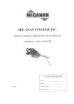
MICANAN SYSTEMS INC.
INSTALLATION AND INSTRUCTION MANUAL
MODEL: PRO-LT
2
\'EARWARRANTY
Feh 2009
wiring Diagram:
2
TABLE OF CONTENTS
PAGE:
VERIFICATION Of OPf,RATOR AND HAR}WAITII
3
SPFJCITICATIONS
4
SAFETY INSTRUCTIONS
5
TNSTAT,I,ATION
6
I,TMIT SWITCII ADJI]STMENT
t0
CONNI;CTION oF PowxR SIJPPI,YAND CONTROI, STATION
ll
CONNf,CTION OFREVERSING EDGtr DEYICE AND CON-TROL ACCESSORItrS _12
CT,I]TCI{ AD.IT]STMENT
13
BRAKE ADJT]STMENI'
13
EMERGENCY MANUAI OPERATION
t4
OPERATOR MAINTENANCE
15
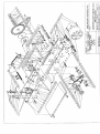
MECHANICAL DRAW]NGS AND PARTS LISTS
16
ELtrCTRICA]- DLA.GRAII{S
18
WARRANTY
19
FOR ANY QUESTIONS CONCERNINC THE SAFETY OR
OPERATION OF TTIIS OPERATOR PLEASE CONTACT
MCANAN SYSTEMS AT 1 877-888-1116
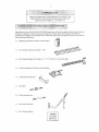
Upon delivery ofyour MICANAN SYSTEMS limited duty tolley door operator, please insp€ct the unil
caretully for danage. Ve'ify that operator horsepower, voltage, phase and amperage corespond to
the
available power supply and door application. Check that along with your operator you have
'eo€ivod
following standard hardware.
Ix
OPEN/CLOSE/STOP 3 button contlol station:
1x
Set of trolley tracks (door height +
Ix
Drive chain package (door height x 2 + 5' 6" (1.65n) c/w comectiDg
1
x
Ix
1
x
2'6")
Trolley ca.riage and 3/8 take-up bolt assembly
Trollev track md bracket
Frod idler
2 x Trolley
spreader
bds
Ix
Trolley arn assembly
Ix
Set of
waming Signs
lint)
PRO-LT medium duty trolley operator is designed for standard lift ovefiead sectional garage doors with
STANDARD OPERATOR WEIGET: 40-45 Lbs.
1000 RPM notor witl high stading torque.
Themaly proteoted by a built-in lhemostat that cuts power to the motor ard control citcujt
MOTOR: Idermitlent duty
-
when overheating.
- Horsepow€r:
1/2H?
- Voltage: I t5V, 220V l-phase
and puleys (l.5" ro 7" diameter)
Secondary: #41 chain and sprockets
REDUCTIONi Prjmary: (4L) V-belt
OUTPUT SHAFT SPEtrD: 90
RPM
DOOR SPEED: g"/second
SOLENOID BR4KE (OPTIONAI-): Solenoid Brake system available for model PRO LTB
WIRING TYPtr (STANDARD): C-2 Wiring conslant pressure on close, nonentary contact on
open and
stop. Wircd to accept revesing edge, radio control, pho.ocels, loops and OPEN/CLOSE devtces
NOTE: Ifnonentdn contact m close
ierminal #5.
TRANSIORMER: 24VAC control cicuit, supplies power to drive contlol relays \tith l5VA pover
available for extemal devices.
LIMIT ADJUSTMENT: 4 micm
switches that cootrol door 1travel. These limit switches are activated by
tully adjustable screw Dpe
cams.
EMERGENCY DISCONNECT: Quick release disconnecr door arm to allow person to disengage
operator drive chain *om door fo. manual ope.ation-
CLUTCH: Adjustable ftictiotr clutch
to
mininize
damage to door operator, door or vehicles.
OPERATOR DIMENSIONS:
DOBR HEIGHT PLUS
(I'lINIMUM)
Do
rct alov chndren
to play with door.
Before insiallaiion, be sule that operator is suited
Connect a rcversing device to
Place control device
cmor
preve
fff
qpe ofdoor and application
entrapment if door is located near pedestrian trafEc.
vithin clear sisht ofthe door but
at a minimum distance Fom the door so thal user
reach mo\ing door pdrb $heo ope'aung.
Outdoor extemal devices should have security features to Fevent Mauthorized opemtion ofthe door.
Nevercross under a moving door.
Press the "OPEN" device or activate quick lelease disconnect device
if a penon
is tiapped unde! the
Do not use fisconnect mechanism or manually opemte door unless power ha,s been electrically
Ke€p doors properly maintaioed. Test door and senioe regularly. Have a qualified service persotr make
rcpai's. An Lnnaintained doot srsten could cause injury or deatlL
The owner or users must udefttand the safery ard operation of door system. Insure that this
installation nanual be located close to tbe door system.
Note:
lnstallation of operator must be done by a qualified installer. Door must be prope'ly installed and
wo*ins smootlly. Remove all door locks prior to installation.
l.
lnstall control statior away fiom a[ moving doo. pans, widin sieht of rle door
5 ft (1.5 m) from fie eround.
2.
Insiall enhapment waming sign next to conllol statiotr.
6v
.r.,.at
"tl
3.
Do not rernove energency release tas attached to discormect handle
1-;;;)
l-l
t-l
al1d a
mi
nuro of
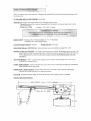
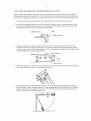
PREPARATION:
dd trolley tucks
on ground in fronl of door wiih door operaior motor facing
1
Lay ou! operator
2.
IJlstall tack spacen evenly io rrack asscmbly.
3.
L'lstall 3/8" iake-up bolt to cadage using lwo 3/8" hex nuts
ed
lock washer pmvided-
Slide trolley cariage rh.ough end of Lncks rowards operator wilh take-up bolt facing operator.
5.
Install front idler assembly to the second set ofholes €nd of tolley tracks.
6.
Boll rail assembly to operator fraire using four 3/8" x %" bolts and 3/8" seiraled hex nuts
provided.
FRONT IDI,ER
TRACK SPA(3R
CARRIAGE ASSEMBLY
OPBRATOR
Attach one end ofdrive chain to cariage usins connectjng lint pmvided. Run cllain around front
idler over the tack spacers, around dr;ve sprockel and comect to take-up-boh using connecting
link prcvided. Adjust take up boli so that chain sags approxinately 3" (7.5 cln) at midpoint of
tracks. Renove lidG from drivc chain ifnecessary to make proper adjustment.
FRONT IDIER
TAKE_UP BOLT
8
WAI,I, MOT]NTIN(l BIIACKf,T AND OPERATOR INSTALLATION
i
NOTE: Trolley tlpe operators sbould generally bc nounted diectly over the center oftbe door and lhe
lrolley tracks should clear the tracks by 2-112" (6.5 cm). However, if intedering structures or other reasons
do not allow for centered mounrjng, it is possiblc to install il up to I8" ofT-center for torsion spring doors.
Locate the cenler of door by measurjng door vidth
ad nark
a
vertical line above the door.
Deteimine rhe highest point ofdoor travel by neually openjng the door. Usiog a carpenter's lcvcl,
project a tine fiom where the top section of door reaches its hishest point. Mrk the spol here this
line (high arc) intersects witb the vertical line &awr earlier.
3.
Mount
a
vood block or angle iron to the wall abovc the door opening
as
shoim below The wall
has 3 holes lor anchor;rg to wood block or angle iron. Bncket should be centered
positioned so thar lhese holes are 2 I /2" (6.5 cn) above the high arc line of door. Secure
mountils bracket
vith door dd
vall mounting brackel using suilable hardware.
4.
Wlile allowing moro' to resl on floor.
wall mouniing brackets with 3/8"
5.
raise ftont end of lrack assembly and secure
bolts dd
(tut not righlen) to
nuts provided.
Swing the operator and track assembly above the level of the door tracks and t€mpor3rily secure m
place wilh rope or chain. Caretully open door. Align operalor and rails wilh center of door. Using the
door as suppon, shim the operator so that there is 3" (7.5cm) cleannce between door a boilom of
operator. Tighren wall mounting bracket bolts.
9
6.
lnslall hanging bnckets (blaces) frotn ceiling or structure 1o any of ihe 3/8" holes localed on
opemtor frame. For tacks over 14' lons it ;s reconncnded 1.) install braces to the tracks at 4'(1.2m) to
5' (1.5n) from operator.
BRACTS
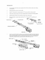
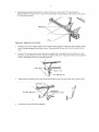
TROLLEY ARM INSTALLATION
1
.
2.
Manually close door to tuly closed position. Slide trolley cariage rowards front idler and latch trol]ey
arm 1o cariage spring pin by pulling on rope- W]rcn installed the open side of notch should facc the
Using
botis and nuls provided. align the nounting hol€s of strajght anl and cuned afin so rhal
the rop rollers oftbe door. Align door bracket with ccnterline
and secure to doorusing suitable hddware.
l/8"
pivotbolt on door bracket is i' linc virh
ofdoor
fI]P
3.
wlen property ifftalled
DOOR ROLLER
the door alm should lean slightly away fronl door wher door is
CARR1ACE PIN
SLIIING
4.
EIIERGENcY
SRACKE-I
At this time, check all bolts for lishhess
IISCONNECT ROPE
tully closed.
l0
LIMIT S\I'ITCH
Adjusrnent ofdoortravel is done by moving the limit cans on the threaded shaf| Theposition of
ihe 4 limit switches are faclory adjusled and should rot be altcred. Thc hnil switches are:
- "Open" Iimit srdtch: End of door travel in dt ftlly opcn position
- "Closed" linit sivitch: End oldoor tralel ;n thc tully closcd posilion
- "Advanccd Opcn" limit s$itch: Used for open/closc devices or timer 1() close features
- "Advanccd Closed" Limit switch: Used to prevent reversing device from re!€rsing
door when door is almost tul1y closed.
WARNING
TO REDUCE I'IIE RISK OF INJT]RY OR DEATH:
DO NOT ATIEMPT TO N,I-A]<E LIMII SWITCII DruSTMENTS
NI,F,SS POWFR HAS BEEN ELECTzuCALLY D]SCONNECTED
I
fq4diui! dss! !r!cl:
1.
Open cycl€:Depress can plale and spin "Open'limit cam away from "Opcn" limii swilch to
indease door tavel or spin "Open" limil carn rowards the "Open" limit switch to decrease
door lravel. After eacn adjuslnent ensure that cam plate tu]ly engases in slots ofboth limrr
2.
Adjusl
L
Clos€ cycl€i Depress cam plale and spin "Close" limit cam away lrom "Close" Iimit switch to
increase door travel or spln "Closc" limir cam towards rhe "Close" linit switch to decrease
door travel. Aftereach adjustnent cnsure that cam plare tully engages in slots ofboth ljmil
4.
"oper" limil can
Adjust"Closc"
linil
so that door slops at the desired
tu]ly open posilion.
cam so thal door stops ar the desired tully closed position.
ADVANCED OPEN LIMIT SWTCH
ADVANCED CIOSE LIMIT SWTCH
CLOSE LIMIT SWTCH
OPEN LIMITCAM
11
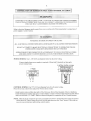
wi R SIPPI,Y AND CONTROL STATION
COMPARD AVAILABLE POWER SUPPT Y VOLTAGE TO OPI.]RA'IOR NAMEPLATE PR]OR
1O ELF]C'I'RICAL CONNECTION. FAlI-URI] TO CONNECT APPROPRIATE POWER SLTPLY
VOI TAGI] MAY CAUSE SEzuOUS DAMAGE TO OPER.{TOR.
Refer to electrical diagrams nrside conlrol box covcr or al &e end ofthis manxal
power supply or control stalion.
pior
10
conneciion
of
TO REDUCE THE RJSK OF INJURY OR DEATH:
ALL ELECTRJCAI- CONNECTIONS SHOUI,D BE NLADE BY A QUALIFIED SERVICE PERSON
DO NOT AT IE]\{PT TO MAI'E EI-ECTRICAI CONNECTIONS TO OPER{TOR UNLESS
POWER SI,TPLY HAS BEEN DISCONNECTED AT IUSE BOX
OPFRATOR I!4I IST BF CONNF,CTI-:D IN ACCORDANCE TO LOCAL ELECTR]CAI CODES
AND GROUNDED 'IO GRIEN GROIND J-UG LOCATED INSIDE CONTROL BIJX
POWER WIRINC: Usc 1-1/8" (2.85 cn) dianeter troles fbr all pouer $,iring.
Connecl singlc phase po$,er supllyro terninals L (line) andN (neutal) on t|ree-poie
powcr tcminal sf1p.
1-PHASE
3
BUTTON CONTROL STATION
@
2
CO\TROL WIRING: Use 7/8" (2.22 cn) diameterholes for all conlrol $'iring.
notru! control wires and power!'ires tu same corduil.
Note: Do
- lnslall conlrol staiion wilhin clear sighr ofdoor but asay from a1l moving parts ofdoor or hardware.
Install Entrapmenl wamrju sign nexl to control station. Connec! 3'button (ope close/siop) push butto'
stal;on to lcnnilals 2. 3.4 and 5. Reler to electrical diagran for comection of awo 3-button siarrons.
NOTE: After electrical conneclions are made. nanuallymove door to mid-position and, using the contml
station press Lhe "Open" button for s€vcral scconds and ihen prcss the 'Slo!" button. Ifdoor did not
movc irl corect direciion verify wiing conlrol sladon.
12
1-
R€versing Edge device (must be normally open contact):
If the door is controlled by any device or wircd in such a maoter that the door is not
controlled by constant pressure on close then an appropriate reversing edge must be installed
Note;
2.
External int€rlock Remove iumper betveen teminals
telmi.als.
1 and
2 and wne interlock behleen lhese two
Radio control rcceiver: Wire standard radio receiver to separate radio srrip on side of conrrol box or
10 ieminals 7, 8 and 9 on control teminal strip inside conlr'ol box-
r-
*--.]
ffrn
.-#-
l61616l
4-
Single button open-/close d evice: wire to telminals 7 and 8 on cotrtrol temrinal strip.
5.
Loop det€ctors, photocels and other revcrsing devices: Wte to terminals 3 and 6 on control
termitral strip.
@
4
o
6.
?4
Volt power: Wie to ieminals I
and 9 on control
leminal srrip
CONTROL TERIIINAL STRIP
@
tl
I.
2.
Remove cotler pin tapped to pulley.
Rotale clulch nul counterclocl:wise (loosen) until there is insufi'icient tension to pemit clutch to drivc
3.
Gradually tight€n clulch nul until ihe tension on belleville washen is sufficient to pemit clutch to
dr;ve door smoothly bul will allow clutch to slip if door is obsrructed. It should be possible to stop
moYing door by hand ifclulch is properly adjusled.
I ock clu ch nur in pldL e by n.ening co.1er pin
4.
USTMENT (FollSRO;gXE oniy)
The b'ake adjustnenl is factory se1 and should only require ninor adjustment after extensive use.
Veriry brake adjusLnenl by manually holdiog in solenoid pluDger. wlien blake is properly adjusted, the
brake shoe pads should make complete contact with brake drum with sufficienl brake spring tension to srop
and maiDlain door when solenoid is de-enersized. wlen solenoid is energized, brake shoes should release
from drum with sumcient clearance to avoid contact between shoes and drum.
- To adjusl brake teffion, tighten (io increase) or loosen (to decrease) nylon lock nur on blake spring bolt.
Obsene solenojd during electical lesling ofbrake. Blake spring lension mustbe adjusled so that solenoid
should pull and rel-aso smoolhly and quiedy. Too much or too litlle tension on brake spring may cause
solenoid to bum out.
- To adjusi individual brake shoes, loosen nur on brake shoe adjustnent bolt and adjust bolr. Wtren prope y
adjusted, dlere should be a small cleannce bef'een adjustnenl boh and solenoid bracker when solenoid is
de-energted. wlen solenoid is enersized, brake shoes should move away liom drum with sufficienr
clearance 10 avoid friction b€tween brake shoe pad and dnm. After adjuslDrents are made be sule to tighten
nuts on brake shoe adjustment bolts.
SOLENOID
SOLENOID LEVER
BRA(E SHOE
ADJUSTT4ENT BOLT
BRAI(E SHOE
ADJUSTMENT Nt]
BRAKE SPR
BOLT
BRAKE SHOE
BRAKE SPRING
BRAKE PAD
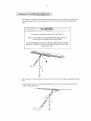
14
-
The operator is equipped
l.
Pu[ fie release cord dowrwards to disconnect trolley am fiom cariage aod manual]y operate
2.
To rccornect door arm to carriage, pull energency release cord and re-insert troley am to
lxolley carriage sping pin.
wit! a quick release discormect system to manually opmte door in
case ofemergency. This feature should not be used to maiually operate a naltunctionins
15
TO REDUCE THE RISK OF INruRY OR DEATH:
DO NOT ATTEMPT TO SERVICE THE OPERATOR IJNLESS
POWER SUPPLY }IAS BEEN DISCONNECTED
Inspect manual tunction ofthe door every 3-lnontls. MalG sure that door runs snoothly. If
door does not manually open or close freely, have a quaiified ser.r'ice penon mate repairs- Do
not atkmpt 10 electrically operate a malturctioning door.
Everv 3 months:
L Vedry that door area is kept cled. Remove any obshucrions that would prev€nt proper
door operation.
2. Check for any excessive slaok in chains. If chain adjushnent is required v€rify and
adjust linit switches, if neoessary.
3. Ve.ify ard adjust clutch and brake (Do not lubdcaie).
4. Lubricare chajnr, beuings d luDrr shaIL.
5. Veri& that motor aad opentor mns smoothly and quiedy. Veriry dlat
carriage runs snoothly on tracks.
Everv 6 months:
1 . Verifo tiehtness of all fasteners and set screws.
2. Veriry thai ope.ator is properly secured.
3. Inspect maual discormect.
4. Verify tension and condition ofv-belt
Everv 12 months:
L Pe'fom a complete se.r'ice oheck.
2. Veriry $at irside ofcontrol box is clean and thar gmunding \rjres, terminations and
|o$e' reminzrionr do nor .bow srgo. of conosior
3. Veriry tightness of all leminal stdp screws and eleclrical connectioDs.
4. Veriry power supply, voltage of input leminals during operation5. Veriry that curent consumptjon of operator coresponds to nameplate infomralion
z
o
F
F!
i!tr
O
d
LI] 6
F
>H n
FFI
PA
).
z
z
F]
Fr
d
t:
z
n
:
n
F.]
-2
2n
:J
.=H=t
:sE9;j
a
&
1"14I
-z
<E
a\
7i\
\!/
sa--%
--
-/Ar
\!l/
{
z
o
a
&
t1
Replacement parts list PRO-LT/LTB
FRAMF I FF-')MSroosT
FRAME IR GHTI MS OO93
-N-RoaEox (Lrmiied D,'v) MSroo92
'.NrRor Bol.o\ER lLiinrted dury) rrls 00q
''lto
t
i
SHAFr3r&t2xea36
.AM 1/220!NF
1ROME T BLSHING3]3' D
XMT SWTCH
RI:FHtrLrps
Fx prrtrlFs
5
rlr,lcHrfuE scREw 4_40
MACFTjNE scREW 6 32
uNcxir/2
uNc,1"
2
' 3D o'
"oMPRESs,o\ ""\Gr
]_r
a6NTRoL Box,qr.rcE
frmoR PUaIEY aL
ffi
L)
D
KFYWAY3/16SO'I1/4LONG
PILLE! 7 OD dwBUSN NG
. r.l
aFRtrrG
tq
D
PLATE ALUMTNUT,T 3r.1 ro
Pr,fit.x2lLoNc
BE_ILEVILLELLEVILLEWASIiERI3/16DI1.3/1611/3
lonER PrN 1/3r2.5 LONG
tsE NtLoN LocKNUr ,uNc
-6r ! AR
r
r]rr
ANGE BEARNC374' DX1'3/3OD
LANEftEARTIG
r'D
x 3/3"
tl6i6LaER-HAii7
?oD
prrcH
c^! coNNEcr
R BEFD HEX NUT 3 32UNF
tl
R.irfRaNAf\37 PncH
-RocKEraroBs
<EYWAY r/4 SO x 1 1/4
aFfuFN
oRtrrE
Nc
L
N\
c^rvl oFFsErLINK
+
I coNN
L NK
LG
3r16"x1"tc'LoNG
L-MfiEDDUTYFRAMESUPPoRTI]'BR4q!!EII4!]!.]J]
H-oirFD SELF RouNohicWAstsER HEAD scRFWr0 32 UNF x ll2'
i ts Ro r 3/s' 16uNc x 3/.1 LONC
5'l
3i-iFNarD LEVER LrMrrlED DUTY Msl00s4
i ts pH[ Lrps MACHTNE scREW 10.32 uNFxs/3"
HEXNYLON NU'
1(r 32 UNF
funsrEEL
EUSHTNG 9/32rD x 13/320D x1-1116
-,RAKE COMPRESSTON SPRING(5/16"O'.05G 2 501)
HE7 NYLON LOCA NIJI II+zOUNC
HFxHFAD BoLT 1r4 20UNCx r-1/4'{Fu Iri€ad)
llir€ad)
tsEX HEAD BOLT
20UNC x 4" (panid lhread)
NEX HEAD BOLT t4
'+20UNCx2'(ful
SPRNGPN lri6"
\
1 l/4_Lonq
R BBED HEXNL]T 1O 321]NF
FTATWASHERl3/16' D.xl soD(3/4"sHAFrszE)
NPUI SHAFI PRO LI3/4 x l0a7s"
DRIVE SHAFTTROLLEY ]' X 3 75'
Hl.r. aLorr=b sErF RouNDr\c wAsr-rER
HEX NLrr 1/a '20 uNc
RIRBFD HEXNUT3]3' 16UNC
-FFnE Pr,\316iT 1 1,2 LoNG
sNAFl3/c
FRAMaSIF-oRr
-TBBED
x6" LoNG
!!4Q 9!EE!!j!!!
!!l
s
L
INTERCIIANGE RED
a9
L?3456
A
/\
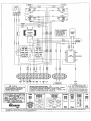
wmlrrc
MICANAN STRONGLY RECOI'MENDS THE
IJSE OF ENTRAPMENT PROTECTION
(
SYSTEhS WHE S2
OMENTAIY
CON'ACT) wlRING S USED.
i
ING
LEI''VES THE FACTORY WTH A'C2" WIRINC 'IHAT CONSTANT PRESSURE IS REOUIRED
CLOSE THE DOOR.
- IS DESIRED, TNEN
IF
OFERATION ON CLOSE -'32'WRING
'O
IHIS OFERAIOR
'IO}IENTARY
REINSTALL
T}IE PITPLE WRE
ON TO
TERMIML
'5.
/\
1!l
IF STOP 8UTTON NOT I]SED.
aDD JUT,TFER BETTVEEN 2 & 5,
NOTE, t4lNlHUr 13 AwG WRE MUST
SE USED FOR FIELD CONNECTIONS.
T/G.I I/zHP IIO\
MSLT/G.'-WW
-PHASF PFd-I
REV
F I IIATF' 29 OI 07
CANADA: l-(877) 888-lll6
--.
MICANAN
rHE
NFOR!4I!!!!f4!Eq!EREI
IS MOPRIETARY:TO
'lCN
SYSTE
iS
NC dO SB^LL NOT gE
BETRODUCED OR d
SC
LOSED
q!
lqEq
IqLIIY
DES]ILqR MUFACruRE
EXCE
PT WHEII
6dR
MICANAN SYSTEMS waranls that malerials and workmanship are free from defects for a period of
ftvo ycars from th€ dale ofinvoice. Materials rciumed to Micdan dccned dcfeclive afler eramination
will be rctumed at the oplion ofMicanan sith rcpaned, nev or rc ndufaotured pads.
MICANAN
will not be responsible for my exta charges incurred in thc proccss of relurning
All retumed material musl be reccivedpre paid or il will not bc acccptcd
SYS I EMS
defective material.
This wararty is limned, and in ]ieu ofall other wananq' expressed or implied. There is no expressed
liability due on the pan oftne seller.
MTGA]IA]I
Commer.ial Door Opening Devices
MICANAN SYSTEMS INC.
HEAD OFFICE
1380 St-Regis
Dorval, Qu€b€c
Canada, H9P 2Ts
PHOENLX
1236 W. Southcrn Av€.
Suite 104
Tempe, Az
usA
Tf,L: (s14)
822-1116
1-877-888"1116
FAX: (sl4) 822-1r18
85282
ATLA.NTA
2885 N. Berkeley Lak€ Rd.
Suite 7
Duluth, Ga
ItsA 30096
CHICAGO
706 R€ningtotr Rd.
Srife D
Schntrmburg,
fisA
Il
60173
TtrL: (480) s57-0070
TEL: (678) 584-2543
TtrL.: (847) 839-8303
l-888-816-8584
FAX: (480) 5s7-8188
1-800-798-25,t3
l-800-670-8303
FA-X: (847) 839-8308
l'AX: (678) s84-2s44