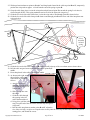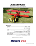
1
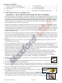
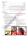
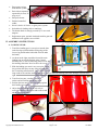
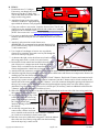
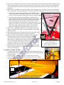
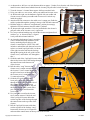
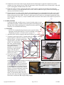
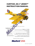
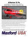
Albatros D.Va
1/5 SPORT-SCALE ARF R/C MODEL AIRPLANE
INSTRUCTION MANUAL
Shown with optional machine guns, Uranus 638109 motor and 18x8 wood propeller
The Albatros D.III was a single-seat biplane used by the Imperial German Army Air Service and the Austro-Hungarian
Air Service during the First World War. It was heavily armed with twin synchronized, forward-firing 7.92 mm LMG
08/15 machine guns and powered by a 180 hp Mercedes 6-cylinder inline, water-cooled engine (unusual for the time), and
its streamlined radiator, mounted on the top wing, was offset slightly to starboard so that combat damage would not result
in scalding water being released over the pilot. The prototype first flew in August 1916 and was quickly recognized for its
outstanding maneuverability and rate of climb. Like most fighters, the Albatros was prone to spinning. However, its
recovery was straightforward, and German aces including Manfred von Richthofen, Ernst Udet, Erich Löwenhardt,
Kurt Wolff, and Karl Emil Schäfer credited the D.III as being both pleasant and easy to fly.
The Albatros D.Va was the final development of the Albatros D.I family, and the last Albatros fighter to see
operational service. The D.V entered service in May 1917 and, like the D.III before it, immediately began experiencing
structural failures of the lower wing. Indeed, anecdotal evidence suggests that the D.V was even more prone to wing
failures than the D.III. Albatros responded with the D.Va, which featured stronger wing spars, heavier wing ribs, and a
reinforced fuselage.
The Maxford USA 40-inch Albatros D.III was the 1st RC Albatros available in the RC world. This 1/5 sport scale
Albatros D.Va is our 2nd ARF RC Albatros.
We invite you to enjoy the pride of ownership and the joy of flying this
beautiful ARF sport-scale model of the famous Albatros D.Va fighter.
Copyright 2014 Maxford USA
Page 1 of 18
#S140620
TABLE OF CONTENTS
I.
II.
III.
IV.
Safety precautions & assembly tips ....................
Warranty, liability waiver & return policy ..........
Specifications ......................................................
Parts list ...............................................................
2
3
4
4
V.
VI.
VII.
VIII.
Special features .................................................... 4
Assembly Instructions ......................................... 5
Setup and adjustments ........................................ 17
Storage, field setup & preflight checks .............. 18
I. SAFETY PRECAUTIONS & ASSEMBLY TIPS
(IMPORTANT – READ THIS SECTION BEFORE YOU BEGIN ASSEMBLY)
1. This product should not be considered a toy, but rather a sophisticated, working model that functions much like a fullscale airplane. Because of its performance capabilities, this product, if not assembled and operated correctly, could
cause injury to you or spectators and damage to property. Maxford USA provides you with a high-quality, thoroughly
tested model airplane kit with assembly instructions. However, the quality and capabilities of your finished model
airplane depend on how you assemble it, and your safety depends on how you use and fly it. Any testing or flying of
this model airplane is done entirely at your own risk.
2. Assemble this model airplane according to these instructions. Do not alter or modify the model beyond the assembly
and power-system options covered in these instructions, as doing so may result in an unsafe or unworkable model. If
the instructions differ from the photos, the written instructions should be considered correct. If you have any question
or concern about these instructions, before you proceed with assembly of this product, contact your dealer or speak to a
Maxford USA customer service representative at 562-529-3988 (Monday through Friday, except national holidays,
9 AM to 5 PM Pacific Time).
3. While this kit has been flight-tested to meet or exceed our rigid performance and reliability standards in normal use, if
you elect to perform any extremely high-stress flying, such as racing or advanced aerobatics, or if you install a much
larger power system than specified, you (the buyer or user of this product) are solely responsible for taking any and all
necessary steps to reinforce the high-stress points and/or substitute hardware that is more suitable for such increased
stresses.
4. Throughout the lifetime of this model, use only the Maxford USA-recommended power system and a new or wellmaintained radio-control system.
5. It is your responsibility to install the receiver and connect the R/C components in such a way that this model airplane
passes all applicable safety/range tests and that the power system and controls operate correctly and smoothly.
6. Recheck the operation of this model airplane before every flight to ensure that all equipment is still operating correctly
and that the model has remained structurally sound. Also before every flight, check all electrical, control and structural
connections; do not fly without replacing any that you find damaged or worn.
7. Before you begin assembly of this model airplane, read all instructions and test-fit each part to ensure you fully
understand the instructions and that no parts are missing, damaged or unsatisfactory. Temperature and/or humidity
differences between the factory, our warehouse and your home or workshop may dictate the need for slight
adjustments to the wings, struts and/or the vertical or horizontal stabilizer’s mounting surfaces to ensure proper
alignment; however, we recommend you contact us before you attempt any such adjustments.
8. To help ensure the security of your servo connections, we recommend use of optional Maxford USA
servo-extension safety clips.
9. If you are not an experienced R/C pilot or have not flown this type of model before, we strongly urge
you to get assistance from an experienced R/C pilot.
10. You may use 30-minute epoxy to attach critical parts permanently (such as where the horizontal and vertical stabilizers
attach at the end of the fuselage) and apply a threadlock compound to secure all airframe components from vibration.
11. If you have concern about the security of any factory fabrication procedure(s), you may apply 30-minute epoxy around
the perimeter of such part(s) as an extra safety precaution.
12. After adjusting each clevis, secure the clevis to its threaded rod with CA adhesive.
For additional safety, hold the clevis closed by
adding a small piece of tubing (not supplied) as shown at the right.
13. For your safety, do NOT leave any strands of wire poking out from the end of any crimp
tube. Exposed small steel strands can be sharp enough to cut or abrade skin!
Copyright 2014 Maxford USA
Page 2 of 18
#S140620
14. This model may include some plastic, fiberglass and/or carbon-fiber-reinforced parts. If you drill, grind or sand any
such part, always wear safety goggles, a particle mask and rubber gloves to guard yourself from eye, skin and
respiratory-tract irritation; never blow into the part as the dust may blow back into your face.
15. Minor production details (such as Mylar or paint colors) may vary. Check the Mylar covering material’s joints and
surfaces; if necessary, carefully use an iron (do NOT set the iron’s temperature too high) to secure the edges and to
tighten any loosened areas. Recheck and retighten from time to time.
16. If you use an electric power system, read all instructions included with your battery and charger. Failure to follow all
instructions could result in permanent damage to the battery, its surroundings, and bodily harm! If you crash this model
airplane, check whether the battery is damaged. Do NOT attempt to use or recharge a damaged battery.
II. WARRANTY, LIABILITY WAIVER & RETURN POLICY
Maxford USA guarantees this kit to be free from defects in material and workmanship at the time of purchase. All our
products have been inspected in our factory and are checked again when shipped from our warehouse. However,
Maxford USA cannot directly control the materials you may use or your final assembly process. Therefore, Maxford
USA cannot in any way guarantee the performance of your finished model airplane. Furthermore, in purchasing this
product, you (the buyer or user of this product) exempt, waive, and relieve Maxford USA from all current or future
liability for any personal injury, property damage, or wrongful death, and if you (the buyer or user of this product) are
involved in any claim or suit, you will not sue Maxford USA or any of its representatives.
If you do not fully accept the above liability and waiver, you may request a return-merchandise authorization number
(RMA#) as explained below in item 2. If you think there is a missing, damaged or unsatisfactory part, please read our
after-sales service and return policy:
1. Inspect your order upon delivery for any missing, damaged or unsatisfactory part(s). If you believe there is a
problem, you must call us at 562-529-3988 (Monday through Friday except holidays, between the hours of 9 AM
and 5 PM Pacific time) before you begin assembly and within 10 days from receipt of your purchase. During this
telephone conversation, and with your support, we will determine how to resolve your concern.
2. To request a return-merchandise authorization number (RMA#), call 562-529-3988 (Monday through Friday except
holidays, between the hours of 9 AM to 5 PM Pacific Time). If we elect to issue you an RMA#, you must clearly
mark this RMA# on the outside of the package. (No return or exchange will be authorized after 10 days from the
date of your receipt of the product; any package delivered to us without a Maxford USA RMA# is subject to being
returned to the sender, as received, with return postage payable upon delivery.) Returned merchandise must be in its
original condition as received from Maxford USA, with no assembly or modification, in the product’s original
packing materials, complete with all manuals and accessories. Return shipping and insurance charges must be
prepaid by you, the buyer.
3. Returned merchandise that is accepted by Maxford USA for credit is subject to a 10% to 20% restocking fee (the
final amount will be determined by Maxford USA upon receipt and examination of the returned merchandise).
Return address:
Maxford USA
15939 Illinois Avenue, #B-C
*
Paramount, CA 90723
IMPORTANT: Print the RMA# issued by Maxford USA
on your package near our address.
Copyright 2014 Maxford USA
Page 3 of 18
#S140620
III. SPECIFICATIONS*
Wingspan ................................................................................................................................................. 70 inches
Wing Area ............................................................................................................................................. 1,241 sq in
Length ...................................................................................................................................................... 57 inches
ARF weight ............................................................................................................................................... 9 pounds
Flying weight ................................................................................................................................. 14 to 15 pounds
Power system ...................................... 0.90 to 1.20 2-stroke glow engine or Maxford USA U638109 motor with
100A HV ESC and 10S to 12S 3,000mAh or greater LiPo battery or equivalent
Propeller ............................ Glow 16x8/10; EP 18x8 or 19x6; or as recommended by the power system’s maker
Radio ................................................................................................................................. Minimum of 4 channels
Servos ................................... 2 standard-sized servos (rudder & elevator) and 2 mini- or micro-servos (ailerons)
plus an additional standard-sized, mini- or micro-servo for throttle if a glow engine is used
Center of gravity (CG) ......................................................... 4 to 4 1/4-inches behind the top wing’s leading edge
*(All dimensions and weights are approximate.)
IV. PARTS LIST
A. SUPPLIED ITEMS:
• Prebuilt and Mylar-covered fuselage, upper and lower wing panels, top wing’s center section and ailerons,
horizontal stabilizer, elevator, vertical stabilizer, rudder, and fin (with articulated, spring-loaded tail skid).
• Dummy engine.
• Prepainted 5 1/2-inch diameter spinner.
• Dummy radiator with hoses.
• Landing gear and interplane struts.
• Nose hatch secured by rare-earth magnets.
• Hardware package.
B. ITEMS YOU MUST SUPPLY TO COMPLETE THIS ARF:
• Epoxy and cyanoacrylate (CA) adhesives and threadlock compound.
• Low-tack masking tape and common tools (screwdriver, pliers, etc.).
• A 4- (or more) channel radio system; three 6-inch servo extensions, one 12-inch Y harness and two miniservos for ailerons; and two standard-sized servos for rudder and elevator.
• 18- or 19-inch diameter x 8- or 10-inch pitch propeller, or as specified for your engine or motor.
• Glow engine power system:
• Electric power system:
▫ 0.90 to 1.20 cubic inch 2-cycle engine
▫ Maxford USA U638109 outer rotor motor
▫ Compatible fuel tank and fuel tubing
▫ Maxford USA 100A HV ESC
▫ One additional mini-servo plus one 10-inch servo
▫ 10S to 12S LiPo 3,000mAh or greater battery
extension for throttle control
(or equivalent 1,200-Watt or greater outer rotor
motor with compatible electronic speed control
and battery)
C. OPTIONAL DETAIL-UPGRADE ITEMS YOU MAY CHOOSE TO ADD:
• Simulated pilot and machine guns.
V. SPECIAL FEATURES
•
•
True-to-scale large-sized spinner,
radiator, dummy engine, windshield
and optional guns.
Shock-absorbing tail skid.
Copyright 2014 Maxford USA
Page 4 of 18
#S140620
•
•
•
•
•
•
•
•
Easy-remove wings
with Maxlok system.
Each aileron separately
operated by its own, inwing servo.
Pull-pull elevator.
Pushrod-controlled
rudder.
Owner’s choice of electric- or glow-power system.
Included scale-looking stick-on markings.
The bottom hatch is strongly secured by 12 rare-earth
magnets.
Replacement parts, optional simulated-machine guns and
additional scale upgrades are available.
VI. ASSEMBLY INSTRUCTIONS
A. LANDING GEAR:
1. Test-fit the landing gear’s cross-pieces into the slots
in the fuselage (one behind the trailing edge of the
lower wing and the other behind the firewall under
the hatch).
2. As shown at the right, attach the front of the main
landing-gear strut to the fuselage using 2 metal
brackets, four 3/4-inch (15mm) long wood screws and
the markings that show where to drive the screws.
3. Slide the landing-gear strut’s rear cross-piece into its
slot, position the spacer on top of the strut, and use
the 2 remaining metal brackets, four 3/4-inch (15mm)
long wood screws and the markings that show where to attach the landing gear to the fuselage as shown at the
right.
4. Test-fit an inner nut, a washer, a wheel, 2nd
washer and self-locking nut on each axle.
5. Position the inner nuts so they rest firmly against
their landing-gear struts.
6. Adjust the self-locking nuts on each axle to
secure the wheels to their axles and to allow each
wheel to rotate smoothly.
Copyright 2014 Maxford USA
Page 5 of 18
#S140620
7. As shown at the right, align each
hubcap’s round post to the round
opening in the hub of each wheel.
Press the retaining clip at the end
of the two remaining posts into
their rectangular openings in the
hubs.
NOTE: Wheel color may vary.
B. TAIL SECTION:
1. Slide the lower wing’s carbon-fiber rod midway through its opening in the fuselage.
2. Test-fit both halves of the horizontal stabilizer (with the white sides toward the bottom of
the fuselage) into the slots in the sides of the fuselage. Align the horizontal stabilizer so it
appears parallel to the carbon-fiber rod.
3. If necessary, cut through any excess Mylar covering the CA hinge slots and use 4 CA hinges
to temporarily fit the elevator to the horizontal stabilizer. Align the black and white trim on
the elevator and horizontal stabilizer. Remove the elevator from the horizontal stabilizer.
4. Ensure good wood-to-wood glue joints by removing any excess Mylar from where each half
of the horizontal stabilizer slides into its slot.
5. Use epoxy to secure both halves of the horizontal stabilizer into the slots.
6. Before the epoxy fully cures, use 4 CA hinges and CA adhesive to permanently attach the
elevator to the horizontal stabilizer and make any final adjustment to the position of the
horizontal stabilizer.
7. Test-fit the upper vertical fin into its slot at the top of the fuselage. Align the upper vertical
fin at 90 degrees to the horizontal stabilizer.
8. Ensure a good wood-to-wood glue joint by removing any excess Mylar that enters the slot.
Secure the upper vertical fin in its slot with epoxy.
9. If necessary, cut through any excess Mylar covering the CA hinge slots and use 2 CA hinges
and CA adhesive to permanently attach the rudder to the upper vertical fin.
10. Test-fit the lower vertical fin (with preattached tail-skid assembly) into its slot in the bottom
of the fuselage. Align the lower fin at 90 degrees to the horizontal stabilizer.
11. Ensure a good wood-to-wood glue joint by removing any excess Mylar from the lower
fin that enters its slot.
12. Secure the lower fin in its slot with epoxy.
C. TOP WING’S CENTER SECTION & NOSE:
1. Slide 2 carbon-fiber rods midway through their
Typical
openings in the top wing’s
guide-hole
center section.
2. Use the guide holes to attach the lower radiator
assembly to the bottom of the top wing’s center
section with four 3/8-inch (10mm) screws.
Copyright 2014 Maxford USA
Page 6 of 18
#S140620
3. Use epoxy to attach the simulated radiator lever into its opening in the bottom of the top wing’s center section
behind the radiator.
Front cabane
4. Use 9/16-inch (15mm) long
struts are
wood screws to install one
longer than
wing-wire anchor and one
rear cabane
cabane strut at each of the
struts.
openings in the bottom of
the top wing’s center
section as shown.
5. Secure a
carbonfiber
diagonal
brace
between
Lower radiator assembly
Nose
each set
of cabane
struts with 1/2-inch bolts and self-locking nuts
as shown above.
6. Cut mounting slots and use epoxy to secure the
Windshield pictured
windshield on the decking in front of the cockpit.
on 1/4-inch squares
7. Temporarily position the dummy engine in its opening (do not apply glue at this time).
(NOTE: This is a good time for a ‘creative’ modeler
to consider the option of using the rectangular opening near the front corner of the lower
radiator for the radio system’s on/off switch. The supplied 8-inch wire pushrod may be reshaped and used for
switch control, and the switch’s wiring may be routed into the fuselage with the aileron-servo wiring.)
8. Test-fit the optional guns on either side of the dummy engine, but do not apply glue at this time.
(NOTE: As shown below, a set of optional guns also includes a set mounts.)
9. Position the top wing’s center section
above the fuselage with the lower ends
of the cabane struts over their openings
in the fuselage. Align the carbon-fiber
Nose
rods in the top wing’s center with the
lower wing’s carbon fiber rod and with
the horizontal stabilizer. (NOTE: If
desired, at this time the angle of attack
of the top wing may be ‘fine-tuned’ to 0
degrees relative to the horizontal
Diagonal braces, wing wire anchors,
stabilizer by adjusting the position of
windshield, dummy engine and machine guns
the cabane struts on the sides of the
are not shown in this photo.
fuselage.)
10. Attach the cabane struts to the fuselage with 9/16-inch (15mm) long wood screws as shown above.
11. Carefully remove and safely set aside the dummy engine and machine guns to avoid damage during the
following assembly steps.
Copyright 2014 Maxford USA
Page 7 of 18
#S140620
D. WINGS:
1 5/8 inch
1. Each aileron uses 3 CA hinges.
If necessary, cut through any excess
Mylar covering the CA hinge slots.
8½ inch
15¼ inch
Test-fit and center the ailerons and CA
hinges to their wing panels.
2. Attach the ailerons to the wing panels
with thin CA adhesive. Apply masking
tape to hold the ailerons evenly aligned with their wing panels.
3. Using your radio or a servo tester, center the aileron servos. Test-fit your
aileron servos, the supplied aileron pushrods and wooden servo mounting
pedestals to the servo-hatch covers.
(NOTE: Servo tester info. is at http://www.maxfordusa.com/servo.aspx.)
Mini-servo
4. Use epoxy to attach the pedestals to the servo hatch covers. Use the
hardware provided with your servos to mount the aileron servos on their
pedestals.
5. Attach a 6-inch extension to each aileron servo.
Bottom side of left
(REMINDER: We recommend using optional Maxford USA
wing panel is
servo-extension safety clips to secure all servo extension and
Y-cable connections.)
pictured
Clevis
6. Use a length of coat-hanger or heavier wire to guide the
aileron-servo extensions from each servo bay out through the
root rib of each top wing panel.
7. As shown at the right, secure the aileron servo hatch covers to
their wing panels with 5/16-inch (1cm) wood screws.
8. Position the aileron control horn assemblies directly behind
your aileron-servo’s output arms at the front edge of each
aileron. Drill 5/32-inch holes for the control horns in the
EZ-link connector
ailerons and mount the control horn as pictured at the right.
9. Attach an EZ-link connector to each horn. Twist each horn approx. halfway onto its threaded rod as shown above.
10. Attach the supplied aileron pushrods between the aileron control horns and aileron servo output arms. Remove the
masking tape from the ailerons and wing panels.
11. Attach a 6-inch extension to 1 of the 2 ‘arms’ of a 12-inch Y-harness. Position the Y-harness and extension inside
the top wing’s center section. Position the identical connectors from the Y-harness and its 6-inch extension at the
outside ends of the center section. Guide the Y-harness’ servo-like connector through the opening in the bottom of
the top wing’s center section and down into the fuselage through the opening at the rear of the dummy engine.
Attach the servo-like connector to your receiver’s aileron port. (If necessary, attach an additional extension to the
Y-harness’ servo-like connector to reach the reciever.)
12. Slide all 4 wing panels onto their wing rods. Guide each Maxlok tab at the root ribs of the lower wing panels into
their matching slots in the fuselage.
Top
13. As pictured at the top of page 5 and
w
i
n
g
at the right, secure the lower wing
Top
panel
panels to the fuselage by inserting
wing’s
Maxlok
the 2 longer Maxlok pins
c
enter
tab
into their openings in the bottom of
section
the fuselage.
14. As each top wing panel nears the
Shown on 1/4-inch squares
center section, connect an aileronservo extension to the end of the center section’s Y-harness
(or 6-inch servo extension) as shown at the right.
15. Push the excess wires inside their wing panels. Guide the Maxlok
tabs at the root ribs of the top wing panels into their matching
slots in the top wing’s center section.
Copyright 2014 Maxford USA
Page 8 of 18
#S140620
16. Secure the top wing panels to their center section by inserting the 2 shorter Maxlok pins into their openings in the
bottom of the top wing’s center section as pictured at the top of page 5. (NOTE: A conservative customer who is
not concerned about disassembly for transport or storage may permanently secure the wings to their wing rods
with epoxy.)
17. If necessary, cut the Mylar covering the ‘pockets’ for the interplane struts: 1 in the top of each lower wing panel
and 2 in the bottom of each top wing panel. Test-fit the carbon-fiber interplane struts into their pockets as follows:
a. Carefully spread the wings apart and insert one end of the longer
struts into the pockets in the bottom wing panels. Fit the other ends
into the pockets nearest the leading edges of the top wing panels.
b. Locate the ends of the shorter struts that have 2 holes and insert
them up into the pockets nearest the trailing edges of the top wing
panels. Align the holes at the free end of the short struts with the
holes in the longer struts nearest the lower wing panel. Test-fit 5/8inch (15mm) long bolts into these holes as shown at the right.
(NOTE: At this time you may check or adjust that the angle of
attack of the wings remains 0 degrees relative to the horizontal
stabilizer by adjusting the depth of the struts in their pockets.)
18. When you are comfortable with the fit of the interplane struts, apply
epoxy to both ends of the longer struts and permanently secure them
into their pockets.
19. Apply epoxy to the ends of the shorter carbon-fiber struts that have 2
holes. Insert them into their pockets in the top wing panels.
20. Install 5/8-inch (15mm) long bolts and matching self-locking nuts
in the holes at the free/lower ends of the short struts and in the
Nose
lower end of the long struts. If you plan to install wing wires,
install wing-wire anchors on these bolts as shown at the right and add
Position the wing-wire anchors
5/8-inch (15mm) bolts and wing-wire anchors to the holes in the tops
toward the fuselage
of the struts. (NOTE: Now, before the epoxy has fully cured, is your
on
the
5/8-inch (15mm) bolts
last chance to ‘fine-tune’ the wing’s angle of attack.)
(NOTE:
Hardware may vary.)
21. Apply masking tape between the top and bottom wing panels to hold
them in position until the epoxy cures. When the epoxy is cured fully,
remove the masking tape.
Shown: Left side of vertical
s
t
abilizer, rudder and fuselage
E. RADIO-CONTROL SYSTEM:
1. As shown at the right, secure the rudder’s control-horn attachment bolt in its
predrilled hole at the base of the rudder – with the bolt projecting from the left
side of the rudder.
2. Twist the rudder’s control horn approx. 3/4 of the way onto its bolt.
3. Twist a clevis onto the rudder’s pushrod. Attach the clevis to the rudder’s
control horn as shown at the right.
Clevis and threaded rod
Wire loop and crimp tube
2-inches
(5cm)
Shown: Right side of vertical stabilizer, rudder,
fuselage, horizontal stabilizer and elevator
Copyright 2014 Maxford USA
Page 9 of 18
#S140620
4. As shown above, drill two 5/32-inch diameter holes at approx. 2 inches (5cm) from the end of the fuselage and
install elevator control horns behind where the elevator pull-pull cables exit the fuselage.
5. Twist the elevator’s 4 control horns approx. halfway onto their bolts.
Rudder’s
6. Using your radio or a servo tester, center your rudder and elevator servos. pushrod
7. As shown at the right, use the hardware supplied with your rudder and
elevator servos to mount your rudder and elevator servos in their tray
inside the cockpit.
8. Attach an EZ-link connector to the rudder servo’s output arm. Guide the
rudder’s pushrod through the opening in the top of the EZ-link connector.
9. Hold the rudder in a centered (‘straight ahead’) position, then snugly
tighten the EZ-link connector onto the rudder’s pushrod.
Standard10. As shown at the right, attach the 2 clevises preattached to the elevator’s
sized
pull-pull cables to the elevator servo’s output arm.
servos
11. Use scrap wood and masking tape to hold the elevator straight and level
(with no ‘up-’ or ‘down-elevator’), aligned
evenly with the horizontal stabilizer.
12. As pictured at the bottom of page 9, attach the
4 clevis-and-threaded-rod assemblies (with
loosely attached pull-pull cables) to the
elevator’s control horns. (NOTE: This ARF
includes a carbon-fiber tube that can be used to
replace or reinstall a pull-pull cable. As shown
at the right, insert the tube into the fuselage
through the opening in the tail, guide it to the
elevator servo, and feed the wire through the
tube.)
13. Guide the ends of the 2 pull-pull elevator cables
that exit the lower sides of the fuselage through
the control horns on the bottom-side
of the elevator.
Openings for pull-pull cables in the right side of the fuselage
14. Pull the cables “snug” between the
elevator servo’s output arm and each of
the elevator’s 2 lower control horns. (Do
not pull so hard as to accidentally move
the elevator servo’s control arm from
it’s centered position.)
15. Guide the free end of each of the 2
lower pull-pull elevator cables back
through its crimp tube, adjust the size of
the resultant loop, and use pliers to
crimp each tube onto its cable. Snip off
the excess elevator cable’s ends with a
pair of cutting pliers and discard the
excess cable.
16. Use your radio to confirm the elevator
servo remains centered. Guide the end
of the 2 pull-pull elevator cables that
exit the top-sides of the fuselage through
the control horns on the top-sides of the
elevator.
17. Pull the 2 pull-pull elevator cables that
exit the top sides of the fuselage “snug”
between the elevator servo’s output arm
and toward the control horns on the top sides of the elevator.
Copyright 2014 Maxford USA
Page 10 of 18
#S140620
18. Guide the free end of each of the 2 upper pull-pull cables back through its crimp tube, adjust the size of the
resultant wire loop, and use pliers to crimp each tube onto its cable. Snip off the excess elevator cable’s ends with
a pair of cutting pliers and discard the excess cable.
19. Ensure all 4 of the elevator’s pull-pull cables have equal tension by adjusting the threaded rods within their
clevises if necessary. Lock each threaded rod in its clevis with CA adhesive or epoxy. Remove the masking tape
and scrap wood from the elevators.
20. Position your receiver in the cockpit using the safe mounting practices recommended by the maker of your radio
system. (NOTE: Your selection of a power system affects whether you need a throttle servo and a radio-system
battery and on/off switch or a BEC. If you use a radio-system on/off switch, we recommend mounting the switch
on scrap wood in the cockpit; or, it may be installed in the front corner of the bottom of the radiator as pictured on
pages 7 and 12.)
F. POWER SYSTEM:
As shown at the right, carefully remove 4 screws from the spinner. As you
disassemble the spinner, mark the inside of the plastic dome-shaped piece and
the front of the wooden mounting base to identify how these parts fit together
when they were assembled at the factory.
a) ELECTRIC
(NOTE: We recommend using an electric power system for better
appearance and airframe longevity. If you are installing a glow-engine,
immediately proceed to “b) GLOW ENGINE” on page 13.)
1. Attach the motor’s bolt-on propeller shaft and X-mount to your motor.
2. Temporarily position the motor’s X-mount against the “firewall” using the
intersecting lines on the front of former F-2 as a guide.
3. Slide the spinner’s wooden mounting base
onto the motor’s prop shaft.
X-mount supplied with Motor
(NOTE: The 10mm-diameter
hole in the wooden mounting
Shown:
base is predrilled to fit the boltMaxford USA
on propeller shaft on a
U638109
Maxford USA U638109 motor.
motor
If necessary, make this hole
larger or fill and redrill a
Bolt-on
smaller hole to fit the propeller
prop. shaft
NOTE:
shaft on your motor.)
supplied
The prop.
4. Use spacers to position the
with motor
shaft on
motor with approx. 1/16-inch
X-mount
this end is
(1 to 2mm) or more of clearance
not used
between the front of F-1 and the back of the spinner’s backplate.
on this ARF
(NOTE: Since this model is designed to accommodate either electricor glow-power systems, spacers will be
(NOTE: This snapshot shows an example
needed between the motor’s X-mount and
of a scrap-plywood spacer we
the firewall to provide clearance between
used on a prototype.)
F-1 and the spinner’s backplate. If desired,
you may simply use the provided wooden
spacers; or you may sand and/or replace the
supplied spacers for a ‘more perfect fit.’
The Maxford USA U638109 outer-rotor
motor is a special design that is not only
powerful, but is heavy enough to help achieve the correct CG for large WWI ARFs. A reasonable-sized motor
such as this is much better than simply adding weight.)
Copyright 2014 Maxford USA
Page 11 of 18
#S140620
5. The mounting holes shown at the right are predrilled in former
F-2 to fit Maxford USA’s U638109 motor and the bolts supplied with
this ARF. If necessary, these holes may be relocated, redrilled larger,
or filled and redrilled smaller if you use a motor with different
mounting requirements.
“Firewall”
6. Decide where you want the motor’s wires to pass through former F-2
Former F-2
for connection to your electronic speed control (ESC). Drill holes in
former F-2 (the “firewall”) for the motor’s wires.
7. Mount your motor to former F-2 with the spacers and supplied bolts
and blind nuts (or substitute hardware if required for your motor).
Apply threadlock compound and tighten these mounting bolts
securely.
8. Test-fit your power system’s
Above: Front view of former F-2.
battery and ESC inside the nose
Below: Former F-2 as viewed from
hatch in the space behind former
inside the fuselage (showing the 3
F-2. (NOTE: This compartment is
motor wires and installed motor).
larger than 3x4x10-inches. If you
NOTE: Connect ESC to
use a Maxford USA 100A HV
battery first. Then connect the
ESC, allow access to its anti-spark
anti-spark connector.
connector. For an even greater
margin of safety and convenience, the anti-spark connector may be
relocated to the cockpit by adding additional heavy-duty wire in the
ESC’s red lead.)
Position your flight battery
9. For scale-like flying you could use two 4S 4,000mAh or above LiPo
and ESC
batteries in series with our U638109 motor, 100A ESC and a 19x6
behind former F-2.
propeller. For a little more power, we recommend a 10S or 12S
3,900mAh or above LiPo battery with an 18x8 or 19x6 or larger propeller.
10. Use hook-and-loop material (not supplied) to secure your motor’s battery in the compartment behind F-2.
11. With the Maxford USA 100A HV ESC you need to use a separate radio-system battery or UBEC (not included).
We suggest you wait to position the radio-system’s battery or UBEC until you check and/or adjust the CG.
(NOTE: In the photo at the right, the radio system’s battery is
positioned in the bottom of the fuselage, directly behind the
hatch. We recommend mounting the radio system’s on/off
switch in the cockpit on scrap wood. However, a ‘creative’
modeler may install the
radio system’s on/off
switch in the rectangular
opening near the front
corner of the lower
radiator and route the
switch’s wiring into the
fuselage with the aileronservo wiring.)
12. Secure the ESC in the compartment behind F-2 either beside or on top of your flight-power battery using hookand-loop material, double-sided tape and/or wood screws (not supplied).
13. Connect the ESC’s servo-like lead to the throttle port on your receiver.
14. Test your motor’s direction of rotation as follows:
a. Set your transmitter’s throttle and throttle-trim controls to minimum and switch ON your transmitter.
b. Switch ON your radio’s power and connect your LiPo flight battery to the ESC.
c. After you hear a series of initialization sounds, carefully and slowly raise the transmitter’s throttle to no more
than 25% of maximum and observe the propeller’s direction of rotation. The propeller should be rotating
clockwise as viewed from the rear of the airplane.
15. If the motor powered up in the wrong direction, swap either 2 of the 3 ESC-to-motor wires and repeat the above
test to ensure the motor rotates in the correct direction.
Copyright 2014 Maxford USA
Page 12 of 18
#S140620
b) GLOW ENGINE
(NOTE: If you install a glow engine, fuel-proof all exposed wood.)
1. Test-fit (but do not attach at this time) your engine into its mount.
Using the intersecting lines on the front of former F-2 as a guide,
temporarily position the mount (and engine) on the firewall.
“Firewall”
2. Slide the spinner’s wooden mounting base onto the engine’s prop.
shaft. (NOTE: If necessary, drill the 10mm-diameter hole in the
wooden mounting base larger or fill the hole and redrill a smaller hole
Former F-2
to fit the propeller shaft on your engine.)
3. Leave approx. 1/16-inch (1 to 2mm) or more of clearance between the
front of F-1 and the back of the spinner’s backplate. Carefully mark
the locations of holes that need to be drilled in the engine mount and
in F-2 to mount your engine plus any openings required for your
engine’s throttle control, fuel line, etc.
4. Attach your engine to its mount. (NOTE: This ARF is designed to accommodate both electric- and glow-power
systems. Therefore, you may use or discard the included spacers.)
5. Test-fit your engine’s muffler. Fine-tune the angle of your engine against the firewall to maximize the overall fit
and appearance of your engine, its muffler and the included spinner. If necessary, add a spacer (not included)
between your engine and its muffler.
6. When you are satisfied with the fit of your engine, muffler and spinner, make all required engine-related
openings, mount your engine to the firewall, and attach the muffler and spacer, if used. (NOTE: Apply threadlock
compound to secure all engine hardware.)
7. Test-fit your fuel tank, throttle servo and throttle pushrod
(not supplied) in the space behind F-2 and to your
engine. (NOTE: If necessary, this greater-than 3x4x10inch compartment may be extended back into the
fuselage.)
8. Cut openings for your throttle pushrod and for the fuel
tank’s tubing (not supplied).
9. Install your throttle servo, pushrod, fuel tank and fuel
tubing.
10. Cut any openings necessary for your engine’s needle
Position your fuel tank
valve adjustments.
and throttle servo
11. Connect the servo to your receiver’s throttle channel.
behind former F-2
12. Route the tank’s “clunk” line to the carburetor. Guide
the tank-refill line forward, below the engine, or mount a refill fitting (not supplied) to the fuselage.
13. Guide and connect your tank’s vent line to the pressure fitting on the muffler.
G. FINISHING TOUCHES:
1. Balance your propeller.
2. As shown at the right, fit the spinner’s wooden mounting base
and your propeller onto your motor’s or engine’s propeller shaft.
Use the motor’s or engine’s hardware to secure the spinner’s
wooden mounting base and the propeller onto the motor’s or
engine’s propeller shaft. (NOTE: A 5/8-inch open-ended wrench
fits the propeller nut supplied with the
Maxford USA U638109 motor.)
3. Test-fit the openings of the plastic
dome-shaped front of the spinner around
the propeller. Trim these openings if
necessary. Position the spinner’s dome
onto the spinner’s mounting base and
align its screw holes with the screw
holes in the spinner’s mounting base.
Copyright 2014 Maxford USA
Page 13 of 18
#S140620
4. Reinstall the spinner’s 4 screws with threadlock compound or CA adhesive.
5. If necessary, use a sharp hobby knife to carefully trim the back edge of the plastic dome-shaped front of the
spinner to ensure the spinner rotates ‘even and true’ without rubbing against former F-1.
NOTE: The following items are only ‘cosmetic’ (used primarily to enhance appearance).
6. Test-fit the dummy engine
and optional machine
guns as shown at the right.
7. Glue the exhaust pipe into
its opening in the header
pipe.
8. Position the machine guns
at approximately the same height beside the dummy engine; point both
guns forward.
9. When comfortable with the position of the dummy engine and optional
machine guns, carefully guide the smaller tube at the front of the engine into its opening
in front of the dummy engine as shown at the far right. Secure the dummy engine with
epoxy.
10. Use epoxy to secure
the optional machine
guns’ mounts to the
fuselage and to attach
the tops of the curved
front gun mounts to
the bottoms of the
guns.
Machine gun mounts
11. Carefully position the
ARF on its back. As
shown at the right, fit the larger
radiator tube into the front of the
engine and into the opening
at the bottom corner of the radiator.
Use epoxy to secure this longer
tube to the engine and radiator.
12. Position the ARF upright on its
wheels.
13. At approx. 4 5/8- and 7 1/2 inches
from the right edge of the upper
NOTE: If a guide hole is difficult to locate, you may
wing’s center section, find the four
use the remaining visible openings as your guide.
guide holes shown at the right.
14. Drive a wood screw through the
hole in each corner of the upper
radiator and into the guide holes as
shown below.
Radiator’s vent tube
Copyright 2014 Maxford USA
Page 14 of 18
#S140620
15. As shown on the previous page, test-fit the radiator’s vent tube into its opening in the simulated upper radiator
and use epoxy to secure the vent tube in its opening.
16. If you will install the wing wires, locate the guide hole at approx. 5/8inch (approx. 16mm) in front of the front landing-gear strut on each
side of the fuselage. As shown at the right, use these guide holes and
9/16-inch (15mm) long wood screws to attach a wing-wire anchor to
each side of the fuselage.
NOTE: Whether or not you install the wing wires, a conservative
owner may choose to also use these guide holes and wood
screws to add 2 included latches, 1 on each side of the fuselage,
to help ensure the hatch remains in place during flight. To install
hatch latches: As shown at the right, use the guide holes at
approx. 5/8-inch (approx. 16mm) in front of the front landinggear strut and position an included hatch latch
under each of the 9/16-inch (15mm) long wood screws; glue 2 provided wooden blocks on each side of the hatch
to receive the 2 wood screws used to secure the hooked-end of each latch.
17. Locate a pair of supplied springs (shown on 1/4-inch squares).
18. Connect a clevis and threaded rod to the wing wire anchors on both sides of the
fuselage. Use pliers to securely attach a spring to the free end of each threaded rod.
19. As shown at the right, use a clevis, threaded rod and crimp tube to
attach the end of a supplied steel cable to the cable anchor nearest
the leading edge on the right side of the top wing’s center section,
identified as anchor point A in the photo at the right and in the
Anchor point A
diagram shown below. (NOTE: Supplied hardware may vary).
20. As illustrated below, guide the cable from A down to the lower end
of the interplane strut and through the opening in point B.
21. As shown at the right, guide the end
of the cable up from B to and
through point C.
22. After the cable exits point C, slide a
crimp tube onto the cable’s free end.
C
23. Guide the free end of the cable to and
through point D (the free end of the
spring). Guide the cable back through
the crimp tube and pull the cable snug.
24. Adjust each segment of the cable to create equal tension between points A, B and C. Form a sharp bend in
the cable as it passes through points B and C. (NOTE: If the cables are pulled unevenly or too tight, the
wings may become warped – and warped wings might not be easily controllable in flight.)
C
A
Spring,
threaded
rod and
clevis
Crimp
tube
B
Copyright 2014 Maxford USA
D
Page 15 of 18
#S140620
25. With equal tension between points A, B and C and sharp bends formed in the cable at points B and C, temporarily
position the crimp tube at approx. 1/4-inch from the end of the spring at point D.
26. Grasp the cable from where it exits the crimp tube and pull toward point E to stretch the spring 2 to 4 times its
relaxed length. (NOTE: This spring maintains tension on all of the right-side wing wires.)
27. Guide the free end of the cable from where it exits the crimp tube to and through point E as shown below.
28. Guide the free end of the cable from point E down to and through point B at the lower end of the interplane strut
as shown below.
F
E
Clevis,
threaded
rod and
spring
Crimp
tube
B
D
29. Guide the free end of the cable from point B toward point F at the top of the rear cabane strut as shown above.
30. Pull the cable snug and create equal tension between points D, E
and B.
31. Form sharp bends in the cable at points D, E and B.
32. As shown at the right, attach
the end of the cable to the
cable anchor at point F as
follows:
a. Attach a clevis and
B
threaded rod to the anchor
point at the top of the rear
cabane strut.
b. Slide a crimp tube onto
F
the cable.
c. Guide the cable through
the opening in the free
end of the threaded rod.
d. Using pliers, pull the cable
snug. Loop the end of the cable back into and fully through the
crimp tube.
e. Pull the cable snug between anchor points B and F, adjust the
size of the wire loop, use pliers to crimp the tube securely onto the wire, snip off the excess wire with a pair of
cutting pliers, and discard the excess.
Copyright 2014 Maxford USA
Page 16 of 18
#S140620
33. Permanently
secure the crimp
tube at approx.
D
1/4-inch from the
end of the spring
(D) as shown at
the right.
34. Repeat steps 19
through 33 to install the 2nd steel cable between the left-hand set of wing panels.
35. Use epoxy to attach 2 pieces of red plastic over the
openings where the cabane struts attach to the fuselage.
36. Trim the stick-on markings, then peel and apply as
shown in photos in this manual and on our Website
at www.maxfordusa.com.
37. Use epoxy to attach an optional Maxford USA 1/5 scale
WWI pilot figure to scrap wood. Use wood screws to
attach the wood across the cockpit’s opening.
38. Position the magnetic hatch between the front landinggear struts. (NOTE: The hatch is held in place by
permanent magnets. If you are using glow-engine power,
we recommend fuel-proofing the hatch’s inside surfaces
and all the bare wood surfaces adjacent to your fuel tank
in the compartment behind your engine.)
Congratulations! Assembly is finished!
VII. SETUP & ADJUSTMENTS
1. Center of gravity (CG): For your initial flight we recommend your Albatros D.Va should balance when lifted at a
point approx. 4 to 4 1/4 inches (100 to 110mm) behind the leading edge of the top wing. When correctly balanced,
it will hang level, neither nose up nor nose down. (NOTE: Since we did not spoil the classic proportions of this
WWI biplane by modifying the length of the nose or the tail, some additional nose weight might be needed. We
recommend the ‘functional’ payload of a larger-capacity motor or engine and/or battery than you might normally
use, with the benefit of lots of extra power. Our electric-powered prototypes were flown with two 4S Lipos
connected in series [8S], a single 10S Lipo battery, or three 4S connected in series [12S]. Position the radio
battery or UBEC as far forward as possible if any additional nose weight seems necessary.)
2. Servo centering and direction: If you fly mode 2, when you pull the right stick toward you, the elevator should
deflect upwards; push the right stick to the right and the right aileron should deflect upwards and the left aileron
should deflect downwards; push the left stick left and the rudder should deflect to the left as viewed from the rear
of the fuselage.
3. Servo end-point adjustments: If you are using a Computer Radio, for initial flights set the elevator, rudder and
aileron linkages for near-maximum-possible deflections and add some ‘exponential’ to soften the control throws
around center. Initial settings if you are using a Non-computer Radio:
Control Surface
Recommended Maximum Deflection
Elevator ............................................. 25 degrees / 45mm or 1 3/4 inches up and down from center
Rudder ............................................... 20 degrees / 50mm or 2 inches left and right from center
Ailerons ............................................. 25 degrees / 58mm or 2 1/4 inches up and down from center
4. Check the Mylar covering material’s joints and surfaces. If necessary, use an iron on medium heat to secure the
edges and to tighten any loosened areas. Recheck and retighten from time to time; be careful to not apply too
much heat as you secure edges or tighten the Mylar. If any trim becomes loosened, press it down and/or apply
clear tape. Never apply heat to any trim, insignia, marking or plastic part.
5. Ensure the propeller is securely attached to your motor or engine and remains undamaged and correctly balanced.
6. As with all radio-controlled model airplanes, your Albatros D.Va must pass the radio-range ground check
recommended by your radio’s manufacturer or you may not fly safely.
Copyright 2014 Maxford USA
Page 17 of 18
#S140620
VIII. STORAGE, FIELD SETUP & PREFLIGHT CHECKS
1. Preparation for Transport & Field Setup:
a. As shown at the right, use rubber bands or string to secure the
provided plywood wing supports between the inboard ends of each
set of top and bottom wing panels to safely hold the wing panels in
alignment for removal, storage, transport and reattachment.
b. If you installed wing-wires, disconnect 2 clevises at the cabane
struts and 1 clevis in front of the landing-gear struts for each set of
wing panels. (Without wing-wires, this step is not necessary.)
c. Remove and safely store the 4 Maxlok connecting pins.
d. Gently slide each set of wing panels 1 to 2 inches away from its
center section, disconnect the aileron servo extension from the Ycable, and pull and remove the top and bottom wing panels from
their wing rods as a complete set. Transport and store your
Albatros D.Va and its 2 sets of wing panels to await its next flight.
e. Prepare for flight by reversing steps a through d, above.
(NOTE: When reattaching the wing panels, be careful to align and slide each set of wing panels evenly onto
their joiner tubes, reattach the aileron servo connections, insert the Maxlok connecting pins, and, if wingwires are installed, reattach the wing-wire’s clevises to their anchor points.)
2. Preflight checks:
a. Double-check the security of your motor or engine on the firewall. Make certain that all screws, clevises and
other connections throughout the air frame are secure.
b. Make certain your transmitter’s throttle is safely set to minimum before turning ON your transmitter.
c. Double-check control directions and amount of control throw of the ailerons, elevator, rudder and throttle.
d. As with all radio-controlled model airplanes, this model must pass the radio range ground check
recommended by your radio’s manufacturer or you may not fly safely.
e. Carefully operate your radio-control and power system according to their manufacturer’s instructions.
Congratulations on your new Albatros D .Va. Happy Landings!
Reminder …
•
•
•
This product is NOT a toy.
The quality and capabilities of your finished model airplane depend on how you assemble it.
Your safety depends on how you use and fly it. Any testing, flying and use of this model airplane
is done entirely at your own risk.
PLEASE ENJOY YOUR HOBBY AND FLY SAFELY!
Manufactured by:
Maxford USA RC Model Mfg, Inc.
Distributed by:
Maxford USA RC Model Distribution, Inc.
15939 Illinois Avenue, #B-C
Paramount, CA 90723
Telephone (voice) .......................... (562) 529-3988
Fax ................................................. (562) 562-6988
Toll free (orders only) .................. (866) 706-8288
Website ...........
www.maxfordusa.com
Order replacement parts, optional accessories, servos, brushless motors,
electronic speed controls, and a wide variety of other high-quality RC hobby items
online at www.maxfordusa.com.
Copyright 2014 Maxford USA
Page 18 of 18
#S140620