1
another free manual from www.searstractormanuals.com
.1
·r(' PIc',
Sears
6
r
f'/)
0
1
Oe.L 1f
Cf/7 ~5 7 ~6
"
38/1 ROTARY MOWER
MODEL NO.
91 Z 252031
FOR CUSTOM TRACTORS
•
•
•
•
Assembly
Operating
Maintenance
Repair Parts
Sears, Roebuck and Co., Chicago, Ill. 60607 U.S.A.
and Simpsons Sears Limited, Toronto
3828R-8.1.73
PRINTED IN
u.
S. A.
During the first year, we wi II repair your mower free of charge if found defective in
material or workmanship. This guarantee service is avai lable by simply contacting any
of our stores or service centers throughout the United States or Canada.
The guarantee is limited to 30 days if the item is used for commercial purposes.
IMPORTANT
another free manual from www.searstractormanuals.com
RULES FOR SAFE OPERATION
1. Know the controls, and how to stop quickly READ THE OWNER'S MANUAL.
2. Do not allow children to operate Tractor and
mower. Do not allow adults to operate them without proper instructions.
3. Do not carry passengers. Keep children and
pets a safe di stance away.
4. Clear work area of objects
picked up and thrown.
which
might be
5. Disengage mower clutch, and shift into neutral
before attempting to start engine.
6. Disengage power to mower and stop engine before
leaving operator rosition.
7. Do not attempt to clean discharge, remove obstacles or otherwise clean, adjust or repair
mower before stopping tractor engine, and
removing wire from spark plug. Never place
hands ,or feet in or near rotating blades or belts
when engine is running.
8. Disengage power to mower when transporting or
not in use.
'14. Watch out for traffic when crossing or near
roadways.
15. When using mower never direct discharge of material towards bystanders, windows or buildings.
Never allow anyone near vehicle while in operation.
16. Handle gasoline with care--it is highly flammable.
A. Use approved gasoline container.
B. Never remove cap or add gasoline to a running or hot engine. Never fill fuel tcnk indoors. Wipe up spilled gasoline.
C. Open doors if engine is run in garage-exhaust fumes are dangerous. Do not run
eng i ne ind oors.
D. Never smoke while refueling engine.
17. Keep tractor and mower in good operat i ng condition and keep safety devices in place.
18. Keep all nuts, bolts, and screws tight to be
sure equipment is in safe working condition.
19. Never store tractor with gasoline in tank inside
a building where fumes may reach an open
flame or spark.
9. Take all possible precautions when leaving
tractor and mower unattended: such as disengaging power take-off, lowering mower, shifting
into neutral, setting parking brake, stopping
engine and removing key.
20. Allow engine to cool before storing in any enclosure.
10. Do not stop or start suddenly when going uphill or downhill. Drive up and down the face
of steep slopes, never across the face.
22. Tractor and Mower should be stopped and
inspected for damage after striking a foreign
obj ect and damage shou Id be repaired before
restarting and operating the equipment.
11. Reduce speed on slopes and in sharp turns to
prevent tipping or loss of control. Exercise
extreme caution when changing direction on
slopes.
12. Stay alert for holes In terrain and other hidden
hazards.
13. Use care when pulling loads or using heavy
equi pment:
A. Use only approved drawbar hitch points.
B. Limit loads to those you can safely control.
C. Do not turn sharply. Use core when backing.
D. Use counter weight (S) or wheel weights
when suggested in owners manual.
3828R-8.1.73
21. To reduce fire hazard keep engine free of grass,
leaves or excessive grease.
23. Do not change engine governor settings or
overspeed eng i ne.
24. When using tractor with mower:
1. Mow only in daylight or in good artificial
light.
2. Never make any adjustment while engine is
running. ,
3. Shut engine off when unclogging chute.
4. Check blade mounting bolts and all other
bolts, nuts etc. for proper tightness at
frequent interval s.
- 1-
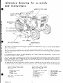
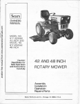
reference drawing for assembly
and instructions
MOWER CLUTCH CABLE
CLUTCH LEVER
another free manual from www.searstractormanuals.com
{mower}
REAR PIVOT
LINK
R.H. GEAR BOX
R.H.
DEFLECTOR SHIELD
MOWER HOUSING
FIG. 1
Thi s tractor or attachment has been designed, engineered and manufactured to give you the best possible dependabi I ity and performance.
Should you experience any yroblem you cannot ~?S i Iy remedy, plea~e contact 'y?ur nearest Sears Roebuck or Sim.psonsSears, Ltd. Service Dept. They have well qualified, competent trained technicians and the proper tools to service or
repair this unti.
It is important that the operator ALWAYS OBSERVES THE "RULES FOR SAFE OPERATION" as well as other
instructions contained in these manuals.
Your new rotary mower attachment utilizes multiple sharp cutting blades rotating about vertical shafts within the
housing. These blades rotate at 14,000 feet per minute. The blades slice grass at approximately 158 miles per hour
to provide a uniformly !=ut lawn. Grass clippings are exhausted through the mower discharge area by the fast flow
of air created by the revolving blades.
The Rotary Mower has been shipped from the factory partially assembled, for shipping purposes. All parts necessary
to complete assembly are included in plastic bags within the carton. The bags of parts include the following items:
Use this bag of parts to mount
mower to tractor without mower
clutch lever
Use this bag of parts to mount
mower to tractor with mower
clutch lever attached
* 1 Blade Clutch Lever
1 Handle Grip
1 Spring
1 Clutch Decal
Items with * are used in both
applications
3828R-8.1.73
2 Blade Safety Drive Washers
1 Spring
* 1
Pulley Guard Guide
2 Rivet Pins
* 2 Retainer Springs
* 2 Bush ings
* 6 Hex Bolts
·2-
* 2
Carriage Bolts
* 1 Rd. Hd. Mach. Screw
* 7 Flat Washers
* 9 Lockwashers
* 7
Hex Nuts
2 Cotter Pins
table of contents
GUARANTEE
ASSEMBLY INSTRUCTIONS
3-6
OPERATING
7-8
MAINTENANCE
8-9
REPAIR PARTS
10-14
another free manual from www.searstractormanuals.com
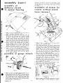
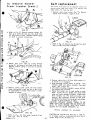
FIG.3
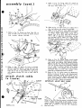
4. Refer to Fig. 3. Assemble lifter bracket (E) to
R.H. side of tractor frame (C) as shown. Secure
I ifter bracket to tractor frame with 1-3/8 x 1
hex bolt, (head to outside) lockwasher, and hex
nut provided. Leave bolt loose.
5. Refer to Fig. 2. line up rear hole of quadrant
(F), L.H. tractor frame (C), and mounting channel.
Secure with a 3/8 x 1 hex bolt, and lockwasher
provided.
6. Remove punch (D) or s im iii ar tool from front
hole of quadrant (F), and secure with a 3/8 x
1 hex bolt, and lock washer provided.
7. Depress button (A) (Fig. 2) on top of lever, and
move lever forward and backward. Then tighten
all 3 bolts ses;urely.
assembly
Assembly as well as all of the different sections of
this Owners Manual should be studied very closely
before beginning to assemble your Rotary Mower.
A letter in parentheses in the following instructions
refers to an arrow in an adjoining Figure (i Ilustration),
unless otherwise stated. When R.H. (Right Hand) or
L.H. (Left Hand) is used, it means from a position
behind the steering wheel a s if one were seated on
the tractor seat and facing forward.
1. Cut all wires, remove mower, plastic bags, and
other parts from carton. Plastic bag contains
parts, and hardware necessary for the assembly
of mower. Layout parts for assembly, and separate bolts etc. according to size.
.~--~
assembly of lift
lever to tractor
,
B------""-
FIG.2
2. Refer to Fig. 2. Depress button (A) on top of lift
lever, and move lift lever to center of quadrant
(F). Release button, lever will lock in notch ().f
quadrant. NOTE: Make .sure threads in mounting
channel are free from paint.
3. Refer to Fig. 2. Position lift lever assembly
(B), under tractor (C) with lever to left hand
side of tractor. Raise the lift lever assembly
into position, so that quadrant (F) will be outside
of tractor, and mounting channel (With threads)
will be inside tractor frame. line up front hole
in quadrant, L. H. tractor frame, and mounting
channel. Insert punch (D) (or similiar tool) to
keep holes in line.
3828R-8.1.73
FIG.4
8. Refer to Fig. 4. Remove belt guide (G) from
around eng ine pu Iley. Some tractors have two
bolts holding belt guide (G) to engine, and some
have only one. If belt guide is also fastened to
muffler. It will be necessary to loosen bolt (H)
in belt guide bracket at muffler to swing belt
guide away from engine pulley.
-3-
. .'
~
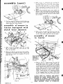
asselT,lbly (cont.)
Normally the wheels should be assembled to the
bottom hole. Thi 5 wi II give a normal cutting height
of approximately 1·7/8 inches. See Fig's. 21 and
22, Page 7.
assembly of
deflector shield
to mower housing
assembly of mower for
tractor without clutch
another free manual from www.searstractormanuals.com
lever (mower)
A
FIG. 5
1. Refer to Fig. 5.· Remove bolt (A) from rear of
mower housing (discharge end).
2. Make sure chain links are not kinked, and slip
shield (B) over discharge end of mower housing
as shown. Replace bolt (A) (head to inside)
through mower housing and shield (B). Slip a
11/32 x 11/16 x 16 Ga. washer (found in plastic
bag) on bolt. Secure with lockwasher, and hex nut,
which was previously removed. Leave bolt loose.
3. Insert a 5/16 x 3/4 carriage bolt (C) (head to
inside) through front of mower housing, and
shield (B). Secure with a 11/32 x 11/16 x 16 Ga.
washer, lockwasher, and hex nut. Bolt washers,
and hex nut will be found in plastic bag.
4. Insert a 5/16 x 3/4 carriage bolt (0) (head to
inside) through top center of housing and shield,
in same manner as step 3 above. NOTE: Be sure
shield is down against mower housing. Tighten
all 3 bolts securely.
assembly
of gauge
FIG. 7
1. Refer to Fig. 7 . Remove nut (A) from end of
wheels
control arm assembly (B).
2. Slip rubber handle grip (C) found in plastic bag
(which contains small spring and decal) over end
of blade clutch handle (0). Place blade clutch
handle (0) on end of control arm assembly (B).
NOTE: There are two flat positions on control
arm, ,be sure flat portion of clutch handle fits
over flat portion of control arm assembly. Replace
hex nut (A) and tighten securely.
3. Remove spring clip (E) holding clutch cable (F)
to front mower housing mounting weldment (G),
and remove cable (F) and discard. This cable is
u~ed on Iy wh en mower is u sed on a tractor
equipped with a clutch lever (rlower).
4. Assemble small spring (H) found in bag with
decal to housing mount assembly (J) and to control
arm assembly (K) as shown.
5. Place mower drive belt (L) on pulley (M) of cross
shaft and on idler pulley (N) as shown.
6. Rotate "'lade clutch handle (0) forward.
FIG.6
1. Refer to Fig. 6. Assemble gauge wheels (A) to
gauge wheel bracket (B). NOTE: Thicker portion
of wheel hub must be toward gauge wheel support
(B). A bushin9 must be inside each wheel hub,
and a 3/8 x 7/8 x 14 Ga. washer must be on each
side of wheel. Secure with a 3/8 x 2% hex bolts,
3/8 lockwasher, and 3/8 hex nut.
3828 R-8.l .73
FIG. 8
7. Remove paper backing from underside of clutch
decal and apply to mower hous,ing as shown.
-4-
3. Refer to Fig. 11. PI ace belt (G) on pulley (H)
of cross shaft, and on idler pulley (J) as shown.
Assemble largest spring (K) from idler bracket
(C) to mounting angle rear (l) as shown. IMPOR·
T ANT: long hook of spring (K) must be to idler
bracket (C) and hook end away from belt (G) as
shown.
4. Refer to Fig. 10. Rotate blade clutch handle (E)
forward. lock in that position, by inserting screw
driver or similar tool, back of handle (E), through
hole in pulley guard (M), and back of idler bracket
(C) as shown.
assembly {cont.}
another free manual from www.searstractormanuals.com
FIG.9
8. Turn front wheels of tractor to the left. Make sure
front pivot I inks (0) are forward as shown. 51 ide
mower under R.H. side of tractor. .
assembly of mower to
tractor equipped with
clutch lever {mower}
A
5. Refer to Fig. 12. Make sure front pivot links (N)
are forward as shown. With front wheel s turned
to left, slide mower under R.H. side of tractor.
assem bly of mower
to tractor
1. Refer to Fig. 10. Assemble clevis (A), on cable
(B), to idler bracket (C), with rivet pin,
cotter pin provided.
and
2. Remove nut (D) from end of control arm assembly.
Slip blade clutch handle (E) found in plastic bag
with decal on control arm assembly (F) and replace nut (D).
BELT GUARD
REMOVED TO
SHOW BEL T
.AND ENGINE
PULLEY
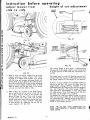
6. Refer to Fig. 13. Thread mower drive belt (G)
up through tractor frame to engine pulley (0).
NOTE: Belt guard can be pulled out far enough
so that belt will pass between guard and engine
pulley. Replace belt guide (P) on engine around
pulley. Make sure bolt or bolts are replaced and
tightened, depending on tractor model. IMPOf<T ANT: There must be 1/8" clearance between
fingers on belt guide and drive belts when clutches are engaged (belts are tight). NOTE: Belt
guard is removed to show belt and engine pulley.
ALWAYS KEEP ALL SHIELDS, AND SAFETY
DEVICES IN PLACE. NEVER DIRECT DISCHARGE OF MATERIAL TOWARD BYSTANDERS, OR BUILDINGS. NEVER ALLOW ANYONE
NEAR MACHINE, WHILE IN OPERATION.
FIG. 11
3828R-8.1.73
-5-
9. Refer to Fig. 16. Swing cable (U~ arol~nkd (so)
that it will be between R.H. front pivot In
N
and R.H. front tractor tire.
assembly (cont.)
\~
\
I
another free manual from www.searstractormanuals.com
~~\
10. Refer to Fig. 17. Insert rivet pin in cable clevIs
(A), and secure with cotter pin provided.
11. Refer to Fig. 16 & 17. Slip cable clevis (A)
with pin on clutch lever (mower) (V) on tractor,
as shown. Attach clutch cable anchor (W) to
gusset Fig. 16 on R.H. foot rest of tractor,
with a 3/8 x 1 hex bolt, lockwasher, and hex
nut provided. NOTE: Make sure cable anchor
(W) hangs straight down as shown. Tighten bolt
securely. Make sure hex nuts on cable are tight
against cable anchor.
7. Refer to Fig. 14. Attach two front I inks (N), to
pins on each side of tractor as shown. Secure
with retainer springs provided.
\
FIG. 18
12. Refer to Fig. 18. Rotate blade clutch handle
(E) forward, and remove screwdriver or similar
tool, which was holding idler bracket forward.
Remove nut (D), Fig. 18 and blade clutch handle
(E), Fig. 10 from control arm assembly. Replace
nut on shaft to protect threads. Save blade
clutch handle. This handle will be used as
mentioned above to hold idler bracket whi Ie
removi ng or assembl i ng mower to tractor.
13. Refer to Fig. 18. Lower mower by depressing
button on top of lift lever, and moving lever
forward. Assemble pulley guard guide (X) to
tractor frame as shown. Secure with round head
mach. screw (head to inside), lockwasher, and
hex nut provided. Tighten nut securely.
8. Refer to Fig. 15. Move lift lever to forward
position. Remove retainer springs (R) from end
of pivot shaft (T). Slip lower ends of rear pivot
links (S) on end of pivot shaft (T), and secure
with retainer springs (R), one on each side of
tractor.
attach clutch
to t ra ctor
/
cable
o
IMPORTANT: ADJUST BELT GUIDE
Q) N----+-~
1/4"
~
~.
3828R·8.1.73.
• 6·
Refer to Fig. 18A. After the mower is attached to the
tractor, engage mower blade clutch handle. Tractor
engine must be stopped. Note the position of belt
guide (A), in relation to the belt (B). Clearance
must be ~ inch.
instruction
before operating
height of cut adiustment
adiust mower from
side to side
GAUGE
WHEEL.
CUTTING
:A~~
\
/'
.........
"
/
I
\
(
another free manual from www.searstractormanuals.com
\
- --- -
r
APPROX.
HEIGHT
OF CUT
\
\
"
""--........
- ---
FIG. 19
../ /
FIG. 21
APPROX,
HEIGHT
OF CUT
ADJUSTMENT
L.IFTER
ARM
FIG. 22
,- --
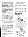
The cutting height of this mower is determined by
the position of the gauge wheels on the cutter head
or by the po sition of the I ifter arm. See Figures 21
and 22.
FIG. 20
1. Refer to Figs. 19 and 20. Inflate tires to recom-
The cutter head is of the full floating type and will
closely follow the contours of the ground when using
the gauge wheels for the height of cut position.
mended pressures. Place' tractor, with mower
mounted on a smooth level surface. Lift mower
with lift lever until runners and gauge wheels are
off the level surface. Measure the distance down
from rear of housing (A) (at rear runner attaching
points) to level surface. Distance down on both
ends of mower must' be the same. If not mower
will not cut level from side to side.
However, if gauge wheels are suspended slightly no
tearing of the turf will occur on sharp turns by
gauge wheels sliding sideways. Therefore it is recommended that the I ifter arm be used for height of
cut, see Figure 22, and adjust gauge wheels to
clear ground by approximately Y2 inch, see Figure
21,when tractor is on level ground and lifter arm
has been set to height of cut desired.
~ 0 operate the I ifter arm depress button on top of
lifter arm and move lifter arm to desired height of
cut, see Figure 22. Release button so that pin will
engage desired notch in lifter quadrant. This locks
mower in that height position.
2. Refer to Fig. 20. If mower is not level, loosen
jam nut (B) on sq. hd. set screw in R.H. lift arm
(C). If R.H. side of mower is low un screw set
screw (D) from lift arm. If R.H. side of mower
is high screw set screW down into lift arm.
Adjust screw until both sides of mower are level
(same distance to level surface). Then lock
in that position by tightening jam nut (B) securely against lift arm (C).
READ "RULES FOR SAFE OPERATION" ON
PAGE ONE CAREFULLY BEFORE OPERATING
YOUR MOWER.
3828R-8.1.73
-7-
~
.~
OPERATING
INSTRUCTIONS
4. Make left hand turn s when mowing, this spreads
the grass clippings evenly over the grass which
has been cut. Grass is mowed regularly (do
not let grass get too high), there is little or
no raking necessary after mowing.
BEFORE CUTTING AN UNFAMILIAR PLOT OF
GRASS, ALWAYS STOP TO ANALYZE THE
LAWN OR FIELD FOR BEST MOWING PROCEDURE. CONSIDER ALSO THE HEIGHT OF
GRASS TO BE MOWED. TYPE OF TERRAIN
(LEVEL, HILLY OR PITTED), AS WELL AS
THE PRESENCE OF ROCK OR TRASH. EACH
CONDITION WILL REQUIRE CERTAIN ADJUSTMENTS OR PRECAUTIONS AS OUTLINED IN THIS MANUAL.
another free manual from www.searstractormanuals.com
/
WHEN MOWING NEXT TO BUILDINGS OR
FLOWER BEDS THE TRACTOR SHOULD BE
DRIVEN SO THAT THE DISCHARGE OF MOWER
WILL BE AWAY FROM BUILDING OR FLOWER
BED.
Do not shift gears while going up steep hi lis.
Choose a low enough gear to cI imb h ill without
stopping and shifting gears. If it is necessary
to stop while going up hill, do so quickly to
prevent tractor roll ing backward. When start ing
tractor in motion going up hill, use one of the
lowest gears, reduce engine speed and engage
clutch gradually to prevent tractor from "rearing
up".
I
DO NOT STOP OR START SUDDENLY WHEN
GOING UPHILL OR DOWNHILL. OPERATE
MOWER UP AND DOWN THE FACE OF SLOPES;
NEVER ACROSS THE FACE. NEVER OPERATE
MOWER ON SLOPES WITH MORE THAN A 15
DEGREE SLOPE.
The blade clutch handle is located at right hand
of mower on cutter head or on R.H. side of tractor
frame depending on tractor. The blade clutch handle
engages the mo wer bl ades.
maintenance
lubrication
1. Set engine speed to about half throttle before
engaging or disengaging mower. In either case,
engage or disengage blade .clutch handle slowly.
After mower is engaged, set to full throttle.
Caution: Never engage mower except when sitting on tractor seat, and keep hands and feet
from beneath the housing. After mower is engaged, advance throttle lever to full throttle.
2. Push down on foot pedal and move gear shift
lever to speed desired. Normal cutting speed is
1st gear on a three speed custom tractor, 2nd
gear 011 a four speed cu stom tractor, or 3rd gear
low range on a eight speed custom tractor. If
engine pulls down, shift to a lower gear on four
and eight speed tractors, and cut less than a
full width cut on a three speed custom. In extreme heavy cutting it may be necessary to use
the lowest gear and take a narrower cut.
FIG. 23
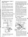
1. Check grease in gear boxes after each fifty
hours of operation. Each gear box shou Id be
approximately Y2 full.
Lubrication - Gear case moly E.P. lithium
grease 4 oz. required in each gear box. Can be
purchased from Sears automotive department.
2. To check, remove gear box cover by unscrewing
4 screws. See Figure 23.
Do not operate the tractor in high gear going
down hill', and do not turn sharp corners while
going down hill. If it is necessary to stop tractor
while going down hill, do so quickly to prevent
tractor from picking up speed during the declutching to braking operation. NOTE: The
engine produces considerable braking action
when throttled back to idling speed without declutching, and this procedure is recommended
before applying brake.
3. Refer to Page 6, Fig. 16. Lubricate cable with
light oil, twice a year.
3. Normal cutting height is '1-7/8 inches, height of
cut can be adjusted by means of lift lever. Moving the lever forward lowers the mower wh i Ie
moving it backwards raises the mower. '
With lift lever set to height of cut desired and
with tractor and mower on level ground, adjust
gauge wheel s so that they c lear the ground by
approximately Y2 inch.
3828R-8.1.73
-8-
maintenance {cont.}
Threads on shaft are R.H. Remove spring washer,
and slip blade from blade safety drive washer. Remove bl ade safety washer and sh i eld from sh aft and
examine. I F DAMAGED, REPLACE. TWO EXTRA
BLADE SAFETY DRIVE WASHERS WERE SHIPPED
WITH MOWER. Reassemble shield, blade safety
drive washer, blade, spring washer, and nut. Tighten
nut securely. NOTE: REFER TO FIGURE 24 FOR
SEQUENCE OF REPLACING BLADE.
blade care
i
For best results, cutting blade must be kept sharp.
The blade can be sharpened with a few strokes of
a file, or on a grinding wheel. Do not attempt to
sharpen
while on mower.
another free manual from www.searstractormanuals.com
When grinding, care should be taken to maintain
blade balance and the blade should be checked for
proper balance before re-installation on mower.
Imbalance of blade or bent blade will cause excesssive vibration when runn ing, and/ eventual damage
to mower or engine.
,I
cleaning
To insure satisfactory operation, it is recommended
that before the start of each mowing season, the old
blades be discarded and replaced with new blades.
Mower blades can be ordered at all Sears retai I
stores and mail order outlets.
CAUTION: BE SURE TO REMOVE ENGINE SPARK
PLUG WIRE BEFORE ATTEMPTING TO REMOVE
BLADE.
blade
safety
drive washer
Thi s mower has a blade safety drive washer on
each blade shaft. This is a soft piece between
blade and shaft so engineered that if the blade
strikes a solid object this blade safety drive washer will break, preventing damage to expensive shaft
or mower blade.
Water pressure from a garden hose can be used in
cleaning underside of housing, if cleaned immediately after use before clippings under mower have a
chance to dry out.
For cleaning underside of mower that has dry packed
clippings place tractor in gear or engage parking
brake. Jdck up front of tractor and clean underside
of mower with putty knife or similiar tool. IMPORTANT: Raise front end of tractor using a Sears
special riding tractor jack, or a substantial block
under each front wheel, and block up, mower attachment so that there is no possible way for mower or
tractor to fall. Mower attachment may be removed
from tractor for cleaning. Clean underside of mower
with putty knife or similiar tool.
Thi s should be done whenever an accumulation of
grass builds up under mower. Mower will do ~ much
better job of mowing it underside of mower IS kept
clean.
to remove mower
from tractor
Two extra blade safety drive washers are shipped
with each mower, and can be found in the plastic
bag with other small parts and Instruction Book.
®..
mower
1. If tractor is equipped with clutch lever (mower)
mounted on tractor. Refer to Figures la, Page
5. Use steps 2 and 4. This will lock idler arm
forward so that mower can be easi Iy removed.
2. Refer t~ Page 4, Fig. 8. When clutch lever is
on the mower, push blade clutch handle forward
to "stopped" position.
NUT
fO\---SPRING
~.
WASHER
G
/e
BLADE SAFET'~.®
-DRIVE WASHER~
~SHIELD
i--'..,..:r.--
A
FIG. 24
blade
replacement
BEL T GUARD
REMOVED TO
SHOW BEL T
AND ENGINE PULLEY
FIG. 25
1. Mower can be removed from tractor to replace
blades. Wedge a wood block between blade ~nd
mower housing to hold mandrel from turning
when removing nut holding blade.
3828R-8.1.73
_9 -
FIG. 26
3. Refer to Fig. 26. Remove belt guide (A) from
around engine pulley. Some tractors have two
bolts holding belt guide (A) to engine, and Some
have only one. If belt guide is also fastened to
muffler. It will be necessary to loosen bolt (H)
(Page 3, Fig. 4L in belt guide bracket at muffler
to swing belt guide away from engine pulley.
Remove belt from engine pulley. Push belt down
through tractor frame. Belt guard can be pulled
out far enough for belt to pass between guard
and engine pulley.
to remove mower
fro m tractor (cont.)
~
belt replacement
The mower drive belt can be replaced without removing mower head from mower if so desired. See
steps below for removing belt.
\
another free manual from www.searstractormanuals.com
1. Remove mower from tractor. See "To Remove
Mower From Tractor", pages 9 & 10.
FIG. 27
4. Refer to Fig. 27. Remove retainer spring,s (D)
from pivot shaft (E) and slip rear pivot links
(K) from ends of shaft. Replace retainer spring
on shaft to prevent losing them.
~11\
FIG. 31
2. Refer to Fig. 31. Remove two E rings from both
ends of shaft and pulley assembly.
G
~~\\~~n~n nnn nOf7
.<'-«\
FIG. 28
5. Detach front pivot links by pulling retainer
spring (F), and remove links from pivot pin (G).
Replace retainer spring in pivot pin to prevent
losing it.
FIG. 32
3. Remove cable clevis (K) from idler bracket (L)
if mower is so equipped.
4. Slide couplings toward center of mower. This
releases shaft and pulley assembly from gear
boxes. See Figure 32.
5. Lift shaft and pulley assembly, remove old belt
and replace with new belt.
6. CheCk that blades are at right angles to each
other. If they are not, blades will strike each
other and cause damage to blades, blade safety
drive washers, etc. Put shaft and pulley into
position. Slip couplings outward So that shaft
and blade drive boxes are connected and replace
E-rings to lock couplings in place.
CAUTION: RECHECK BLADE TIMING TO BE
SURE THAT THE BLADES ARE AT RIGHT ANGLES TO EACH OTHER. REATTACH CABLE
CLEVIS (K) TO IDLER BRACKET (L).
6. Remove pulley guard guide (H) from tractor
frame. Save guide, screw and nut so that it can
be reassembled to frame when mower is reassembled
Reverse
7. Refer to Fig. 30. Slip mower housing (J) out
from R.H. side of tractor.
3828R-8.1.73
- 10-
procedure
for
reassembly
CAUTION: Be sure felt disc (Key No.3, page 11),
is in proper position. Lubricate felt disc with a
couple drops of No. 30 motor oi r.
•
repair
parts
another free manual from www.searstractormanuals.com
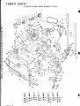
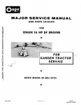
38" ROTARY MOWER--MODEL NUMBER 917.252031
-24
,
25-+
I
5
Q'
,
,
®,~81
E(e==~e~ __ 82
I
A.
G
.B5--§~_B3
,
~-84
1---28
~--27
ABC
0
E
F
G
H
iii Iii • ,
®87 @88 ~28 ~ 88 ~28 ®90 @88 ®90
®87 ® 89 ®84 @89 ®84 ~88 ® 89 @88
@86
®89
@89
3828R·8.1.73
- 11 -
o
•
repair
parts
i_
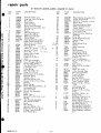
38" ROTARY MOWER--MODEL NUMBER 917.252031
KEY
NO.
another free manual from www.searstractormanuals.com
)J
(e
PART
NO.
1
2
3
4
5
6
_. 7
794042
786028
788039
2037R
5231H
776085
792027
8
9
10
11
12
13
14
786059
794041
511P
626A271
7717H2
626A355
974R
15
16
17
18
19
20
21
22
23
24
25
26
27
28
29
30
31
32
33
34
35
36
...].a..
39
40
41
42
43
44
45
4939M
957R
1563R
2259R
2292R
2547R
2895H
2503P
1053R
626A360
626A336
2540R
3091P
1004P
2876H
9465M
2505P
626A358
4940M
3848R
3199P
1556P
7375H
9536H
626A283
1004P
515P
626A342
2510R
3827R
2537R
46
47
48
49
50
51
52
53
626A372
548P
3382R
1342R
3257P
1545P
5002P
4379H
.-'lL
3828R-8.1.73
DESCRIPTION
Head Assembly L.H.
Coupling, Input Connector
Disc, Felt
Wiper Sleeve
Crescent Ring
Shaft, Input Connector
Set Screw, Knurled Hd. c.P.
5/16-24 x W
/
Sheave /
Head Assembly R.H.
Nylock Nut 3/8-24
Blade Clutch Handle
Pulley Guard
Housing Mount Assembly
Blade Clutch Spring (For
when lever is on mower)
Retainer Spring
<;('qrrlJ~r
Pivot Shaft
V-Belt <4.... B'Jj7 /1} loG
Spring Clip ")IJ?;
.'
Rivet Pin J5
3 X (j
Mower Clutch Cable
Handle Grip
Cotter Pin 3/32x %
Decal
Lifter Arm Assembly
Lever Plunger & Button
Clutch Cable Anchor
Hex Bolt 3/8-16 xl H.T.
Lockwasher 3/8
Lifter Spring
Roll Pin 3/16 x 172
Cotter Pin 1/8 x %
Connecting Link Assembly
Reta i ner Spri ng
Runner L.H.
Hex Bolt 3/8-24 x 2%
Washer 13/32 x 7/8 x 14Ga.
Bushing
Wheel, Gauge
Wheel Bracket Assembly L.H.
Lockwasher 3/8
Hex Nut 3/8-24
Control Arm Assembly
Spacer
Model Plate
Spring (For when lever is on
tra'ctor)
Idler Bracket Assembly
Hex Jam Nut 3/8-24
Decal
Idler Pulley
Hex Bolt 3/8-24 x 1y,j
Washer 17/32 x 1 x 16 Ga.
E-Ring Truarc 5133-50
Shift Handle Grip
KEY
NO.
PART
NO.
54
55
626A284
8310H1
626A356
960R
3538R
3239R
2185R
3539R
5050H
626A352
56
57
58
59
60
61
62
63
"
64
65
66
67
68
~ '.=;:;::::t.-
:2' -
'7 if
69
70
71
72
73
74
75
76
77
78
79
80
81
82
83
84
85
86
87
88
89
90
A
B
C
D
E
F
G
H
- 12 -
DESCRIPTION
Wheel Bracket Assembly R.H.
Pulley Guard Guide
Deflector Assembly w/chain
Runner R.H.
Defl ector-Cau ti on Deca I
Safety Standard Sticker
Clutch Decal
Instruction-Caution Decal
Pivot Link Front
Mower Housing Mounting
Weldment
1032R
Pivot Pin
626A286 Blade Shield Assembly
1567R
Mandre I Plate
786044
Shield
1044R
Blade Safety Drive
,.
Washer
759R
Mower Housing
2464R
Blade
9914M
Spring Washer
539P
Nylock Nut 5/8-18
968R
Blade Shield Outlet
4524P
Sq. Hd. Set Screw C.P.
3/8- 16 x 1y,j
626A373 Lift Link Weldment
1577P
Washer 17/32 x 1-1/16 x
13 Ga.
2308R
Bell Crank
1513P
Washer 13/32 x 13/16 x
16 Ga.
2511 P
Cotter Pin 3/16 x 1
626A357 Lifter Arm and Tube
508P
Hex Jam Nut 3/8-16
8720H
Pivot Li nk Rear
5086H
Li fter Bracket
501P
Hex Nut 3/8-16
5000P
E-Ring Truarc 5133-75
545P
Crown Locknut 3/8-16
1557P
Washer 13/32 x 13/16 x
11 Ga.
1003P
Lockwasher 5/16
504P
Hex Nut 5/16-18
1537P
Washer 11/32 x 11/16 x
16 Ga.
3137P
Hex Bolt 3/8-16 x 1y,j
Grade5H.T.
3159P
Hex Bolt 5/16-18 x 7/8
3223P
Slotted Rd. Hd. Mach.
Screw 3/8-16 x %
16P
Carriage Bolt 5/16-18 x %
3023P
Hex Bolt 3/8-16 x 1
17P
Carriage Bolt 5/16-18 x 1
17P
Carriage Bolt 5/16-18 x 1
16P
Carriage Bolt 5/16~~ x %
3828R
Owners Manual and arts
Li st
The Model Number will be found on a plate attached to the'L.H.
side of the housing mount assembly. Always mention the Model
Number when requesting service or repair parts for x.,our 38"
Rotary Mower.
another free manual from www.searstractormanuals.com
ISears I
owners
manual
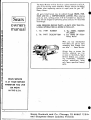
All parts listed herein may be ordered through SE;ARS, ROEBUCK AND CO. or SIMPSONS-SEARS LIMITED. When ordering
parts by mail, selling prices will be furnished on request or
parts will be shipped at prevailing prices and you will be billed
accordingly.
wHEN ORDERING REPAIR PARTS, ALWAYS GIVE THE FOLLOWING INFO'RMATION AS SHOWN IN THIS LIST.
1. The
PART
2. The
PART
NUMBER
DESCRIPTION
3. The MODEL NUMBER
917.252031
'
4. The NAME .OF ITEMRotary Mower
When you buy merchandise'
from Sears you get an extra
something that nobody else
can offer ••• Sears Service.
,
Across town or across the
country, wherev.,er you live
or move in the U.S.A., Sears
Service follows you, providing trustworthy, competent
service technicians USIng
only Sears specified factory
parts.
SEARS SERVICE
IS AT YOUR SERVICE
WHEREVER YOU LIVE
OR MOVE
IN THE U.S.A.
Sears, Roebuck and Go., Chicago, Ill. 60607 U.S.A.
and Simpsons Sears Limited, Toronto
3828R-8.1