1
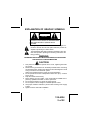
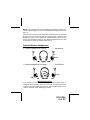
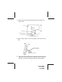
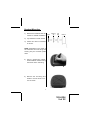
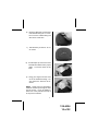
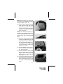
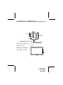
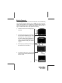
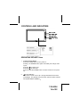
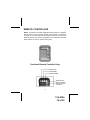
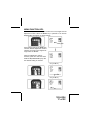
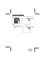
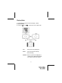
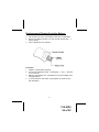
®
ELECT RONICS CORP.
LCM5869NP & LCM7069NP
Remote Controlled Color Display Monitor
5.8-Inch Color Display Monitor
7-Inch Color Display Monitor
Installation and Owner's Manual
Released: 03-27-02.
128-6324
1 of 22
EXPLANATION OF GRAPHIC SYMBOLS
CAUTION
RISK OF ELECTRIC SHOCK
DO NOT OPEN
CAUTION:TO REDUCE THE RISK OF ELECTRIC SHOCK DO
NOT REMOVE COVER (OR BACK) NO SERVICEABLE PARTS
INSIDE REFER SERVICING TO QUALIFIED SERVICE
PERSONNEL
The lightning flash with the arrowhead within a triangle is intended to alert tell the user that parts inside the product are
capable of producing an electric shock .
The exclamation point within a triangle is intended to alert the
user that important operating and servicing instructions are
being provided.
WARNING:
TO PREVENT FIRE OR ELECTRIC SHOCK HAZARD, DO NOT EXPOSE
THIS PRODUCT TO RAIN OR MOISTURE.
CAUTION:
1.
2.
3.
4.
5.
6.
7.
8.
9.
This product is designed to operate with a 12 volt, negative ground battery system.
Disconnect the ground wire from the battery terminal before connecting
the electrical system. Refer to the electrical connection diagram to avoid
wrong connection of the electrical system.
Always use authorized service center for service assistance.
Do not operate the monitor at temperatures below 32°F (0°C) or above
104°F (40°C).
Keep the monitor clean and dry.
Never attempt your own repairs. This unit should be installed and repaired by qualified technicians or service personnel..
Do not drop the monitor or expose to strong impacts.
Do not expose to direct sunlight for extended periods of time.
Use proper insulation material to prevent short-circuiting of the supply
system.
Tighten all loose wires after installation.
1
128-6324
2 of 22
MATERIALS LIST
1.
2.
3.
4.
5.
6.
7.
8.
System Monitor (LCM5869NP=136C2185) or
(LCM7069NP=136C2184)
Remote Control Unit (136B2156, used with LCM5869NP
and LCM7069NP) with Lithium Battery, 3V,CR 2025
Interconnect Box (136B2183, used with LCM5869NP and
LCM7069NP)
Monitor Cable, 8' (112B3151, used with LCM5869NP and
LCM7069NP)
Headrest Mounting Tray (LCM5869NP=102C3739)
or (LCM7069NP=102B3738)
Trim Ring for Mounting Tray (LCM5869NP=102C3746)
or (LCM7069NP=102B3745)
Power Cable, 2.46' (112B3127, used with LCM5869NP
and LCM7069NP)
Removal Tool (108B3632)
(1pc.)
(1pc.)
(1pc.)
(1pc.)
(1pc.)
(1pc.)
(1pc.)
(1pc.)
!
$
#
"
%
&
2
128-6324
3 of 22
SYSTEM OVERVIEW
The LCM5869NP is comprised of a 5.8" Thin Film Transistor (TFT) Liquid Crystal Display ( LCD) Monitor. The LCM7069NP is comprised of a 7"
Thin Film Transistor (TFT) Liquid Crystal Display ( LCD) Monitor. The
Monitor for both of these systems have a 16:9 Aspect Ratio display that
allows the user to select between two video sources (Not Supplied). The
Monitors display all functions with the comprehensive On Screen Display
(OSD). Can be used with optional one or two channel Wireless Infrared
Headphones.
OPTIONAL AUDIO CONNECTION
Materials Needed for Optional Audio Connection:
Option #1
1) IRT456 (CHA) Infrared Transmitter, Single Channel ............. (1pc)
2) MVIRHS Single Channel (A) Infrared Headphone(s) ............. (1pc)
Option #2
1) IRT457 (CHB) Infrared Transmitter, Dual Channel ............... (1pc)
2) IR2CHS Dual Channel (A/B) Infrared Headphone(s) ............ (1pc)
Before installing the IRT boards gently bend the three IR LEDs closest to
the center of the vehicle toward the center of the vehicle.
NOTE: When installing two screens, install one IRT456 Single Channel
Infrared Transmitter into the left Headrest Mounting Tray and one IR2CHS
Dual Channel Infrared Transmitter into the left Headrest Mounting Tray.
IRT 456 CH A BEFORE
IRT 456 CH A AFTER
IRT 457 CH B BEFORE
IRT 457 CH B AFTER
3
128-6324
4 of 22
NOTE: The following IRT board installation procedure should be performed between steps 10 and 11of the Headrest Mounting procedure on
page 10.
Insert the IRT boards into their respective compartments in the Headrest
Mounting Tray and insert the plug into the IRT board. When the user
switches the video source utilizing the ON/OFF/MODE switch, the A/B
switch (see illustration below) on the IR2CHS Headphones must also
be switched to select the desired audio source.
Optional Wireless Headphones:
1)
Wireless Headphones (1 Channel) ....................... P/N =MVIRHS
AUD
ARE
DH
IO
OX
AUD
EADP
HON
ES
INFR
ARE
IO
DH
OX
PHO
EAD
NES
R
P OWE
OFP OW
F ER
ON
INFR
VO
L
1) Wireless Headphones (2 Channel) .................. P/N =IR2CHS
C H.B
C H.A
AUD
INFR
ARE
D HEA
IO
OX
AUD
DPHO
ARE
INFR
IO
D HEA
OX
S
ONE
DPH
R
P OWE
ER
POW N
OFF-O
OFP OW
F ER
ON
NES
VO
L
IMPORTANT NOTICE
It is unlawful in most jurisdictions to drive a motor vehicle which is
equipped with a television viewer or screen that is located at the point
forward of the back of the driver’s seat, or that is visible directly or indirectly, to the driver while operating the vehicle.
4
128-6324
5 of 22
VEHICLE PREPARATION
1) Decide on the system configuration and the options that will be installed (i.e. what components, VCP, DVD, TV Tuner, Video Game,
Monitor, FM Modulator, etc.).
2) Read the manuals and get familiar with the electrical requirements
and connections.
3) Decide on the mounting locations and methods of mounting the products.
4) Prepare the vehicle by removing any interior trim necessary to gain
access to the vehicle's wiring as well as all areas where interconnecting wire harnesses will be located. If any access holes need to be cut
into the vehicle, headrests, or other trim components, this should be
performed now. (Refer to the Installation Procedure).
5) Run the wiring harnesses and cabling throughout the vehicle as necessary. (Refer to the wiring instructions for the individual components
and accessory options being installed). Be sure, that all the wiring is
protected from sharp edges and is routed in such a manner that it will
not be pinched, when it is fully installed. Be sure to leave enough
slack in the wiring at each component to allow sufficient working
room.
6) Remove all the A/V system components from their packaging and
then place them in the vehicle at their respective locations.
7) Locate an accessory power source (Red Wire)(+12VDC present when
the ignition key is in the accessory and run positions. 0VDC should
be present, when the ignition key is in the OFF position). Generally,
these wires can be found at the ignition switch or fuse box.
8) Locate a Constant Power Source (Yellow Wire)(+12VDC present at
all times).
NOTE: Ensure that the accessory power is fused at the source.
Failure to do so may result in vehicle wiring damage.) Ground the
black wire to a chassis ground close to the mounting location of AV
sources.
9) Connect all the components together (electrically) and verify that the
proper operation of all the system functions. NOTE: This is best
done BEFORE the components are permanently mounted.
5
128-6324
6 of 22
10) After verifying the proper operation of the system, proceed to mount
each component.
11) The mounting method, and the location will vary from vehicle to
vehicle; this manual will focus on typical Headrest installation procedures.
12) The best location for the system components is:
a) Monitor: Headrest or bracket (optional) mounted onto a
flat surface.
b) System Interconnection Box (AVX-6869): In line with all the
system cabling and in an area where it can be easily accessed.
c) System Main Cable: Under either seat where monitors
are located.
Tools and Materials Required:
Utility knife or box cutter with sharp blade.
Permanent Marker.
Tie Wraps.
INSTALLATION
Mounting with Optional Bracket:
This procedure describes mounting the system monitor using an optional Surface Mount Bracket (sold separately, P/N FB1)
1)
Start by firmly attaching the Surface Mount Bracket onto a clean flat
surface.
6
128-6324
7 of 22
2) Slide monitor onto Surface Mount Bracket and then tighten the
fasten wheel.
Monitor
Fastener Wheel
Surface Mount Fastener
Mounting Bracket
3) Adjust viewing angle of monitor by tightening the fastener at the
side.
Surface Mount
4)
When the system components are mounted, test the system to
verify that it is functioning correctly. Make sure that no wiring was
pinched, or connected improperly during the final installation.
7
128-6324
8 of 22
Headrest Mounting:
1)
Remove the headrest from the
vehicle for easiest installation.
2)
Lay headrest on a flat surface.
3)
Center trim collar on headrest
as shown.
Monitor
Mounting
Tray
Trim
Ring
Headrest
NOTE: Depending on the angle of
the headrest the Trim Ring and
housing may be mounted upside
down.
4)
Using a permanent marker,
mark headrest material along
the interior of the Trim Ring.
5)
Remove the Trim Ring and
mark an “X” from corner to corner as shown.
8
128-6324
9 of 22
6)
Using the utility knife, cut the headrest material along the “X” lines.
Do not cut the material along the
other lines at this time.
7)
This will leave you with an “X” cut
as shown.
8)
Pull the flaps up and cut the foam
beneath the material to the proper
depth. Cut all four sides of the
foam.
9)
Using your fingers, tear the foam
out of the headrest leaving a recess where the shell will be inserted.
NOTE: At this point you will need to
install the harness up through the area
into the recess. It may be helpful to
follow one of the posts and tie wrap it
to the post for restraint.
9
128-6324
10 of 22
NOTE: The Mounting Tray will need to
be secured to the headrest, either by
using tie straps, screws, etc.
10) Lay the flaps of headrest material
down into the recess and insert
the Mounting Tray into the recess.
Check for fit. If it does not fit properly, you may need to remove
some more foam.
NOTE:If an Infrared Transmitter (optional) is to be installed it must be connected at this point as shown. This
must be done prior to the following
steps
11) Guide the cable through the side
opening of the Mounting Tray and
plug it into the Monitor. Make sure
the connector locks into place. Insert the Monitor into the Mounting
Tray and secure the cable using
tie wraps or screws
12) Turn the Monitor around and insert it into the Mounting Tray housing. Snap into place.
13) Connect the Monitor power input
plug to a DC power source (Red
plug +12 VDC, Yellow plug +12
VDC Constant and Black plug (-)
to ground).
14) Connect the external video source
output signal (from VCP/DVD, TV
Etc.) to the VIDEO IN jack. Test
the system to verify proper installation.
10
128-6324
11 of 22
ELECTRICAL CONNECTION (Wiring Diagram)
AV Output
Video Source
Input (1&2)
Not Used
AUDIO OX
11
128-6324
12 of 22
Monitor Removal:
The following procedure is to remove the Monitor from the Mounting
Tray using the supplied Removal Tool. NOTE: Use care when performing this procedure not to scratch any exposed surfaces with the
edges of the Removal Tool. Masking tape applied to the two tips or
legs of the Removal Tool will help prevent scratching.
1)
Locate the Removal Tool and apply tape
to the tips.
2)
Insert the Removal Tool into the center of the space between the top outer
Mounting Tray and the Monitor. You
will hear click(s) when inserted correctly. This will disengage the two
pressure latches holding the monitor
in place.
3)
While applying upwardly pressure, pull
the Removal Tool out and up.
4)
The Monitor will pop out from the top
and can be removed by detaching the
Monitor Cable.
Removal
Tool
Removal Tool
!
Removal
Tool
"
Monitor
Cable
12
128-6324
13 of 22
CONTROLS AND INDICATORS
Headphone
AUDIO OX
OPERATING INSTRUCTIONS
1.
POWER ON/OFF/MODE
Press the POWER button to turn power on.
Pressing the POWER button again momentarily will change video
inputs.
for NTSC input.
Press the
Press the
for PAL input.
Press and hold the POWER button for three seconds to turn power
off.
2.
Scroll Up Button
This button is used to move Up through theselected menu items
(Color,Bright, Tint, [NTSC] Only) this button will also switch selected
items (DIM, RESET, FORMAT).
13
128-6324
14 of 22
3.
Scroll Down Button
This button is used to move Down through the selected menu
items (Color, Bright, Tint, [NTSC] Only) this button will also switch
selected items (DIM, RESET, FORMAT).
4.
MENU Button
Press the MENU button once to display the menu On Screen
Display.
Press the button again until the desired menu item is highlighted.
Use the
or
to adjust or switch the selected item. The On
Screen Display menu will disappear if no buttons are pressed for
four seconds.
MAINTENANCE
To avoid electrical shock, do not open the enclosure. High voltage is
present. No user serviceable parts inside the enclosure.
Do not use any chemical solvent, cleaning agent or corrosive detergent to clean away dirt on the surface of the screen. To clean off dirt or
fingerprint, we recommend the use of a soft damp lens cleaning cloth.
Should there be requirement to replace blown fuse, do remember to
disconnect all power supply and switched off the unit before replacing
it with a new one. Only use fuse’s with a correct rating to avoid damaging the unit.
14
128-6324
15 of 22
REMOTE CONTROLLER
NOTE: The Remote Controller supplied with this system is a standard
remote control, which is used to operate other systems. The Remote
Controller is not a universal remote and will only perform the functions
described herein. Only the Keys highlighted on the Remote Controller
image bellow are used to operate this system.
Functional Remote Controller Keys
POWER ON/OFF
UP ADJUSTMENT
DOWN ADJUSTMENT
MODE SELECTION
MENU (ACTIVATION of
OSD and FUNCTION
SELECTION)
15
128-6324
16 of 22
MENU FUNCTION KEY:
The MENU Key is used to navigate between the Color, Bright and Tint
adjustment modes. When the MENU Key is pressed an On Screen
Display(OSD) will appear as shown bellow.
COLOR
BRIGHT
TINT
DIMMER
FORMAT
RESET
OSD
Press release and tap the MENU Key
until the desired adjustment mode is
selected. To return to the original settings select the RESET.
When an adjustment mode is
selected, press and hold the either
the F or G (CH/DISK/SET) Key until
the desired setting is reached.
COLOR
BRIGHT
TINT
DIMMER
FORMAT
RESET
Using the F Key
COLOR
BRIGHT
TINT
DIMMER
FORMAT
RESET
Using the G Key
COLOR
BRIGHT
TINT
DIMMER
FORMAT
RESET
16
128-6324
17 of 22
VIDEO SOURCE MODE KEY:
To switch between Video Input Sources (AV1 and AV2) press and release the MODE Key.
NOTE:
Select either *NTSC or PAL,
press the F or G Keys (CH/
DISK/SET).
17
128-6324
18 of 22
Display Mode
1. Press MENU to get the On Screen Display (OSD).
2. Select FORMAT.
or the
to switch the screen aspect ratio.
3. Press the
FULL:
16:9 picture is fully displayed.
ZOOM:
Picture is stretched vertically
and horizontally.
NORMAL: When 4:3 pictured is displayed on
a wide screen, black bands appear
on the right and left of the picture
18
128-6324
19 of 22
Replacement of Remote Controller Battery:
1.
2.
3.
Use a small coin to pry open battery holder from compartment.
Remove old battery and put in a new one with positive sign “ + “
facing upward.
Push compartment into position.
Precaution:
1. Dispose of used battery properly.
2. Do not misuse battery by short - circuiting the “ + “ and “ - “ terminal
or put it into fire.
3. Remove used battery from compartment to prevent leakage from
damaged battery.
4. To avoid accident, never allow young children to handle or play
with the battery.
19
128-6324
20 of 22
SPECIFICATIONS
LCM5869NP:
LCD Panel Size (Diagonal) .................................
LCD Panel Format ...............................................
LCD Panel Resolution .........................................
LCD Backlight Life ................................................
Image Aspect Ratio ..............................................
Video Input Signal ................................................
Video
Power Source .......................................................
Power Consumption ............................................
Operating Temperature .......................................
Storage Temperature ...........................................
Weight ..................................................................
Dimensions .........................................................
5.8"
1200 x 234 dots
280,800 pixels
10,000 hrs
16:9
NTSC/PAL Composite
+12V
10W
0 C to 60 C
-20 C to 80 C
0.313 kg
15.8 x 97 x 2.9 cm
LCM7069NP:
LCD Panel Size (Diagonal) ...................................
LCD Panel Format .................................................
LCD Panel Resolution ...........................................
LCD Backlight Life .................................................
Image Aspect Ratio ...............................................
Video Input Signal ..................................................
Video
Power Source .......................................................
Power Consumption .............................................
Operating Temperature .........................................
Storage Temperature .............................................
Weight ..................................................................
Dimensions ..........................................................
7"
1440 x 234 dots
336,960 pixels
10,000 hrs
16:9
NTSC/PAL Composite
+12V
10W
0 C to 60C
-20 C to 80 C
0.380 kg
18 x 11 x 2.9 cm
20
128-6324
21 of 22
36 MONTH LIMITED WARRANTY
Applies to Audiovox Mobile Video Products
AUDIOVOX ELECTRONICS CORP. (the Company) warrants to the original retail purchaser
of this product that should this product or any part thereof, under normal use and conditions,
be proven defective in material or workmanship within 36 months from the date of original
purchase, such defect(s) will be repaired or replaced with reconditioned product (at the
Company's option) without charge for parts and repair labor.
To obtain repair or replacement within the terms of this Warranty, the product is to be delivered
with proof of warranty coverage (e.g. dated bill of sale), specification of defect(s),
transportation prepaid, to the Company at the address shown below.
This Warranty does not extend to the elimination of externally generated static or noise, to
correction of antenna problems, to costs incurred for installation, removal or reinstallation of
the product, or to damage to tapes, discs, speakers, accessories, or vehicle electrical systems.
This Warranty does not apply to any product or part thereof which, in the opinion of the
Company, has suffered or been damaged through alteration, improper installation, mishandling,
misuse, neglect, accident, or by removal or defacement of the factory serial number/bar code
label(s). THE EXTENT OF THE COMPANY'S LIABILITY UNDER THIS WARRANTY IS
LIMITED TO THE REPAIR OR REPLACEMENT PROVIDED ABOVE AND, IN NO EVENT,
SHALL THE COMPANY'S LIABILITY EXCEED THE PURCHASE PRICE PAID BY PURCHASER FOR THE PRODUCT.
This Warranty is in lieu of all other express warranties or liabilities. ANY IMPLIED
WARRANTIES, INCLUDING ANY IMPLIED WARRANTY OF MERCHANTABILITY, SHALL
BE LIMITED TO THE DURATION OF THIS WRITTEN WARRANTY. ANY ACTION FOR
BREACH OF ANY WARRANTY HEREUNDER INCLUDING ANY IMPLIED WARRANTY OF
MERCHANTABILITY MUST BE BROUGHT WITHIN A PERIOD OF 48 MONTHS FROM DATE
OF ORIGINAL PURCHASE. IN NO CASE SHALL THE COMPANY BE LIABLE FOR ANY
CONSEQUENTIAL OR INCIDENTAL DAMAGES FOR BREACH OF THIS OR ANY OTHER
WARRANTY, EXPRESS OR IMPLIED, WHATSOEVER. No person or representative is
authorized to assume for the Company any liability other than expressed herein in connection
with the sale of this product.
Some states do not allow limitations on how long an implied warranty lasts or the exclusion
or limitation of incidental or consequential damage so the above limitations or exclusions may
not apply to you. This Warranty gives you specific legal rights and you may also have other
rights which vary from state to state.
U.S.A.:AUDIOVOX ELECTRONICS CORP.,150 MARCUS BLVD.,HAUPPAUGE, NY 11788 1-800-645-4994
CANADA : CALL 1-800-645-4994 FOR LOCATION OF WARRANTY STATION SERVING YOUR AREA
© 2002 Audiovox Electronics Corp., Hauppauge, NY
128-6324
128-6324
22 of 22