1
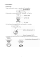
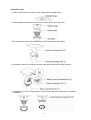
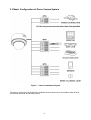
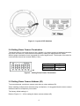
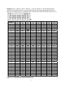
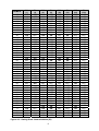
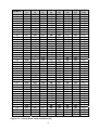
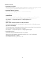
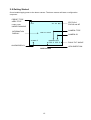
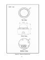
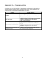
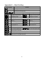
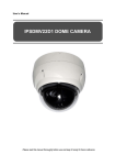
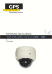
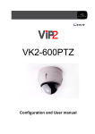
INSTRUCTION MANUAL
22X PTZ INDOOR DOME CAMERA
Model No.: RELPTZ22-1
(DC 12V
650mA)
REVO AMERICA
700 FREEPORT PARKWAY SUITE 100 COPPELL,
TX 75019 U.S.A TEL.: 1-866-625-REVO(7386)
Please read this manual thoroughly before use and keep it handy for future reference.
WARNING
TO REDUCE THE RISK OF FIRE OR ELECTRIC SHOCK, DO
NOT EXPOSE THIS PRODUCT TO RAIN OR MOISTURE. DO
NOT INSERT ANY METALLIC OBJECTS THROUGH THE
VENTILATION GRILLS OR OTHER OPENINGS ON THE
EQUIPMENT.
CAUTION
EXPLANATION OF GRAPHICAL SYMBOLS
The lightning flash with arrowhead symbol, within an
equilateral triangle, is intended to alert the user to
the presence of uninsulated “dangerous voltage”
within the product’s enclosure that may be of
sufficient magnitude to constitute a risk of electric
shock to persons.
The exclamation point within an equilateral is
intended to alert the user to the presence of
important operating and maintenance (servicing)
instructions in the literature accompanying the
appliance.
II
FCC COMPLIANCE STATEMENT
FCC INFORMATION: This equipment has been tested and found
to comply with the limits for a Class A digital device, pursuant to
Part 15 of the FCC Rules. These limits are designed to provide
reasonable protection against harmful interference when the
equipment is operated in a commercial environment. This
equipment generates, uses, and can radiate radio frequency energy
and, if not installed and used in accordance with the instruction
manual, may cause harmful interference to radio communications.
Operation of this equipment in a residential area is likely to cause
harmful interference in which case the user will be required to
correct the interference at his own expense.
CAUTION: Changes or modifications not expressly approved by
the party responsible for compliance could void the user’s authority
to operate the equipment.
This Class A digital apparatus complies with Canadian ICES-003.
Cet appareil numérique de la classe A est conforme à la norme
NMB-003 du Canada.
CE COMPLIANCE STATEMENT
WARNING
This is a Class A product. In a domestic environment this product
may cause radio interference in which case the user may be
required to take adequate measures.
III
IMPORTANT SAFETY INSTRUCTIONS
1.
2.
3.
4.
5.
6.
7.
Read these instructions.
Keep these instructions.
Heed all warnings.
Follow all instructions.
Do not use this apparatus near water.
Clean only with dry cloth.
Do not block any ventilation openings. Install in accordance with the
manufacturer’s instructions.
8. Do not install near any heat sources such as radiators, heat registers,
stoves, or other apparatus (including amplifiers) that produce heat.
9. Do not defeat the safety purpose of the polarized or grounding-type
plug. A polarized plug has two blades with one wider than the other. A
grounding type plug has two blades and a third grounding prong. The
wide blade or the third prong are provided for your safety. If the
provided plug does not fit into your outlet, consult an electrician for
replacement of the obsolete outlet.
10. Protect the power cord from being walked on or pinched particularly at
plugs, convenience receptacles, and the point where they exit from
the apparatus.
11. Only use attachments/accessories specified by the manufacturer.
12. Use only with the cart, stand, tripod, bracket, or table
specified by the manufacturer, or sold with the
apparatus. When a cart is used, use caution when
moving the cart/apparatus combination to avoid
injury from tip-over.
13. Unplug this apparatus during lightning storms or
when unused for long periods of time.
14. Refer all servicing to qualified service personnel. Servicing is required
when the apparatus has been damaged in any way, such as powersupply cord or plug is damaged, liquid has been moisture, does not
operate normally, or has been dropped.
15. CAUTION – THESE SERVICING INSTRUCTIONS ARE FOR USE
BY QUALIFIED SERVICE PERSONNEL ONLY. TO REDUCE THE
RISK OF ELECTRIC SHOCK DO NOT PERFORM ANY SERVICING
OTHER THAN THAT CONTAINED IN THE OPERATING
INSTRUCTIONS UNLESS YOU QRE QUALIFIED TO DO SO.
16. Use satisfy clause 2.5 of IEC60950-1/UL60950-1 or
Certified/Listed Class 2 power source only.
IV
Table of Contents
Chapter 1 — Introduction .......................................................................................................... 1
1.1 Features .............................................................................................................................................1
Chapter 2 — Installation and Configuration ......................................................................... 2
2.1 Package Contents ...........................................................................................................................2
2.2 Installation .........................................................................................................................................3
2.3 Basic Configuration of Dome Camera System ........................................................................5
2.4 Setting Dome Camera Termination .............................................................................................6
2.5 Setting Dome Camera Address (ID) ............................................................................................6
2.6 Setting Dome Camera Protocol .................................................................................................13
2.7 Connections ....................................................................................................................................14
2.8 Getting Started ...............................................................................................................................15
Chapter 3 — Program and Operation ................................................................................... 16
3.1 Dome Camera Selection ..............................................................................................................16
3.2 Accessing the On-Screen Menu Utility ....................................................................................16
3.3 How to control the On-Screen Menu Utility ............................................................................16
3.4 Auto Scan (Shortcut: SCAN) .....................................................................................................17
3.5 Preset (Shortcut: PRST) .............................................................................................................18
3.6 Shortcut of Preset Program ........................................................................................................20
3.7 Tour (Shortcut: TOUR) ................................................................................................................20
3.8 Alarm .................................................................................................................................................21
3.9 Area Title ..........................................................................................................................................21
3.10 Camera Menu................................................................................................................................22
3.11 Dome Setup ...................................................................................................................................25
Appendix A — Specifications ................................................................................................. 30
Appendix B — Troubleshooting ............................................................................................ 33
Appendix C — Short Cut Key ................................................................................................. 34
V
Chapter 1 — Introduction
1.1 Features
The dome camera and the keyboard controller make up the building blocks for any
surveillance/security system. Using multiple keyboard controllers and multiple dome cameras, no
place is too large for monitoring. Extensible and flexible architecture facilitates remote control
functions for a variety of external switching devices such as multiplexers and DVRs.
• Built-in optical power zoom camera with True Night Shot function
• 120 Preset positions
• 4 Tours consist of 42 Presets
• 4 Auto Scans and the Endless Auto-Pan with 13 speed steps
• 8 Area Titles
• 1 Alarm input / 1 Alarm output (5VTTL)
• Variable speed from 0.1°/sec to 240°/sec
Three Variable speed (SLOW, NORMAL, TURBO)
Turbo speed is 240°/sec with Ctrl key pressed.
• Pan / Tilt speed is inversely proportional to the zoom ratio with the option.
• Maximum speed is 240°/sec when Preset command.
• Auto Calibration from 0.1° to 6° (Tilt range is 0° to 90°)
• Programmable user preferences (alarm, preset, title, etc.)
• 90° Auto Flip
• Up to 255 selectable camera addresses
• Multi-language Menu Display, Password Confirmation
• Built-in RS-485 receiver driver
• 12VDC for Dome
• Use Certified/Listed Class 2 power source only.
1
Chapter 2 — Installation and Configuration
2.1 Package Contents
The dome camera is design to a compact, small size, flush/surface dome camera housing.
The housing is constructed of aluminum, steel and plastic. The housing is designed to be
mounted both wall and ceiling type.
* Dome Camera
* Instruction Manual (This Document)
* Template sheet
* Accessory kit
1) Plastic anchors
2) Screws (Tapping, 6x35)
3) O-Rings
4) Safety lanyard
5) Screw (Machine, NPC 2.6x6)
6) Screw (Machine, PC 2.6x6)
7) Screws (Machine, PC 4x8)
8) PT Plug
* Accessory connector
1) 2Pin Terminal Block
2) 4Pin Terminal Block + BNC Cable
3) 4Pin Terminal Block
2
1
1
1
1
(4)
(4)
(4)
(1)
(1)
(1)
(3)
(1)
1
(1)
(1)
(1)
2.2 Installation
(1) Flush Type
1) Make screw holes for camera on the ceiling with Template Sheet.
2) Disassemble a camera by Surface Case, Camera Set, and Top Case.
3) Fix the Camera Set using Anchors(3x) and Screws(3x) to the ceiling.
4) Assemble Top Case to Camera Set. Turn the Top case count clock wise to complete
installation.
3
(2) Surface Type
1) Make screw holes for camera on the ceiling with Template Sheet.
2) Disassemble a camera by Surface Case, Camera Set, and Top Case.
3) Fix the Surface Case using Anchors(4x) and Screws(4x) to the ceiling.
4) Assemble Camera Set into the Surface Case with Screws and Safety Lanyard.
5) Assemble Top Case to Camera Set. Turn the Top case count clock wise to complete
installation.
4
2.3 Basic Configuration of Dome Camera System
Figure 1 – Basic Installation Diagram
The dome camera must be installed by qualified service personnel in accordance with all local
and federal electrical and building codes.
5
Figure 2 – Layout of DIP Switches
2.4 Setting Dome Camera Termination
The device which is connected at end of line, whether it is a dome camera or keyboard controller,
must have the cable for communication terminated by setting the appropriate DIP switch.
Without proper termination, there is potential for control signal errors. Total length of the cable for
communication should not exceed 4000ft (1.2km).
S2
D1
Terminated
ON
Not terminated
OFF
S2
Figure 3 – Setting Dome Camera Termination
2.5 Setting Dome Camera Address (ID)
To prevent damage, each dome camera must have a unique address (ID).
When installing multiple dome cameras using a multiplexer, it is suggested that the dome camera
address match the multiplexer port number.
The factory default setting is 1.
Refer to Figure 4.1 ~ 4.6 for setting the dome camera address (ID).
6
Example: Port 1 = Dome 1, Port 2 = Dome 2 … Port 16 = Dome 16. If more than 16 dome
cameras are installed using two or more multiplexers, ID of the dome camera should be ID of
MUX x No. of camera IN. (e.g. multiplexer ID= n, Camera IN= m then ID of Dome =16x(n-1)+m )
S1
DOME ID
1
2
3
4
5
6
7
8
9
10
11
12
13
14
15
16
17
18
19
20
21
22
23
24
25
26
27
28
29
30
31
32
33
34
35
D1
(1)
ON
OFF
ON
OFF
ON
OFF
ON
OFF
ON
OFF
ON
OFF
ON
OFF
ON
OFF
ON
OFF
ON
OFF
ON
OFF
ON
OFF
ON
OFF
ON
OFF
ON
OFF
ON
OFF
ON
OFF
ON
D2
(2)
OFF
ON
ON
OFF
OFF
ON
ON
OFF
OFF
ON
ON
OFF
OFF
ON
ON
OFF
OFF
ON
ON
OFF
OFF
ON
ON
OFF
OFF
ON
ON
OFF
OFF
ON
ON
OFF
OFF
ON
ON
D3
(4)
OFF
OFF
OFF
ON
ON
ON
ON
OFF
OFF
OFF
OFF
ON
ON
ON
ON
OFF
OFF
OFF
OFF
ON
ON
ON
ON
OFF
OFF
OFF
OFF
ON
ON
ON
ON
OFF
OFF
OFF
OFF
D4
(8)
OFF
OFF
OFF
OFF
OFF
OFF
OFF
ON
ON
ON
ON
ON
ON
ON
ON
OFF
OFF
OFF
OFF
OFF
OFF
OFF
OFF
ON
ON
ON
ON
ON
ON
ON
ON
OFF
OFF
OFF
OFF
Figure 4.1 – Setting Dome Camera Address (ID)
7
D5
(16)
OFF
OFF
OFF
OFF
OFF
OFF
OFF
OFF
OFF
OFF
OFF
OFF
OFF
OFF
OFF
ON
ON
ON
ON
ON
ON
ON
ON
ON
ON
ON
ON
ON
ON
ON
ON
OFF
OFF
OFF
OFF
D6
(32)
OFF
OFF
OFF
OFF
OFF
OFF
OFF
OFF
OFF
OFF
OFF
OFF
OFF
OFF
OFF
OFF
OFF
OFF
OFF
OFF
OFF
OFF
OFF
OFF
OFF
OFF
OFF
OFF
OFF
OFF
OFF
ON
ON
ON
ON
D7
(64)
OFF
OFF
OFF
OFF
OFF
OFF
OFF
OFF
OFF
OFF
OFF
OFF
OFF
OFF
OFF
OFF
OFF
OFF
OFF
OFF
OFF
OFF
OFF
OFF
OFF
OFF
OFF
OFF
OFF
OFF
OFF
OFF
OFF
OFF
OFF
D8
(128)
OFF
OFF
OFF
OFF
OFF
OFF
OFF
OFF
OFF
OFF
OFF
OFF
OFF
OFF
OFF
OFF
OFF
OFF
OFF
OFF
OFF
OFF
OFF
OFF
OFF
OFF
OFF
OFF
OFF
OFF
OFF
OFF
OFF
OFF
OFF
DOME ID
36
37
38
39
40
41
42
43
44
45
46
47
48
49
50
51
52
53
54
55
56
57
58
59
60
61
62
63
64
65
66
67
68
69
70
71
72
73
74
75
76
77
78
79
80
D1
(1)
OFF
ON
OFF
ON
OFF
ON
OFF
ON
OFF
ON
OFF
ON
OFF
ON
OFF
ON
OFF
ON
OFF
ON
OFF
ON
OFF
ON
OFF
ON
OFF
ON
OFF
ON
OFF
ON
OFF
ON
OFF
ON
OFF
ON
OFF
ON
OFF
ON
OFF
ON
OFF
D2
(2)
OFF
OFF
ON
ON
OFF
OFF
ON
ON
OFF
OFF
ON
ON
OFF
OFF
ON
ON
OFF
OFF
ON
ON
OFF
OFF
ON
ON
OFF
OFF
ON
ON
OFF
OFF
ON
ON
OFF
OFF
ON
ON
OFF
OFF
ON
ON
OFF
OFF
ON
ON
OFF
D3
(4)
ON
ON
ON
ON
OFF
OFF
OFF
OFF
ON
ON
ON
ON
OFF
OFF
OFF
OFF
ON
ON
ON
ON
OFF
OFF
OFF
OFF
ON
ON
ON
ON
OFF
OFF
OFF
OFF
ON
ON
ON
ON
OFF
OFF
OFF
OFF
ON
ON
ON
ON
OFF
D4
(8)
OFF
OFF
OFF
OFF
ON
ON
ON
ON
ON
ON
ON
ON
OFF
OFF
OFF
OFF
OFF
OFF
OFF
OFF
ON
ON
ON
ON
ON
ON
ON
ON
OFF
OFF
OFF
OFF
OFF
OFF
OFF
OFF
ON
ON
ON
ON
ON
ON
ON
ON
OFF
Figure 4.2 – Setting Dome Camera Address (ID)
8
D5
(16)
OFF
OFF
OFF
OFF
OFF
OFF
OFF
OFF
OFF
OFF
OFF
OFF
ON
ON
ON
ON
ON
ON
ON
ON
ON
ON
ON
ON
ON
ON
ON
ON
OFF
OFF
OFF
OFF
OFF
OFF
OFF
OFF
OFF
OFF
OFF
OFF
OFF
OFF
OFF
OFF
ON
D6
(32)
ON
ON
ON
ON
ON
ON
ON
ON
ON
ON
ON
ON
ON
ON
ON
ON
ON
ON
ON
ON
ON
ON
ON
ON
ON
ON
ON
ON
OFF
OFF
OFF
OFF
OFF
OFF
OFF
OFF
OFF
OFF
OFF
OFF
OFF
OFF
OFF
OFF
OFF
D7
(64)
OFF
OFF
OFF
OFF
OFF
OFF
OFF
OFF
OFF
OFF
OFF
OFF
OFF
OFF
OFF
OFF
OFF
OFF
OFF
OFF
OFF
OFF
OFF
OFF
OFF
OFF
OFF
OFF
ON
ON
ON
ON
ON
ON
ON
ON
ON
ON
ON
ON
ON
ON
ON
ON
ON
D8
(128)
OFF
OFF
OFF
OFF
OFF
OFF
OFF
OFF
OFF
OFF
OFF
OFF
OFF
OFF
OFF
OFF
OFF
OFF
OFF
OFF
OFF
OFF
OFF
OFF
OFF
OFF
OFF
OFF
OFF
OFF
OFF
OFF
OFF
OFF
OFF
OFF
OFF
OFF
OFF
OFF
OFF
OFF
OFF
OFF
OFF
DOME ID
81
82
83
84
85
86
87
88
89
90
91
92
93
94
95
96
97
98
99
100
101
102
103
104
105
106
107
108
109
110
111
112
113
114
115
116
117
118
119
120
121
122
123
124
125
D1
(1)
ON
OFF
ON
OFF
ON
OFF
ON
OFF
ON
OFF
ON
OFF
ON
OFF
ON
OFF
ON
OFF
ON
OFF
ON
OFF
ON
OFF
ON
OFF
ON
OFF
ON
OFF
ON
OFF
ON
OFF
ON
OFF
ON
OFF
ON
OFF
ON
OFF
ON
OFF
ON
D2
(2)
OFF
ON
ON
OFF
OFF
ON
ON
OFF
OFF
ON
ON
OFF
OFF
ON
ON
OFF
OFF
ON
ON
OFF
OFF
ON
ON
OFF
OFF
ON
ON
OFF
OFF
ON
ON
OFF
OFF
ON
ON
OFF
OFF
ON
ON
OFF
OFF
ON
ON
OFF
OFF
D3
(4)
OFF
OFF
OFF
ON
ON
ON
ON
OFF
OFF
OFF
OFF
ON
ON
ON
ON
OFF
OFF
OFF
OFF
ON
ON
ON
ON
OFF
OFF
OFF
OFF
ON
ON
ON
ON
OFF
OFF
OFF
OFF
ON
ON
ON
ON
OFF
OFF
OFF
OFF
ON
ON
D4
(8)
OFF
OFF
OFF
OFF
OFF
OFF
OFF
ON
ON
ON
ON
ON
ON
ON
ON
OFF
OFF
OFF
OFF
OFF
OFF
OFF
OFF
ON
ON
ON
ON
ON
ON
ON
ON
OFF
OFF
OFF
OFF
OFF
OFF
OFF
OFF
ON
ON
ON
ON
ON
ON
Figure 4.3 – Setting Dome Camera Address (ID)
9
D5
(16)
ON
ON
ON
ON
ON
ON
ON
ON
ON
ON
ON
ON
ON
ON
ON
OFF
OFF
OFF
OFF
OFF
OFF
OFF
OFF
OFF
OFF
OFF
OFF
OFF
OFF
OFF
OFF
ON
ON
ON
ON
ON
ON
ON
ON
ON
ON
ON
ON
ON
ON
D6
(32)
OFF
OFF
OFF
OFF
OFF
OFF
OFF
OFF
OFF
OFF
OFF
OFF
OFF
OFF
OFF
ON
ON
ON
ON
ON
ON
ON
ON
ON
ON
ON
ON
ON
ON
ON
ON
ON
ON
ON
ON
ON
ON
ON
ON
ON
ON
ON
ON
ON
ON
D7
(64)
ON
ON
ON
ON
ON
ON
ON
ON
ON
ON
ON
ON
ON
ON
ON
ON
ON
ON
ON
ON
ON
ON
ON
ON
ON
ON
ON
ON
ON
ON
ON
ON
ON
ON
ON
ON
ON
ON
ON
ON
ON
ON
ON
ON
ON
D8
(128)
OFF
OFF
OFF
OFF
OFF
OFF
OFF
OFF
OFF
OFF
OFF
OFF
OFF
OFF
OFF
OFF
OFF
OFF
OFF
OFF
OFF
OFF
OFF
OFF
OFF
OFF
OFF
OFF
OFF
OFF
OFF
OFF
OFF
OFF
OFF
OFF
OFF
OFF
OFF
OFF
OFF
OFF
OFF
OFF
OFF
DOME ID
126
127
128
129
130
131
132
133
134
135
136
137
138
139
140
141
142
143
144
145
146
147
148
149
150
151
152
153
154
155
156
157
158
159
160
161
162
163
164
165
166
167
168
169
170
D1
(1)
OFF
ON
OFF
ON
OFF
ON
OFF
ON
OFF
ON
OFF
ON
OFF
ON
OFF
ON
OFF
ON
OFF
ON
OFF
ON
OFF
ON
OFF
ON
OFF
ON
OFF
ON
OFF
ON
OFF
ON
OFF
ON
OFF
ON
OFF
ON
OFF
ON
OFF
ON
OFF
D2
(2)
ON
ON
OFF
OFF
ON
ON
OFF
OFF
ON
ON
OFF
OFF
ON
ON
OFF
OFF
ON
ON
OFF
OFF
ON
ON
OFF
OFF
ON
ON
OFF
OFF
ON
ON
OFF
OFF
ON
ON
OFF
OFF
ON
ON
OFF
OFF
ON
ON
OFF
OFF
ON
D3
(4)
ON
ON
OFF
OFF
OFF
OFF
ON
ON
ON
ON
OFF
OFF
OFF
OFF
ON
ON
ON
ON
OFF
OFF
OFF
OFF
ON
ON
ON
ON
OFF
OFF
OFF
OFF
ON
ON
ON
ON
OFF
OFF
OFF
OFF
ON
ON
ON
ON
OFF
OFF
OFF
D4
(8)
ON
ON
OFF
OFF
OFF
OFF
OFF
OFF
OFF
OFF
ON
ON
ON
ON
ON
ON
ON
ON
OFF
OFF
OFF
OFF
OFF
OFF
OFF
OFF
ON
ON
ON
ON
ON
ON
ON
ON
OFF
OFF
OFF
OFF
OFF
OFF
OFF
OFF
ON
ON
ON
Figure 4.4 – Setting Dome Camera Address (ID)
10
D5
(16)
ON
ON
OFF
OFF
OFF
OFF
OFF
OFF
OFF
OFF
OFF
OFF
OFF
OFF
OFF
OFF
OFF
OFF
ON
ON
ON
ON
ON
ON
ON
ON
ON
ON
ON
ON
ON
ON
ON
ON
OFF
OFF
OFF
OFF
OFF
OFF
OFF
OFF
OFF
OFF
OFF
D6
(32)
ON
ON
OFF
OFF
OFF
OFF
OFF
OFF
OFF
OFF
OFF
OFF
OFF
OFF
OFF
OFF
OFF
OFF
OFF
OFF
OFF
OFF
OFF
OFF
OFF
OFF
OFF
OFF
OFF
OFF
OFF
OFF
OFF
OFF
ON
ON
ON
ON
ON
ON
ON
ON
ON
ON
ON
D7
(64)
ON
ON
OFF
OFF
OFF
OFF
OFF
OFF
OFF
OFF
OFF
OFF
OFF
OFF
OFF
OFF
OFF
OFF
OFF
OFF
OFF
OFF
OFF
OFF
OFF
OFF
OFF
OFF
OFF
OFF
OFF
OFF
OFF
OFF
OFF
OFF
OFF
OFF
OFF
OFF
OFF
OFF
OFF
OFF
OFF
D8
(128)
OFF
OFF
ON
ON
ON
ON
ON
ON
ON
ON
ON
ON
ON
ON
ON
ON
ON
ON
ON
ON
ON
ON
ON
ON
ON
ON
ON
ON
ON
ON
ON
ON
ON
ON
ON
ON
ON
ON
ON
ON
ON
ON
ON
ON
ON
DOME ID
171
172
173
174
175
176
177
178
179
180
181
182
183
184
185
186
187
188
189
190
191
192
193
194
195
196
197
198
199
200
201
202
203
204
205
206
207
208
209
210
211
212
213
214
215
D1
(1)
ON
OFF
ON
OFF
ON
OFF
ON
OFF
ON
OFF
ON
OFF
ON
OFF
ON
OFF
ON
OFF
ON
OFF
ON
OFF
ON
OFF
ON
OFF
ON
OFF
ON
OFF
ON
OFF
ON
OFF
ON
OFF
ON
OFF
ON
OFF
ON
OFF
ON
OFF
ON
D2
(2)
ON
OFF
OFF
ON
ON
OFF
OFF
ON
ON
OFF
OFF
ON
ON
OFF
OFF
ON
ON
OFF
OFF
ON
ON
OFF
OFF
ON
ON
OFF
OFF
ON
ON
OFF
OFF
ON
ON
OFF
OFF
ON
ON
OFF
OFF
ON
ON
OFF
OFF
ON
ON
D3
(4)
OFF
ON
ON
ON
ON
OFF
OFF
OFF
OFF
ON
ON
ON
ON
OFF
OFF
OFF
OFF
ON
ON
ON
ON
OFF
OFF
OFF
OFF
ON
ON
ON
ON
OFF
OFF
OFF
OFF
ON
ON
ON
ON
OFF
OFF
OFF
OFF
ON
ON
ON
ON
D4
(8)
ON
ON
ON
ON
ON
OFF
OFF
OFF
OFF
OFF
OFF
OFF
OFF
ON
ON
ON
ON
ON
ON
ON
ON
OFF
OFF
OFF
OFF
OFF
OFF
OFF
OFF
ON
ON
ON
ON
ON
ON
ON
ON
OFF
OFF
OFF
OFF
OFF
OFF
OFF
OFF
Figure 4.5 – Setting Dome Camera Address (ID)
11
D5
(16)
OFF
OFF
OFF
OFF
OFF
ON
ON
ON
ON
ON
ON
ON
ON
ON
ON
ON
ON
ON
ON
ON
ON
OFF
OFF
OFF
OFF
OFF
OFF
OFF
OFF
OFF
OFF
OFF
OFF
OFF
OFF
OFF
OFF
ON
ON
ON
ON
ON
ON
ON
ON
D6
(32)
ON
ON
ON
ON
ON
ON
ON
ON
ON
ON
ON
ON
ON
ON
ON
ON
ON
ON
ON
ON
ON
OFF
OFF
OFF
OFF
OFF
OFF
OFF
OFF
OFF
OFF
OFF
OFF
OFF
OFF
OFF
OFF
OFF
OFF
OFF
OFF
OFF
OFF
OFF
OFF
D7
(64)
OFF
OFF
OFF
OFF
OFF
OFF
OFF
OFF
OFF
OFF
OFF
OFF
OFF
OFF
OFF
OFF
OFF
OFF
OFF
OFF
OFF
ON
ON
ON
ON
ON
ON
ON
ON
ON
ON
ON
ON
ON
ON
ON
ON
ON
ON
ON
ON
ON
ON
ON
ON
D8
(128)
ON
ON
ON
ON
ON
ON
ON
ON
ON
ON
ON
ON
ON
ON
ON
ON
ON
ON
ON
ON
ON
ON
ON
ON
ON
ON
ON
ON
ON
ON
ON
ON
ON
ON
ON
ON
ON
ON
ON
ON
ON
ON
ON
ON
ON
DOME ID
216
217
218
219
220
221
222
223
224
225
226
227
228
229
230
231
232
233
234
235
236
237
238
239
240
241
242
243
244
245
246
247
248
249
250
251
252
253
254
255
D1
(1)
OFF
ON
OFF
ON
OFF
ON
OFF
ON
OFF
ON
OFF
ON
OFF
ON
OFF
ON
OFF
ON
OFF
ON
OFF
ON
OFF
ON
OFF
ON
OFF
ON
OFF
ON
OFF
ON
OFF
ON
OFF
ON
OFF
ON
OFF
ON
D2
(2)
OFF
OFF
ON
ON
OFF
OFF
ON
ON
OFF
OFF
ON
ON
OFF
OFF
ON
ON
OFF
OFF
ON
ON
OFF
OFF
ON
ON
OFF
OFF
ON
ON
OFF
OFF
ON
ON
OFF
OFF
ON
ON
OFF
OFF
ON
ON
D3
(4)
OFF
OFF
OFF
OFF
ON
ON
ON
ON
OFF
OFF
OFF
OFF
ON
ON
ON
ON
OFF
OFF
OFF
OFF
ON
ON
ON
ON
OFF
OFF
OFF
OFF
ON
ON
ON
ON
OFF
OFF
OFF
OFF
ON
ON
ON
ON
D4
(8)
ON
ON
ON
ON
ON
ON
ON
ON
OFF
OFF
OFF
OFF
OFF
OFF
OFF
OFF
ON
ON
ON
ON
ON
ON
ON
ON
OFF
OFF
OFF
OFF
OFF
OFF
OFF
OFF
ON
ON
ON
ON
ON
ON
ON
ON
Figure 4.6 – Setting Dome Camera Address (ID)
12
D5
(16)
ON
ON
ON
ON
ON
ON
ON
ON
OFF
OFF
OFF
OFF
OFF
OFF
OFF
OFF
OFF
OFF
OFF
OFF
OFF
OFF
OFF
OFF
ON
ON
ON
ON
ON
ON
ON
ON
ON
ON
ON
ON
ON
ON
ON
ON
D6
(32)
OFF
OFF
OFF
OFF
OFF
OFF
OFF
OFF
ON
ON
ON
ON
ON
ON
ON
ON
ON
ON
ON
ON
ON
ON
ON
ON
ON
ON
ON
ON
ON
ON
ON
ON
ON
ON
ON
ON
ON
ON
ON
ON
D7
(64)
ON
ON
ON
ON
ON
ON
ON
ON
ON
ON
ON
ON
ON
ON
ON
ON
ON
ON
ON
ON
ON
ON
ON
ON
ON
ON
ON
ON
ON
ON
ON
ON
ON
ON
ON
ON
ON
ON
ON
ON
D8
(128)
ON
ON
ON
ON
ON
ON
ON
ON
ON
ON
ON
ON
ON
ON
ON
ON
ON
ON
ON
ON
ON
ON
ON
ON
ON
ON
ON
ON
ON
ON
ON
ON
ON
ON
ON
ON
ON
ON
ON
ON
2.6 Setting Dome Camera Protocol
If a dome camera is to be installed with the keyboard controller, select the default protocol.
Consult service personnel if a dome camera is installed with device other than a keyboard
controller.
S2
You can set Protocol with dip switch D2, D3 and D4 in S2.
S2
PROTOCOL
D2
D3
D4
OFF
OFF
OFF
F2, REVO TRAX, Pelco-P, Pelco-D : default
OFF
OFF
ON
F2, REVO TRAX
OFF
ON
ON
Pelco-P, Pelco-D
You can set Baud Rate with dip switch D5 and D6 in S2.
S2
BAUD RATE
D5
D6
OFF
OFF
2400 bps
OFF
ON
4800 bps
ON
OFF
9600 bps : default
ON
ON
19200 bps
Figure 5 – Protocol, Baud rate Selection Switches
13
2.7 Connections
• Connecting to the RS485
The dome camera can be controlled remotely by an external device or control system, such as
a control keyboard, using RS485 half-duplex serial communications signals.
• Connecting Video out connector
Connect the video out (BNC) connector to the monitor or video input.
• Connecting Alarms
AI (Alarm Input)
You can use external devices to signal the dome camera to react on events. Mechanical or
electrical switches can be wired to the AI (Alarm Input) and G (Ground) connectors.
See Chapter 3 — Program and Operation for configuring alarm input.
G (Ground)
NOTE: All the connectors marked G or GND are common.
Connect the ground side of the alarm input and/or alarm output to the G (Ground) connector.
AO (5VTTL Alarm Output)
The dome camera can activate external devices such as buzzers or lights. Connect the device
to the AO (Alarm Output) and G (Ground) connectors.
See Chapter 3 — Program and Operation for configuring alarm output.
• Connecting the Power
Connect the power of 12VDC 650mA for the dome camera.
When using a 12VDC adapter, connector the positive(+) pole to the ‘+’ position and
the negative(-) pole to the ‘-’ position.
Use Certified/Listed Class 2 power source only.
14
2.8 Getting Started
Once installed apply power to the dome camera. The dome camera will start a configuration
sequence.
PRESET TITLE
AREA TITLE
FUNCTION
UNDER RUNNING
001
AF AE
STATUS of
FOCUS and AE
CAMERA TITLE
INFORMATION
DISPLAY
EMPTY DATA
CAMERA ID
ALARM:1
DOMEID:001
W→360.0 090.0
ALARM DISPLAY
PAN & TILT ANGLE
VIEW DIRECTION
OSD Position
15
Chapter 3 — Program and Operation
3.1 Dome Camera Selection
Before you program or operate a dome camera, you must select the dome camera by pressing
No. + CAM keys.
Example: Pressing 1 , 0 + CAM keys sequentially will select dome camera 10. The selected
dome camera ID will be displayed on the LCD monitor of the keyboard controller.
3.2 Accessing the On-Screen Menu Utility
You can call up the On-screen menu utility on your monitor by pressing the MENU key on the
keyboard controller, the following On-screen menu utility will appear:
DOME MENU
AUTO SCAN
PRESET
TOUR
ALARM
AREA TITLE
CAMERA
DOME SETUP
EXIT(ESC TO EXIT)
3.3 How to control the On-Screen Menu Utility
Function
Button
Call the On-screen menu utility.
MENU
Navigate through the menu items.
Joystick up or down
Go into the sub-menu items.
Joystick right or IRIS Open
Change value.
Enter the editing title mode.
Joystick left or right or
Zoom handle twist or Tele , Wide
Change value of angle.
CTRL + Joystick
Enter the changing angle mode.
IRIS Open
Exit the changing angle mode.
IRIS Close
Escape (EXIT)
ESC or Joystick left
16
3.4 Auto Scan
(Shortcut: SCAN)
The Auto Scan supports up to 5 programmed angles at user-programmable speeds. Follow
these steps to program Auto Scan:
AUTO SCAN SETUP
NUMBER
: 01
TITLE
: A01
SPEED
: 05 STEP
START ANGLE
: ----- ----END ANGLE
: ----- ----SCAN DIR
: CCW
SWAP
: OFF
DWELL
: 03 SEC
SAVE AND EXIT(ESC TO CANCEL)
NUMBER
TITLE
SPEED
SCAN DIR
SWAP
DWELL
: 01 ~ 04, 09:AUTO PAN mode.
: up to 12 characters.
: 01 ~ 13 step, the lower number means the slower speed.
: Set the Scan direction, CCW(Counter Clock Wise), CW(Clock Wise).
: Swap the start point for the end point.
: Set the dwell time at the both end, 01 ~ 99 seconds.
1. Press the MENU key to display the main menu on the monitor. Scroll to Auto Scan and push
the Joystick to the right.
2. Select “NUMBER” and set the desired number by pushing the Joystick to the left or right.
3. Select “TITLE” and twist the Joystick to enter the title edit mode.
4. Twist the Joystick by changing the alphanumeric characters and move the next position.
Or move down to the character table and press the CTRL or IRIS Open key at the desired
character then the cursor position moves to the next position automatically. Push the Joystick
to the left or right at the “ALL DELETE” field to delete all characters. Push the Joystick to the
left or right at the “EXIT” field to finish title edit menu.
TITLE EDIT MENU
A01
*
A B C D E F G H I J
K L M N O P Q R S T
U V W X Y Z 0 1 2 3
4 5 6 7 8 9 ( )
ALL DELETE
EXIT(ESC TO EXIT)
5. Select “START ANGLE”. Hold down the CTRL key while selecting the start position using the
Joystick. Current panning position will be displayed. Release the CTRL key to complete the
selection of the start position. Or press the IRIS Open key then the “CTRL” displays. Move the
desired position and the zoom position. Press the IRIS Close key then the “CTRL” disappears.
17
6. Select “END ANGLE”. Hold down the CTRL key while moving the Joystick to select the end
position. The end position angle should be larger than start position. Release the CTRL key to
complete the selection of the end position. Or press the IRIS Open key then the “CTRL”
displays. Move the desired position and the zoom position. Press the IRIS Close key then the
“CTRL” disappears.
7. Set “SCAN DIR” to CCW or CW.
8. Select “SWAP”, Set to ON, to exchange the start angle and the end angle.
9. Set “DWELL TIME”.
10. Select “SAVE AND EXIT” and push the Joystick to the right or press the IRIS Open key.
Press the ESC or IRIS Close key to exit the program without saving.
NOTE: Pressing the HOME key delete stored data at the angle field.
NOTE: 09:AUTO-PAN mode (Endless panning)
3.5 Preset
(Shortcut: PRST)
If you need to view specific places routinely, you should program Presets. A Preset is a
programmed video scene with automatic pan, tilt, zoom, focus and motion settings. Once
programmed, placing the number position and pressing the PRST key on your controller calls up
that Preset automatically. In addition, Presets may be assigned to alarm action or as the “home”
position for the dome camera. As many as 120 Presets, whose positions are saved in the dome’s
firmware, may be programmed.
There are two pages of Preset menu. Each page has 60 Presets. Pages can be scrolled by
pushing the Joystick to the left or right on the first or last No. of Preset.
PRESET SETUP
NUMBER
: 001
TITLE
: --CAMERA SET
DWELL
: -- SEC
12345678901234567890
00 █**----------------02 -------------------04 -------------------NEXT PAGE
SAVE AND EXIT(ESC TO CANCEL)
- : blank Preset position
* : position has the Preset
█ : current cursor position
Follow steps below to store the Preset positions:
1. Press the MENU key to display the main menu on the monitor. Scroll to Preset and push the
Joystick to the right.
2. Select the blank Preset position to be stored by pushing the Joystick up, down, right, or left.
18
3. After selecting a blank position, press and hold the CTRL key. Use the Joystick to control the
direction of the camera and lens.
4. After aiming the camera (view direction and lens control), release the CTRL key. The cursor
will be on the “TITLE” after saving data then twist the Joystick or press the Tele or Wide key
to edit the Preset title. Follow the procedure of the Auto Scan above to edit titles.
5. Select “CAMERA SET” and pushing the Joystick to the left or right. Then the Preset camera
setup displays.
PRESET CAMERA SETUP
FOCUS
: AUTO
MOTION
: OFF
MOTION SETUP
SAVE AND EXIT(ESC TO CANCEL)
Set FOCUS
Set MOTION
: AUTO, MANUAL, ONE PUSH
: OFF, ON
Select “MOTION SETUP” and pushing the Joystick to the left or right. Then the MOTION
setup displays.
MOTION SETUP
SENSITIVITY
: 06
POSITION
: ALL
DELAY
: 00 SEC
OUTPUT
: OFF
HOLD TIME
: 03 SEC
EXIT(ESC TO EXIT)
Set SENSITIVITY
Set POSITION
Set DELAY
Set OUTPUT
Set HOLD TIME
: 01 ~ 10
: ALL, CENTER
: 00 ~ 05 SEC
: OFF, ON
: 03 ~ 99 SEC
6. Set “DWELL TIME”. (03 ~ 99 seconds)
7. To select the next page of Presets, scroll the page by pushing the Joystick to the left on the
first and last columns of the menu.
8. Repeat step 2 through 7 for each additional Preset position.
9. Select “SAVE AND EXIT” and push the Joystick to the right or press the IRIS Open key.
Press the ESC or IRIS Close key to exit the program without saving.
NOTE: Press the HOME key at programmed Preset position(*) to delete a programmed
Preset view.
The position, which is marked with the *, already has the Preset view assigned. To review the
stored Preset, twist the Joystick on the *.
19
3.6 Shortcut of Preset Program
After selecting the desired scene, press No. (1 to 120), and press the CTRL and PRST keys
subsequently. The current view will be stored to the selected Preset number if the Preset number
is empty. If selected Preset number is not empty, “OVER WRITE” message will be displayed on
the monitor and select the “OK” and push the Joystick to the right to overwrite.
Example: 1 , 0 , 1 + CTRL + PRST keys will store current view as Preset no. 101. In this case,
focus will be programmed as Auto, dwell time will be set to 3 second, and the current
AE mode will be programmed.
3.7 Tour
(Shortcut: TOUR)
There are 4 programmable Tours. Each Tour consists of up to 42 Preset positions.
TOUR SETUP
NUMBER
: 01
TITLE
: T01
SPEED
: 05 STEP
DWELL
: -- SEC
001 002 --- --- --- --- ----- --- --- --- --- --- ----- --- 003 --- --- --- ----- 004 --- --- --- --- ----- --- --- --- --- --- ----- --- --- --- --- --- --SAVE AND EXIT(ESC TO CANCEL)
--DWELL
001
: blank position
: 03 ~ 99 SEC
: Preset (1 ~ 120)
Follow the steps below to program the Tours:
1. Press the MENU key to display the main menu on the monitor. Scroll to Tour and push the
Joystick to the right to enter the Tour menu.
2. Select “NUMBER” and set the desired number by pushing the Joystick to the left or right.
3. Choose a blank position to be programmed by pushing the Joystick up, down, right, or left.
4. To add a stored Preset, twist the Joystick then the stored Preset number displays.
5. You can also overwrite the programmed number and to remove a stored number from the
Tour, press the HOME key on the stored number, a blank position mark (---) will be displayed.
6. Repeat step 2 through 5 for each desired position. Each title will be displayed on top of the line.
7. To edit the “TITLE”, follow the procedure of the Auto Scan above to edit titles.
8. Select “SAVE AND EXIT” and push the Joystick to the right or press the IRIS Open key.
Press the ESC or IRIS Close key to exit the program without saving.
20
3.8 Alarm
ALARM SETUP
NO
01
PRI FUN IN
1 001 NC
OUT
ON
HLD LATCH
03
OFF
SAVE AND EXIT(ESC TO CANCEL)
NO
PRI(Priority)
FUN(Function)
IN
OUT
HLD(Hold)
LATCH
: alarm input number
: The lower number has higher priority. (1 fixed)
: Stored preset number to be called by alarm.
: NO/NC – normally open/closed, OFF – ignore
: ON – 5VTTL output on, OFF – No output
: Alarm will be held for programmed time. (03 to 99 seconds)
: ON – Alarm message will remain on the screen even though alarm input
is deactivated.
OFF – Alarm message will disappear on the screen after programmed
hold time when alarm input is deactivated.
3.9 Area Title
Enter a specific name on programmed angle between START and END. For the screen below,
when the camera points at an angle between 124.3° (PAN), 30.7° (TILT) to 359.5° (PAN), 45.4°
(TILT), ABC will be displayed on the screen.
AREA TITLE SETUP
NUMBER
: 01
TITLE
: ABC
START ANGLE
: 124.3 30.7
END ANGLE
: 359.5 45.4
SWAP
: OFF
SAVE AND EXIT(ESC TO CANCEL)
NUMBER
TITLE
SWAP
: 01 ~ 08
: up to 12 characters.
: Swap the start point for the end point.
1. Select “NUMBER” and set the desired number by pushing the Joystick to the left or right.
2. To edit the “TITLE”, follow the procedure of the Auto Scan above to edit titles.
3. Select “START ANGLE”. Hold down the CTRL key while selecting the start position using the
Joystick. Current panning position will be displayed. Release the CTRL key to complete the
selection of the start position. Or press the IRIS Open key then the “CTRL” displays. Move the
desired position. Press the IRIS Close key then the “CTRL” disappears.
4. Select “END ANGLE”. Hold down the CTRL key while moving the Joystick to select the end
position. Release the CTRL key to complete the selection of the end position. Or press the
21
IRIS Open key then the “CTRL” displays. Move the desired position. Press the IRIS Close key
then the “CTRL” disappears.
5. Select “SWAP”. Set to ON, to exchange the start angle and the end angle.
6. Select “SAVE AND EXIT” and push the Joystick to the right or press the IRIS Open key.
Press the ESC or IRIS Close key to exit the program without saving.
3.10 Camera Menu
CAMERA SETUP
FOCUS CONTROL
WB CONTROL
AE CONTROL
SHARPNESS
: 05
RESOLUTION
: LOW
SAVE AND EXIT(ESC TO CANCEL)
SHARPNESS
RESOLUTION
The higher the value, the more edges in the picture will be
enhanced. (0 ~ 15)
Select high resolution mode. (LOW / MID / HIGH)
• FOCUS CONTROL
FOCUS SETUP
MODE
: AUTO
FOCUS LIMIT
: 1.0M
SAVE AND EXIT(ESC TO CANCEL)
MODE
FOCUS LIMIT
AUTO / MANUAL / ONE PUSH / CONSTANT MANUAL
Use manual mode in normal use.
This distance is approximate value and the focus operate from the setting
value.
CAUTION: Avoid continuous, 24-hour use of the auto focus. This will shorten the
lifespan of the lens.
• WB (White Balance) CONTROL
WB SETUP
MODE
: AWB
R GAIN
: --B GAIN
: --SAVE AND EXIT(ESC TO CANCEL)
MODE
AWB
AWB / WAWB / INDOOR / OUTDOOR / MANUAL
Computes the white balance value output using color information
from the entire screen automatically. (2500 to 9500 °K)
22
WAWB
INDOOR
OUTDOOR
MANUAL
RGAIN
BGAIN
Wide range auto white balance mode (1800 to 10500 °K)
Indoor white balance mode
Outdoor white balance mode
Manual mode, you can change R and B Gain manually.
0 ~ 255
0 ~ 255
RGAIN / BGAIN modes are controllable only in MANUAL Mode.
• AE CONTROL
AE SETUP
MODE
GAIN
BRIGHT
SHUTTER
FLICKERLESS
BACK LIGHT
ATR
DNR
NIGHT SHOT
SAVE AND EXIT(ESC
MODE
AE1
AE2
SHUTTER PRIO
MANUAL
GAIN
BRIGHT
SHUTTER
FLICKERLESS
BACK LIGHT
ATR
DNR
NIGHT SHOT
: MANUAL
: MIN
: 024
: 1/50
: --: OFF
: --: --: AUTO
TO CANCEL)
AE1 / AE2 / SHUTTER PRIO / MANUAL
Auto exposure mode1 (Use to normal surroundings: indoor)
Auto exposure mode2 (Use to high brightness surroundings: outdoor)
Variable Shutter speed, Auto Gain
Variable Shutter speed, Gain
MIN / LOW / MID / HIGH
10 ~ 50
1/60(50), 1/100(120), 1/250, 1/500, 1/1000, 1/2000, 1/4000, 1/10000
OFF / ON
OFF / BLC / HLC
OFF / ON
OFF / 1 ~ 7
AUTO / ON / OFF / GLOBAL
NOTE: Values in ( ) are for PAL Camera.
NOTE: When BACKLIGHT set BLC or HLC, focus issues may occur in certain lighting
conditions.
The NIGHT SHOT option removes the IR cutoff filter of the camera and makes the camera
sensitive to near infrared.
AUTO
GLOBAL
Camera goes in to B&W mode at low light.
Controlled by the keyboard
(NOTE: GLOBAL function operates F2E protocol only)
The operator can enable NIGHT SHOT for all dome cameras at the same time.
If the NIGHT SHOT mode is set to GLOBAL, “999” + ENTER will turn Off the NIGHT
SHOT mode and “888” + ENTER will turn On the NIGHT SHOT mode.
ON
B/W mode
OFF
Color mode
NOTE: AUTO in NIGHT SHOT function is not applied in “MANUAL” mode of AE Control.
23
24
3.11 Dome Setup
CONFIGURATION MENU
LANGUAGE
: ENGLISH
HOME FUNCTION SETUP
OSD DISPLAY
VIEW ANGLE SETUP
INITIALIZE DATA
SYSTEM MENU
SYSTEM INFORMATION
SAVE AND EXIT(ESC TO CANCEL)
• LANGUAGE SETUP
LANGUAGE
: Select the language you want.
• HOME FUNCTION SETUP
HOME FUNCTION SETUP
HOME FUNCTION
FUNCTION NUMBER
WAITING TIME
FUNCTION ENABLE
SAVE AND EXIT(ESC
HOME FUNCTION
FUNCTION NUMBER
WAITING TIME
FUNCTION ENABLE
: NONE
: --: 120 SEC
: OFF
TO CANCEL)
: None / Tour / Auto Scan / Preset
:--: 10 ~ 240 seconds
: ON / OFF
The Home function can be set so that the camera automatically goes to Tour, Auto Scan or
Preset after the keyboard controller has been idle for a amount of time.
For example, if the controller is idle for 120 seconds, the camera goes to Preset 1.
Follow these steps to program the Home position:
1. Select “HOME FUNCTION” by pushing the Joystick to the left or right to scroll through the
None, Tour, Auto Scan or Preset functions.
2. Select “FUNCTION NUMBER” and push the Joystick to the left or right. The recorded
function number will scroll.
3. Select “WAITING TIME” and push the Joystick to the left or right to select from 10 to 240
seconds.
4. Select “FUNCTION ENABLE” and turn to ON or OFF by pushing the Joystick to the left or
right.
25
• OSD DISPLAY
OSD DISPLAY SETUP
CAMERA TITLE
VIEW DIRECTION
DOME OSD
AREA TITLE
PRESET TITLE
FOCUS EXPOSURE
:
:
:
:
:
:
DOMEID
OFF
ON
OFF
CONSTANT
ON
SAVE AND EXIT(ESC TO CANCEL)
CAMERA TITLE
: up to 6 characters.
VIEW DIRECTION
: ON / OFF
“ON” sets 0 degree is N(North). “OFF” hides the directional title. Every 90 degrees of
clockwise rotation will change the title to E(East), S(South), W(West).
DOME OSD
: ON / OFF
All display or title will disappear when DOME OSD DISPLAY sets OFF.
AREA TITLE
: ON / OFF
If this option is enabled, the area title displays when the camera moves.
NOTE: The DOME OSD DISPLAY must be enabled.
PRESET TITLE
: CONSTANT / OFF
Set the Preset title display.
FOCUS EXPOSURE
: ON / OFF
ON: FOCUS and EXPOSURE displays. (AF AE)
• VIEW ANGLE SETUP
VIEW ANGLE SETUP
FLIP
: AUTO
TILT LIMIT
: OFF
SAVE AND EXIT(ESC TO CANCEL)
FLIP: OFF, AUTO
OFF: the dome camera moves until 90° vertically.
AUTO: When the camera reaches the floor directly above the moving object, it will stop. At
that time, release the Joystick instantly and pull it down again to run the auto-flip function.
When you use the panning range, we recommend using the flip mode to AUTO.
TILT LIMIT:
This option has been designed to limit the view angle as there is some obstruction in
zooming out on specific area of the tilt angle.
ON: When this option is enabled, the range of the tilt angle will be limited to 10 degree.
This can prevent from obstruction or bad focus problem caused by the horizontal line of
the semi sphere in the bubble.
OFF: When this option is disabled, the range of the tilt angle will not be limited.
When you zoom out within the range of the tilt angle, you will see the horizontal line of the
semi sphere in the bubble. Focus issues may occur in certain lighting conditions.
26
• INITIALIZE DATA
INITIALIZE DATA
FACTORY DEFAULT
ERASE PROGRAMMED DATA
PRESET FOCUS DEFAULT
EXIT(ESC TO EXIT)
FACTORY DEFAULT
Select “FACTORY DEFAULT” to initialize the Data.
FACTORY DEFAULT
ARE YOU SURE ?
CANCEL
OK
ERASE PROGRAMMED DATA
Erase all stored data from the Flash-ROM of the selected dome camera. You will be asked
to enter ON or OFF. If you desire to erase all data then select “ERASE” run, otherwise press
the ESC key to exit without erasing. The erased data includes all stored data (Auto Scan,
Preset, and Tour….) except origin offset.
The offset value is still valid after all data is erased. The offset value can be zero with default
set of Offset origin menu.
ERASE PROGRAMMED DATA
AUTO SCAN
: ON
PRESET
: ON
TOUR
: ON
ALARM
: ON
AREA TITLE
: ON
CAMERA
: ON
DOME SETUP
: ON
ERASE
SAVE AND EXIT(ESC TO CANCEL)
PRESET FOCUS DEFAULT
This menu set the default mode of the focus when you save the Preset.
PRESET FOCUS DEFAULT
FOCUS
: AUTO
SAVE AND EXIT(ESC TO CANCEL)
FOCUS
: AUTO / MANUAL / ONE PUSH
27
• SYSTEM MENU
SYSTEM MENU
MOTOR SETUP
PASSWORD EDIT
ORIGIN CHECK
WHITE DEFECT COMPENSATION
CALIBRATION
: ON
PASSWORD ENABLE
: OFF
BLINK CURSOR
: ON
DOME ANSWER
: ON
SAVE AND EXIT(ESC TO CANCEL)
CALIBRATION
: ON(Auto origin check) / OFF
PASSWORD ENABLE
: ON(requires the password to enter menu) / OFF
BLINK CURSOR
: ON / OFF(no blinking cursor)
DOME ANSWER
: ON / OFF(no acknowledge command from the dome)
This option is helpful to escape the collision of the command using some DVR.
MOTOR SETUP
Motor Setup menu provides the pan and tilt speed of a camera. User can set the desired
speed with pushing the Joystick to the left or right. During operation, pressing 153 + ON
keys will change the speed to the SLOW mode and pressing 153 + OFF keys will change
the speed to the Normal mode.
Press and hold the CTRL key and moving the Joystick will operate with the TURBO speed
mode.
MOTOR SETUP
PROPOTIONAL P/T
P/T MODE
: ON
: NORMAL
SAVE AND EXIT(ESC TO CANCEL)
PROPOTIONAL P/T
P/T MODE
SLOW MAXIMUM SPEED
: ON / OFF
: SLOW / NORMAL / TURBO
: 40˚/second
NORMAL MAXIMUM SPEED
: 90˚/second
TURBO MAXIMUM SPEED
: 240˚/second
PASSWORD EDIT
PASSWORD EDIT SETUP
(CTRL KEY)
INPUT PASSWORD
PASSWORD :
A
K
U
4
B
L
V
5
C
M
W
6
D
N
X
7
E
O
Y
8
F
P
Z
9
G
Q
0
(
H I J
R S T
1 2 3
)
SAVE AND EXIT(ESC TO CANCEL)
28
You can change the password with 6-digit character in this menu.
The default password is 555555.
When the password enable is on, the input password window displays to enter the menu. At
this time, move the cursor to the desired character by the Joystick and press the CTRL or
IRIS Open key.
ORIGIN CHECK
When you find the wrong position of the dome during operation, execute this origin check
and the dome camera will arrange the right position after the origin check operation.
ORIGIN CHECK
ARE YOU SURE ?
CANCEL
OK
Pressing 151 + ON keys will execute the origin check.
WHITE DEFECT COMPENSATION
White defect of CCD sensor will be compensated.
WHITE DEFECT COMPENSATION
ARE YOU SURE ?
CANCEL
OK
• SYSTEM INFORMATION
SYSTEM INFORMATION
CAMERA TYPE
H/W VERSION
ROM VERSION
PROTOCOL
BAUDRATE
:
:
:
:
:
xxxxxx-Vx.xxxx
Vx.xx-xxxx
Vx.xxxxx
xxxx
9600
EXIT(ESC TO EXIT)
The system information provides essential information about the dome camera if service is
required. When you view this screen, you can determine the camera type, ROM version.
The information on this screen cannot be modified.
29
Appendix A — Specifications
22X REVO TRAX Dome Camera
MODEL
22X
MODULE
CCD Type
Optical Zoom
Max Resolution
Focal length
1/4" Type Super HAD CCD II
22X
580 TVL
f = 3.9mm ~ 85.8mm
3.9mm – 49.5° (H)
85.8mm – 2.4° (H)
F1.6 ~ F3.7
Angle of view
F-Number
Min. Illumination
- Normal
ICR on (Day & Night)
Motion Detection (in PRESET)
DOME
Tilt angle
Auto Calibration
Panning angle
Alarm
Auto Scan
Preset
Tour
Max Speed
Area Title
Electrical
0.5 Lux
YES
YES
0° ~ 90° (Auto Flip)
0.1° ~ 6°
360 continuous rotation
1 input (NC/NO), 1 5VTTL output
1 auto pan & 4 auto scan capability
120 presets
4 tours (consist of 42 presets / 1 tour)
240° /sec.
it can be divided 8 areas with 12 characters of title
12VDC ± 10%
Power Source
Power Consumption
Control
ID (Camera Address)
Mechanical
Dimension
Weight
Environment
Operating temperature
Operating humidity
Storage temperature
8W (650mA)
RS-485, baud rate: 2400 ~ 19.2k bps (default: 9600 bps)
1 ~ 255
See dimension
Approx. 1.1 kg for dome
0°C to 40°C (32°F to 104°F)
0 to 90%RH (non-condensing)
-20°C to 60°C (-4°F to 140°F)
* Specifications are subject to change without notice *
30
Figure 6.1 – Dimension (Flush Case)
31
Figure 6.2 – Dimension (Surface Case)
32
Appendix B — Troubleshooting
If problems occur, verify the installation of the camera with the instructions in this manual and
with other operating equipment. Isolate the problem to the specific piece of equipment in the
system and refer to the equipment manual for further information.
Problem
Possible Solution
No video.
Verify that power is connected to all pieces of
equipment in the system.
Verify that the power switches are in the ON position.
Check the video connections.
Poor video quality.
Check that the BNC connectors are inserted properly.
Check the voltage level of the dome camera.
Cable for video is shielded.
Dome cameras lose their positions.
Reset the cameras using the Dome configuration
menus.
Check that the dome cameras are inserted properly in
the base.
Check the voltage level of the dome camera.
Camera number does not match the
multiplexer number.
Check the camera ID and insert the BNC cable into
the proper input of the multiplexer.
33
Appendix C — Short Cut Key
Short Cut Key
Function
PRST
Pop up Preset setup menu.
TOUR
Pop up Tour setup menu.
SCAN
Pop up Auto Scan setup menu.
No.+ CTRL+ PRST
Store the current view at the selected number.
Short Cut Key
Function
Short Cut Key
Function
7 + ON
Change FOCUS to AUTO
7 + OFF
Change FOCUS to manual
8 + ON
Change AE to AE1
8 + OFF
Change AE to manual
9 + ON
Change Night Shot to AUTO
10 + ON
Night Shot on
10 + OFF
Night Shot off
11 + ON
BLC on
11 + OFF
BLC off
13 + ON
Dome OSD on
13 + OFF
Dome OSD off
14 + ON
Dome Area Title Display on
14 + OFF
Dome Area Title Display off
15 + ON
View Direction on
15 + OFF
View Direction off
151 + ON
Origin Check
152 + ON
Place the camera in the 0° area horizontally.
153 + ON
Go to the slow speed mode
154 + ON
Display System Information
155 + ON
Flip the camera in the 180° area horizontally.
888 + ENTER
Night Shot on (in the global mode only)
999 + ENTER
Night Shot off (in the global mode only)
153 + OFF
34
Go to the normal speed mode
22X PTZ INDOOR DOME CAMERA
Rev.A