1
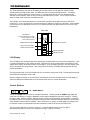
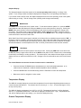
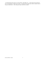
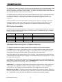
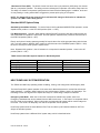
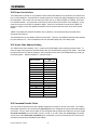
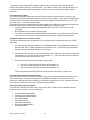
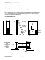
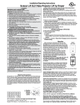
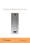
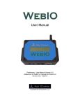
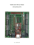
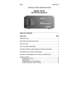
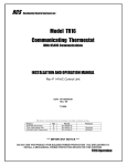
RCS
Residential Control Systems Inc.
Model TXB16
X10 Powerline
Communicating Thermostat
INSTALLATION AND OPERATION MANUAL
DCN: 141-00940
Rev 02
7/14/03
Applies to the following revisions or later:
Product
TXB16 Thermostat Kit
TS16 Wall Display Unit
HCFX HVAC Control Unit
Part No
001-00940-03
001-00910-04
001-00860-03
*** IMPORTANT NOTICE ***
DO NOT USE THIS PRODUCT FOR BUILDING FREEZE PROTECTION! YOU ARE ADVISED TO
INSTALL A MECHANICAL FREEZE PROTECTION DEVICE FOR THIS PURPOSE.
TXB16 Operation
The TXB16 thermostat provides the latest technology in a full-featured universal thermostat with X10
communications. The TXB16 has many new features including:
•
•
•
•
•
•
•
Separate Heating and Cooling Setpoints
Multistage HVAC Systems Support
Setup Mode from the Wall Display Unit
Automatic Remote Sensor Detection
Selectable X10 Decode Table
Bi-directional X10 Standard
Enhanced X10 Protocol
The TXB16 thermostat consists of two parts, a TS16 Wall Display Unit (WDU) and a HVAC Control Unit.
The Wall Display Unit provides users functions like a traditional thermostat and connects to the Control Unit
by a 4 wire cable. The Control Unit connects at the HVAC system using the standard thermostat
connections and provides the thermostatic temperature control of the system. The Control Unit also has the
X10 Power Line Interface connection.
The TXB16 now maintains separate heating and cooling setpoints. The display shows the setpoint of the
current operating mode (in Auto mode, the system keeps track of the current operating mode of the last call,
either heating or cooling). New X10 bi-directional commands have been added for a heating setpoint and a
cooling setpoint. Note that the TXB16 maintains compatibility with single setpoint protocols by continuing to
support the current SP command for both inbound commands and status reports.
In addition to the universal Standard or Heat Pump systems support, the TXB16 supports multistage
heating/cooling system outputs. The control unit can support 2 stages of heating and cooling for Standard
systems, or 3 stages of heating and 2 stages of cooling for Heat Pump systems.
The TXB16 has a convenient setup mode from the Wall Display Unit. You can set the network address, F or
C mode and easily calibrate the internal and remote sensors.
The TXB16 has automatic detection and setup of remote temperature sensors. Remotes sensors have 3
address settings that, when detected by the TXB16, will be used for specific functions such as in lieu of the
internal sensor, averaging with other sensors or an outdoor sensor.
The default X10 unit code decode table, B or P can be set to allow compatibility with existing TX15/TX15B
thermostats and control software. Changes in decode table selection by using “All lights On” or “All Units
Off” commands or Preset Dim Commands are now stored in EE prom for permanent selection even with
power cycling.
For easy configuration as a replacement for older TX15 thermostats with the “B” decode table, dipswitch
SW1 position 4 can be set to ON to force “B” decode table use.
The Bi-directional protocol is now included as standard for the TXB16.
Remote control of the TXB16 via the X10 communications protocol allows for the thermostat’s temperature,
heating and cooling setpoints, operating mode and fan functions to be monitored or changed.
A robust X10 Bi-directional protocol allows full control of all the thermostat setup and operating parameters.
Many new commands have been added to support the TXB16’s new features. Refer to the X10 protocol
document, DCN 150-00200.
DCN: 141-00940-02 7/14/03
2
TS16 Wall Display Unit
The TS16 Wall Display Unit has a LCD display and control buttons for changing the setpoint, system
operating mode and manual fan mode. The WDU also has an internal temperature sensor. The display
serves as a common display for many functions. It normally shows the current room temperature but
switches to show setpoint, mode or other functions when buttons are pushed. Two on-screen indicators
show the state of the manual fan and setback mode.
Any changes, such as the temperature or control button operations at the WDU are sent to the HVAC
Control Unit. In turn, the Control unit can send changes in setpoint or modes up to the WDU. When updates
are received, they are displayed on the LCD for 3 seconds and then the display returns to the current room
temperature.
TS16 WDU
LCD DISPLAY
Shows current temp normally.
Shows setpoint or mode
when buttons pushed.
.7.5
Setback Mode On Indicator
Manual Fan On Indicator
Setpoint Increase Button
Setpoint Decrease Button
MODE
FAN
System Mode Button
Manual Fan Button
LCD Display
The LCD display is a two digit multifunction display that normally shows the current room temperature. It has
a continuous backlight for easy viewing anytime. Whenever any of the control buttons are pushed, the LCD
display will change to show that function’s current status. The LCD display will stay in the new display mode
as long as buttons are being pushed. After 3 seconds of no activity, the display will change back to show
current temperature.
The right decimal point on the LCD display will turn on whenever manual fan is ON. The left decimal point will
flash whenever the setback mode is ON.
Remote changes in setpoint or modes that are received from the Control Unit will cause the LCD display to
switch and display the updated data for 3 seconds and then return to current temperature.
Control Buttons
UP – DOWN Buttons
The UP and DOWN buttons control the setpoint temperature. Pushing the UP or DOWN button once will
cause the LCD display to change to show the current setpoint temperature (but won’t change it). Pushing
the button again, before the display switches back to current room temperature, will decrement or increment
the setpoint value by one degree. Pushing and holding a button down will cause the setpoint to continuously
ramp up/down until the button is released. After 3 seconds of no activity, the LCD display will change back
to show the current room temperature and the new setpoint value will be sent to the Control Unit.
The max cooling setpoint is 110 deg F (43 deg C). The max heating setpoint is 106 (41 deg C).
Min setpoint is 40 deg F (5 deg C) for heating and 44 deg F (7deg C) for cooling.
DCN: 141-00940-02 7/14/03
3
Setpoint Display
The displayed setpoint shows the setpoint of the current operating mode (heating or cooling) of the
system. If you change modes, the setpoint displayed will change to the new operating mode setpoint.
If you set the mode to AUTO mode, the setpoint displayed will be the current operating mode of the system,
either heating or cooling. This will change if the operating mode changes automatically.
MODE
MODE Button
The MODE button controls the HVAC system mode. To see what mode the system is in, push the MODE
button once and the LCD display will change to show the current mode (but won’t change it). Pushing the
MODE button again while the mode is being displayed, will cause the mode and display to change to the
next mode. The system mode cycles from Off to Heat to Cool to Auto (and to EH or emergency heat for
Heat Pump systems) and back to Off again with each push of the MODE button. Any change in the system
mode will be sent to the HVAC Control Unit.
When Heat Pump HVAC system type is selected on the Control Unit, an additional system mode of “EH”, or
Emergency Heat, is included in the TS16 mode selections. EH is used when Heat Pump compressor failure
requires the use of Auxiliary Heat (heat strips) for primary heating. When EH mode is selected, the display
will alternate between current temperature and “EH” to remind you that the EH mode has been selected.
FAN
FAN Button
The FAN button controls the HVAC system’s manual fan mode. Pushing the FAN button once will turn the
fan ON and pushing it again will turn the fan to the AUTO mode (which is OFF unless the fan is automatically
turned ON by the heating or cooling operation ). The decimal point in the middle of the two digits on the LCD
display will come on when the manual fan is ON. Changes in the fan mode will be sent to the HVAC Control
Unit.
The Control Buttons can be used for other functions and in combinations.
•
Press and hold the UP/DOWN buttons simultaneously to view the Outside temperature. (If an
outdoor sensor is attached or network outside temperature data is available).
•
Press the MODE button and simultaneously press the FAN button to enter the Setup Mode.
•
Buttons are used for navigation in other modes.
Temperature Display
The WDU will normally display the current indoor temperature from the internal digital temperature sensor or
a remote sensor with address 1. The sensors have an accuracy of +/- 1°F(+/- .5°C) and the range of -67°F(55°C) to 257°F(125°C).
The WDU will display temperatures from -9°F/C to 127°F/C. Temperatures less than 0° will be displayed
down to -9 ° (temperatures lower than –9 will also be displayed, but without the – sign). Temperatures over
100° will be displayed without the leading 1 (ex: 102 will be displayed as 02°)
Outside Temperature Display
DCN: 141-00940-02 7/14/03
4
If you attached a remote temperature sensor to the WDU that is set to remote sensor address “4”, you can
view the outside temperature by pressing the UP and DOWN buttons simultaneously.
Setup Mode
The TXB16 has a new setup mode to allow the user to set the following functions from the WDU:
• X10 House Code Address
• F/C mode
• Sensor Calibration
Entering into the setup mode.
Enter the setup mode by the following procedure:
1. First press and hold the Mode button
2. Simultaneously press the Fan button.
3. The display will change to show “SU”.
4. Release all buttons.
5. The display will change to show the setup menu, starting with “Ad” (Address)
6. Select what setup function you want to change or view by pressing the Mode button to cycle
through the menu options:
“Ad” X10 Address
“FC” Fahrenheit or Celsius mode
“C1” Calibrate Internal Sensor (or Remote Sensor address 1 if attached)
“C2” (if Remote Sensor address 2 attached)
“C4” (if Remote Sensor address 4 attached)
Setting the Address
When you first enter the setup mode, the first menu selection displayed on the LCD display is “Ad”. To view
the current address setting, press the UP or DOWN button once. With the current address displayed, you
can either change the setting or exit by pressing the mode button or wait for the screen to time out. If you
want to change the address, while the current address is being displayed, use the UP/Down buttons to
select the address desired, 1 to 16, corresponding to X10 house codes A to P. (Default set to 1)
Setting the Fahrenheit or Celsius mode
In the setup mode, press the mode button to select “FC” mode. Press the UP/DOWN buttons to select F or
C mode desired. To exit press mode again to move another setup mode or wait for the screen to time out and
return to thermostat mode.
Setting the Sensor Calibration
In the setup mode, press the mode button to display the sensor calibration address, “C1”, to be calibrated.
”C1” is the internal sensor and normally that is all that will be available to calibrate unless external remote
sensors are attached. These will show up as “C1”, “C2” and “C4” in the menu selection, if present. With the
desired sensor address displayed, press the UP/DOWN buttons to change the sensor calibration to the
desired temperature. See calibration explanation below.
Exit setup mode
When you are done making changes and no button is pressed for 3 seconds, the display will automatically
exit setup mode and return to the thermostat mode and current temperature display.
Temperature Display Calibration
The TS16 WDU has the capability for the user to adjust the temperature display calibration from the WDU in
the setup mode of the internal sensor as well as all attached remote sensors.
Normally the TS16, with no attached remote sensors, will only show the internal sensor as “C1” in the
calibration setup menu. The TS16 can have additional remote sensors attached. These are addressed as
remote sensors 1, 2 (3 is not used on theTS16) and 4. If they are detected by the TS16, they will show up in
the calibration menu as additional sensors to calibrate as C2 and C4. Note that if remote sensor with
DCN: 141-00940-02 7/14/03
5
address 1 is attached it replaces the internal sensor and is becomes the “C1” sensor. See the remote
sensor section for more details.
When the desired sensor is selected in the setup menu, you can adjust its displayed temperature calibration
up or down 7 degrees by pressing the UP/DOWN buttons.
The calibration menu selections are:
C1 = calibrate internal sensor or remote sensor address 1 if attached
C2 = calibrate remote sensor address 2 (only shows up in menu if attached)
C3 = N/A, not used on the TS16
C4 = calibrate remote sensor address 4 (only shows up in menu if attached)
Remote Sensors
The TS16 Wall Display Unit has a remote sensor terminal block, J2, on the base for connection of a remote
temperature sensor. Without any remote sensor attached, the WDU uses the internal sensor for the current
temperature information. When a remote sensor is attached, the WDU will detect it automatically and will
use the remote sensor(s) according to its address selection. Modes of operation are as follows:
Address 1:
Address 2:
Address 3:
Address 4:
Use the remote sensor instead of internal sensor. (becomes C1 in the calibration setup).
Average remote sensor 2 with internal sensor or remote sensor 1. (C2 in the calibration setup)
Not used with the TS16
This remote sensor is used for an outside temperature sensor. (C4 in the calibration setup)
Table of Remote Sensor Functions and Sensor Addresses
Function
Remote Addr 1 Remote Addr 2 Remote Addr 3
Use internal sensor only
No
No
Not used
Use remote sensor only
Yes
No
with TS16
Average internal and one remote
No
Yes
Average two remotes (only 2)
Yes
Yes
Outside temp display on WDU
NA
NA
* optional outside temp sensor can be used with any other sensor address.
Remote Adrr 4
*
*
*
*
Yes
When averaging sensors are used, the average temperature is displayed on the WDU and reported to the
HVAC control unit. You cannot view an individual remote averaging sensor temperatures as the main
thermostat display or report individual sensor temperatures on the communication port. However, you can
check the individual sensor temperatures by going to the calibration setup menu and selecting the sensor
address. You can view the outside temperature by pressing both the UP/DOWN buttons simultaneously.
WDU Error Displays
“CF” Error Display
If the WDU is not properly wired or if communications to the Control Unit is interrupted, the LCD display will
display “CF” to denote communications failure. Momentary display of “CF” caused by bad or lost data, will
clear automatically when data communications is restored.
If the “CF” display stays on, check wiring for problems. A continuous “CF” display may indicate a problem
with the Control Unit or the WDU itself.
“SF” Error Display
DCN: 141-00940-02 7/14/03
6
If the WDU detects that a sensor is not responding, it will display “SF”. In most cases this will clear itself
when communications is restored to the sensor. A continuous “SF” display may indicate a problem with the
wiring or the WDU itself. Check wiring and replace the WDU as needed.
DCN: 141-00940-02 7/14/03
7
TXB16 HVAC Control Unit
The TXB16 HVAC Control Unit works in conjunction with the Wall Display Unit to provide thermostatic control
of the HVAC system. In addition, the Control Unit can receive X10 commands for remote control of the
setpoints, temperatures and modes of the thermostat. The TXB16 X10 bi-directional protocol also allows the
unit to transmit information via the pre-set dim commands.
The TXB16 Control Unit connects to the HVAC system the same as, and in place of, a standard thermostat.
It is usually mounted near the HVAC system, although it can be mounted anywhere convenient. It is
connected to the WDU by a 4 wire cable, either standard thermostat wiring or typically Cat 3/5 in new
construction.
Actual thermostatic control of the HVAC system is provided by the Control Unit. Changes in the current
temperature, setpoint, system or fan modes are sent to the Control Unit either from the WDU or via X10
commands. The Control Unit monitors this information and operates the HVAC system accordingly.
HVAC System Compatibility
The TXB16 works with almost all heating and cooling systems, including standard Gas/Electric, Heat Pump,
Radiant, or Hydronic systems and with single or multi-stage systems. Compatible with single or separate
transformer heating/cooling systems.
System Type
Gas
Electric
Heat Pump
Radiant
Hydronic
Heating Stages
2
2
3
2
2
Cooling Stages
2
2
2
2
2
Notes
Single or split transformer
Selectable Fan with Heat
Selectable Changeover with Heat or Cool
Pump output
STANDARD GAS/ELECTRIC HVAC SYSTEMS OPERATION
The TXB16 has Standard HVAC system operating modes of Heating, Cooling and Auto changeover.
In the HEAT mode, the stage 1 heating will be turned on at one degree below the heating setpoint and will
turn off at the setpoint. In the COOL mode, the stage 1 cooling will be turned on at one degree above the
cooling setpoint and will turn off at the setpoint. This is referred to as the setpoint delta.
Second stage heating/cooling deltas are factory set at 3 degrees. This means that second stage will come
on when the delta from setpoint reaches 3 degrees. Second stage heating/cooling calls will stay on until the
first stage setpoint is satisfied.
In the AUTO mode, the system will maintain the heating or cooling setpoints and switch automatically from
heating mode to cooling mode as needed. There is a deadband between heating and cooling setpoints that
keeps the two setpoints from overlapping. This is set to 4 degrees.
Setpoint Push. If you adjust the heating setpoint to be less than 4 degrees from the cooling setpoint, the
cooling setpoint will be pushed to maintain the 4 degree deadband separation. Same for adjusting the
cooling setpoint, if you get within the deadband separation, the heating setpoint will be pushed.
Minimum run time (MRT). The HVAC Control Unit has a minimum run time set to 6 minutes. Whenever a
heating or cooling call turns on, the system will run a minimum of 6 minutes even if the call is satisfied before
then. If the system is set to Off mode, the MRT will be canceled and all operation stopped.
DCN: 141-00940-02 7/14/03
8
Minimum Off Time (MOT). The HVAC Control Unit has a short cycle protection (SCP) delay of 6 minutes
after any compressor operation. This delay prevents a subsequent compressor call until the delay times out.
This delay is to allow the compressor head pressure to bleed off before starting again. In addition, at the end
of every heating or cooling call the MOT is triggered to prevent rapid cycling of the system.
NOTE: The Status LED on the Control Unit circuit board will change to flash twice to indicate the
system is in a MRT or MOT delay period.
Standard HVAC System Setup
Standard System Mode Selection. To set the Control Unit for standard GAS/ELECTRIC operation, set the
dipswitch SW1 position 1 to the STD SYS position (SW1-1 = OFF).
Fan Mode Selection. Normally, GAS heating systems DO NOT require fan calls along with the heat call
due to automatic fan operation in the furnace. For Gas systems, dipswitch SW1 position 2 should be set to
the STD FAN position (SW1-2 = OFF).
Electric and hydronic heating systems generally DO require that a fan call be generated along with the heat
call. For these systems, dipswitch SW1 position 2 should be set to the FAN/HEAT position (SW1-2 = ON).
Be sure to check your HVAC system’s requirements.
Note: Dipswitch SW1 position 3, the CO selection is not required for standard systems. Leave in the Off
position (SW1-3 = OFF)
TXB16 Control Unit HVAC System Outputs for Standard Systems
Operating Mode
Manual Fan
Heating Stage 1
Heating Stage 2
Cooling Stage 1
Cooling Stage 2
Outputs (no Fan with Heat)
G
W1
W1, W2
Y1, G
Y1, Y2, G
Outputs ( Fan with Heat)
G
W1, G
W1, W2, G
Y1, G
Y1, Y2, G
HEAT PUMP HVAC SYSTEM OPERATION
The TXB16 has Heat Pump operating modes of Heating, Cooling, Auto changeover and Emergency Heat.
The Heat Pump HVAC system operation is the same as for Standard systems for normal first and second
stage operations. In addition, Heat Pumps may have a third stage of heating, which is for heat strips. The
third stage comes at 5 degrees from setpoint and stays on until the stage 1 setpoint is satisfied.
Emergency Heat Mode. When the Control Unit is selected as a Heat Pump system, there is an
Emergency Heat Mode that can be selected from the WDU mode menu. In the event of a compressor failure,
the “EH” mode can be selected. When in this mode, the heat strips (W1 output) will be used for stage one
heat calls. This mode is for temporary use until the compressor can be repaired.
Heat Pump systems have the same Minimum Run Time and Short Cycle Protection /Minimum Off Time
delays as Standard systems.
Heat Pump systems have a different HVAC system setup, which is described below.
DCN: 141-00940-02 7/14/03
9
Heat Pump HVAC System Setup
Heat Pump Mode Selection. For Heat Pump operation, set SW1-1 to the HP SYS position (ON).
Fan Mode Selection. Set the Fan selection, SW1-2, to the STD FAN position (OFF).
Change Over Selection. Heat pump systems change from heating to cooling by reversing the direction of
Freon flow in the system. This change over is controlled by the CHANGEOVER (CO) output from the Control
Unit (sometimes this is referred to as the reversing valve).
Most heat pump systems are designed to work normally in the heating mode and require a change over
output for cooling. Set dipswitch SW1 position 3 to the CO/CL position (SW1-3 = OFF) for this type system.
Check your HVAC system requirements for correct settings.
If your system requires changeover with heating, set SW1 position 3 to the CO/HT position (SW1-3 = ON).
Changeover Relay Operation: The changeover relay output stays ON after a heating/cooling call for the
duration of the minimum off delay period. If another call occurs before the delay period expires, the CO relay
will already be on and this avoids continuously cycling the CO valve on/off for each call.
TXB16 Control Unit HVAC System Outputs for Heat Pump Systems
Operating Mode
Manual Fan
Heating Stage 1
Heating Stage 2
Heating Stage 3
Cooling Stage 1
Cooling Stage 2
Emergency Heat
Changeover with Cool
G
Y1, G
Y1, Y2, G
Y1, Y2, G, W1
Y1, G, O
Y1, Y2, G, O
W1, G
Changeover with Heat
G
Y1, G, O
Y1, Y2, G, O
Y1, Y2, G, O, W1
Y1, G
Y1, Y2, G
W1, G
Control Unit Status LEDs
The Control Unit has LEDs on the circuit board to show system status and output states. The STATUS LED
will normally blink on and off slowly as a system heartbeat. During MRT/MOT delay periods, the STATUS
LED will blink twice for each heartbeat. The other LEDs indicate the operation of the control unit output
relays. When the LED’s are on, the output relay is on.
LED
H1
Fan
C1
C2
H2/CO
Function
Heat stage 1 output (Heat stage 3 for HP systems)
Fan output
Compressor stage 1 output
Compressor stage 2 output
H2 = Heat stage 2 output for Standard HVAC systems
CO = Changeover valve output for Heat Pump HVAC
systems.
DCN: 141-00940-02 7/14/03
10
Control Unit Output
W1
G
Y1
Y2
W2
O
X10 OPERATION
X10 Power Line Interface
The TXB16 Control Unit has an X10 powerline carrier interface that allows X10 commands to be received over
the 110 VAC powerline. Commands from remote systems can change the setpoint temperature and mode of
the Thermostat. The Control Unit connects to the power line by an external PSC05 (or TW523) X10 Power
Line Interface Module. X10 commands received by the Control Unit are decoded to a new setpoint or a new
mode and are sent to the WDU to update its display. When X10 commands are received, the WDU will
switch it’s display to show the updated information for three seconds and then return to the current temp
display.
TXB16 Thermostats also transmit information when queried by X10 commands using the preset dim bidirectional command set.
The thermostat has an X10 address called a “House Code”. There are 16 possible X10 House Codes referred
to by the letters A to P. The X10 address is set from the Wall Display Unit in the Setup mode.
X10 House Code Address Setting
The TXB16 House Code address, A to P, is set from the Wall Display Unit by entering the setup mode. To
enter the setup mode, press and hold the Mode button and simultaneously press the Fan button. This enters
the setup mode and “Ad” will be displayed. Set the desired house code by UP/DOWN buttons according to
the following table. Default is address 1, or House Code A.
WDU Address
1
2
3
4
5
6
7
8
9
10
11
12
13
14
15
16
X10
HOUSE CODE
A
B
C
D
E
F
G
H
I
J
K
L
M
N
O
P
X10 Command Decode Tables
The X10 communications protocol was originally designed to turn lights on and off or dim them. The TXB16
thermostats responds to X10 commands by decoding them into commands to change thermostat setpoints
and modes. As such, there are two types of X10 commands that the TXB16 will respond to: the more simple
Unit Code commands (32 commands), such as “A1 ON” or “A1 OFF” which are receive only commands;
and the more robust Preset Dim commands (512 commands), such as “A4 Preset Level 6%” which are bidirectional (received and transmitted by the TXB16).
DCN: 141-00940-02 7/14/03
11
The specific X10 commands that the TXB16 Control Unit can receive and how they are decoded into
setpoints and modes is defined by a “Decode Table”. The TXB16 includes 3 Unit Code decode tables, B, P,
L and the Preset Dim Bi-Directional decode table. See the X10 Protocol manual #150-00200 for further
information.
Unit Code Decode Tables
Unit Code Decode tables us the simple direct X10 commands sent by devices like the X10 mini or maxi
controller, most all home automations systems and many security systems. They consist of messages with
a House Code and Unit Code command sequences of House Code/Unit Code/Command such as A 1 ON
(A= house code, 1 = unit code, On=command).
There are three Unit Code Command Decode Tables available in the TXB16, the P Decode table (default), the
B Decode Table and the L Decode Table. Each has slightly different decode schemas.
• The P decode table is the primary and default table and is the same as used by the TX15-B
thermostat.
• Non bi-directional TX15s used the B decode table.
• The L table is a special limited ON/OFF/SETBACK decode table for use with security systems that
can have only one X10 House code and that must be shared with lighting and the thermostat.
Setting the Default Unit Code Decode Table.
The TXB16 is default set to the P decode table. You can set/change the decode table used by the TXB16
three ways.
1.
For quick and easy setting the TXB16 to be compatibility with older TX15 software that used the “B”
Decode Table, set the control unit dipswitch SW1 position 4 ON. In this position, the decode table
selection cannot be overridden with any X10 commands.
2.
Use the Unit Code All Lights On (ALO) or All Units Off (AUO) commands. ALO will set the unit code
decode table to “B” and AUO will set the decode table to “P”. These changes are stored in EEProm
memory and will not be lost by a power cycle.
3.
Use the Preset Dim commands to select the decode table.
a.
b.
c.
Unit code 4, preset level 90% will set the decode table to “P”
Unit code 4, preset level 94% will set the decode table to “B”
Unit code 4, preset level 97% will set the decode table to “L”
These changes are also stored in EEProm memory and will not be lost by a power cycle.
Unit Code and Preset Dim Command Control
Unless otherwise turned off by preset dim commands, both Unit Code and Preset Dim commands can be
used simultaneously. Unit Code commands can be inhibited by a preset dim command (Unit 4 55%).
Preset Dim commands can also be inhibited by a Preset Dim command (Unit 4 61%). Note that the Preset
Dim Command “Preset ON” (Unit 4 58%) command is always enabled.
Other Preset Dim Control Commands
The Preset Dim command set contains many other control options. Refer to the X10 protocol manual for
details on these commands. They are listed below.
•
•
•
•
•
•
•
•
Unit Code Commands ON/OFF
Preset Dim Commands ON/OFF
Acknowledgement Mode ON/OFF
Echo Mode ON/OFF
Safe Mode ON/OFF
Autosend Mode ON/OFF
Dual Setpoint Mode ON/OFF
Test Mode ON/OFF
DCN: 141-00940-02 7/14/03
12
TXB16 Installation
STOP
Before proceeding with removing an existing thermostat and installing the TXB16,
Read the following important steps.
1.
2.
3.
4.
Record existing wiring information on the enclosed wiring form.
Perform the TXB16 bench test
Check WDU wiring BEFORE applying power to control unit.
Be sure to install a freeze protection device as required.
Installation Overview
Standard thermostat wiring vs TXB16 in retrofit applications.
Heating &
Cooling
System
OLD
4, 5 or 6 wires
18Ga thermostat wiring
Thermostat
Insert Control Unit into
the thermostat wiring
Replace
Thermostat with
Wall Display Unit
Heating &
Cooling
System
NEW
4 Wires
TXB16
Control
Unit
TXB16
Wall Display Unit
4,5 or 6 wires as
original
installation
Freeze Protection.
In cold climates that require the heating system to be used for building freeze protection, a mechanical
backup freeze protection device MUST be installed on the heating system. This can be a simple mechanical
heating thermostat or a preset thermoswitch installed in the heated area.
40-45°
Mechanical
Thermostat or
Thermoswitch
R
Red Wire
W
White Wire
24VAC R
Heat W
Heating
System
Thermostat connections
DCN: 141-00940-02 7/14/03
Wire across Heater R/W terminals.
13
TXB16 Wall Display Unit Installation
WDU Location Choose a location that best represents the temperature of the area to be controlled. Avoid
locations that are subject to drafts, from doors and windows, or areas with direct sunlight exposure.
WDU Mounting Route the wires to the WDU through the access hole in the back of the case. Mount the
WDU to the wall with the screws and anchors provided. Be sure to plug any large access hole in the wall
with sealer or insulation to prevent wall drafts from affecting WDU operation.
WDU Prewiring The recommended wiring to the WDU from the Control Unit should be a two twisted pair
cable, 24 Ga minimum. Cat 3 or 5, 4 pair cabling is acceptable. In retrofit applications the existing thermostat
wiring (a least 4 wires) may be adequate. However, such non-twisted wiring may be subject to interference
due to noise from adjacent wiring or other sources.
Wiring to the Wall Display Unit
OPENING AND CLOSING THE WDU CASE
BASE
TO CLOSE
TS16 WDU
BASE
Hook TOP here
and rotate into
base. Be sure
pins engage in
connector ok.
J2
J1
G
+5
C
D
CLOSE
G
+12
C
D
WIRING
ACCESS
HOLE
1 POWER GND
2 POWER +
3 COM CLOCK
4 COM DATA
OPEN
TO OPEN
For Remote Sensor
PULL FROM LOWER CORNERS
WDU WIRING DIAGRAM
TXB16 WALL DISPLAY UNIT
** CAUTION **
DO NOT MISWIRE
WDU
CONNECTIONS
OR
DAMAGE WILL
RESULT
TXB16 CONTROL UNIT
WDU
GND
GND
G
+12V
+12VDC +V
CLOCK
C
DATA
D
J1
CLK
DATA
TWISTED PAIR 22 GA WIRE RECOMMENDED
Remote Sensor Wiring
DCN: 141-00940-02 7/14/03
14
The TS16 WDU has an addition connector, J2, on the WDU base for connection of an external remote
temperature sensor. Follow the wiring diagram with the remote sensor to connect to the WDU.
DCN: 141-00940-02 7/14/03
15
TXB16 Control Unit Installation
Location and Mounting
Install the TXB16 Control Unit in a protected, convenient, INDOOR location near the HVAC system or in a
service accessible area such as an equipment closet or garage.
Mount the Control Unit in a vertical position on a wall or sturdy structural member. The unit may be mounted
on the HVAC system but care should be taken to avoid the hot burner section or high vibration areas.
Control unit wiring
The TXB16 HVAC Control Unit is connected to the HVAC system and to the Wall Display Unit as well as the
X10 communication interface and power connections.
Control Unit to WDU wiring
Control Unit
WDU
TS16
GND
G
+12VDC +V
CLOCK
DATA
C
4 wire connection to
Wall Display Unit
Thermostat wiring or
22 Ga Twisted pair
(Cat 3/5 wiring OK)
J1
GND
+12V
CLK
DATA
D
Control Unit to HVAC System wiring
Electrically, the Control Unit looks like a standard thermostat to your HVAC system. All connections to the
HVAC system are made at the normal thermostat connections on the HVAC unit.
You are advised to refer to your HVAC system’s documentation for specific information on its thermostat
connections and setup requirements. You must know the following:
1.
2.
3.
HVAC system type: Gas, Electric, Heat Pump, Radiant, Hydronic
Fan requirement: No fan with Heat or Fan with Heat
For Heat Pump systems: Changeover with cool or with heat. (O or B connection)
Note on retrofit wiring. You may note (and be sure to note on the wiring form) that you have additional
wires when you disconnect your old thermostat. Usually these wires are for auxiliary functions such as filter
or trouble indicators. For Heat Pump systems there may be emergency heat (EH) wiring or both O and B
changeover connections. These wires are not used in the TXB16 installation and, in most cases, these extra
wires are not required for normal HVAC system operation.
Refer to the following HVAC wiring diagrams for the type of HVAC system, Standard Or Heat Pump, that you
have.
DCN: 141-00940-02 7/14/03
16
HVAC System Wiring
Diagram 1 - Standard Gas or Electric System Wiring
IMPORTANT!
Cut jumper JP2 for systems with separate Cooling and
Heating system transformers.
Wire RC to Cooling system transformer and RH to heating
system transformer.
TXB16 Control Unit
RC=RH
Standard HVAC System
SW1
STD/HP
FAN/HT
CO C/H
S4
JP2
1
2
3
4
HVAC
SYSTEM
RC
24VAC
RH
OFF ON
W1 Heat 1
THERMOSTAT CONNECTION
C 24VAC Common
Red
R 24VAC Return
White
W1 Heat Stage 1
G Fan
Green
Y1 Comp 1
Yellow
Y2 Comp 2
Orange
Y2 Comp Stage 2
W2 Heat 2
Black
W2 Heat Stage 2
G Fan
Y1 Comp Stage 1
J5
Typical thermostat wiring color
codes
Standard HVAC System Setup Notes:
Single Stage Systems use W1 for heating stage 1, and Y1 for cooling stage 1.
Two Stage Heating systems use W1 for stage 1 and W2 for stage 2 heating.
Two Stage Cooling systems use Y1 for stage 1 and Y2 for stage 2 cooling.
If you have an integrated heating and cooling system with a single transformer, do NOT cut jumper JP2 and
wire the system red wire to either RH or RC. This is typical of most central systems.
If you have a separate heating and cooling systems with separate transformers, cut jumper JP2 and wire the
heating red wire to RH and run the cooling red wire to RC.
Dipswitch SW1 Setup
1.
2.
3.
4.
Set SW1-1 (position 1) to the STD position. (Off or to the left)
Set SW1-2 (position 2) to the correct setting for your HVAC system.
a. Gas furnaces do not require fan outputs for heating calls. Set SW1-2 to the Off or to the left.
b. Electric furnaces do require fan outputs for heating calls. Set SW1-2 to the On or to the right.
SW1-3 (position 3) is not applicable to standard systems, leave Off or to the left.
SW1-4 (position 4) is used to select the default X10 decode table.
DCN: 141-00940-02 7/14/03
17
HVAC System Wiring
Diagram 2 - Heat Pump System Wiring
IMPORTANT!
Do not cut JP2 for Heat Pump Systems.
RC and RH are common for Heat Pumps.
TXB16 Control Unit
RC=RH
Heat Pump HVAC System
SW1
STD/HP
FAN/HT
CO C/H
S4
1
2
J5
JP2
HVAC
SYSTEM
RC
24VAC
RH
3
4
OFF ON
W1 Heat 1
THERMOSTAT CONNECTION
C 24VAC Common
Red
White
G Fan
Green
Y1 Comp 1
Yellow
Y2 Comp 2
Orange
O CO
Black
R 24VAC Return
W1 Heat Stage 1
G Fan
Y1 Comp Stage 1
Y2 Comp Stage 2
O Changeover Valve
Typical thermostat wiring color
codes
Heat Pump HVAC System Setup Notes:
Single Stage Compressor Systems use Y1 for stage 1 heating/cooling, and W1 for stage 2 heating (heat
strips).
Two Stage Compressor Systems use Y1 for stage 1 and Y2 for stage 2 heating/cooling, and W1 for stage 3
heating (heat strips).
NOTE: You must configure the Changeover valve setting to work correctly with your HVAC system.
Set Dipswitch SW1 as below for correct changeover with cool (typical) or change over with heat.
Dipswitch SW1 Setup
1.
2.
3.
4.
Set dipswitch SW1-1 (position 1) to Heat Pump position. (On or to the right)
SW1-2 (position 2) is not used for Heat Pumps. Leave Off or to the right.
Set SW1-3 (position 3) to the correct setting for your Heat Pump system.
a. For systems with changeover with cooling, Set SW1-3 to CO/C position. (Off or to the left)
b. For systems with changeover with heating, Set SW1-3 to CO/H position. (On or to the right)
SW1-4 is used to select the default X10 decode table .
DCN: 141-00940-02 7/14/03
18
Wiring to the X10 Powerline Interface Module
The X10 interface on the Control Unit is the RJ11 jack, J2. It is connected to an X10 power line interface
module, Model PSC05 (or TW523), by the four (4) wire modular phone cable provided.
TXB16 CONTROL UNIT
120V OUTLET
X10 PLI
MODULE
X10 PLI
RJ11
J2 JACK
4 WIRE MODULAR CABLE
IMPORTANT NOTE: Use the Modular Cable Provided. If you do not, be sure the cable is the correct
type. The Cable must be 4 wire (NOT 2), and reversing.
If you are having X10 communication problems or in doubt about the cable, check the cable with the simple
inspection shown below.
Place the ends of the cable
side by side and verify the
color codes of the
conductors are in reverse
order as shown here.
BRGY
YGRB
CORRECT CABLE WIRING
BRGY
BRGY
INCORRECT CABLE WIRING
DO NOT USE THIS CABLE
Power Connection
The TXB16 Control Unit requires 12VDC, 200ma max. Connect the provide transformer to jack J4.
Center Ground
J4
12VDC
JACK
12VDC
POWER
TRANSFORMER
NOTE! Be sure to plug the transformer into an outlet that is NOT switched
DCN: 141-00940-02 7/14/03
19
System Checkout
It is strongly recommended that you hook-up and run a simple bench test before installing the TXB16. Not
only will this save you time in system checkout but will also familiarize you with the thermostat’s operation.
THERMOSTAT BENCH TEST
1. Connect the Wall Display Unit to the Control Unit with a short (12-24 inch) 4 wire cable.
2. Before power up, set the Control Unit dipswitch, SW1, to ALL OFF
3. Connect the 12VDC transformer to the Control Unit.
4. Plug the transformer into a 110VAC outlet and apply power. Verify Control Unit Status LED is blinking.
5. Verify the WDU display comes on and shows the current temperature.
a. If no display and backlights are not on, check wiring and power at the Control Unit.
b. If a “CF” display is shown on the WDU, double check your wiring to the Control Unit.
d. Do not proceed until the current temperature is displayed on the WDU.
6. With the current temperature displayed on the WDU, we have verified communication between it and the
Control Unit is OK. Any communication problems will result in a “CF” (Communications Failure) display on
the WDU and must be fixed before proceeding. If all is OK with the WDU proceed to the next step.
7. Press the Fan button on the WDU. The Control Unit’s Fan LED and relay should turn on.
8. Press the Fan button again. The Fan LED and relay should turn off.
9. Press the Mode button until the WDU is showing “H” for Heat Mode.
10. Press the Setpoint Up button until the setpoint is above the current temperature. The Heat LED and relay
should come on. (If they don’t, make sure the Status LED is not flashing twice indicating minimum off
delay…wait until LED stops flashing twice before proceeding).
11. Press the Mode button until the WDU is showing “O” for OFF. The Heat LED and relay will turn OFF.
12. Wait 6 minutes for the minimum off delay to expire. The Status LED will stop flashing twice.
13. Press the Mode button until the WDU is showing “C” for Cool Mode.
14. Press the Setpoint Down button until the setpoint is below the current temperature.
15. The Compressor and Fan LEDs and relays should turn on.
16. Press the mode button until the WDU is showing “O” for OFF Mode.
17. All LEDs and relays should turn off.
18. When you have successfully completed all these tests, you have verified that the TXB16 is working
correctly.
X10 QUICK TEST
Requires an X10 Mini-Controller (PHC01) or a Maxi-Controller (PHC02).
1.
2.
3.
4.
5.
6.
7.
With the TXB16 connected as above, proceed with connecting the PSC05 X10 Interface Module.
Connect a four wire modular phone cable to the Control Unit.
Connect the other end of the cable to the PSC05 X10 Interface Module.
Plug the PSC05 X10 Interface Module into a 110VAC outlet.
Plug an X10 Controller in the outlet.
Set the House Code on the X10 controller to match the TXB16 Control Unit (use default address A)
Send Unit code ON and OFF commands from the X10 controller and verify that the WDU display shows
the correct response to each command sent per the X10 Decode Table selected.
8. If you have difficulty receiving X10 commands, double check the modular cable, the X10 Interface Module
and the House Code settings.
9. NOTE: The LED on the Powerline Interface Module should blink with each command sent from
the X10 controller.
10. If the TXB16 responds properly to the X10 commands, proceed with installation.
DCN: 141-00940-02 7/14/03
20
It is recommended that you install the TXB16 and Control Unit and then rerun these quick tests BEFORE
you connect the controller to the HVAC system. You will be confident that the TXB16 is working correctly
before you attempt to interface to the HVAC system.
DCN: 141-00940-02 7/14/03
21
HVAC System Testing
If you have difficulty with the HVAC system operation, you can perform the following test to verify the HVAC
system is operational.
Thermostats, like the TXB16, are just switches to the HVAC system as shown in the diagram below.
This is a simplified example of a thermostat and a standard HVAC wiring diagram. The HVAC system
operation can be tested by duplicating the thermostat switch operation by shorting across the thermostat
terminals on the HVAC system.
HVAC SYSTEM
STANDARD GAS/AC
TYPICAL THERMOSTAT
C 24VAC COMMON
24VAC
R 24VAC HOT
FAN
G FAN
HEAT
W HEAT
COMP
Y COMP
Thermostat
Connection
FAN
RELAY
GAS
VALVE
COMP
RELAY
Note: The HVAC system and thermostat connection voltage is 24VAC. This is a safe voltage to work
with but be careful to avoid shorting the 24VAC common (C) and 24VAC return (R) terminals. This
may blow a fuse in the HVAC system.
Standard HVAC System Quick Test
You can perform a quick test of the HVAC system by shorting across the appropriate thermostat terminals
on the HVAC thermostat connector. Use a short 6 inch wire to connect across the following terminals.
Function Test
Fan
Heating
Cooling
HVAC Terminals
R to G
R to W
R to Y and G
Result
Fan should come on
Heat cycle should start for heating
Compressor and Fan should start for cooling
Heat Pump System Quick Test
Similarly, you can test Heat Pump operation by shorting across the following terminals. Heat pump
operation is determined by compressor calls in conjunction with changeover (O) outputs. You must know
what your system CO type is (CO with Cool (typical) or CO with Heat). You should have configured the
TXB16 control unit for correct CO type, refer to this setting. Heat Pump systems have an additional O
terminal.
Function Test
Fan
Heating
HVAC Terminals
R to G
R to Y and G
Cooling
R to Y and G and O
Result
Fan should come on
Compressor and Fan should start and Heating
occurs.
Compressor and Fan should start.
CO valve operates and Cooling occurs.
Note: if you have the CO selection incorrect you will get cooling when you expect heating and vice versa.
DCN: 141-00940-02 7/14/03
22
RCS
TXB16 Wiring Diagram
TXB16 CONTROL UNIT
HCFRX
REV G
+12VDC +V
HVAC SYSTEM
STD/HP 1
FAN/HT 2
H1
HVAC
JP2 SYSTEM
C1
Red
C2
W1 HT1
White
H2/CO
G FAN
Green
FAN
J1
GND
+V
CLOCK
C
CLK
DATA
D
DATA
THERMOSTAT CONNECTOR
RC
24VAC
RH
OFF ON
WDU
G
STATUS
CO C/H 3
S4 4
TS16
WALL DISPLAY UNIT
GND
RC=RH
SW1
U1
NOTE: Jumper JP2 is factory installed for
common transformer heating and cooling
systems (RC=RH). When this jumper is
installed, only one red wire connection
(either RC or RH) is required from the HVAC
system. Cut jumper JP2 for systems
with separate RC and RH 24VAC
transformers.
U3
U5
C - 24VAC Common
Y1 C1
Yellow
Y2 C2
Orange
W2 HT2
O CO
R - 24VAC Return
W1 – Heat Stage 1
G – Fan
Y1 – Comp Stage 1
Y2 - Comp Stage 2
Black
W2 – Heat Stage 2 or
O – Changeover (HP)
J5
J4
J2
X10 PLI
12VDC
JACK
Typical thermostat wiring
color codes
X10
Powerline
Interface
12VDC
POWER
TRANSFORMER
DIPSWITCH SW1 SETTINGS (White is switch position)
OFF - ON
STANDARD OR HEAT PUMP SYSTEM SELECTION, SW1-1
STD Sys 1
HVAC Systems can be either Standard Gas/Electric systems or Heat Pump systems. Set SW1-1 to
STD SYS (OFF) for Gas/Electric systems (default). For Heat Pump systems set to HP SYS (ON)
STANDARD FAN OR FAN WITH HEAT SELECTION, SW1-2
STD Fan 2
This switch in not used for Std Gas or Heat Pump systems. For these systems SW1 position 2
should be STD FAN position (Off). For electric heat HVAC systems and others that require a fan
output with heat calls, SW1-2 should be in the ON position.
CHANGE OVER WITH COOL OR WITH HEAT SELECTION, SW1-3
CO/Cool 3
HP Sys
Fan/Heat
CO/Heat
This sw itch in not used for Standard Systems, for Heat Pump systems Only.
Heat Pump systems require a change over (sometimes referred to as reversing valve) output to switch
between heating and cooling. Most Heat Pump systems are change over with cooling and SW1-3
should be set to CO/COOL (OFF) position. Check your HVAC system documentation to determine what
your system requires. If your system requires change over with heat, set SW1-3 to the CO/HT (ON)
X10 DECODE TABLE SELECTION, SW1-4
This switch overrides the Decode Table options. In the OFF position, the default table is the “P”
decode table. In the ON position, the “B” decode table is the default. This allows compatibility
with older TX15 software. In the Off mode, other decode table selection commands are
enabled, in the On mode, all other decode selection commands are inhibited.
DCN: 141-00940-02 7/14/03
23
P Decode S4
Table
B Decode
Table
Note: The default SW1 switch setting is all OFF. Standard System, No Fan/Heat, CO/Cool, P decode table
DCN: 141-00940-02 7/14/03
24