1
Operator's
Manual
CRRFr MRN
28" SNOW THROWER
Model No. 247.883951
,, SAFETY
o ASSEMBLY
OPERATION
MAINTENANCE
PARTS LIST
o ESPANOL
CAUTION" Before using this
product, read this manual and
follow all safety rules and operating
instructions.
Sears Brands
Management
Corporation,
Visit our website:
Hoffman
www.craftsman.com
Estates,
IL 60179, U.S.A.
Form I/o 769-08200B
(June 10,2013)
WarrantyStatement
..............................
SafeOperationPractices......................
Assembly
....................................
Operation..................................
Service&Maintenance
.......................
Page2
Pages3-6
Pages8-13
Pages14-17
Pages18-23
Off-Season
Storage
.............................
Page24
Troubleshooting
...............................
Page26
PartsList...................................
Pages28-44
RepairProtectionAgreement
....................
Page47
Espa_ol
........................................
Page48
CRAFTSMAN
TWOYEARFULLWARRANTY
FORTWOYEARS
fromthedateof purchase,
this productiswarrantedagainstanydefectsin materialor workmanship.
Defectiveproductwill receivefree
repairorfreereplacement
if repairisunavailable.
ADDITIONALLIFETIME
LIMITEDWARRANTY
on UPPERand LOWERCHUTE
FORASLONG
ASITISUSED
bytheoriginalownerafterthesecondyearfromthedateofpurchase,the
upperandlowerchuteofthissnowthrowerare
warrantedagainstanydefectsin materialor workmanship
asverifiedbya Sears
authorizedserviceprovider.With proofofpurchase,
youwill receivea new
chutefreeofcharge.Youareresponsible
for thelaborcostofinstallationandanycostincurredto verifythedefect.
Forwarrantycoverage
detailsto obtainrepairor replacement,
visitthewebsite:www.craftsman.com
ThiswarrantycoversONLY
defectsin materialandworkmanship.
Warrantycoverage
doesNOTinclude:
•
Expendable
itemsthatcanwearoutfrom normalusewithin thewarrantyperiod,includingbutnotlimitedto augers,augerpaddles,drift cutters,skid
shoes,shaveplate,shearpins,sparkplug,air cleaner,belts,andoilfilter.
•
Standard
maintenance
servicing,oil changes,
ortune-ups.
•
Tirereplacement
orrepaircausedbypunctures
from outsideobjects,suchasnails,thorns,stumps,orglass.
•
Tireor wheelreplacement
or repairresultingfrom normalwear,accident,or improperoperationormaintenance.
•
Repairsnecessary
becauseofoperatorabuse,includingbutnot limitedto damagecausedbyover-speeding
theengine,orfrom impactingobjectsthat
bendtheframe,augershaft,etc.
•
Repairsnecessary
becauseofoperatornegligence,
includingbutnot limitedto, electricalandmechanical
damagecausedbyimproperstorage,failureto
usethepropergradeandamountofengineoil,orfailureto maintaintheequipmentaccording
to theinstructions
containedinthe operator's
manual.
•
Engine(fuelsystem)cleaningorrepairscausedbyfueldeterminedto be contaminated
or oxidized(stale).Ingeneral,fuelshouldbe usedwithin 30days
ofitspurchasedate.
•
Normaldeteriorationandwearoftheexteriorfinishes,or productlabelreplacement.
Thiswarrantyisvoidif thisproductiseverusedwhileprovidingcommercial
services
or if rentedto anotherperson.
Thiswarrantygivesyouspecificlegalrights,andyoumayalsohaveotherrightswhichvaryfrom stateto state.
SearsBrandsManagement
Corporation,
NoffmanEstates,
IL60179
Engine Oil:
5W-30
Model Number
Fuel:
Unleaded Gasoline
Serial Number
Engine:
MTD
Date of Purchase
Record the model number, serial number,
and date of purchase above.
© Sears Brands, LLC
2
Thissymbolpointsout importantsafety instructionswhich, if not
followed, couldendangerthe personalsafetyand/or property of
yourself and others.Readandfollow all instructions in this manual
beforeattempting to operatethis machine.Failureto complywith these
instructions
may resultin personalinjury.Whenyou seethis symbol, HEED
ITSWARNING!
CALIFORNIA
PROPOSITION
65
EngineExhaust,someof its constituents,and certain vehiclecomponents
containor emit chemicalsknownto Stateof Californiato causecancerand
Thismachinewasbuilt to beoperatedaccordingto the safeoperation
practicesin this manual.Aswith anytype of powerequipment,
carelessnessor error on the part of the operatorcanresultin seriousinjury.
Thismachineiscapableof amputating fingers, hands,toesandfeet and
throwingdebris. Failureto observethefollowing safety instructions
could
resultin seriousinjuryor death.
Your Responsibility--Restrict the useof this powermachineto
personswho read,understandandfollow the warningsand instructionsin
this manualandon the machine.
SAVETHESEINSTRUCTIONS!
birth defectsor other reproductiveharm.
TRAINING
Disengage
all controlleversbeforestartingtheengine.
Read,understand,andfollowall instructionsonthe machineandinthe
manual(s)beforeattemptingto assembleandoperate.Failureto dosocan
resultinseriousinjury tothe operatorand/orbystanders.Keepthis manual
inasafeplaceforfutureandregularreferenceandfororderingreplacement
Adjustcollectorhousingheightto cleargravelor crushedrocksurfaces.
parts.
Letengineandmachineadjustto outdoortemperaturebeforestartingto
clearsnow.
Befamiliarwith all controlsandtheir properoperation.Knowhowto stop
the machineanddisengagethemquickly.
Neverallowchildrenunder14yearsof ageto operatethis machine.Children
14andovershouldreadandunderstandthe instructionsandsafeoperation
practicesinthis manualandonthe machineandbetrainedandsupervised
byanadult.
Neverallowadultsto operatethismachinewithout properinstruction.
Thrownobjectscancauseseriouspersonalinjury.Planyoursnow-throwing
patternto avoiddischargeof materialtowardroads,bystandersandthe like.
Keepbystanders,
petsandchildrenat least75feetfrom the machinewhileit
isin operation.Stopmachineif anyoneentersthe area.
Exercise
cautionto avoidslippingor falling, especiallywhenoperatingin
reverse.
PREPARATION
Thoroughlyinspect
the areawherethe equipmentisto beused.Removeall
doormats,newspapers,
sleds,boards,wiresandotherforeignobjects,which
couldbetrippedoveror thrownbythe auger/impeller.
Alwayswearsafetyglasses
or eyeshieldsduringoperationandwhile
performinganadjustmentor repairto protectyoureyes.Thrownobjects
whichricochetcancauseseriousinjuryto the eyes.
Donot operatewithout wearingadequatewinteroutergarments.Donot
wearjewelry,longscarvesorotherlooseclothing,whichcouldbecome
entangledin movingparts.Wearfootwearwhichwill improve
footing on
slipperysurfaces.
Usea groundedthree-wireextensioncordandreceptacleforall machines
with electricstartengines.
Neverattemptto makeanyadjustmentswhileengineisrunning,except
wherespecificallyrecommended
inthe operator'smanual.
Safe Handling
of Gasoline:
Toavoid personalinjuryor property damageuseextreme carein handling
gasoline.Gasolineisextremely flammable andthe vaporsareexplosive.
Seriouspersonalinjurycan occurwhengasolineis spilledon yourselfor your
clotheswhichcanignite. Washyour skinandchangeclothesimmediately.
Useonlyanapprovedgasolinecontainer.
Neverfill containersinsidea vehicleor ona truckor trailerbedwitha plastic
liner.Alwaysplacecontainersonthe groundawayfrom yourvehiclebefore
filling.
Whenpractical,removegas-poweredequipmentfrom the truckor
trailer andrefuelit onthe ground.Ifthisis not possible,thenrefuelsuch
equipmenton atrailerwith aportablecontainer,ratherthanfrom agasoline
dispensernozzle.
Keepthe nozzleincontactwith the rim ofthe fuel tankor containeropening
at all timesuntil fuelingiscomplete.Donot usea nozzlelock-opendevice.
Extinguishall cigarettes,cigars,pipesandothersourcesof ignition.
Neverfuel machineindoors.
Neverremovegascapor addfuel whilethe engineishot or running.Allow
engineto coolat leasttwo minutesbeforerefueling.
Neveroverfill fueltank.Filltankto nomorethan1/2inchbelowbottomof
filler neckto allowspacefor fuelexpansion.
Replace
gasolinecapandtightensecurely.
Ifgasolineisspilled,wipeit offthe engineandequipment.Moveunitto
anotherarea.Wait.5minutesbeforestartingtheengine.
To
reduce
firehazards,
keep
machine
free
ofgrass,
leaves,
orother
debris
build-up.
Clean
upoilorfuelspillage
and
remove
any
fuelsoaked
debris.
Never
store
themachine
orfuelcontainer
inside
where
there
isanopen
flame,
spark
orpilot
light
asonawater
heater,
space
heater,
furnace,
clothes
dryer
orother
gas
appliances.
OPERATION
Useonlyattachmentsandaccessories
approvedbythe manufacturer(e.g.
wheelweights,tire chains,cabsetc.).
Whenstartingengine,pull cordslowlyuntil resistanceisfelt, thenpull
rapidly.Rapidretractionofstartercord(kickback)will pullhandandarm
towardenginefasterthanyoucanletgo. Brokenbones,fractures,bruisesor
sprainscouldresult.
Ifsituationsoccurwhicharenot coveredinthismanual,usecareandgood
judgment.
Donot put handsor feetnearrotatingparts,inthe auger/impellerhousing
or chuteassembly.
Contactwith the rotatingpartscanamputatehandsand
feet.
CLEARING
Theauger/impellercontrolleverisasafetydevice.Neverbypassits
operation.Doingsomakesthe machineunsafeandmaycausepersonal
injury.
Handcontactwith the rotatingimpellerinsidethedischargechuteisthe most
commoncauseof injuryassociated
with snowthrowers.Neveruseyourhandto
cleanout the dischargechute.
Thecontrolleversmustoperateeasilyin bothdirectionsandautomatically
returnto the disengagedpositionwhenreleased.
Toclearthe chute:
A CLOGGED
DISCHARGE
CHUTE
a.
SHUTTHE
ENGINE
OFF!
Neveroperatewith amissingor damagedchuteassembly.Keepall safety
devicesin placeandworking.
b.
Wait 10secondsto besurethe impellerbladeshavestopped
rotating.
Neverrunanengineindoors
or inapoorlyventilatedarea.Engineexhaust
containscarbonmonoxide,anodorlessanddeadlygas.
c.
Alwaysuseaclean-outtool, not yourhands.
MAINTENANCE
& STORAGE
Donot operatemachinewhileunderthe influence
of alcoholor drugs.
Nevertamperwith safetydevices.Checktheirproperoperationregularly.
Referto the maintenanceandadjustmentsectionsof thismanual.
Mufflerandenginebecomehot andcancauseaburn.Donot touch.Keep
childrenaway.
Beforecleaning,repairing,or inspecting
machinedisengageall control
leversandstopthe engine.Waituntil the auger/impellercometo acomplete
stop.Disconnect
thesparkplugwire andgroundagainstthe engineto
preventunintendedstarting.
Exercise
extremecautionwhenoperatingonor crossinggravelsurfaces.Stay
alertforhiddenhazardsor traffic.
Exercise
cautionwhenchangingdirectionandwhileoperatingonslopes.Do
not operateon steepslopes.
Checkboltsandscrewsforpropertightnessat frequentintervals
to keepthe
machineinsafeworkingcondition.Also,visuallyinspect
machineforany
damage.
Planyoursnow-throwingpatternto avoiddischargetowardswindows,
walls,carsetc.Thus,avoidingpossiblepropertydamageor personalinjury
causedbyaricochet.
Donot changethe enginegovernorsettingor over-speed
the engine.The
governorcontrolsthe maximumsafeoperatingspeedof the engine.
Neverdirectdischargeat children,bystanders
andpetsor allowanyonein
front of the machine.
Snowthrowershaveplatesandskidshoesaresubjectto wearanddamage.
Foryoursafetyprotection,frequentlycheckall componentsandreplace
with originalequipmentmanufacturer's
(OEM)partsonlyaslistedinthe
Partspagesofthisoperator'smanual.Useof partswhichdonot meetthe
originalequipmentspecifications
mayleadto improper
performanceand
compromisesafety!
Donot overloadmachinecapacitybyattemptingto clearsnowat too fastof
arate.
Neveroperatethismachinewithoutgoodvisibilityor light. Alwaysbesureof
yourfootingandkeepafirm holdon the handles.Walk,neverrun.
Disengage
powerto the auger/impellerwhen transportingor not in use.
Checkcontrolleversperiodicallyto verifytheyengageanddisengage
properlyandadjust,if necessary.
Referto the adjustmentsectioninthis
operator'smanualfor instructions.
Neveroperatemachineat hightransportspeedsonslipperysurfaces.Look
downandbehindandusecarewhenbackingup.
If the machineshouldstartto vibrateabnormally,stopthe engine,
disconnectthe sparkplugwire andgroundit againstthe engine.Inspect
thoroughlyfordamage.Repairanydamagebeforestartingandoperating.
Maintainor replacesafetyandinstruction
labels,asnecessary.
Observe
properdisposallawsandregulationsforgas,oil,etc.to protectthe
environment.
Disengage
all controlleversandstopenginebeforeyouleavethe operating
position(behindthe handles).Waituntil the auger/impellercomesto
acompletestopbeforeuncloggingthe chuteassembly,
makingany
adjustments,or inspections.
Priorto storing,runmachineafewminutesto clearsnowfrom machineand
preventfreezeupof auger/impeller.
Neverstorethe machineor fuelcontainerinsidewherethereisanopen
flame,sparkor pilot light suchasa waterheater,furnace,clothesdryeretc.
Neverput yourhandin the dischargeor collectoropenings.Donot unclog
chuteassemblywhileengineis running.Shutoff engineandremainbehind
handlesuntil all movingpartshavestoppedbeforeunclogging.
Alwaysreferto the operator'smanualforproperinstructionsonoff-season
storage.
4
Checkfuelline,tank,cap,andfittings frequentlyfor cracksor leaks.Replace
if necessary.
Donot crankenginewith sparkplug removed.
Accordingto the ConsumerProductsSafetyCommission
(CPSC)
andthe
U.S.Environmental
ProtectionAgency(EPA),
thisproducthasan Average
Useful Life of seven(7)years,or 60 hoursofoperation.Atthe endof
the Average Useful Life havethe machineinspectedannuallybyan
authorizedservicedealerto ensurethat all mechanical
andsafetysystems
areworkingproperlyandnotwornexcessively.
Failureto dosocanresultin
accidents,
injuriesor death.
DO NOT MODIFY
ENGINE
Toavoidseriousinjuryor death,do notmodifyenginein anyway. Tampering
with the governorsetting canlead to arunawayengineandcauseit to
operateat unsafespeeds.Nevertamper with factory setting of engine
governor.
NOTICE
REGARDING
EMiSSiONS
Engineswhich are certifiedto complywith Californiaandfederal EPA
emissionregulations for SORE
(SmallOff RoadEquipment)arecertified
to operate on regularunleadedgasoline,and mayincludethe following
emissioncontrol systems:EngineModification (EM),OxidizingCatalyst(0C),
SecondaryAir injection(SAI)andThreeWayCatalyst(TWC)if soequipped.
SPARK ARRESTOR
e
This machineisequippedwith an internalcombustionengine andshould
not be usedon or near any unimprovedforest-covered,brushcoveredor
grass-coveredland unlessthe engine'sexhaust systemis equippedwith a
sparkarrestormeeting applicable localor state laws (if any).
Ira sparkarrestoris used,it shouldbe maintained in effective working order
bythe operator. In the State of Californiathe aboveisrequired bylaw (Section
4442of the CaliforniaPublicResourcesCode).Otherstates mayhavesimilar
laws.Federallaws apply on federal lands.
Asparkarrestorfor the muffler is availablethrough your nearestSearsParts
andRepairServiceCenter.
SAFETY
SYMBOLS
Thispage depicts and describes safety symbols that may appear on this product. Read, understand, and follow all instructions on the machine before
attempting
to assemble and operate.
READ THE OPERATOR'S MANUAL(S)
Read, understand,
and follow
all instructions
in the manual(s) before
attempting
to assemble
and
operate
WARNING--
ROTATING BLADES
Keep hands out of inlet and discharge openings
inside
WARNING--
blades
while
machine is running. There are rotating
blades
ROTATING AUGER
Do not put hands or feet near rotating
Contact with the rotating
WARNING--THROWN
This machine
parts, in the auger/impeller
parts can amputate
can cause serious personal
injury.
IS FLAMMABLE
before refueling.
CARBON MONOXIDE
Never run an engine indoors or in a poorly ventilated
monoxide, an odorless and deadly gas.
area. Engine exhaust contains carbon
ELECTRICAL SHOCK
Do not use the engine's
WARNING--
or chute assembly.
OBJECTS
Allow the engine to cool at least two minutes
WARNING--
housing
hands and feet.
may pick up and throw and objects which
WARNING--GASOLINE
WARNING--
machine is running. There are rotating
ROTATING BLADES
Keep hands out of inlet and discharge openings
inside
WARNING--
while
electric starter in the rain
HOT SURFACE
Engine parts, especially the muffler,
muffler to cool before touching.
WARNING:
Your Responsibility--Restrict
the warnings
and instructions
in this manual
become extremely
the use of this power machine
hot during
to persons
and on the machine.
SAVETHESEiNSTRUCTIONS!
6
operation.
Allow engine and
who read, understand
and follow
This page left intentionally blank.
7
NOTE:References
to rightor left sideofthe snowthroweraredeterminedfrom
behindthe unit in theoperatingposition(standingdirectlybehindthe snow
thrower,facingthe handlepanel).
t
Removing FromCarton
1.
Cutthe cornersof the cartonandlaythe sidesflat on theground.Remove
anddiscardall packinginserts.
2.
Movethe snowthrowerout of the carton.
3.
Makecertainthe cartonhasbeencompletelyemptiedbeforediscardingit.
Assembly
Observe
the lowerrearareaof the snowthrowerto besurebothcablesare
alignedwith rollerguidesbeforepivotingthe handleupward.
a.
Placetheshift [everinthe F6position.
b.
Pullup andbackonupperhandleasshownin Figure1.Asyouare
raisingthe handleupward,makesurethat bothendsof the center
cablearepositionedproperlyinthe brackets.Alignupperhandle
withthe lowerhandle.
c.
Tightenhandknobssecuringupperhandleto lowerhandle.Remove
anddiscardanyrubberbands,if present.Theyarefor packaging
purposesonly.
Figure2
f
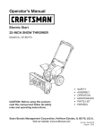
Removecotterpin, wingnut,andhexscrewfrom chutecontrolheadand
clevispinandbow-tiecotterpinfrom chutesupportbracket.SeeFigure2.
Insertchutecontrolrodinto inputof chutecontrolhead.Pushrodasfarinto
the chutecontrolheadaspossible,keepingthe holesin the rodpointing
upward.SeeFigure3.
/ .....
f
j
Rgure3
J
Figure 1
8
4.
Placechuteontochutebaseandensurechutecontrolrodispositionedunder
handlepanel.Installhexbolt previouslyremovedbut donot securewith
wingnut at thistime.SeeFigure4.
5.
Squeeze
the triggeronthe handlepaneljoystickandrotatethe chuteby
handto faceforward.Theholesinthe chutecontrolinputwill befacingup.
SeeFigure5.
TopView
NOTE:Thechutewill not rotatewithoutsqueezingthe triggeronthe joystick.
6.
Rotatethejoysticktothe oneo'clockpositionsothe sliverindicator
arrowon
the inputshaftbelowthe controlpanelpointsupward.SeeFigure6.
NOTE:Thejoystickwill be angledslightlyto the right.SeeFigure5& Figure6.
f
Figure 5
FrontView
Joystick
//f
"_
Figure
4
\
Figure6
9
7.
f
Makesureall cablesareroutedto the left of the chutecontrolrod.Lineup
the holeinthe rodwith the arrowonthe inputshaftandinsertthe rodinto
the inputshaftbelowjoystickon handlepanel.SeeFigure7.
NOTE:
Thechutecontrolrodwill fit snugglyintothe inputshaft.Supportthe
rearofthe dashpanelwith onehandwhileinsertingthe rodwith yourother
handto ensurethe rodisinsertedall the wayinto the inputshaft.
8.
Nowpushthe chutecontrolrodbacktowardsthe handlepaneluntil the
holeinthe rodlinesup with the holeinthe chutecontrolinputclosestto the
chutecontrolhead.Insertthecotter pin.SeeFigure8.
NOTE:
Thesecondholeisusedto achievefurther engagementof the
chutecontrolrodinto the inputshaftif requiredandcanbeusedlater
foradjustmentif the chutedoesnot fully rotate.Referto the Service&
Maintenancesectionfor ChuteControlRodadjustments.
9.
/
Finishsecuringchutecontrolheadto chutesupportbracketwith wing nut,
andclevispinandbow-tiecotter pinremovedearlier.Donot overtighten.
SeeFigure9.
f
Figure8
f
Figure
7
\
Figure9
10
/
Checkthatall cablesareproperlyroutedthroughthe cableguideonthe
engine.SeeFigure10.
/
NOTE:Ifthe chutecontrolisnot assembledcorrectlyit will not movefreely
norwill it movefully to the rightandleft.
;
S
Set-Up
Shear Pins
Holesarelocatedin the plasticdashpanelfor convenientshearpinstorage.See
Figure11.Referto the Operationsectionfor moreinformationregardingshearpin
replacement.
J
Figure
10
f
J
Figure
11
11
ChuteClean-OutTool
_
Achuteclean-outtool isfastenedto the top ofthe augerhousingwith amounting
clip.SeeFigure12.Thetoolisdesignedto clearachuteassemblyof iceand
snow.Thisitemisfastenedwith acabletie at the factory.Cutthe cabletie before
operatingthesnowthrower.
Neveruseyour handsto clearaclogged chuteassembly.Shutoff engine
and remainbehind handlesuntil all movingpartshavestoppedbefore
usingthe clean-outtool to clearthe chuteassembly.
Drift Cutters
1.
Removethe two screwsandwingknobsthatsecureeachdrift cutter,and
removethemfromthe sidesof the augerhousing.
2.
Turnthe drift cuttersaroundandpositionthemasshownin Figure13to the
outsideof the augerhousing.
3.
Attachthe drift cutterswith the screwsandwingknobsremovedearlier.See
Figure14.
J
TirePressure
Figure13
Underany circumstance
do not exceedmanufacturer'srecommendedpsi.
Equaltire pressureshouldbe maintained at all times.Excessivepressure
when seatingbeadsmaycausetirelrim assemblyto burstwith force
sufficient to causeseriousinjury. Referto sidewall of tire for recommended
pressure.
Thetiresareover-inflatedforshippingpurposes.Checkthe tire pressure
before
operatingthesnowthrower.Refertothe tire sidewall for tire manufacturer's
recommended
psianddeflate(orinflate)the tiresasnecessary.
NOTE:Equaltire pressure
isto bemaintainedat all timesforperformancepurposes.
ChuteClean-outTool
Figure14
J
Figure 12
12
Adjustments
f
Skid Shoes
Thesnowthrowerskidshoesareadjustedupwardat the factoryforshipping
purposes.Adjustthemdownward,if desired,priorto operatingthe snowthrower.
Smooth Surface
it is notrecommended
that you operatethis snowthrower on gravelas
it caneasilypickup andthrowloosegravel,causingpersonalinjuryor
damageto the snow thrower andsurroundingproperty.
Forclosesnowremovalon asmoothsurface,raiseskidshoeshigheronthe
augerhousing.Referto Figure15.
Usea middleor lowerpositionwhentheareato beclearedis uneven,suchas
agraveldriveway.
NOTE:Ifyouchooseto operatethe snowthrowerona gravelsurface,keep
the skidshoesinpositionformaximumclearancebetweenthe groundand
the shaveplate.
UnevenSurface
Toadjustthe skidshoes:
1.
J
Loosenthe four hexnuts (two oneachside)andcarriagebolts.Moveskid
shoesto desiredposition. SeeFigure15.
2.
Makecertainthe entirebottomsurfaceof skidshoeisagainstthegroundto
avoidunevenwearon the skidshoes.
3.
Retightennutsandboltssecurely.
Figure15
Auger Control
.....................................................
............................
Priorto operatingyoursnowthrower,carefully readand follow all
instructionsbelow. Performall adjustmentsto verify yoursnowthroweris
operating safelyand properly.
Checkthe adjustmentofthe augercontrolasfollows:
/
1.
Theaugercontrolislocatedon the left handle.SeeFigure16inset.When
the augercontrolisreleasedandinthe disengaged"up"position,the cable
shouldhaveverylittle slack.ItshouldNOTbetight.
/_
2.
Ina well-ventilatedarea,start the snowthrowerengine.Referto Starting
the Engineinthe Operationsection.
3.
Whilestandinginthe operator'sposition(behindthe snowthrower),engage
the auger.
4.
f
/,
Auger Control --
J
\
Allowthe augerto remainengagedfor approximatelyten (10)seconds
beforereleasingthe augercontrol.Repeatthisseveraltimes.
J
Figure16
5.
With theaugercontrolin the disengaged
"up" position,walkto the front of
the machine.
7.
Toreadjustthe controlcable,loosenthe upperhexbolton the augercable
bracket.SeeFigure16.
6.
Confirmthat the augerhascompletelystoppedrotatingandshowsNOsigns
of motion.Ifthe augershowsANYsignsof rotating,immediatelyreturnto
the operator'spositionandshut off the engine.WaitforALLmovingpartsto
stopbeforeadjustingthe augercontrol.
8.
Positionthe bracketupwardto providemoreslack(ordownwardto increase
cabletension).
9.
Retightenthe upperhexbolt.
10.
Repeatsteps2-6aboveto verifyproperadjustmenthasbeenachieved.
13
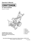
Shift Lever
Drive Control
_
Four-Way
Chute ControP
(Joystick)
Auger Control
Headlight
Gas C_
Wheel Steering Control
Chute Assembly
\
Drift Cutter
Recoil Starter
Handle
Clean Out
Tool
Oil Fill
\
Auger
Hous_
\
Choke
Control
Throttle
Control
Augers
Skid Shoe
Oil Drain
Electric Starter
Outlet
Figure17
Nowthatyouhavesetupyoursnowthrower,it's importantto becomeacquainted
with its controlsandfeatures.Referto Figure17.
6
Shift [ever
,ey
Thekeyisasafetydevice.It mustbefully inserted
in
5
orderfor the enginetostart. Removethe keywhenthe
Theshift leverislocatedonthe right sideof the handlepanel.Placethe shift
leverintoanyof eightpositionsto controlthedirectionof travelandground
speed.Forward
4
NOTE:
Donot turn the
snowthrowerisnot
inignition
use. keyinan attemptto start
the engine.Doingsomaycauseit to break.
Yoursnowthrowerhassixforward(F)speeds.Positionone(1)isthe slowest
andpositionsix(6)isthe fastest.
t2
3
Reverse
activated by turning the rotary choke knob to the CHOKE
position.Activating
the choke controlclosesthe choke
plate on the carburetorand aids instarting the engine.
Yoursnowthrowerhastwo reverse
(R)speeds.One(1)isthe slowerandtwo (2)R 1
isthe faster.
ChokeControl
R2
Drift Cutters
RecoUStarterHandle
Thedrift cuttersaredesignedfor useindeepsnow.Theiruseisoptionalfor normal
snowconditions.Maneuverthe snowthrowersothatthe cutterspenetratea high
standingsnowdrift to assistsnowfallinginto the augersforthrowing.
Thishandleisusedto manuallystartthe engine.
MeetsANSiSafetyStandards
CraftsmanSnowThrowersconformto thesafetystandardof the AmericanNationalStandardsInstitute(ANSI).
14
Ii
(_
O
Throttlecontrol
DriveControl/Auger Control Lock
/
DRIVE
CONTROL
Thethrottlecontrolislocatedonthe rearofthe engine.It regulatesthe speedofthe
engineandwill shutoffthe enginewhen movedinto the STOP
position.
Primer
Depressing
the primerforcesfueldirectlyintothe
engine'scarburetorto aid incold-weatherstarting.
Electric Starter Button
Pressing
the electricstarterbuttonengagesthe engine'selectricstarterwhen
pluggedinto a 120Vpowersource.
Thedrivecontrolislocatedonthe right handle.Squeezethe controlgripagainstthe
handleto engagethe wheeldrive.Release
to stop.
Electric Starter Outlet
Requires
the useof athree-prongoutdoorextensioncordanda 120Vpowersource/
wall outlet.
OilFill
Thedrivecontrolalsolocksthe augercontrolsoyoucanoperatethe chute
directionalcontrolwithoutinterruptingthesnowthrowingprocess.Ifthe auger
controlisengagedsimultaneouslywiththe drivecontrol,the operatorcanrelease
the augercontrol(onthe left handle)andthe augerswill remainengaged.Release
bothcontrolsto stopthe augersandwheeldrive.
flOTE:Alwaysreleasethe drivecontrolbeforechangingspeeds.Failureto dosowill
resultinincreasedwearon yourmachine'sdrivesystem.
Engineoil levelcanbecheckedandoil addedthroughtheoil fill.
GasCap
Four-WayChute Contror M
Unthread
the gascapto addgasolinetothe fuel tank.
CHUTe:
DIRECTIONAL
Auger
CONTROL
CHUTETILT DOWN
t
Whenengaged,the augerbladesrotateanddrawsnowintothe augerhousing.
ChuteAssembly
Snowdrawninto the augerhousingisdischarged
out the chuteassembly.
Skid Shoes
CHUTEROTATE
LEFT
Position
theskidshoes
based
onsurface
conditions.
Adjustupward
forhard-packed
snow.
Adjustdownward
whenoperating
ongravelorcrushed
rocksurfaces.
CHUTETILT UP
_r
AugerControl
CHUTEROTATE
RIGHT
n_
Thefour-waychutecontrol (Joystick)is locatedonthe left sideofthe handle
panel.
TM
f
Tochangethe directioninwhichsnowisthrown,squeeze
the buttonon the
chutecontrolleverandpivotthe chutecontrolleverto the rightor to the
left.
Tochangethe angle/distance
whichsnowisthrown,pivotthe chutecontrol
leverforwardto tilt the chutedownandbackwardto tilt the chuteup.
Wheel Steering Controls
Theleft andright wheelsteeringcontrolsarelocatedon the undersideof the
handles.Squeezethe rightcontrolto turn right;squeezethe left controltoturn left.
NOTE:Operatethe snowthrowerinopenareasuntil youarefamiliarwith these
controls.
Theaugercontrolislocatedon the left handle.Squeeze
the controlgripagainstthe
handleto engagethe augerandstartsnowthrowingaction.Release
to stop.
15
Clean-OutTool
Donot overfill the fueltank.Afterrefueling,makesurethe tankcapisclosed
properlyandsecurely.
Becarefulnot to spillfuelwhen refueling.Spilledfuel orfuel vapormay
ignite.If anyfuel isspilled,makesurethe areaisdry beforestartingthe
engine.
Neveruseyour handsto clearacloggedchuteassembly.Shutoff engine
and remainbehindhandlesuntil all movingparts havestoppedbefore
usingthe clean-outtool to clearthe chuteassembly.
Avoidrepeatedor prolongedcontactwith skinor breathingofvapor.
Thechutedean-outtool isconvenientlyfastenedto the rearofthe augerhousing
with amountingclip.Shouldsnowandicebecomelodgedin thechuteassembly
duringoperation,proceedasfollowsto safelycleanthe chuteassemblyandchute
opening:
Useextreme carewhen handling gasoline.Gasolineis extremely
flammable andthe vaporsareexplosive.Neverfuel the machineindoorsor
while the engine ishotor running. Extinguishcigarettes,cigars,pipes and
othersourcesof ignition.
1.
Release
boththe AugerControlandthe DriveControl.
2.
Stopthe enginebyremovingthe ignitionkey.
3.
Removethe clean-outtool from the clipwhichsecures
it to the rearof the
augerhousing.
4.
Usetheshovel-shaped
endof the clean-outtool to dislodgeandscoopany
snowandicewhichhasformedinandnearthe chuteassembly.
5.
Refasten
the clean-outtool to the mountingdip on the rearof the auger
housing,reinsertthe ignitionkeyandstartthe snowthrower'sengine.
6.
Whilestandinginthe operator'sposition(behindthe snowthrower),engage
the augercontrolforafewsecondstoclearanyremainingsnowandicefrom
the chuteassembly.
1.
Cleanaroundfuelfill beforeremovingcapto fuel.
2.
Afuel levelindicatoris locatedinthe fuel tank.SeeFigure17inset.Be
carefulnotto overfill.Filltank until fuel reachesthe fuellevelindicatorto
allowspacefor fuelexpansion.
Starting The Engine
Alwayskeephandsandfeet clearof moving parts. Donot usea pressurized
starting fluid. Vaporsareflammable.
flOTE:Allowthe engineto warmupfor afewminutesafter starting.Theenginewill
not developfull poweruntil it reachesoperatingtemperatures.
BeforeStarting Engine
Read,understand,andfollow all instructionsandwarnings onthe
machineandin this manualbeforeoperating.
1.
Makecertainboththe augercontrolanddrivecontrolarein thedisengaged
(released)
position.
2.
Insertkeyinto slot.Makesureit snapsinto place.Donot attemptto turn the
key.
NOTE:Theenginecannotstartwithoutthe keyfully insertedinto the
ignitionswitch.
Oil
Theunit wasshippedwith oil inthe engine.Checkoil levelbeforeeachoperationto
ensureadequateoil in the engine.
ElectricStarter
flO?E:Besureto checkthe engineonalevelsurfacewith the enginestopped.
1.
Removethe oil filler cap/dipstickandwipethe dipstickclean.
2.
Insertthe cap/dipstickinto the oil filler neck,but do NOTscrewit in.
3.
Removethe oil filler cap/dipstick.Ifthe levelislow,slowlyaddoil (5W-30,
with aminimumclassification
of SF/SG)
until oil levelregistersbetweenhigh
(H)andlow (L).
Theelectric starter isequippedwith a groundedthree-wire power plug,
andisdesignedto operate on 120voltAChouseholdcurrent. It must be
usedwith a properly groundedthree-prong receptacleat all times to avoid
the possibilityof electrk shock.Follow all instructions
carefully prior to
operatingthe electricstarter. DONOTuseelectric starter in the rain.
flOTE:Donot overfill.Overfillingwith oil mayresultin enginesmoking,hard
startingor sparkplug fouling.
Determinethatyourhome'swring isathree-wiregroundedsystem.Aska licensed
electricianif youarenot certain.
Replace
andtighten cap/dipstickfirmly beforestartingengine.
Ifyouhavea groundedthree-prongreceptacle,proceedasfollows.If youdonot
havethe properhousewiring, DONOTusethe electricstarterunderanyconditions.
4.
Gasoline
Useautomotivegasoline(unleadedor low leadedto minimizecombustionchamber
deposits)witha minimumof87 octane.Gasoline
with up to 10%ethanolor 15%
MTBE(MethylTertiaryButylEther)canbeused.Neveruseanoil/gasolinemixture
or dirty gasoline.Avoidgetting dirt, dust,or waterinthe fuel tank.DONOTuseE85
gasoline.
1.
Pluganextensioncordinto the outletlocatedon the engine'ssurface.Plug
the otherendofextensioncordintoathree-prong120-volt,grounded,AC
outlet inawell-ventilatedarea.
Theextensioncordcan beany length, but must be ratedfor 15ampsat
125volts,groundedand ratedfor outdoor use.
Refuelin awell-ventilatedareawith the enginestopped.Donot smokeor
allowflamesor sparksin the areawherethe engineisrefueledor where
gasolineisstored.
16
2.
ToEngageDrive
Movethrottle controlto FAST
(rabbit)_Jl__ position.
1.
With the
3 Move
choke
tothe
CHOKE
I,'I pos t on
eng
co,d
nestart),fengine
sthrottlecontrolinthe Fast(rabbit)_ _1
into oneof the sixforward(F)positionsor two reverse(R)positions.Selecta
speedappropriatefor thesnowconditionsanda paceyou'recomfortable
with.
warm,placechokein RUNposition.
4.
5.
Pushprimerthree(3)times,makingsureto covervent holeinprimerbulb
whenpushing.Ifengineiswarm,pushprimeronlyonce.Alwayscovervent
holewhenpushing.Coolweathermayrequireprimingto berepeated.
NOTE:Whenselectinga DriveSpeed,usetheslowerspeedsuntilyouare
comfortableandfamiliarwith theoperationof the snowthrower.
Pushstarterbuttonto startengine.Oncethe enginestarts,immediately
releasestarterbutton.Electricstarterisequippedwith thermaloverload
protection;systemwill temporarilyshut-downto allowstarterto coolif
electricstarterbecomes
overloaded.
2.
Squeezethe drivecontrolagainstthe handleandthe snowthrowerwill
move.Release
it anddrivemotionwill stop.
NOTE:NEVER
repositiontheshift lever(changespeedsor directionof travel)
without first releasingthe drivecontrolandbringingthesnowthrowerto a
completestop.Doingsowill resultin prematurewearto the snowthrower'sdrive
system.
Asthe enginewarms,slowlyrotatethe chokecontrolto RUNposition.Ifthe
enginefalters,restartengineandrunwith chokeat half-chokepositionfor a
shortperiodof time,andthenslowlyrotatethe chokeinto RUNposition.
6.
position,moveshift lever
Afterengineisrunning,disconnectpowercordfrom electricstarter.When
disconnecting,
alwaysunplugthe endat the wall outletbeforeunplugging
the oppositeendfrom the engine.
ToEngageAuger
Toengagetheaugerandstartthrowingsnow,squeezethe augercontrol
againstthe left handle.Release
to stopthe auger.
Recoil Starter
ReplacingShearPins
Eachaugerbladeissecuredto the spiralshaftwith ashearpinandbow-tieclip.If
anaugerbladestrikesa foreignobjector icejam, the pinwill shearoff to prevent
damageto the blade.Ifan augerbladedoesnot turn, checkto seeif its pinhas
shearedoff. SeeFigure18.
Donot pull the starter handlewhilethe engine running.
1.
Movethrottle controlto FAST
(rabbit)_ _j position.
2.
Movechoketo the CHOKE
I,.'1
position(coldenginestart).If engineis
warm,placechokein RUNposition.
3.
Pushprimerthree(3)times,makingsureto covervent holewhenpushing.
If engineiswarm,pushprimeronlyonce.Alwayscoverventholewhen
pushing.Coolweathermayrequireprimingto be repeated.
4.
Pullgentlyonthe starterhandleuntil it beginsto resist,then pullquickly
andforcefullyto overcome
the compression.
Donot releasethe handleand
allowit to snapback.ReturnropeSLOWLY
to originalposition.If required,
repeatthisstep.
5.
NEVER
replacethe augershear pinswith anything otherthan SearsSKU#
88389/0EMPart No.738-04124Areplacementshearpins.Any damageto
the augergearboxor other componentsasa result of failing to do sowill
NOTbe coveredbyyour snowthrower's warranty.
Alwaysturn off the snowthrower's engine and removethe keypriorto
replacingshearpins.
Asthe enginewarms,slowlyrotatethe chokecontrolto RUNposition.Ifthe
enginefalters,restartengineandrunwith chokeat half-chokepositionfor a
shortperiodof time,andthenslowlyrotatethe chokeinto RUNposition.
Toavoid unsupervisedengineoperation, never leavethe machine
unattended with the engine running. Turnthe engine off after useand
removekey.
Stopping TheEngine
Afteryouhavefinishedsnow-throwing,runenginefor afewminutesbefore
stoppingto helpdry offany moistureon the engine.
1.
Movethrottle controlto OFFposition.
2.
Removethe key.Removing
the keywill reducethe possibilityof
unauthorizedstartingof the enginewhileequipmentisnot inuse.Keepthe
keyina safeplace.Theenginecannotstartwithout the key.
3.
Wipeanymoistureawayfrom the controlson the engine.
17
Figure18
MAINTENANCE
SCHEDULE
Followthe maintenance
schedulegivenbelow.Thischartdescribes
service
guidelinesonly.Usethe ServiceLogcolumnto keeptrackofcompleted
maintenancetasks.Tolocatethe nearestSearsServiceCenteror to scheduleservice,
Beforeperformingany type of maintenance/service,disengageall controls
andstop the engine.Wait until all moving partshavecometo a complete
stop. Disconnect
sparkplug wire and groundit againstthe engine to
preventunintendedstarting.
simplycontactSearsat 1-800-4-MY-HOME
®.
1.
Engineoil level
1.
Check
2.
Looseor missinghardware
2.
Tightenor replace
3.
Unitandengine.
3.
Clean
Ist 5hours
1.
Engineoil
1.
Change
Annuallyor 25hours
1.
Sparkplug
1.
Check
2.
Controllinkagesandpivots
2.
Lubewith light oil
3.
Wheels
3.
Lubewith multipurposeautogrease
4.
GearshaftandAugershaft
4.
Lubewith light oil
5.
4-WayChuteControl
5.
Checkfor cableslackness
Annuallyor 50hours
1.
Engineoil
1.
Change
Annuallyor 100hours
1.
Sparkplug
1.
Change
BeforeStorage
1.
Fuelsystem
1.
Runengineuntil it stopsfrom lackoffuel
EachUseand every 5 hours
TM
f
GENERAL
RECOMMENDATIONS
CheckingEngine Oil
Beforelubricating, repairing,or inspecting,
disengageall controlsandstop
engine.Wait until all movingparts havecometo acompletestop.
NOTE:Checkthe oil levelbeforeeachuseto besurecorrectoil levelismaintained.
Whenaddingoil to the engine,referto viscositychartbelow.Engineoil capacity
is1100ml(approx.37oz.).Donot over-fill.Usea4-stroke,or anequivalenthigh
detergent,premiumquality motoroil certifiedto meetor exceedU.S.automobile
manufacturer'srequirementsforserviceclassificationSG,SF.Motoroilsclassified
SG,SFwill showthisdesignationon thecontainer.
1.
Removethe oil filler cap/dipstkkandwipethe dipstickclean.
2.
Insertthe cap/dipstickintothe oil filler neck,but do NOTscrewit in.
3.
Removethe oil filler cap/dipstick.Iflevelis low,slowlyaddoil until oil level
registersbetweenhigh(H)andlow (L).SeeFigure19.
4.
J
Figure19
Replace
andtighten cap/dipstickfirmly beforestartingengine.
Tip unitto drainoil intothe container.Usedoil mustbedisposedof at a
propercollectioncenter.
Changing EngineOil
NOTE:Change
the engineoil after the first 5 hoursof operationandoncea season
or every50 hoursthereafter.
1.
Drainfuel fromtank byrunningengineuntil the fueltank isempty.Besure
fuelfill capissecure.
2.
Placesuitableoil collectioncontainerunderoil drainplug.
3.
Removeoil drainplug.SeeFigure20 onnext page.
Usedoil isa hazardouswaste product. Dispose
of usedoil properly. Donot
discardwith householdwaste. Checkwithyour localauthorities or Sears
ServiceCenterfor safedisposal/recyclingfacilities.
5.
18
Reinstallthe drainplugandtighten it securely.
Refillwith the recommended
oil andcheckthe oil level.SeeRecommended
OilUsagechart.Theengine'soil capacityis37ounces.
(oF)-40o-20 o 0o 200 400
(oc)
Oil Drain
-30° -20° -10 ° 0°
Plug
\
DONOTuse nondetergentoil or 2-strokeengine oil. It couldshorten the
engine'sservicelife.
7.
Reinstallthe oil filler cap/dipsticksecurely.
Figure20
E
Thoroughly
washyourhandswith soapandwater assoonaspossibleafter
handling usedoil.
SparkPlug
CheckingSparkPlug
DONOTcheckfor sparkwith sparkplug removed.DONOTcrankenginewith
sparkplug removed.
Ifthe engine hasbeenrunning,the muffler will bevery hot. Becarefulnot
to touchthe muffler.
NOTE:Checkthe sparkplugonceaseasonor every25 hoursof operation.Change
the sparkplugonceaseasonor every100hours.Toensureproperengineoperation,
the sparkplug mustbeproperlygappedandfreeof deposits.
1.
Removethe sparkplugbootandusea sparkplugwrenchto removethe
plug.SeeFigure21.
2.
Visuallyinspectthe sparkplug.Discardthe sparkplugif thereisapparent
wear,or if the insulatoriscrackedor chipped.Cleanthe sparkplugwith a
wirebrushif it isto be reused.
3.
Measurethe pluggapwith afeelergauge.Correctasnecessary
bybending
sideelectrode.SeeFigure22.Thegapshouldbesetto .02-.03inches(0.600.80mm).
4.
Checkthatthe sparkplug washerisin goodconditionandthreadthe spark
plug inbyhandto preventcross-threading.
5.
Afterthe sparkplug isseated,tightenwith asparkplugwrenchto compress
the washer.
SparkPlugBoot
Figure21
Electrode
NOTE:Wheninstallinganewsparkplug,tighten 1/2-turnafterthe sparkplug
seatsto compressthe washer.Whenreinstallinga usedsparkplug,tighten 1/8- to
1/4-turnafter the sparkplugseatsto compressthewasher.
Thesparkplug mustbe tightened securely.Aloosesparkplug can become
very hot andcan damagethe engine.
Figure22
19
Lubrication
"I
GearShaft
Thegear(hex)shaftshouldbelubricatedat leastonceaseasonor after every25
hoursof operation.
I.
Topreventspillage,removeall fuel fromtank byrunningengineuntil it
stops.
2.
Carefullypivotthe snowthrowerupandforwardsothat it restsonthe auger
housing.
3.
Removethe lowerframecoverfrom the undersideof the snowthrowerby
removingthe self-tappingscrewswhichsecureit.
4.
Applya lightcoatingof engineoil (or3-in-1oil) to the hexshaft.SeeFigure
23.
NOTE:
Whenlubricatingthe hexshaft,becarefulnot to get anyoil onthe aluminum
driveplateor rubberfrictionwheel.Doingsowill hinderthe snowthrower'sdrive
system.Wipeoff anyexcessor spilledoil.
Wheels
J
Figure 23
f
Atleastonceaseason,removebothwheels.Cleanandcoattheaxleswitha
multipurposeautomotivegreasebeforereinstallingwheels.
Auger Shaft
Atleastonceaseason,removethe shearpinson augershaft.Spraylubricantinside
shaft,andaroundthe spacers
andflangebearingsfoundat eitherendof the shaft.
SeeFigure24.
ShavePlate and Skid Shoes
Theshaveplateandskidshoeson the bottomofthe snowthroweraresubjectto
wear.Theyshouldbecheckedperiodicallyandreplacedwhennecessary.
flOTE:Theskidshoeson thismachinehavetwo wearedges.Whenonesidewears
out,theycanberotated180°to usethe otheredge.
Toremoveskidshoes:
Remove
thetwocarriage
bolts,washers,
andhexflangenutsthatsecure
eachskidshoetothesnowthrower.
Figure24
2.
Reassemble
newskidshoeswith the fourcarriagebolts(two on eachside),
washers,andhexflangenuts.Referto Figure25.
f
Toremoveshaveplate:
1.
Removethe carriageboltsandhexnutswhichattachit to the snowthrower
housing.
2.
Reassemble
newshaveplate,makingsureheadsof carriageboltsareto the
insideof housing.Tightensecurely.SeeFigure25.
NOTE:Augersnot shown for clarity.
Figure 25
20
f
Adjustments
Shift Cable
If the full rangeof speeds(forwardandreverse)cannotbeachieved,referto the
figureto the fight andadjusttheshift cableasfollows:
I.
Placethe shift leverinthe fastestforwardspeedposition(F6).
2.
Loosenthe hex nut onthe shift cableindexbracket.SeeFigure26.
3.
Pivotthe bracketdownwardtotake upslackinthe cable.
4.
Retightenthe hexnut.
Drive Control
Whenthe drivecontrolis releasedandinthe disengaged
"up" position,the cable
shouldhaveverylittle slack.ItshouldNOTbetight. Also,if thereisexcessive
slack
inthe drivecableor if the unit experiences
intermittentdrivewhileusing,the cable
mayneedto beadjusted.Checkthe adjustmentof the drivecontrolasfollows:
I.
With thedrivecontrolreleased,pushthe snowthrowergentlyforward.The
unit shouldroll freely.
2.
Engagethe drivecontrolandgentlyattemptto pushthe snowthrower
forward.Thewheelsshouldnot turn. Theunit shouldnot roll freely.
3.
With thedrivecontrolreleased,movethe shift leverbackandforth between
Figure26
the R2positionandthe F6positionseveraltimes.Thereshouldbeno
resistanceinthe shift lever.
4.
If anyof the abovetestsfailed,the drivecableisinneedof adjustment.
Proceedasfollows:
a.
Shutoff the engineasinstructedinthe Operationsection.
b.
Loosenthe lowerhexbolt onthe drivecablebracket.SeeFigure27.
c.
Positionthe bracketupwardto providemoreslack(ordownwardto
increasecabletension).
d.
Retightenthe lowerhexbolt.
ChuteControlRod
Toachievemorechutecontrolrodengagementinthe inputshaftunderthe handle
panel,the chutecontrolrodwill haveto beadjusted.Referto Figure28.
Figure27
Toadjustthisrod,proceedasfollows:
I.
Removethe cotterpin fromthe holeclosestto the chutecontrolheadon the
chutecontrolinput.
2.
Pullout the chutecontrolroduntilthe holeinit linesupwith the otherhole
inthe chutecontrolinput.
3.
Relnsertthe cotterpinthroughthisholeandthe chutecontrolrod.
/
i
/
/
/
/
/
/
figure28
21
/
f
Auger
Control
Referto theAssemblysectionforinstructionson adjustingtheaugercontrolcable.
Skid Shoes
Referto theAssemblysectionforinstructionson adjustingtheskidshoes.
8eR Replacement
Auger Belt
Toremoveandreplaceyoursnowthrower'saugerbelt, proceedasfollows:
1.
Topreventspillage,removeall fuel fromtank byrunningengineuntil it
stops.
2.
Removethe plasticbelt coveronthe front of the enginebyremovingthetwo
self-tappingscrews.SeeFigure29.
3.
Rollthe augerbeltoffthe enginepulley.SeeFigure30.
4.
Carefullypivotthe snowthrowerupandforwardsothat it restsonthe auger
housing.
5.
Removethe framecoverfrom the undersideof the snowthrowerby
removingfourself-tappingscrewswhichsecureit. SeeFigure31.
J
Figure29
f
i
Figure30
J
Figure 31
22
.................
Loosenandremovethe shoulderscrewwhichactsasabelt keeper.Referto
Figure32.
Removethe belt fromaroundthe augerpulley,andslipthe belt betweenthe
supportbracketandtheaugerpulley.SeeFigure33.
NOTE:Engagingthe augercontrolwill easeremovalandreinstallationof the
belt.
8.
Reassemble
augerbeltbyfollowing instructionsinreverseorder.
flOTE:DoNOTforgetto reinstallthe shoulderscrewandreconnectthespring
to the frameafterinstallingareplacement
augerbelt.
Performthe AugerControltestoutlinedinthe Assemblysectionof this
manual.
Drive Belt
flOTE:Severalcomponentsmustberemovedandspecialtoolsarerequiredin order
to replacethe snowthrower'sdrivebelt. Contactthe nearestSearsParts& Repair
Centerto havethe drivebelt replaced.
FrictionWheel inspection
Figure32
If the snowthrowerfailsto drivewith the drivecontrolengaged,andperforming
the DriveControlCableAdjustmentfailsto correctthe problem,the frictionwheel
mayneedto bereplaced.Examinethe frictionwheelrubberforsignsof wearor
crackingandreplacewheelif necessary.
flOTE:Severalcomponentsmustberemovedandspecialtoolsarerequiredin order
to replacethissnowthrower'sfrictionwheel.Ifyourfrictionwheelneedsto be
replaced,contactthe nearestSearsParts& RepairCenter.
Toinspectthe frictionwheel,proceedasfollows:
1.
Allowthe engineto rununtil it isout of fuel. Donot attemptto pourfuel
fromthe engine.
2.
Carefullypivotthe snowthrowerupandforwardsothat it restson theauger
housing.
3.
Removethe framecoverfrom the undersideof the snowthrowerby
removingfourself-tappingscrewswhichsecureit. Referto Figure31.
4.
Examinethe frictionwheelforsignsof wearor cracking.
i
:_
Figure33
23
•
/
If the snowthrowerwill not beusedfor 30daysor longer,or if it is theendof thesnowseasonwhenthe lastpossibilityof snowisgone,the equipmentneedsto bestored
properly.Followstorageinstructionsbelowto ensuretop performancefrom thesnowthrowerformanymoreyears.
PreparingEngine
PreparingSnowThrower
Enginesstoredover30daysneedto bedrainedof fuel to preventdeteriorationand
gumfromforminginfuel systemor on essentialcarburetorparts.If thegasolinein
yourenginedeterioratesduringstorage,youmayneedto havethe carburetor,and
otherfuel systemcomponents,servicedor replaced.
Whenstoringthe snowthrowerin anunventilatedor metalstorageshed,
careshouldbetakento rustproofthe equipment.Usinga lightoil or silicone,
coatthe equipment,especially
anychains,springs,bearingsandcables.
1.
Removeall fuel fromtank byrunningengineuntil it stops.Donot attemptto
pourfuelfrom the engine.
Followlubricationrecommendations.
2.
Changetheengineoil.
3.
Removesparkplugandpourapproximately1oz.(30ml) ofcleanengineoil
into the cylinder.Pullthe recoilstarterseveraltimesto distributetheoil, and
reinstallthe sparkplug.
4.
Cleandebrisfrom aroundengine,andunder,around,andbehindmuffler.
Applya lightfilm ofoil on anyareasthat aresusceptibleto rust.
Removeall dirt fromexteriorof engineandequipment.
Storeequipmentinaclean,dry area.
Inflatethe tiresto the maximumPSI.Referto tire sidewall.
Storeinaclean,dry andwell ventilatedareaawayfromanyappliancethat
operateswith aflameor pilot light,suchasa furnace,waterheater,or
clothesdryer.Avoidanyareawitha sparkproducingelectricmotor,or where
powertoolsareoperated.
Neverstore snowthrower with fuel in tank indoorsor in poorlyventilated
areas,where fuel fumes may reachan openflame, sparkor pilotlight ason
a furnace,water heater,clothesdryeror gasappliance.
If possible,avoidstorageareaswith high humidity.
Keepthe enginelevelinstorage.Tiltingcancausefuelor oil leakage.
24
25
Disconnect
the sparkplug wireandgroundit againstthe engine to prevent
unintendedstarting. Beforeperforminganytypeof maintenance/service,
disengageall controls andstop the engine.Wait until aHmovingparts
havecometo a completestop.Alwayswear safetyglassesduringoperation
or while performingany adjustmentsor repairs.
Thissection
addresses
minorservice
issues.
Tolocatethe nearestSearsServiceCenterorto schedule
service,
simplycontactSearsat 1-800-4-MY=HOMP.
Engine fails to start
1. Choke control not in CHOKE position.
1. Move choke control to CHOKE position.
2. Spark plug wire disconnected.
2. Connectwire
3. Faulty spark plug.
3. Clean, adjust gap, or replace.
4. Fuel tank empty or stale fuel.
4. Fill tank with clean, fresh gasoline.
5. Engine not primed.
5. Prime engine as instructed
6. Key not inserted.
6. Insert key fully into the switch.
7. Extension
cord not connected
(when
Engine running
erratically/
RPM (hunting
1. Engine running
on CHOKE.
in the Operation
7. Connect one end of the extension
Section.
cord to the
electric starter outlet and the other end to a threeprong 120-volt, grounded, AC outlet.
using electric start button, on models so
equipped).
inconsistent
to spark plug.
1. Move choke control to RUN position.
2. Stale fuel.
2. Fill tank with clean, fresh gasoline.
3. Water or dirt in fuel system.
3. Drain fuel tank by running
with fresh fuel.
4. Carburetor
4.
or surging)
out of adjustment.
5. Over-governed
engine until it stops. Refill
Contact your Sears Parts & Repair Center.
5. Contact your Sears Parts & Repair Center.
engine.
Excessive vibration
1. Loose parts or damaged
Lossof power
1. Spark plug wire loose.
1.
2. Gas cap vent hole plugged.
2. Remove ice and snow from gas cap. Be certain vent
hole is clear.
1. Drive cable in need of adjustment.
1. Adjust drive control cable. Refer to Service and
Maintenance section.
2. Drive belt loose or damaged.
2. Have drive belt replaced. Contact your Sears Parts &
Repair Center.
3. Worn friction
3. Have friction wheel replaced at a Sears Parts &
Repair Center.
Unit fails to propel itself
1. Stop engine immediately
and disconnect spark
plug wire. Tighten all bolts and nuts. If vibration
continues, have unit serviced by a Sears Parts &
Repair Center.
auger.
wheel.
NEED MORE HELP?
Find this
and a[[ your
Get answers
from
other
our team
product
manuals
of home
experts.
online,
Get a personalized maintenance plan for your home.
Find information and tools to help Mth home projects.
26
Connect and tighten
spark plug wire.
Unit fails to discharge snow
1. Chute assembly
clogged.
2. Foreign object lodged
Chute fails to easily rotate
180 degrees
1. Stop engine immediately and disconnect spark
plug wire. Clean chute assembly and inside of auger
housing with clean-out tool or a stick.
in auger.
2. Stop engine immediately and disconnect spark plug
wire. Remove object from auger with clean-out tool
or a stick.
3. Auger cable in need of adjustment.
3. Adjust auger control cable. Refer to Assembly
section.
4. Auger belt loose or damaged.
4. Replace auger belt. Refer to Service and
Maintenance section.
5. Shearpin(s) sheared.
5. Replace with new shear pin(s).
1. Chute assembled incorrectly.
1. Disassemble
directed
NEED MORE HELP?
YotJU,fir_} the _: swe a_] :m,_"
Yeo_:__._a_,a_emy[f_eo_@_,,,,,,,
fo_' free!
o Find this
and a[[ your
Get answers
from
other
our team
product
manuals
of home
experts,
online.
o Get a personalized maintenance plan for your home_
Find information
and tools to help with home projects.
27
chute control and reassemble
in the Assembly
section.
as
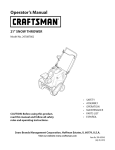
Craftsman SnowThrower Model 247.883951
18
13
28
54
7
31
--48
39
31
i27
39/ _(
28
Craftsman SnowThrower Model 247.883951
m
M
1.
731-2635
Snow Removal Tool Mount
29.
684-04107-4044
Spiral Assembly,
LH
2.
684-04057A-0637
Impeller
12" Dia.
30.
684-04108-4044
Spiral Assembly,
RH
731-04870
Spacer, 1.25 OD x .75 ID x 1.00
Assembly,
3.
710-0347
Hex Screw, 3/8-16, 1.75, Gr5
31.
4.
710-0451
Bolt, Carriage,
32.
736-0188
Washer, Flat, .76 x 1.49 x .06
5.
710-04484
Screw, 5/16-18, 0.750
33.
741-0493A
Bushing, Flange, .80 ID x .91 OD
Screw, Carriage,
34.
790-00087A-0637
Housing,
790-00118-0691
Shave Plate, 2.25 x 27.66
5/16-18, .750 Grl
6.
710-0703
7.
712-04063
Nut, Flange Lock, 5/16-18, Nylon
35.
8.
712-04064
Nut, Flange Lock, 1/4-20, Nylon
36.
731-05984A
Slide Shoe
918-0123A
1/4-20, .750, Gr5
1" Hex Bearing
9.
712-04065
Nut, Flange Lock, 3/8-16, Nylon
37.
Housing,
Auger, RH Reduced
10.
714-04040
Cotter Pin, Bow-tie
38.
918-0124A
Housing,
Auger, LH Reduced
11.
936-0159
Washer, Flat, .349 x .879 x .063
39.
921-0338
Seal, Oil, .750 x 1.00 x .125
Nut, Push-on, .25 Dia
40.
741-0662
Bearing, Flange, .75 x 1.0 x .59
41.
710-0642
Screw, Self-tapping,
12.
926-04012
1/4-20, 0.750
13.
731-07525
Chute, Adapter
14.
732-04460
Spring, Extension,
.38 OD x 4.59
42.
711-04283
Axle, Auger, 28"
15.
736-0174
Washer, Wave, .625 x .885 x .015
43.
914-0161
Key, Hi-pro 3/16 x 5/8
715-04021
Pin, Dowel, .25 OD x 1.2
5" Dia
16.
736-0242
Washer, Bell, .340 x .872 x .060
44.
17.
946-04230A
Clutch
45.
917-04126
Shaft, Worm .75 OD
18.
931-2643
Snow Removal Tool
46.
917-04861
Gear, Worm 20T
718-04071
Collar, Thrust
Cable, Auger, 47.23"
19.
738-0143
Screw, Shoulder,
.498 x .34, 3/8-16
47.
20.
938-0281
Screw, Shoulder,
.625 x .17, 3/8-16
48.
721-0325
Plug, 1/4 x .437
21.
738-04124A
Shear Pin, .25 x 1.50
49.
721-0327
Seal, Oil, .75 x 1 x .131
936-0351
Washer, Flat, .760 ID x 1.50D
22.
941-0245
Bearing, Hex Flange x .75 ID
50.
23.
941-0309
Bearing, Ball, .75 ID x 1.85 OD
51.
736-3084
Washer, Flat, .51 x 1.12
24.
756-04224
Flat Pulley, Idler, 2.75 OD
52.
741-0663
Bearing, Flange, .75 x 1.0 x .925
Housing,
53.
741-0661 B
Bearing, Flange, .75 x 1.00 x .975
710-0276
Screw, Carriage, 5/16-18 x 1.00
25.
790-00075
26.
790-00080A-0637
Bracket, Auger Idler w/Brake
54.
27.
918-04173A
Gearbox
Auger, 28"
55.
920-0284
Wing
Auger 28"
56.
790-00181-0691
Drift Cutter
28.
684-04268-0691
Housing
Bearing, 1.85 ID
Assembly,
Assembly,
29
Knob
Craftsman SnowThrower Model 247.883951
27
/
27
!
/
/
/
3O
/
s!
Craftsman SnowThrower Model 247.883951
M
1.
984-04338A
4-Way Chute Control
2.
710-04187
Hi-Lo Screw, 1/4-15 x 0.5
3.
715-0150
Roll Pin
4.
747-05116
Chute Rod
5.
710-04370
Hex Screw, 1/4-20 x 3.00
6.
738-04367
Flange Shoulder
i
918-04801A
4-Way Chute Gearbox
8.
736-04446
Flat Washer, .25 x .630 x .0515
9.
920-0284
Wing Knob
10.
936-0159
Flat Washer, .349 x .879 x .063
11.
731-04427A
Upper Chute
12.
914-0101
Cotter Pin
13.
711-04469A
Clevis Pin
14.
712-3087
Wing Nut, 1/4-20
15.
684-04310A-0637
Chute Support
16.
714-04040
Bow Tie Cotter Pin
17.
712-04064
Flange Lock Nut, 1/4-20
18.
712-04063
Flange Lock Nut, 5/16-18
19.
784-5594-0637
Cable Bracket
20.
731-06451
Chute Tilt Cable Guide
21.
710-0262
Carriage
22.
710-0895
Hi-Lo Screw, 1/4-15 x .75
23.
710-04071
Carriage
24.
731-06440A
Lower Chute
25.
710-0627
Hex Screw, 5/16-24 x .750
26.
946-04528A
4-Way Cable
946-04477
4-Way Cable w/Clip (Not Shown)
27.
753-06151
Handle Assembly
28.
731-04893A
Handle Plunger
29.
710-04879
Screw, Mach., #8-32 x .750
30.
710-04353
Screw, #8 x 1.00
31.
731-07031
Handle Lever
32.
984-04324A
Shift Assembly
33.
753-06152
Gear Set Assembly
34.
753-06153
Handle Housing
35.
710-1256
Screw, #8-18 x 1.250
36.
684-04350
Joint Block Assembly
37.
715-04095
Pin
753-08018±
Chute Kit (Incl. Ref.# 11 & 24)
Available
for warranty
service provider
coverage
31
Screw
Assembly
Bracket
Bolt, 5/16-18 x 1.50
Bolt, 5/16-18 x 1.0
only. Contact
for details.
Assembly
TM
Assembly
a Sears authorized
Craftsman SnowThrower Model 247.883951
2
3
12
/
31
45
61.-'_
32
Craftsman SnowThrowerModel 247.883951
m
m
I.
684-o4112c
Handle Engagement
37.
749-04191A-0637
Upper Handle LH
2.
732-04238
3.
731-04894D
Torsion Spring
38.
710-04326
Screw, #8-16 x 0.50
Lock Plate
4.
39.
732-04219C
Clutch Lock Spring
684-04250
Pivot Rod
40.
738-04126
Pin, 3/16
Ass'y RH
5.
935-0199A
Rubber Bumper
41.
716-04036
Retainer
6.
710-3069
Screw, 1/4-20 x .500
42.
925-06095
Headlight
7.
731-04896B
Clutch
43.
710-I 652
AB Screw, 1/4-20 x 0.625
8.
712-04081A
Shoulder
44.
731-06401
Belt Cover
9.
684- 04111 B
Handle Engagement
45.
926-04012
Push-on
1o.
631-04133A
Handle Clutch
46.
756- 04109
Auger Pulley
11.
720-0274
Handle Grip
47.
736-0505
Flat Washer
12.
710-1233
Screw, #10-24 x 0.375
48.
738-04439
Shoulder
13.
738-04348
Shoulder
49.
936-0119
Lock Washer
14.
710-04586
Screw, 1/4-20 x 1.625
50.
684-04169
Idler Pulley Assembly
15.
749-04190A-0637
Upper Handle RH
51.
790-00332-0637
Pit., Cvr.
16.
710-0572
Carriage
52.
750-04571
Spacer
17.
720-04039
Shift Knob
53.
732-04308A
Torsion Spring
18.
753-06437
Handle Panel
54.
710-0672
Hex Screw, 5/16-24 x 1.25
19.
731-05324
Lens
55.
756-04252
Pulley Half
20.
731-06113
Steering
56.
954-04201A
Belt, Wheel
21.
631-04134B
Handle Clutch
57.
710-0809
TT Screw, 1/4-20 x 1.25
22.
926-0154
Ca ble Tie
58.
790-00208D
Drive Clutch Idler Bracket
23.
712-04064
Flange Lock Nut, 1/4-20
59.
748-04112B
Shoulder
24.
732-0193
Compression
60.
750-04477A
Spacer
25.
790-00311B-0637
Shift Lever
61.
710-0654A
TT Seres Screw, 3/8-16 x 1.0
26.
790-00248C-0637
Panel Bracket
62.
750-04303
Spacer
27.
738-04125
Shoulder
63.
756- 04113
Pulley Half
28.
920-0284
Wing Knob
64.
736-3082A
Flat Washer
29.
946-04396A
Speed Selector
65.
710-0191
Hex Bolt, 3/8-24 x 1.25
30.
936-0267
Flat Washer
66.
748-04053A
Pulley Adapter
31.
914-0145
Click Pin
67.
710-1245B
Hex Bolt, 5/16-24 x 0.875
32.
749-04138B-0637
Lower Handle
68.
954- 04195A
V-Belt,.500
33.
710-04484
Screw, 5/16-18 x 0.75
69.
936-0329
Lock Washer
34.
710-04022
Screw, M8-1.25
N/A
35.
936-0264
Flat Washer, .330 x .630 x .0635
36.
732-04677
Cable Control
Lock Cam
Nut, 1/4-20
Assembly
LH
Lock LH Assembly
Screw, 1/4-20
Screw, 5/16-18 x 2.25
Control
Lock RH Assembly
Spring
Screw
Cable
Ring
Socket
Nut
Screw
Drive
Spacer
x 35.00 Lg
Engine (see breakdown)
MTD Model No. 952Z270-SUA
725-05147
Wire
33
Light Harness (Not Shown)
Craftsman
Snow
Thrower
Model
247.883951
42
2
I
14 l
13
10
20
20
I
36
22
26
45
24
I
28
57
62
58
34
Craftsman SnowThrower Model 247.883951
m
m
1.
735-04099
Plug, 3/8 ID
32.
738-04184A
Shoulder
2.
711-1268B
Actuator
33.
790-00316-0691
Frame Cover
Shaft
Screw
3.
946-05067
Drive Clutch Cable
34.
656-04055
Friction
4.
732-04345
Extension
35.
918-06072
Drive Shaft Assembly
5.
790-00207C
Drive Clutch Cable Guide Bracket
36.
684-04153C
Friction
6.
684-04156A
Shift Rod Assembly
37.
716-0136
Retainer
7.
750-04474
Axle Support
38.
726-0221
Speed Nut
8.
914-0126
Hi Pro Key
39.
790-00183C-0691
Wheel Drive Frame
9.
735-04100
Plug, 1/2 ID
40.
932-0264
Extension
712-0417A
Flange Nut, 5/8-18
Spring
Tube
Wheel
Disc Assembly
Wheel Assembly
Ring
Spring
10.
917-04210
Gear, 56T
41.
11.
941-0245
Hex Flange Bearing
42.
946-0956C
Steering Cable
12.
790-00206A-0637
Auger Clutch Cable Guide Bracket
43.
790-00528-0691
Shaft Retainer-
750-0767
Axle Spacer
RH
13.
756-0625
Cable Roller
44.
14.
738-0924A
C Screw, 1/4-28 x 0.375
45.
712-04065
Flange Lock Nut, 3/8-16
15.
618-06988
Dogg Assembly
- LH
46.
710-0751
Hex Screw, 1/4-20 x .620
- RH
47.
790-00217A-0637
Speed Selector
Pivot Bracket
790-00218A-0637
Speed Selector
Shift Bracket
618-06987
Dogg Assembly
16.
936-3015
Washer, Flat
48.
17.
732-04311A
Torsion Spring, .750 ID x .968 Lg.
49.
712-04063
Flange Lock Nut, 5/16-18
18.
731-05297
Spacer
50.
712-04064
Flange Lock Nut, 1/4-20
19.
916-0104
E Ring
51.
618-0063A
Friction
Wheel
20.
736-0188
Flat Washer, .76 x 1.49 x .06
52.
935-04054
Friction
Wheel
21.
750-06087
Spacer
53.
790-00174C
Friction
Plate
22.
941-0563
Ball Bearing
54.
710-04484
Screw, 5/16-18 x .750
23.
938-04180
Axle
55.
710-1652
AB Screw, 1/4-20 x 0.625
24.
731-04873
Spacer
56.
918-06054
Gear Assembly,
918-06056
Carrier Assembly,
Bearing Assembly
Plantry Ring
25.
710-0788
TT Screw, 1/4-20 x 1.0
57.
26.
790-00527-0691
Shaft Retainer-
58.
711-06117
Shaft, Strbl Drv Hex, .812
27.
634-04145-0911
Wheel Complete
- LH
59.
916-0231
E-Ring
- RH
60.
717-05146
Gear, Sun, 18T
61.
717-1209A
Gear, 12T
62.
736-04581
Washer, Thrust, .75 x 1.25 x .03
63.
736-05031
Washer, Flat, .67 x 1.174 x .02
634-04146-0911
Wheel Complete
LH
28.
710-05339
Screw, 5/16-24 x 0.75
29.
684-04154B-0637
Friction
Wheel Support
Brkt. Assy.
30.
790-00096A-0637
Auger Cable Guide Bracket
31.
748-0190
Spacer
35
Plantry
Ring
Craftsman
Engine
Model478-SUBForSnowModel 247.883951
D _
o
1
710-04915
Bolt, M6x12
2
951-11194
Muffler
3
710-04915
Bolt M6x12
4
951-10757
Throttle
Control
5
951-11594
Control
Panel
7
731-05632
Key
8
951-10637
Key Switch Assembly
9
951-11302
Choke Knob
10
710-04914
Bolt M6xlO
11
951-11181
Exhaust Pipe Shield
12
951-11227
Carb Isolator
13
710-04968
Bolt M6x16
14
951-11195
Muffler
15
712-05015
Nut, M8
36
Shield
Knob
Bracket
Assembly
0
Craftsman Engine Model 478-SUBForSnow Model 247.883951
133-9
h
i
O
P
m
o1139
13o7o 140--_
145- Carburetor Kit
D
-
129
710-04963
Stud M6-8x10⁴
130
951-11225
Carburetor
Insulator
131
951-11222
Carburetor
Insulator
132
951-11223
Carburetor
Gasket
o
140_
0
D -
Gasket
I
n_
Idle Jet Rivet
J
n_
Idle Jet Assembly
k
n_
Idle Speed Adjusting
I
n_
Primer Pipe
m
751-11991
Primer Hose
133
951-14024A
Carburetor
134
951-10639A
Primer Assembly
n
951-11906
Hose Clamp
135
951-11824
Primer
O
n/a
Carburetor
137
951-11190
Heater Box
P
n/a
Float Pin
138
951-11192
Choke Control
q
n/a
Emulsion
139
736-04477
LockWasher
r
n/a
Needle Valve
140
712-05015
NutM6
s
n/a
Main Jet
145
951-12762A
Carburetor
t
n/a
Needle Valve Spring
a
n/a
Choke Shaft
U
n/a
Float
b
736-04638
LockWasher
V
951-11970
Fuel Bowl Gasket
C
710-05469
Screw M3x6
W
n/a
Fuel Bowl
d
n/a
Choke Plate
X
951-11348
Fuel Bowl Gasket
e
Assembly
Kit (Incl. ij,p,q,r,s,t,u,v,x,z)
o
o
Screw
Body
Tube
n/a
Throttle
Shaft
Y
710-04945
Fuel Bowl Mounting
f
n/a
Throttle
Plate
Z
951-11349
Fuel Drain Plug Gasket
g
n/a
Gasket
aa
710-04938
Fuel Drain Plug
h
n/a
Throttle
Shaft Cover
37
Bolt
Craftsman Engine Model478-SUBForSnowModel 247.883951
142- Gasket Kit- Complete
61
144- Complete Engine
68
418
42
38
Craftsman Engine Model 478-SUBForSnow Model 247.883951
ID _
o
m
o
ID _
66
710-04971
Bolt M8x38
Piston
67
710-04972
Bolt M8x45
Piston Pin Snap Ring
68
710-05052
Bolt M8x35
951-12044
Piston Pin
69
710-04968
Bolt M6x16
951-12387
Piston Ring Set
70
951-11320
Dipstick
71
710-05349
Bolt M6x8
4O
951-12066
Connecting
41
951-12043
42
951 -I 1632
43
44
Rod Assembly
751-12068
Governor
49
951-12069
Radial Ball Bearing
73
951-11904
Oil Fill Tube O-Ring
5O
736-04453
Washer 8x20xO.8
74
951-12073
Oil Fill Tube Assembly
75
951-11381
Assembly
51
714-04077
Cotter Pin
Dipstick
O-Ring
52
951 -I 1958
Governor
Seal
76
951-11971A
Dipstick
Assembly
53
951-12071
Governor
Arm Shaft
77
951-11230
Crankcase
951-11187
Short Block Assembly
54
951-11229
Crankshaft
55
951-10307
Woodruff
56
715-04102
Dowel
Pin 9x12
57
715-04092
Dowel
Pin 7x14
58
951-12072
Camshaft
59
951 -I 1374
6O
736-04545
61
951-11283
62
951-11577
O-Ring
64
951-12395
Crankcase Cover
64
951-11228
Crankcase Cover Kit
Kit (Incl. 49,54,55,65,81)
951-11372
Kit (Incl. 49,52,77,81)
(Incl. 40-44,48-68,77-81,103,
Key
106,107,109,111,124,130-132)
78
951-11350
Oil Drain Pipe
79
736-04440
Washer lOx16x1.5
Crankcase Cover Gasket
80
710-04906
Oil Drain Plug
Washer 16x24xO.5
81
751-11498
Oil Seal 30x46x8
Oil Fill Plug Assembly
142
951-11209
Gasket Kit - Complete
Assembly
(Incl. 52,59,65,79,
81,107,109,124,130-132)
143
951-11210
144
952Z478-SUB
Gasket Kit - External
(I n cl. 79,109,124,130-132)
(Incl. 49,59,50,64-68)
65
o
Clamp
48
Gear/Shaft
o
Oil Seal, 30x46x8
39
Complete
Engine
Craftsman Engine Model478-SUBForSnowModel 247.883951
123
123
142- GasketKit- Complete
143- 6asker Kit- External
4O
144- Complete Engine
Craftsman Engine Mode[ 478-SUBForSnow Mode[ 247.883951
n
D
_
o
o
101
951-11198
Valve Kit
103
951-11962
Tappet
104
951-11199
Push Rod Kit
105
951-11226
Cylinder
Head Kit (Inc1.107,111,112,125)
951-11188
Cylinder
Head Assembly
106
715-04097
Dowel
107
951-12076
Gasket, Cylinder
108
951-10292
Spark Plug/F6Rtc
109
951-11212
Exhaust Pipe Gasket
110
710-04964
Stud M8x48.5
110
951-11207
Muffler
111
710-04965
Bolt M10x1.25x80
112
951-11964
Valve Seal (Intake)
113
951-12077
Valve Spring Retainer(Intake)
114
951-12078
Valve Spring
115
951-12080
Valve Spring Retainer
116
951-12081
Exhaust Lash Cap
117
951-11965
Push Rod Guide
118
951-11981
Rocker Arm Assembly
119
710-04962
Bolt, Pivot
120
951-11966
Rocker Arm
121
751-11123
Adjusting
122
751-11124
Nut, Pivot Locking
123
710-05054
Valve Cover Bolt
124
951-11967
Valve Cover Gasket
125
951-11220
Valve Cover
126a
731-07059
Breather
Hose
126b
726-04101
Breather
Hose Clamp
127
951-11180
Air Shield
128
710-04915
Bolt M6x12
141
951-11333
Valve Cover Kit
142
951-11209
Gasket Kit- Complete
143
951-11210
(Inc1.101,102,
105,107, 109-122,124,129-132)
Pin 12x20
Head
Stud Assembly
Nut ,Valve
(Incl. 52,59,65,
79,81,107, 109,124,130-132)
Gasket Kit- External
(I n cl. 79,109,124,130-132)
144
952Z478-SUB
Complete
41
Engine
Craftsman Engine Model478-SUBForSnowModel 247.883951
46
91
94
96
94
9O
P
_'-99
D
-
o
o
D-
oo
45
710-04965
Bolt M4x55
90
951-11217
Cooling
46
951-11196
Electric Starter
91
951-11218
Starter Cup
47
710-04967
Bolt M8x55
92
712-04220
Nut, Special, M16x1.5
82
951-11498
Ignition
Coil Assembly
93
710-04968
Bolt M6x16
83
951-11197
Ignition
Coil Bolt
94
710-04915
Bolt M6x12
85
951-12553
Alternator
96
951-11379
Blower
86
710-04969
Bolt M6x30
97
951-11208
Recoil Starter
736-04455
Gasket 6
710-04974
Bolt M6xlO
Assembly
87
710-04966
Bolt M6x8
98
88
951-II186
Wire Plate
99
89
951-12090
Flywheel
42
Fan
Housing
Craftsman Engine Model 478-SUBForSnow Model 247.883951
25
3A 32
D _
o
o
ID -
16
951-12533
Fuel Cap Assembly
28
951-11700
Fuel Hose Clamp
17
951-11933
Fuel Level Indicator
29
710-04921
Bolt M8x14
18
710-04970
Bolt M8x20
30
951-11182
Gas Tank Support
o
Bracket
19
750-05312
Bushing
32
712-04212
Nut M6
20
750-05313
Bushing
33
710-04908
Governor
Arm Bolt
21
951-11201
Fuel Tank Assembly
34
951-11231
Governor
Arm
22
951-11184
Governor
35
951-11202
Governor
Spring
36
951-11203
Throttle
Linkage Spring
37
951-11204
Throttle
Linkage
Cover
23
951-11183
Rear Mainting
24
951-12385
Decorate
25
710-04968
Bolt M6x16
38
951-11213
Primer Bracket
39
710-04915
Bolt, M6x12
Bracket Assy.
Cover
26
736-04452
Bush
27
951-11200
Fuel Line Kit
43
o
Craftsman SnowThrower ModeJ247.883951
777S32636
•
--
" _
1001 LflO-NV]lO
"IVflNVW
•
S,UO/VU3dO QV3U "G
"S30V_UflS 13AV_O NO9NI/VU3dO
N3HM NOIlflVO VULX33$fl "S930NVIS19 LV 399VHOSIQ
10391093A]N 'S31HflrNI S103r80 NMOUHI OIOAV Ol "_
'3NIHOVVJ ONIOIAH3S HO ONIOOO1ONfl
390J38 03ddOIS 3AVH 81_JVdONIAOI_ IIV IIINNS310NVH
QNIH38 NIVW3H ONV ']NION3 dOIS '893A31 901nlo 30VON3810"_
"31fiND ]9UVHOSIO OOlONfl Ol lOOl lflO-NV]19
3Sfl "Z
"133d ONVSONVH31VlfldWV NVO 930flV 90 9Bll3dWI HIlM
lOVlNOO "B]gflV ONVU3113dWI 9NllVlOU WOBd AVAAVd33H "L
777S32236
777122339
777D16338
STARTING
INSTRUCTIONS:
777D19073
777122363
777D16340
777X43688
777122340
/ CONTAINING
MORE
THAN 10% ETHANOL
777D18035
44
FEDERAL
and/or CALIFORNIA
EMISSIONCONTROL
WARRANTYSTATEMENT
YOURWARRANTYRIGHTSANDOBLIGATIONS
MTD Consumer Group Inc, the United States Environmental
Protection Agency (EPA), and for those products
California, the California Air Resources Board (CARB) are pleased to explain the emission (evaporative and/or
warranty
on your 2013 and later small off-road
spark-ignited
engine and equipment
(outdoor
equipment
engines
must be designed,
built and equipped
to meet the State's stringent
equipment
engines
must be designed,
built, and equipped
to meet the U.S. EPA small off-road
equipment
anti-smog
certified
exhaust)
engine).
standards
engine
diagnosis,
condition
exists, MTD Consumer
Group Inc will repair your outdoor
equipment
new outdoor
regulations).
of time listed below, provided
Your ECS may include parts such as the carburetor, fuel-injection
system, ignition system, catalytic converter,
valves, canisters, filters, vapor hoses, clamps, connectors,
and other associated emission-related
components.
Where a warrantable
In California,
(in other states, outdoor
spark ignition
Consumer Group Inc must warrant the ECSon your outdoor equipment
engine for the period
abuse, neglect, or improper maintenance
of the outdoor equipment
engine.
for sale in the state of
control system (ECS)
MTD
there has been no
fuel tanks, fuel lines, fuel caps,
engine at no cost to you including
parts, and labor.
MANUFACTURER'S
WARRANTYCOVERAGE:
This emission
control system is warranted
for two years. If any emission-related
part on your outdoor
part will be repaired or replaced by MTD Consumer Group Inc. In the event that a component
Manufacturer's
equipment warranty, the longer coverage period will apply.
equipment
is covered
engine
for longer
is defective,
the
than two years by the
/
OWNERSWARRANTY
RESPONSIBILITIES:
As the outdoor equipment
engine
Consumer Group Inc recommends
Group Inc cannot deny warranty
As the outdoor
your outdoor
equipment
equipment
owner, you are responsible
that you retain all receipts
for performance
of the required maintenance
listed in your owner's manual. MTD
covering maintenance
on your outdoor equipment
engine, but MTD Consumer
solely for the lack of receipts.
engine
owner, you should
however
be aware that MTD Consumer
engine or a part has failed due to abuse, neglect,
improper
Group Inc may deny you warranty
maintenance,
or unapproved
coverage
if
modifications.
You are responsible for presenting your outdoor equipment
engine to MTD Consumer Group Inc's distribution
center or service center as soon
as the problem exists. The warranty repairs should be completed
in a reasonable amount of time, not to exceed 30 days. If you have a question
regarding
http://su
your warranty
pport.mtd
coverage,
you should contact
the MTD Consumer
Group Inc Service Department
at 1-800-800-7310
or at
prod ucts.com.
GENERALEMISSIONS
WARRANTYCOVERAGE:
MTD Consumer
designed,
Group Inc warrants
built, and equipped
cause the failure of a warranted
The warranty
period
Subject to certain
1.
to the ultimate
so as to conform
part for a period
Any warranted
and exclusions
regulations;
equipment
Group Inc according
remainder
of the period.
for replacement
to subsection
as required
Any warranted
part that is scheduled
stated above. Any such part repaired
only for regular inspection
or replaced under warranty
3.
Any warranted
for replacement
part that is scheduled
replacement
as required
to an ultimate
maintenance
(4) below. Any such part repaired
2.
of time before the first scheduled
that the outdoor
on emission-related
stated above. If the part fails during the period of warranty
Consumer
period
purchaser
and (2) free from defects
engine is delivered
as stated below, the warranty
part that is not scheduled
period
and each subsequent
equipment
in materials
engine
is: (1)
and workmanship
purchaser
or first placed into service.
parts is as follows:
in the written
coverage,
instructions
supplied
the part will be repaired
or replaced
under warranty
is warranted
or replaced
will be warranted
for the
in the written instructions
supplied is warranted for the warranty
will be warranted for the remaining warranty period.
maintenance
in the written
instructions
supplied
date for that part. If the part fails before the first scheduled
Repair or replacement
to the owner.
5.
Notwithstanding
of any warranted
the provisions
service the subject engines
6.
The outdoor
equipment
emission-related
7.
MTD Consumer
warranty
8.
Throughout
warranted
9.
herein, warranty
part, provided
the off-road
herein must be performed
services or repairs will be provided
for diagnostic
that such diagnostic
Group Inc is liable for damages
parts sufficient
provisions
is warranted
replacement,
at a warranty
at all of our distribution
period
station
for the
the part
under
at no charge
centers that are franchised
or equipment.
engine owner will not be charged
warranted
of any warranted
Any replacement
part under the warranty
for
by MTD
will be repaired or replaced by MTD Consumer Group Inc according to subsection (4) below. Any such part repaired or replaced
warranty will be warranted for the remainder of the period prior to the first scheduled replacement
point for the part.
4.
that
of two years.
begins on the date the outdoor
conditions
the warranty
purchaser
with all applicable
to other engine
labor that is directly
work is performed
or equipment
associated
at a warranty
components
with diagnosis
of a defective,
station.
proximately
caused by a failure under
part.
engine
and equipment
warranty
to meet the expected
demand
part may be used in the performance
the owner. Such use will not reduce the warranty
period
stated above, MTD Consumer
Group Inc will maintain
a supply of
for such parts.
of any warranty
obligations
maintenance
of MTD Consumer
or repairs and must be provided
Group Inc.
without
charge to
to
10. Add-on
ormodified
partsthatarenotexempted
bytheAirResources
Board
maynotbeused.
Theuseofanynon-exempted
add-on
or
modified
partsbytheultimate
purchaser
willbegrounds
fordisallowing
awarranty
claims.
MTDConsumer
Group
Incwillnotbeliable
to
warrant
failures
ofwarranted
partscaused
bytheuseofanon-exempted
add-on
ormodified
part.
WARRANTED
PARTS:
The repair or replacement
of any warranted
part otherwise eligible for warranty coverage may be excluded from such warranty coverage if
MTD Consumer Group Inc demonstrates
that the outdoor equipment
engine has been abused, neglected, or improperly
maintained, and that
such abuse, neglect,
any adjustment
coverage.
Further, the coverage
The following
1.
or improper
of a component
emission
Fuel Metering
warranty
maintenance
was the direct cause of the need for repair or replacement
that has a factory
under this warranty
parts are covered
installed,
extends
and properly
operating,
adjustment
limiting
of the part. That notwithstanding,
device is still eligible
only to parts that were present on the off-road
for warranty
engine and equipment
purchased.
(if applicable):
System
Cold start enrichment
Carburetor
system (soft choke)
and internal
parts (or fuel injection
system)
Fuel pump
Fuel tank
2.
Air Induction
System
Air cleaner
Intake manifold
3.
Ignition
System
Spark plug(s)
Magneto
4.
ignition
system
Exhaust System
Catalytic
converter
SAI (Reed valve)
5.
Miscellaneous
Items Used in Above System
Vacuum, temperature,
Connectors
6.
Evaporative
position,
time sensitive valves and switches
and assemblies
Control
Fuel hose
Fuel hose clamps
Tethered
Carbon
fuel cap
canister
Vapor lines
050790 Rev.A
Congratulations
onmakingasmartpurchase.
YournewCraftsman
®productisdesignedandmanufacturedfor yearsof
dependableoperation.Butlikeall products,it mayrequirerepairfromtime to time.That'swhenhavinga RepairProtection
Agreementcansaveyoumoneyandaggravation.
Here'swhat the Repair ProtectionAgreement_ includes:
[] Expertservice byour 10,000
professional
repairspecialists
[] Unlimitedservice and nocharge for partsandlaboronallcoveredrepairs
[] Productreplacementupto $1500if yourcoveredproductcan'tbefixed
[] Discountof 25%from regularpriceof serviceandrelatedinstalled
partsnot coveredbythe agreement;also,25%off
regularpriceof preventivemaintenance
check
[] Fasthelp by phone- wecallit RapidResolution- phonesupportfromaSearsrepresentative.
Thinkof usasa"talking
owner'smanual."
Onceyoupurchasethe RepairProtectionAgreement,a simplephonecallisallthat it takesfor youto scheduleservice.You
cancallanytimedayor night,or scheduleaserviceappointmentonline.
TheRepairProtectionAgreementisa risk-freepurchase.If youcancelfor anyreasonduringthe productwarrantyperiod,
wewill provideafull refund.Or,a proratedrefundanytimeafterthe productwarrantyperiodexpires.Purchase
yourRepair
ProtectionAgreementtoday!
Somelimitations and exclusionsapply. Forpricesand additional informationin the U.S.A.call 1-800-827-6655.
_Coveragein Canadavarieson someitems. Forfull details call SearsCanadaat 1-800-361-6665.
SearsInstallationService
ForSears
professional
installationof homeappliances,
garagedooropeners,waterheaters,andothermajorhomeitems,in
the U.S.A.or Canada
call1-800-4-MY-HOME
®.
47
Declarad6n
de garantia .......................
Pr_cticas operaci6n
Montaje
Operad6n
seguras ...................
......................................
....................................
Servido y Mantenimiento
.....................
P_gina 48
Almacenamiento
P_gina 49
Solucidn de problemas ........................
P_gina 71
P_gina 53
Acuerdo de proteccidn
P_gina 75
P_gina 59
Lista de piezas ................................
P_gina 63
Numero de servicio ..................
fuera de temporada
.........
para reparaciones ......
P_gina 70
P_gina 28
Cubierta posterior
GARANTIA
COMPLETA
CRAFTSMAN
PORDOSANOS
PORDOS
A%Sa partirdelafechadela compra,esteproductoest_garantizado
pordefectosen losmateriales
y la manodeobra.
Losproductos
defectuosos
ser_nreparados
sincostoo reemplazados
sincostosila reparaci6n
noest_disponible.
GARANTIADEPORVIDALIMITADAADICIONAL
en la tolva de UPPERy LOWER
PARA
SIEMPRE
Y CUANDO
SEUTILIZA
porel propietariooriginaldespu_s
delsegundoahodesdela fechadecompra,el conducto
superioreinferiordeeste
quitanieves
est_ngarantizados
contracualquierdefectodematerialesomanode obradebeserverificadopor unproveedor
deservicioautorizadoSears.Con
el comprobante
decompra,ustedrecibir_unarampanuevadeformagratuita.Ustedesresponsable
porel costode lamanodeobradeinstalaci6n
y otros
gastosocasionados
paraverificareldefect&
Paraobtenerinformaci6nsobreelalcancedela garantiay solicitarla reparaci6n
o elreemplazo,
visiteel sitioWeb:www.craftsman.com
EstagarantiacubreI]NICAMENTE
losdefectosenlosmateriales
yen la manodeobra.EstagarantiaNOcubre:
Elementos
no renovables
quepuedendesgastarse
porel usonormal,duranteel plazodela garantia,incluyendoentreotros,lasbarrenas,
laspaletasde
lasbarrenas,
loscortadores
dedesplazamiento,
laszapatasantideslizantes,
la placaderaspado,lospasadores
decuchilla,la bujia,elfiltro deaire,las
correasy el filtro deaceite.
Servicios
de mantenimiento
est_ndar,
cambiosdeaceiteo afinaci6n.
Cambiodeneum_ticos
o reparaciones
porpinchaduras
conobjetosexternoscomoclavos,espinas,
toconeso vidrios.
Reemplazo
o reparaci6n
deneum_ticos
oruedascomoresultadodeldesgaste
normal,unaccidente,
o funcionamiento
o mantenimiento
incorrectos.
•
Reparaciones
requeridas
comoresultadodelusoinadecuado
porpartedeloperador,
incluyendoentreotrosel dahoocasionado
porobjetosque
impactanla m_quinay quetuercenelbastidor,el ejedela barrena,etc.,o debidoa queel motorrueacelerado
enexceso.
Reparaciones
necesarias
debidoa negligencia
deloperador,
incluyendoentreotros,dahosmec_nico
y el_ctricoocasionado
por
unalmacenamiento
noapropiado,
fallaporel usodeaceitedegradoy/o cantidadnoapropiados
o fallapornodarmantenimiento
al equipodeacuerdoconlasinstrucciones
contenidas
enel manualdeloperador.
Limpiezao reparaciones
delmotor(sistemadecombustible)
debidasa combustible
quesedeterminaest_contaminado
u oxidado(viejo).Engeneral,el
combustible
debeutilizarseenunperiodonomayorde30diasa partirdesuadquisici6n.
Eldeterioroy desgaste
normaldelosacabados
exteriores,
o reemplazodelaetiquetadelproducto.
Lapresentegarantiaseanulasiseutilizaesteproductoalgunavezparaprestarservicios
comerciales
o siseIoalquilaa otrapersona.
Estagarantiale otorgaderechos
legalesespecificos,
peroustedpodriagozardeotrosderechos
en raz6nde sulugarderesidencia.
SearsBrandsManagement
Corporation,
HoffmanEstates,
IL60179
Aceite del motor:
5W-30
Numero de modelo
Combustible:
Gasolina sin plomo
Numero de serie
Motor:
MTD
Fecha de compra
© Sears Brands, LLC
48
Registre el numero de modelo, numero de serie y fecha
de compra m_s arriba.
Lapresendadeeste simboloindicaquesetrata de instrucdones
importantes de seguridadquesedebenrespetarparaevitar poneren
peligro suseguridadpersonaly/o materialy Jade otras personas.Leay siga
todaslasinstrucdonesde este manualantesde poneren fundonamiento
esta m_iquina.Si no respetaestasinstrucdonespodriaprovocarJesiones
personales.Cuandoyea estesimbolo, ipresteatend6n a Jaadvertenda!
PROPOSICION
Estam_iquinarue construidapara setoperadadeacuerdoconJasregJas
de seguridadcontenidasen estemanual.AI igualqueconcualquiertipo
de equipo motorizado,un descuidoo error por partedel operador puede
produdr lesionesgraves.Estam_iquinaescapazde amputar manosy pies
y de arrojar objetoscon gran fuerza.Deno respetarlasinstrucciones
de
seguridadsiguientesse puedenproducir lesionesgraveso la muerte.
65 DE CALiFORNiA
Su responsabJlJdad--Restrinja el usode esta m_iquinamotorizada
aJaspersonasqueJean,comprendany respetenJasadvertendase
instrucdonesqueaparecenen este manuaJyen Jam_iquJna.
EJescapedel motorde este producto,algunosde suscomponentesy
algunoscomponentesdeJvehkulo contieneno Jiberansustandasquimkas
queeJestado de Californiaconsideraquepuedenprodudr c_incer,defectos
de nadmiento u otros probJemasreproductivos.
CAPACITACIC)
iGUARDE
ESTAS
INSTRUCCIONES!
N
PREPARATWOS
Lea,entienday cumplatodaslasinstrucciones
induidasenlam_quinayen
Inspeccione
minuciosamente
el_ireadondeutiJizar_i
elequipo.Saquetodoslos
losmanualesantesde montarlay utiJizarJa.
Guardeestemanualenun lugar
felpudos,peri6dJcos,
trineos,tablas,cablesy otrosobjetosextrahosconlosque
seguroparaconsultasfuturasy peri6dicas,asicomoparasolicitarrepuestos. podriatropezaro quepodrianserarrojadosporlabarrena/impulsor.
Leael Manualdel 0peradory sigatodasJasadvertencias
e instrucdonesde
seguridad.Elfracasode hacerasipuedecausarlaheridaseriaaloperadory/o
personaspresentes.
ParaprotegerselosojosutilJcesiempreanteojosoantiparrasde seguridad
mientrasoperalam_iquJna
omientraslaajustaorepara.Losobjetos
arrojadosquerebotanpuedenproducirlesionesocularesgraves.
Familiaricese
contodosloscontrolesy conelusoadecuadodelosmismos.
Sepac6modetenerlam_quinay desactivarloscontrolesr_pidamente.
Nooperelam_iquina
sinlavestimentaadecuadaparaestaralairelibreen
invierno.NoutilJcealhajas,bufandaslargasu otrasprendassueltasque
podrianenredarse
en laspartesm6viles.Utiliceun calzadoespecialpara
superficiesresbaladizas.
Nopermitanuncaquelosniffosmenoresde 14afrosutilicenestam_quina.
Losniffosde 14afrosenadelantedebenleery entenderlasinstrucaones
deoperaci6ny normasde seguridadcontenidasen estemanual,yen la
m_quinaydebenserentrenadosy supervisados
porunadulto.
Useunprolongadory untomacorrientedetrescablesconconexi6natierra
paratodaslasm_iquinas
conmotoresdeencendidoel_ctrico.
Nuncapermitaquelosadultosoperenestam_quinasinredbirantesla
instrucci6napropiada.
Ajustelaalturade Jacajadeltomacorrienteparalimpiarlagravao las
superficiesconpiedrastrituradas.
Losobjetosarrojadosporlam_quinapuedenproduarlesionesgraves.
Planifiqueel patr6nenelquevaair arrojandonieveparaevitarquela
descargade materialserealicehadaloscaminos,losobservadores,
etc.
Desengrane
todaslaspalancasdecontrolantesdearrancarel motor.
Mantengaa losobservadores,
ayudantes,
mascotasy niffosporIo menosa
75piesde lam_quinamientraslamismaest_enfundonamiento.Detengala
m_quinasialguienseacerca.
Dejequeel motory la m_quinaseadaptenalatemperaturaexteriorantes
decomenzara sacarlanieve.
Nuncaintenterealizarajustesmientraselmotorest_en marchaexceptoen
loscasosespedficamenterecomendados
enelmanualdeloperador.
Seaprecavidoparaevitarpatinarseocaerseespedalmente
cuandooperala
m_quinaen reversa.
49
Manejo
seguro de la gasolina
Paraevitarlesiones
personales
o daffosmaterialestengamuchocuidadocuando
trabajecongasolina.Lagasolinaessumamenteinflamableysusvaporespueden
causarexplosiones.
Sisederramagasolinaencimaosobrelaropasepuedelesionar
gravementeyaquesepuedeincendiar.L_ivese
lapiely c_imbiese
deropade
inmediato.
Nuncaoperelam_quinasifalta un montajedelcanalo sielmismoest_
daffado.Mantengatodoslosdispositivosdeseguridadensulugaryen
funcionamlento.
Nuncaendendaelmotorenespadoscerradosoenunazonaconpoca
ventilad6n.Elescapedel motorcontienemon6xidode carbono,ungas
inodoroy letal.
Utilices61olosredpientesparagasolinaautorizados.
Noutilicelam_quinabajolainfluendadel alcoholo lasdrogas.
Apaguetodoslosdgarrillos,dgarros,pipasy otrasfuentesdecombusti6n.
Elsilendadory el motorsecalientany puedencausarquemaduras.
Nolos
toque.Mantengaa losniffosalejados.
Nuncacarguecombustibleen lam_quinaenun espadocerrado.
Seasumamenteprecavidocuandooperelam_quinasobreunasuperfide
congravaocuandolacruce.Mant_ngase
alertaporsisepresentanpeligros
ocultoso tr_nsito.
Nuncasaquelatapadel combustibleniagreguecombustiblemientrasel
motorest_calienteoen marcha.
Dejequeel motorseenfrieporIo menosdosminutosantesde volvera
cargarcombustible.
Tengacuidadocuandocambiededirecd6nocuandooperelam_iquinaen
pendientes.Nouselam_iquinaenpendientespronunciadas.
NuncaIleneenexcesoeldep6sitode combustible.Lleneeltanqueanom_s
de1/2pulgadapordebajode labasedel cuellodeIlenadodejandoespacio
paraladilatad6ndelcombustible.
Planifiqueel patr6nenelquevaa ir arrojandonieveparaevitarquela
descargadematerialseproduzcahacialasventanas,lasparedes,los
autom6viles,etc.y evitaras[posiblesdaffosmaterialeso lesionesproduddas
porlosrebotes.
Vuelvaacolocarlatapadelagasolinay ajustelabien.
Limpieel combustiblequesehayaderramadosobreelmotory elequipo.
Traslade
lam_quinaaotrazona.Espere5minutosantesdeencenderel
motor.
Nuncadirija ladescargahadalosniffos,losobservadores
olasmascotas
ni
dejequenadieseparedelantedelam&quina.
Nosobrecargue
lacapaddaddelam&quinatratandodesacarlanievemuy
r&pidamente.
Nuncaalmacenela m_iquina
o elredpientedecombustibleen unespado
cerradodondehayafuego,chispasoluzpiloto (porejemplo,hornos,
calentadores
deagua,calefactores,
secadores
de ropa,etc.).
Nuncaopereestam_quinasinbuenavisibilidadoiluminad6n.Siempredebe
estarsegurodequeest_bienafirmadoy sujetandofirmementelasmanijas.
Camine,nuncacorra.
Dejequela m_iquina
seenfrieporIo menos5 minutosantesdeguardarla.
NuncaIlenelosrecipientesen elinteriorde unvehkuloocamidno cajade
remolqueconrecubrimientos
pl_sticos.Coloquesiemprelosredpientesenel
pisoy lejosdelvehkuloantesdeIlenarlos.
Siesposible,retireelequipoagasolinadelcami6noremolquey II_neloen
elsuelo.Siestonoesposible,Ileneelequipoenun remolqueconcontenedor
port_til,en vezdedesdeunaboquilladispensadora
degasolina.
Cortelacorriente
alabarrena
/impulsorcuando
transporte
lam_quina
o
cuando
lamismanoest_enuso.
Nuncaoperelam_quinaaalta veloddaddedesplazamiento
sobre
superficiesresbaladizas.
Mirehadaabajoy hadaarrasy tengacuidado
cuandovayamarchaarras.
Sila m_quinacomenzaraavibrardemaneraanormal,detengaelmotor,
desconecteelcabledelabujiay p6ngalademaneraquehagamasacontra
el motor.Inspecdonelam_quinaminudosamenteparavet siest_daffada.
Reparetodoslosdaffosantesdeencendery operarla m_quina.
Mantengalaboquilladispensadora
encontactoconelbordedeldep6sito
decombustibleoconlaaberturadel recipienteentodomomento,hasta
terminarlacarga.Noutilke undispositivodeapertura/derredeboquilla.
FUNCIONAMIENTO
Nopongalasmanoso lospiescercade laspiezasrotatorias,en lacajadela
barrena/impulsoroen elmontajedelcanaldedescarga.Hacercontactocon
piezasgiratoriaspuederesultaren laamputad6nde manosopies.
Lapalancade controldela barrena/impulsoresundispositivodeseguridad.
Nuncaevitesufundonamiento.Dehacerlolaoperad6nde lam_quinaes
riesgosay puedeocasionarlesiones.
Laspalancas
decontroldebenfundonarbienenambasdirecdonesy
regresarautom_ticamente
a laposiddnde desengrane
cuandoselassuelta.
Desengrane
todaslaspalancasdecontroly detengaelmotorantesdedejar
laposki6ndeoperad6n(detr_sde lasmanijas).Espere
a quelabarrena/
impulsorsedetengapot completoantesdedestaparelmontajedelcanalo
realizarajustese inspecdones.
Nuncapongalasmanosen lasaberturasdedescargao de recolecd6n.Utilke
siemprelaherramientade limpiezaqueseadjuntaparadestaparlaabertura
dedescarga.Nodestapeel montajedelcanalmientraselmotorest_en
fundonamiento.Antesdedestaparlo,apagueel motory permanezca
detr_s
de lasmanijashastaquetodaslaspartesm6vilessehayandetenido.
Uses61ounionesy accesorios
aprobadospotel fabrkante(potejemplo,
pesasparalasruedas,cadenasparalosneum_ticos,
cabinas,etc.).Para
obtenerm_sinformad6nacercadeestostemas,Ilameal1-800-469-4663.
5O
Paraencendere[ motor,jalede [acuerdalentamente
hastaquesienta
resistencia,
[uegoja[er_pidamente.Elreplieguer_pidode[acuerdade
arranque(tensi6nde retroceso)
lejalar_lamanoy elbrazohaciael motor
m_sr_pidode[oqueustedpuedesoltar.Bresu[tadopuedenserhuesos
rotos,fracturas,hematomasoesguinces.
Segt]nlaComisi6n
de SeguddaddeProductosparaelConsumidor
delos
EstadosUnidos(CPSC)
y laAgendadeProtecd6nAmbientaldelosEstados
Unidos(EPA),esteproductotieneunavidatitil mediade siete(7)afros,6
60 horasde funcionamiento.
AI finalizarlavidatitil media,adquierauna
m_quinanuevaohagainspeccionar
anualmente_staporundistribuidorde
servicioautodzadoparacerdorarsedequetodoslossistemasmec_nicos
y de
seguddadfuncionancorrectamente
y notienenexcesivodesgaste.SinoIo
hace,puedenproducirseacddentes,lesioneso muerte
Sisepresentansituaciones
queno est_nprevistasenestemanual,sea
cuidadosoy useelsentidocomt]n.
Parapedirrepuestososervkiohoratioparaesteproducto,Ilamea1-800469-4663.
MANTENIMIENTO
Nuncaalmacenelam_quinaoel redpientedecombustibleen unespado
cerradodondehayafuego,chispaso luzpiloto comoporejemplo,
calentadoresdeagua,hornos,secadoresderopa,etc.
Y ALMACENAMIENTO
Nuncaalterelosdispositivosdeseguridad.Controleperi6dkamenteque
fundonencorrectamente.
Rem[tase
alassecdonesdemantenimientoy
ajustedeestemanual.
Consultesiempreelmanualdeloperadorparaobtenerinstrucciones
adecuadas
paraelalmacenamiento
fueradetemporadaVefrfique
frecuentementelaI[neadecombustible,el tanque,eltap6n,y losaccesodos
buscandorajaduraso p6rdidas.Reemplace
desernecesafro.
Antesderealizarlalimpieza,repararorevisarlam_quina,desengrane
todaslaspalancas
decontroly detengaelmotor.Espere
a quelabarrena/
Nod6 arranqueal motorsi noest_labujiade encendido.
impulsorsedetengaporcompleto.Desconecte
elcabledelabujiay p6ngalo
EL MOTOR
hadendomasacontrael motorparaevitarqueseendendaacddentalmente. NO MODIFIQUE
Paraevitarlesionesgraveso lamuerte,no modifiqueel motorbajonmguna
Controlefrecuentemente
quetodoslospernosy tornillosest_nbien
drcunstanda.Si
cambialaconfiguraci6ndelreguladorelmotorpuede
ajustadosparacomprobarquelam_quinaseencuentraen condiciones
descontrolarse
y
operara veloddadesinseguras.Nuncacambielaconfigurad6nde
segurasde fundonamiento.Adem_s,hagaunainspecd6nvisualde la
f_bdcadel
regulador
del motor.
m_quinaparaverificarsiest_dafrada.
AVISO
Nocambielaconfigurad6ndel reguladordel motorniaceleredemasiado
elmismo.Elreguladordel motorcontrolalaveloddadm_ximasegurade
fundonamientodelmotor.
REFERIDO
A EMISIONES
Losmotoresqueest_ncertificadosy cumplenconlasregulaciones
deemisiones
federalesEPAyde CaliforniaparaSORE
(Equipospequefrostodoterreno)est_n
certificadosparaoperarcongasolinacomtinsinplomoy puedeninduirlos
siguientessistemasdecontrolde emisiones:
Modificaci6ndemotor(EM)y
catalizadordetresv[as(TWC)siest_nequipadosdeesamanera.
Lasplacasde raspadoy laszapatasantideslizantesqueseusancon[a
m_quinaquitanievesedesgastany sedafran.Paraprotegersuseguridad,
vefrfiquefrecuentementetodosloscomponentes
y reempl_celos
s61ocon
partesdelosfabricantesdeequiposoriginales(0EM).iElusode piezasque
nocumplenconlasespedficaciones
delequipooriginalpuederesultaren
rendimientoinadecuado
adem_sdeporterendesgolasegufrdad!
GUARDACHISPAS
Estam_quinaest_ equipadacon un motor de combusti6ninternayno
debeset utilizadaen o cercade un terrenoagrestecubierto pot bosque,
malezaso hierbaexceptosi el sistemade escapedel motorest_ equipado
conun amortiguador dechispasquecumplaconlasleyeslocaleso
estatalescorrespondientes,en casode haberlas°
Reviselaspalancasdecontrolperi6dicamente
paravedficarqueengraneny
desengranen
adecuadamente
y ajt_stelos
si esnecesado.Consultelasecd6n
deajustesdeestemanualdeloperadorparaobtenerinstrucdones.
Mantengao reemplace
lasetiquetasdeseguddadeinstrucdonessegt_n
sea
necesado.
SiseutilizaunamortiguadordechispaseloperadorIodebemanteneren
condiciones
de usoadecuadas.
Enel EstadodeCalifornialasmedidasanteriormente
Respetelasnormasreferentesa ladisposici6n
correctay las
reglamentadones
sobregasolina,aceite,etc.paraprotegerelmedio
ambiente.
Antesdealmacenarlam_quinaenci@ndala
unosminutosparasacarlanieve
quehayaquedadoen lamismay paraevitaras[quesecongelelabarrena/
impulsor.
51
mendonadas
sonexigidasporley(Artkulo 4442delC6digode Recursos
Ptiblicos
de California).Esposiblequeexistanleyessimilaresen otrosestados.Lasleyes
federalesseaplicanen territoriosfederales.
Puedeconseguirelamortiguadorde chispasparael silenciador
a trav_sdesu
distribuidorautorizadode motoresoponi_ndose
en contactoconeldepartamento
deservicios.
S|MBOLOS
DE SEGURIDAD
Esta p_gina describe los simbolosy figuras de seguridad internacionales que pueden aparecer en este producto. Lea el manual del operador para obtener la
informad6n terminada sobre seguridad, reunirse, operad6n y mantenimiento
y reparaci6n.
LEA EL MANUAL DEL OPERADOR (S)
Lea, entienda,
y siga todas las instrucciones
LA ADVERTENCIA --
reunirse y funcionar.
PLATOS ROTATORIOS
Guarde manos de entrada y aperturas
girar platos dentro.
LA ADVERTENCIA-
en el manual (es) antes de intentar
de la descarga mientras
la m_quina
corre. Alli ellos hacen para
LAMINAS ROTATIVAS
Guarde manos de entrada y aperturas
dentro.
de descarga mientras
la m_quina
corre. Alli hacen girar I_minas
LA ADVERTENCIA -- TALADRO ROTATIVO
No ponga manos o pies cerca del giro de partes, en el alojamiento de taladro/aspa
tolva. Contacto con las partes rotativas puede amputar manos y pies.
OBJETOS LANZADOS
Esta m_quina
o asamblea
de
POR ADVERTENClA
puede recoger y lanzar objetos
que pueden
causar la herida personal
seria.
GASOLINA DE ADVERTENClA ESINFLAMABLE
Permita que el motor se enfrie al menos dos minutos
ADVERTENCIA
--
MONOXIDO
Nunca dirijas un motor dentro
contienen
el mon6xido
antes del reabastecimiento
de combustible.
DE CARBONO
o en un _rea real ventilada.
de carbono, un gas inodoro
Los gases de combusti6n
de motor
y mortal.
ADVERTENCIA -- ELECTROCHOQUE
No use eljuez de salida el6ctrico del motor en la Iluvia.
Suresp0nsabilidad-Restdngir
el us0de estam_quinam0t0dzadaa laspersonasque Lean,c0mprendany
respetenlasadvertenciase instrucci0nesde estemanualy en la m_quina.
ADVERTENCIA:
GUARDE
ESTAS
INSTRUCCIONES!
52
J
F
NOTA:
lasreferenciasalladoderechoo y ciertosdela m_quinaquitanievese
determinandesdelaparteposteriorde launidadenposicJdn
de operaci6n
(permaneciendo
directamentedetr_sdela m_quinaquitanieve,mirandohaciael
paneldelamanija).
f
t Cabezal
deControldel
t
Extracci6nde ia Unidadde ia (aja
Canal
M6nsulade
........
Soportedel
Canal
Cortelasesquinasdelacajadecart6ny exti_ndalaenelpisoQuitey descarte
todoslosinsertos
deempaque.
2.
Saquelam_quinaquitanievede lacaja.
3.
Asegtirese
de vaciarcompletamentelacajaantesdetirarla.
Moataje
Canal
Observe
el _reainferiortraserade lam_quinaquitanieveparaasegurarse
de
queamboscablesest_nalineadosconlasgu[asrotatoriasantesdegirarla
manijahaciaarriba.
a.
Coloquelapalancadecambiosen laposici6ndeavance(F)6.
b.
Tirehaciaarribay haciaatr_sde lamanijasuperior,tal y comose
muestraenla Figura1.Cuandoustedlevantaelmangohadaarriba,
asegtirese
queambosfinalesdelcablede centrosoncolocados
correctamente
en lossoportes.Alineelamanijasuperiorconla
manijainferior.
Base
c.
J
Figura2
f
Aprietelasperillasmanualesquesujetanla manijasuperiora la
manijainferior.Retirey descartetodoslasbandasde pl_stico,siLas
hubiera.Onicamente
seutJlizanparaelempaque.
2.
Retireelpasadorde chaveta,latuercade mariposay eltornillo hexagonal
delcabezaldecontroldelcanal,y elpasadorde horquillay elpasadorde
chavetaconuni6ncurvadela m_nsulade soportedelcanal.VealaFigura2.
3.
Insertelavarillahexagonaldentrodelcabezaldecontroldelcanal.Empuje
lavarillatan lejosdentrodel cabezaldecontroldelcanalcomoseaposible,
manteniendoelorificioen lavarillahexagonalseffalandohaciaarriba.Vea
laFigura3.
F
Figura3
Figura 1
53
4.
5.
Ubique
el canalsobrelabasedelmismoy garantizar
lavarlllahexagonal
est_situadobajoelpanelmanejar.
Instalar
elpernohexagonal
previamente
eliminado,
peronoseguro
contuercademariposa
enestemomento.Veala
Figura
4.
f
Cabezal
de
Vista desdeArriba"
Apriete
eldisparador
enlapalanca
decontrolygireelcanalmanualmente
paraquemirehadadelante.Losorificios
enelcabezal
decontroldelcanal
estar_n
mirando
hadaarriba.YealaFigura
5.
NO@:Elcanalnogirar_sinquesehayaapretado
eldisparador
enla palanca
decontrol.
6.
Girelapalancadecontrola launaposici6ntan quelaflechaJndkadora
plateadaen elengranajedelpiff6npordebajodelpaneldecontrolseffale
hadaarrlba.Yeala Flgura6.
NOTA:Lapalancadecontrolgirar_ligeramentehacialaderecha.Yeala
Figura5& laFigura6.
Figura5
Vista
Palancade
Control
Frontal
J
Figura4
Fignra 6
54
Insertelavafillahexagonaldentrodelengranajedelpi_6npordebajode la
palancade control.Asegurese
dealinearelorifido en lavarillahexagonal
conlaflechaenelengranajedel pi_6n.VealaFigura7.
flOT.4:Elofificioesunareferenciaparaalinearlavafillaconlaflecha
indicadoraenel engranajedel pi_6n.
8,
Empujelavafillahaciaelpanelde controlhastaqueelorifido en lavarilla
hexagonalsealineeconelorifido en laentradade controldelcanalIo m_s
cercaposibledelcabezalde controldelcanale inserteel pasadordechaveta.
VealaFigura8.
flOTA:Elsegundoorificio puedeutilizarsem_istardepararealizarajustessi
elcanalnogiratotalmente.Yealasecci6nde Servicioy Mantenimientopara
IoreferenteaAjustesde laVarilladeControldel Canal.
Termineasegurando
elcabezaldecontroldelcanala lam#nsuladesoporte
delcanalconlatuercademariposay el pasadordehorquillay el pasadorde
chavetaconuni6ncurvaretiradosen elPaso2. VealaFigura9.
/
/
, i
Figura 8
J
Figura7
J
Figura 9
55
10.
f"
(ontrole quetodosloscablesest_nadecuadamente
dirigidosa trav_sdela
gufadecablesenel motor.YealaFigura10.
NOTA:
Param_ssuavefuncionamiento,
loscablesdebenestaralaizquierda
delavarillahexagonal.
Configuraci6n
Pasadorde cuchilla
Enelpaneldeinstrumentos
de pl_sticohayorificiosparaelalmacenamiento
conveniente
delpasadordecuchilla.Yealafigura11.(onsultelasedondeservicio
y mantenimientoparam_sinformaci6n
encuantoelreemplazodelpasadorde
cuchilla.
\
Figura10
F
\
Figura 11
56
fferramienta de Limpiezadel Canal
Hayuna herramientadelimpiezadelcanal iajustadaalapartesuperiorde lacaja
de labarrenaconun pasadordeensamblado.VealaFigura12.Laherramientaest_
diseffadaparalimpiarelhieloy [a nievedel montajede uncanal.Esteproductose
sujetamedianteunauni6ndecableen laf_brka. Cortelauni6ndecableantesde
operarlam_quinaquitanieve.
Nuncausesusmanospara liberarun montajede canaltapado. Apague
el motory permanezcadetr_sde lasmanijashastaquetodaslaspartes
m6viles sehayandetenido antesde utilizar la herramientade limpieza
para limpiar el montaje del canal.
Cortadoresde desplazamiento de nieve
I.
Retirelosdostornillosy pomos
demariposa
deseguridad
quesujetancada
cortadordedesplazamiento
denieveyretirelos
delosladosdelacajadela
barrena.
2.
Gireloscortadoresde desplazamiento
denievey posid6nelossegunse
muestraenla Figura13hadaelexteriorde lacajadelabarrena.
3.
Acopleloscortadoresdedesplazamiento
denieveconlostorniliosy los
pomosdemariposadeseguridadqueseretiraronantes.Veala Figura14.
//
/
J
Figura13
f
Presi6nde los Neum_tkos
Bajo ningunacircunstanciano excedandel fabricante recomiendapsi.
La igualdaddela presi6nde losneum_ticosdebenmantenerseen todo
momento.Cuandola presi6nexcesivapuedecausarasientosbolas
neum_ticoI llanta de montaje parareventarcon lafuerzasuficiente para
causarun daffograve.Serefieren a losflancosde losneum_ticosde la
presi6nrecomendada.
f
|ierramientade
Limpieza
delCanal
i
i
Figura14
Losneum_tkossondemasiadoinflados
paraprop6sitosdeenvio.Reviselapresi6n
de losneum_ticosantesde lanievelanzador.Serefierena laparedlateraldel
neum_ticoparaelfabricantedeneum_ticosrecomendadopsiy desinflar(oinflar)
losneum_ticos,
segtinseanecesario.
NOTA:Laigualdaddelapresi6ndelosneum_ticosdebesermantenidaen todo
momentoparalosefectosde laperformance.
J
Figura 12
57
Ajustes
f
Zapatas antideslizantes
/
LaszapatasantidesNzantes
de [am_quinaquitanieveseajustanparaarribaen
f_brkaparae[envfo.Si[odesea,puedeajustar[ashadaabajoantesdehater
fundonar[am_quinaquitanieve.
Superficie lisa
Noserecomiendaqueopereesta m_quinaquitanievesobregrava,yaque
esposib[eque[a m_quinaquitanievetome [agravasue[tay [a barrena
[aexpu[se,[ocua[ podrfacausar[esionespersona[eso daffar[a m_quina
quitanieve.
Sideseaquitar nievea[rasde[sue[o,e[evem_s[aszapatasantidesNzantes
en
[acajade[abarrena.Refi_rase
a [aFigura15.
Use[asposkionesmediao bajacuando[asuperfidequedeseeNmp[arsea
despareja,
comouncam[nodegrava.
Superficie desigual
NO@:Sitienequeusar[am_quinaquitanievesobregrava,mantenga[a
zapataantidesNzante
en[aposici6nm_se[evadapara[ograrunaseparad6n
m_ximaentree[ pisoy [aplataderaspado.
\
Paraajustar[aszapatasantidesNzantes:
Figura15
1.
Afloje[ascuatrostuercashexagona[es
(dosencada[ado)y lospernosde[
carro.Mueva[aszapatasantidesNzantes
a [aposici6ndeseada.Vea[aFigura
15.
2.
Compruebe
quetoda[asuperfideinferiorde [aszapatasantidesNzantes
est_
contrae[sue[oparaevitarun desgastedesparejodelosmismos.
3.
Vue[vaaajustarbien [astuercasy lospernos.
f
Prueba de Controlde [a Barrena
Antesde operarsum_quina quitanieve,lea atentamentey cump[a
todaslasinstrucdones
queaparecena continuad6n. Reaiicetodos los
ajustesparaverificar que[a m_quinaest_operandoconseguridady
correctamente.
Compruebe
elajustedelcontrolde labarrenade lasiguienteforma:
1.
Elcontrolde labarrenaseencuentraenelmangoizquierdo.Consultela
Figura16elrecuadro.Cuandosesueltaelcontroldelabarrenay est<_
en
poski6ndesengranada
arriba,elcabledebetenermuypocojuego.NOdebe
estartens&
\
Enun_reabienventilada,
arranque
elmotordelam_quina
quitanieve
segOn
seindicaanteriormente
enestamismasecci6n.
3.
Paradoenla posid6ndeloperador(detr_sdelam_quinaquitanieve),
engranelabarrena.
4.
Dejelabarrenaengranadaduranteaproximadamente
diez(10)segundos
antesdesoltarelcontrolde labarrena.Repitaestaoperaci6nvariasveces.
5.
Conlabarrenaenposid6ndesengranada
arriba,caminealfrentede la
m_quina.
6.
Confirmequelabarrenahadejadodegirar porcompletoy no muestra
NINGUN
signode movimiento.SilabarrenamuestraCUALQUIER
signoderotad6n,vuelvaa laposki6ndeloperadory apagueel motor
inmediatamente.Espere
a queTODAS
laspartesm6vilessedetenganantes
devolvera ajustarel controlde labarrena.
Figura16
Paravolveraajustarelcabledecontrol,aflojelatuercahexagonalsuperior
en lam_nsuladelcabledelabarrena.
58
8.
Ubiquelam6nsulahaciaarribaparabrindarm_sjuego(o haciaabajopara
aumentarlatensi6ndelcable).VealaFigura16.
9.
Vuelvaaapretarlatuercahexagonalsuperior.
10.
Repitalapruebade controlde labarrenaparaverificarquesehaIogradoel
ajusteadecuado.
Control
Palanca de Cambios
de Transmisi6n
Control del canal de 4 direcciones
/
TM
Barrena
Fa ro
Tap6n de
combustible
-Rueda
\
Montaje del canal
que Conduce
Mando
\
Cortadores de
Movimiento
Manija del arrancador Llendo d,
Silenciador de retroceso
aceite
Herramienta
_ieza
\
\
Cebador
Caja de I_
barrena
\
\
Control
del
cebador
Control
d
regulador
Barrenas
Zapatas
antideslizantes
Llene del a_eite
el_ctrico
Figura17
Ahoraqueyahaajustado
sulam_quina
quitanieve
paralaoperad6n,
familiarkese
consuscontroles
ycaracter[sticas.
Veala Figura
17.
I_lavede Encendido
LaIlaveesundispositivo
deseguridad.
Debe
estar
Palancade Cambios
insertada
paraqueelmotorarranque.
6 completamente
Retire
la Ilavecuando
nouselam_quina
quitanieve.
Lapalancade cambiosest_ubicadaen elladoderechodel panelde mango.
5
Situelapalancadecambiosen cualquierade lasochoposidonesparacontrolar
ladirecci6ndel desplazamiento
y lavelocidaddepiso.
4
NOTE:
NogirelaIlaveparaintentararrancar
el motor.
AI
hacerlo
podriaromperla.
Avarice
Control de Obturaci6n
3
Hayseisposidonesdeavance(F).Laposici6nuno(I) eslam_slenta,y la
t 2
posici6nseis(6)eslam_sr_pida.
1:1
Retroceso
II 1
Haydosvelocidades
de retroceso(R).Launo(I) esla m_slenta,y lados(2)es
lam_sr_pida.
|
Elcontroldeobturad6nseencuentraen laparte
posteriordelmotor,y seactivahadendogirarel control
deobturad6naposici6nCHOKE.
AIactivarelcontrolde
obturad6nsederralaplacadeobturad6ndelcarburador
y seayudaaencenderel motor.
112
ZapatasAntideslizantes
Cortadoresde Movimiento
Ubiquelaszapatasantideslizantesenfund6nde lascondiciones
de lasuperfide.
Ajustehadaarribasi lanieveest_muy compactada.
Ajt_stelas
hadaabajosi usala
m_quinaengravaso superficiesconpiedrastrituradas.
Loscortadoresde movimientosondiseffadosparaelusoenlanieveprofunda.Su
usoesoptional paracondkionesdenievenormales.Maniobradelanievea fin de
queellanzadorcortadoresde penetrarenun altoniveldenieveparaasistirala
derivaenlaca[dadenievebarrenasparatirar.
Cumpleconlos est_ndaresde seguridadde ANSI
Lasm_qulnasquitanievedeCraftsman
cumplenconlosest_ndares
deseguridad
delinstJtuto
estadounidense
deest_ndares
nacionales
(ANSI).
59
Control de ia Transmisi6n/Controlde ia Barrena de
Cerradura
Control dei Regulador
/
CONTROL DE LA
TRANSMISION
Elcontroldel reguladorest_ubicadoen lapartetraseradelmotor.Regulala
velocidaddelmotor,y Io apagacuandoseIocolocaenlaposid6nSTOP
(detend6n).
Cebador
AIpresionarelcebadorseenviacombustible
directamentealcarburadordelmotorparaayudaral
encendidocuandoelclimaesfrio.
Manijadel Arrancadorde Retroceso
J
Estamanijaseutilizaparaarrancarelmotormanualmente.
Elcontroldetransmisi6nest_ubkadoenla manijaderecha.Presionela
empuffaduradecontrolcontralamanijaparaengranarlaruedade transmisi6n.
Suelteparaquesedetenga.
Bot6n dei ArrancadorEi_ctrico
Sioprimeelbot6ndelarrancadorel_ctricoseengranael arrancadorel_ctricodel
motorcuandoseIoenchufaaunafuentedeenergiade 120V.
[lenado
Elcontroldelatransmisi6ntambi_nbloqueaelcontrolde labarrenade maneraque
puedeoperarelcontroldirectionaldelcanalsininterrumpirelprocesodequitar
la nieve.Sielcontrolde labarrenaseengranasimult_neamenteconelcontrol
de transmisi6n,eloperadorpuedesoltarelcontrolde labarrena(enlamanija
izquierda)y lasbarrenascontinuar_nengranadas.
Suelteamboscontrolespara
detenertanto lasbarrenascomolatransmisi6ndelasruedas.
de Aceite
Esposiblecontrolarel niveldeaceitedel motor,asicomotambi_nagregaraceite,a
tray,sdelIlenadodeaceite.
Tap6nde Combustible
NOTA:Sueltesiempreelcontroldelatransmisi6nantesde cambiardevelocidad.De
no procederas[,aumentar_eldesgastedelsistemadetransmisi6nde sum_quina.
Desenrosque
eltap6ndecombustibleparaagregargasolinaaltanquede
combustible.
Montaje dei Canal
Salida del ArrancadorEi_ctrico
Lanieveretirada
al interiordelacajadelabarrena
sedescarga
enelmontajedel
canal.
Esnecesariousaruncord6nprolongadorparaexterioresde tresespigasy una
fuentedeenergia/ tomacorrientedeparedde120V.
Control del Canalde 4 Direcciones
TM
Ruedaque ConduceMandos
CHUTE
Laruedaizquierda
yderechaqueconducemandosesIocalizada
en laparteoculta
delosmangos.Aprieteelcontrolderechoparadarvueltaa laderecha;aprieteel
controlizquierdo
paradarvueltaalaizquierda.
DIRECTIONAL
CONTROl.
CHUTETILT DOWN
t
NOTA:
Hagafuncionarallanzadorde nieveen_reasabiertashastaqueustedsea
familiarconestosmandos.
CHUTEROTATE
LEFT
#
CHUTEROTATE
HIGHT
CHUTETILT UP
J
Elcontroldelcanalde4 direcdones est_ubicadaen elladodejadodel panelde
TM
mango.
Cambiarladirecci6nen lacuallanieveeslanzada,apret6nelbot6nenla
palancade mandoy pivotelapalancade mandoaladerechao alaizquierda.
Elcontrolde labarrenaest_ubicadoen lamanijaizquierda.
Aprietelaempuffadura
decontrolcontralamanijaparaengranarlabarrenay empieceaquitarnieve.
Suelteparaquesedetenga.
60
Paracambiarel_ngulo/distanciaqudnieveeslanzada,girelapalancade
mandoavanzada
o haciaatr_s.
Gasoiina
Herramientade Limpieza
Utilicegasolinaparaautom6viles(sinplomoo conbajocontenidodeplomopara
minimizarlosdep6sitosenlac_maradecombusti6n)conun octanajeminimode87.
Sepuedeusargasolinaconhastaun 10%deetanolo un 15%deMTBE(_termetilico
terciario-butilico).Nuncauseunamezcladeaceitey gasolinani gasolinasucia.Evite
queseintroduzca
suciedad,polvooaguaeneltanquedecombustible.NOutilice
gasolinaE85.
Nuncausesusmanospara[iberarun montajedecanaltapado. Antesde
destaparJo,
apagueeJmotor y permanezcadetr_sdelasmanijashastaque
todaslaspartesm6viles sehayandetenido.
Laherramientadelimpiezadelcanalest_ajustadaconvenientemente
a laparte
posteriorde lacajade labarrenaconun pasadordeensamblado.Siseacumulan
nievey hieloenelcanaldedescargadurantelaoperad6n,procedacomoseindica
acontinuaci6nparalimpiardemaneraseguraelmontajedel canaly laaberturadel
canal:
1.
Suelteelcontrolde labarrenay el controldelatransmisi6n.
2.
ParadetenerelmotorsaquelaIlavedeencendido.
3.
Saquelaherramientadelimpiezadelpasadorquelaajustaa laparte
posteriorde lacajade labarrena.
4.
Useel extremoconformade palade laherramientadelimpiezapara
desplazary recogerlanievey el hieloqueseformaroncercadelconjuntodel
canal.
5.
Vuelvaaajustarlaherramientadelimpiezaalpasadorde ensamblado
ubicadoenlaparteposteriorde lacajade labarrena,insertede nuevola
Ilavedeencendidoy endendaelmotorde lam_quinaquitanieve.
6.
Paradoen laposici6ndel operador(detr_sdelam_quinaquitanieve),
engraneelcontroldelabarrenaduranteunossegundosparaeliminarla
nieveoel hieloquehayanquedadoenelconjuntodelcanal.
Carguecombustibleen un_reabienventiladay conel motorapagado.No
fumeni permitallamasochispasenel lugardondesecargacombustibleose
encuentraeldep6sitodecombustibledelmotor.
NoIleneenexcesoeltanquedecombustible.Despu_s
de cargarcombustible,
asegtiresedequeeltap6ndel tanqueest_biencerradoy asegurado.
Tengacuidadode noderramarcombustibleal realizarlarecarga.El
combustiblederramadoosusvaporessepuedenincendiar.
Sisederrama
combustible,aseg[iresedequeel_reaest_secaantesde arrancarelmotor.
Eviteelcontactorepetidooprolongadoconlapieloinhalarlosvapores.
Tengaextremo cuidado cuandomanipulegasolina.La gasolinaes
altamente inflamabley susvaporespuedencausarexplosiones.Nunca
agreguecombustiblea la m_quinaen interioreso mientras el motorest_
calienteo en funcionamiento.Apagueloscigarrillos, cigarros,pipasy otras
fuentesde combusti6n.
1.
Antesde sacarlatapaparacargarcombustible,limpiealrededor.
2.
Eneltanquedecombustiblehayun indicador
de nivel.Lleneeltanquehasta
Ilegaralniveldecombustibledel indicador.
VealaFigura10.Tengacuidado
paranoIlenarel dep6sitoenexceso.
Antesde Encenderel Motor
Aceite
Encendidodel Motor
Lea,comprenday sigatodaslasinstrucciones
y advertenciasqueaparecen
en lam_quinay en este manualantesde operarla.
Siempremantengalasmanosy lospiesaiejadosde laspartesm6viles.No
utilice fluidos comprimidosparaarrancar. Losvaporesson inflamables.
Elmotorseenvi6conaceiteen elmotor.Controleelnlveldeaceiteantesdecada
operaci6nparaasegurarse
dequehayaaceitesufidenteen elmotor.
NOTA:
Dejequeelmotorsecaliente
durante
unosminutos
traselarranque.
Elmotor
nodesarrollar_
todasupotencia
hastaquealcance
temperaturas
operativas.
NOTA:Asegtiresedecomprobarelmotorsobreunasuperficieniveladay conel
motorapagado.
1.
2.
3.
Retireeltap6ndeIlenado/la varillademedici6nde niveldeaceitey limpie
lavarilla.
Inserte
eltap6n/lavarillademedid6n
enel cuello
deIlenado
deaceite,
pero
nolaatornille.
Extraigaeltap6nde Ilenado/la varillade niveideaceite.Sielnivelesbajo,
agregueaceite(5W-30,conunaclasificaci6n
minimade SF/SG)
lentamente
hastaqueelregistromarqueentrenivelalto(H)y bajo(L).
NOT,4:
NoIo Ileneenexceso.ElIlenadoexcesivo
de aceitepuedehacerqueel motor
generehumo,quecuestearrancarloo fallasenla bujia.
4.
Vuelvaacolocareltap6n/la varillade aceitey ajusteconfirmezaantesde
arrancarel motor.
61
1.
Asegurese
dequeel controldela barrena
yelcontroldelatransmisi6n
est_n
enposici6n
desengranada
(sinpresionar).
2.
Inserte
laIlaveenlaranura.
Asegtirese
dequeentreapresi6n
ensulugar.No
intente
girarla Ilave.
NOTA:
Elmotornopuedearrancar
sila Ilavenoest_completamente
insertada
enel
interruptor
deencendido.
ArrancadorEl ctrko
1.
Muevalapalancade controldel reguladora laposid6nFAST
(r_pido,
representada
porunaliebreqJ_I ).
2.
ElarrancadoreJ_ctricoest_ equipadocon un enchufede tresterminaies
conectadosatierra y est_diseffadoparaoperar concorriente dom_stica
de 120voltios. Debeser utilizado conun recept_culode tresterminales
correctamenteconectadoatierra en todo momento paraevitar
laposibilidad dedescargasel_ctricas.Sigatodas lasinstrucdones
cuidadosamenteparaoperar elarrancadorel_ctrico.NOutilice el
arrancadorel_ctrico bajo la Iluvia.
Determinesiel cableadodesuhogaresunsistemadetrescablesconectadoatierra.
Consulteconunelectricistamatriculadosinoest_seguro.
Sicuentaconun recept_culo
deires terminales,sigalossiguientespasos.Siel
cableadodesuhogarnoeseladecuado,NOuseelarrancadorel_ctricoen ninguna
drcunstanda.
3.
Presione
el cebadortres(3)veces,asegurSndose
decubrirelorifido de
ventilad6ncuandoIo haga.Siel motorest5caliente,presioneelcebadoruna
solavez.Cubrasiempreelorifido de ventilad6ncuandooprimael bot6ndel
cebador.Si hacefr[o puederesultarnecesariorepetirelcebado.
4.
Jalesuavemente
lamanijadelarrancadorhastaquecomienceaofrecer
resistenda,luegojSlelarSpidamente
y confuerzaparasuperarla
compresi6n.Nosueltela manijani permitaquesedesenganche.
Vuelvala
cuerdaLENTAMENTE
asuposid6noriginal.Desernecesario,
repitaestepaso.
5.
Mientrassecalientael motor,girelentamenteelcontroldelobturadora la
posid6nOFF(apagado).
Sielmotorsedetiene,vuelvaaencenderlo,hSgalo
fundonarconelcebadoren suposici6nmediaduranteun lapsobrevey
luegogirelentamenteelcebadorhastalaposid6nOFF(apagado).
Conecteelprolongadora lasalidasituadaen lasuperfidedelmotor.Conecte
elotroextremodel prolongadoren unrecept_culodeCAconconexi6na
tierradetresterminalesde 120voltios,enun_reabienventilada.
Paraevitar queel motor funcionesincontrol,nuncaIo deje sinvigilancia
mientrasest_ en marcha.Apagueel motor luegode usarloy saguela llave.
Elcablede extensi6npuedeserde cualquierlongitud, perodebe ser
clasiflcadopara15amperiosa 125voltios, tierra y clasificadoparasu uso
en exteriores.
2.
Detend6ndel Motor
Muevala palancadecontroldelreguladoralaposid6nFAST(r_pido,
,b
Dejeencendidoel motordurantealgunosminutosantesde detenerloparapermitir
quesesequelahumedadenel mismo.
.
representada
porunaliebre)._
3.
I,"1(encendidocon
Muevalapalancadelcebadorhastalaposki6nCHOKE
elmotoren fr[o).Sielmotoryaest_caliente,ubiqueelcebadoren laposid6n
OFE
4.
5.
Presioneelcebadortres(3)veces,asegur_ndose
decubrirelorifido de
ventilad6ncuandoIohaga.Sielmotorest_caliente,presioneelcebadoruna
solavez.Cubrasiempreelorifido deventilad6ncuandooptimaelbot6ndel
cebador.Sihacefr[opuederesultarnecesariorepetirelcebado.
1.
Muevaelcontroldel reguladora laposidbnOFE
2.
Retirela Ilave.AIretirarlaIlavesereducelaposibilidadde queelmotorsea
puestoenmarchasinautorizad6nmientrasel equiponoest_enuso.Guarde
laIlaveen un lugarseguro.Elmotorno puedearrancarsinlaIlave.
3.
Eliminelahumedadde loscontrolesdelmotor.
Procedimientopara Engranaria Transmisi6n
1.
Presioneelbot6ndelarrancadorparaarrancarel motor.Unavezencendido
elmotor,suelteinmediatamenteelbot6ndelarrancador.Elarrancador
el_ctricotieneunaprotecd6ncontrasobrecarga
t_rmica;elsistemase
apagar_transitoriamenteparapermitirqueseenfr[eelarrancadoren caso
quesesobrecargue
elarrancadorel_ctrko.
6.
7.
I,"1(encendidocon
Muevalapalancadelcebadorhastalaposki6nCHOKE
el motorenfr[o).Siel motoryaest_caliente,ubiqueelcebadorenlaposid6n
OFF.
Conel controldelestranguladoren posid6nr_pida_
(dibujode un
coneio),muevalapalancade cambiosaunade lasseisposidonesde avance
(F)o delasdosposkionesde reversa(R).Selecdonelaveloddadadecuada
paraelestadode lanieveexistentey unaveloddadconlaquesesienta
c6modo.
Aprieteelcontrolde latransmisi6ncontralamanijaderecha,y lam_quina
quitanievesemover&Sudlteloy sedetendr_el movimientodela
transmisi6n.
Mientrassecalientaelmotor,girelentamenteelcontroldelobturadora la
posid6nOFF(apagado).Siel motorsedetiene,vuelvaaencenderlo,h_galo
fundonarconelcebadorensuposid6nmediaduranteun lapsobrevey
luegogirelentamenteelcebadorhastalaposid6nOFF(apagado).
flOT/l:NUNCA
cambielaposici6ndelapalancadecambios(cambiodevelocidades
o dedirecd6ndedesplazamiento)
sinsoltarprimeroelcontrolde transmisi6ny
detenerporcompletolam_quinaquitanieve.Estoproducir_un desgasteprematuro
delsistemadetransmisi6nde lam_quinaquitanieve.
Unavezqueelmotorest_enfundonamiento,desconecte
delarrancador
el_ctricoelcabledealimentad6n.Paradesconectarlo,
desenchufe
siempreelextremoqueest_enchufadoal tomacorrientede paredantesde
desenchufar
el extremoopuestoqueest_conectadoalmotor.
Procedimientopara EngranariasBarrenas
Arrancadorde Retroceso
1.
Notire de la manija del arrancadormientrasel motor est_ en marcha.
62
Aprieteelcontrolde labarrenacontralamanijay lasbarrenasrotar_n.
Su_ltelay lasbarrenassedetendr_n.
PROGRAMA
DEMANTENIMIENTO
Sigaelcronogramade mantenJmiento
quesepresentaa continuaci6n.Estatabla
s61odescribepautasde servkio.UtilicelacolumnaRegistrode Servicioparahacerel
seguimientodelastareasde mantenimientocompletadas.
ParaubicarelCentrode
ServicioSearsm_scercanoo paraprogramarunservicio,simplementecomun[quese
conSearsaltel_fono1-800-4-MY-HOME
®.
Antesde realizarcualquiertipo del mantenimiento/servicio,suelte
todos losmandosy pare elmotor. Esperehastaquetodaslaspartesde
movimiento hayanvenido a unaparadacompleta. Desconecteel alambre
de bujia y b_selocontrael motor para prevenirel comienzoinvoluntario.
Siemprellevepuestoscristalesinastillablesdurante la operaci6no
realizandocualquierajusteo reparaciones.
CadaUsoy5 horas
1.
Niveldelaceitedemotor
1.
Comprobar
2.
Hardwaresueltooausente
2.
Aprieteosustltuir
3.
Unidady motor
3.
Limpio
los5
1.
Elaceitedemotor
1.
Cambio
Anualmente
o25horas
1.
Bujia
1.
Comprobar
2.
Encadenamientos
decontroly pivotes
2.
Lubricad6nconpetr61eoligero
3.
Ruedas
3.
Lubricaci6nconautomotoresmultiusos
4.
Ejedeengranajey ejede labarrena
4.
Lubricaci6nconpetr61eoIigero
5.
Controldelcanalde4 direcdones
5.
Cambioelestancamiento
de cable
Anualmenteo50horas
1.
Elaceitedemotor
1.
Cambio
Anualmenteo 100horas
1.
Buj[a
1.
Cambio
AntesdeAlmacenaje
1.
Sistemadecombustible
1.
Elmotordirigidohastaqueestosepareafalta
delcombustible
TM
Mantenimientode Motor
Antesde realizartareasde lubricaci6n,reparaci6no inspecci6n,
desengranetodos loscontrolesy detenga el motor. Esperea quese
detengantodaslaspiezasm6viles.
Control del Aceite del Motor
flOTA:Verifiqueel niveldeaceiteantesde cadausoparacerciorarse
quese
mantieneel niveldeaceiteindicado.
Cuandoleagregueaceitealmotor,consultelasiguientetablade viscosidad.
La
capacidaddeaceitedelmotores1100ml (aprox.37onzas).NoIleneexcesivamente.
Useunaceiteparamotordecuatrotiempos,o unaceitedetergentedecalidad
Premiumconcertificadoquecubrao excedalasexigenciasdelosfabricantesde
autom6vilesamerkanosrespectodelaclasificad6ndeservicioSGy SELosaceites
paramotorconlaclasificaci6nSG,SFtienenest_designad6nen elenvase.
1.
Retireeltap6ndeIlenadodeaceitey limpielavarillademedici6ndeaceite.
2.
Insertelavarillademedici6nenel cuellodeIlenadodeaceite,perono Io
atornille.
3.
Retireeltap6ndeIlenadodeaceite.Sielnivelest_bajo,agregueaceite
lentamentehastaregistrosdeniveldel aceiteentrealto(H)y bajo(L).Yeala
Figura18.
4.
Ajustefirmementelavarillade medici6nantesdearrancarelmotor.
Figura18
63
CambiodeAceitedel Motor
f
NOTA:
Cambieelaceitedespu#sdelas5 primerashorasdeoperaci6ny despu#sde
cada50horasdeoperacidno unavezportemporada.
1.
Vacieelcombustibledeltanquehaciendofundonarel motorhastaqueel
tanquede combustibleest#vac[o.Cerddrese
de quelatapadelcombustible
est_asegurada.
2.
Coloqueunrecipienteadecuado
pararecolectarelaceitebajoeltapdnde
drenajedeaceite.
3.
Retireeltapdndedrenajedeaceite.VealaFigura19.
4.
Inclinelaunidadparadrenarelaceiteenelrecipiente.Elaceiteusadose
debedescartaren uncentrode recoleccidn
adecuado.
Tap6nde Drenajede
Aceite
Elaceiteusadoesun residuopeiigroso.Elimineelaceite usado
adecuadamente.NoIoarrojejunto con losresiduos
domiciliarios.Consuite
a [asautoridadeslocalesoal centrode servicioSearsparaaveriguard6nde
hayinstaiaciones
parala eiiminaci6n/recidaje segura(o)de[ aceite usado.
Figura19
5,
Vuelvaacolocareltap6ndedrenajedeaceitey ajustelobien.
6.
Relleneel motorconel petrdleorecomendado.
VerlacartadeUsodelAceite
Recomendada.
Lacapacidaddelaceitedelmotores37onzas.
f
Bujiadeencendido
©
(°F)-40
°-20
°
0o
200
400
(oc)
-300 -200 -10° 0°
NOutHiceaceitessindetergenteo paramotor de dostiempos.Podria
acortar lavida uti[ de[ motor.
7.
Vuelvaacolocary ajustareltap6ndeIlenado/lavarilladenivelde aceite.
.......
Fundade ia bujia
J
Controlde la gujia
Figura20
Inspeccione
visualmentelabujia.Descarte
labujiasi presentamucho
desgaste,o sielaislanteest_agrietadooastillado.Limpielabujiaconun
cepillodealambresi lava avolvera utilizar.
NOpruebeiachispasi no est,_ia bujia de encendido.NOd_ arranque ai
motorsi no est_ la bujia de encendido.
Si el motor haestado fundonando,el silendador estar,_muy caliente.
Tengacuidadode no tocarel silendador.
NOTA:Controle{abujiaanualmenteocada25 horasdeoperacidn.Gamble{abujia
anualmenteocada100horas.Paraasegurarse
de queelmotorfundonebien,la
bujiadebetenerunaseparaddncorrectay notenersedimentos.
I.
Retirelafundadelabujiay utiliceunallaveparabujiasparaextraerla.Vea
laFigura20.
64
f
3.
Midalaseparaci6n
debujiaconuncalibrador.Corrijade sernecesario
torciendoelelectrodolateral.Veala Figura21.Laseparaci6n
debe
establecerse
entre0,02y 0,03pulgadas(0,60-0,80mm).
4.
Verifiquequelaarandeladelabujiaest_en buenascondlclones
y enr6squela
manualmenteparanoestropearlarosca.
5.
Unavezquelabujiaest_colocada,apri_telaconunallaveparacomprimirla
arandela.
Electrodo
NOTA:
Cuandoinstaleunabujianueva,unavezcolocadalabujiaaprieteI/2 vuelta
paracomprimirlaarandela.Cuando
vuelvaa colocarunabujiausada,unavez
colocadalabujiaaprieteI/8 - I/4 devueltaparacomprimirlaarandela.
--_"
_
0,02-0,03pulgadas
(0,60-0,80ram)
Labujia debeestar bien ajustada.Unabujia floja puederecalentarse
y
daffarel motor.
Lubricaci6n
Figura21
Eje de Engranaje
Elejedeengranaje(hexagonal)sedebelubricaralmenosunavezportemporadao
trascada25 horasdeoperaci6n.
I.
Paraprevenlrel derramamlento,
ellminetodoelcombustibledeltanque
haciendofuncionarelmotorhastaquesedetenga.
2.
Glreconcuidadolam_quinaquitanievehaciaarribay hacladelantede
maneraquequedeapoyadasobrelacajadelabarrena.
3.
Retirelacubiertadel marcoinferiorqultandolostornlllosquelaaseguran.
4.
Apllquealejehexagonalunacapaligeradeunagrasamultiusosaptapara
condlclones
cllm_ticasmultiples.VealaFlgura22.
NOTA:Evltelosderramesdeaceitesobrelaruedadefdccl6ndecauchoy sobrela
placadetransmisi6ndealumlnio.Haciendotan dlficultar_elsistemade paseodel
lanzadorde nleve.Borrecualquierexcesoopetr61eoderramado.
Ruedas
Retireambasruedasal menosunavezcadatemporada.Limpiey recubralosejes
conunagrasaparaautomotoresmultiusosantesdevolverainstalarlasruedas.
J
Figura22
Eje de la Barrena
f
AImenosunavezportemporada,quitelospasadores
decuchilladelejedela
barrena.Rocielubricantealinteriordeleje,alrededorde losseparadores.
Asimismo,
lubriqueloscojinetesbridadosqueseencuentranenambosextremosdeleje.Vea
laFigura23.
Plata de Raspadoy ZapatasAntideslizantes
Laplacaderaspadoy laszapatasantideslizantesubicadasenlabasedelam_quina
quitanieveest_nsujetasadesgaste.Peri6dicamente
deberiacontrolarlospernosy
reemplazarlos
cuandoseanecesario.
NOT.4:
Laszapatasdeestam_quinatienendosbordesde desgaste.Cuandounlado
sedesgasta,selaspuederotar1800parausarelotto borde.
Figura23
65
f
Pararetirarlaszapatas
antideslizantes:
1.
Quiteloscuatropernos
delcarro,arandelas,
ylastuercas
debrida
hexagonales
quelosaseguran
ala m_quina
quitanieve.
2.
Montelasnuevas
zapatas
antideslizantes
concuatros
pernos
decarro(dosen
cadalado),arandelas,
y lastuercas
debridahexagonales.
Consulte
la Figura
24.
Pararetirarlaplacade raspado:
I.
Quitelospernosdecarroy lastuercashexagonales
quelasujetanalacajade
lam_quinaquitanieve.
2.
Montelaplacade raspadonueva,asegur_ndose
dequelascabezas
de los
pernosde carroseencuentrendel ladointeriordelacaja.Ajustebien.
Cablede Cambios
NOTA:Lasbarrenasnose muestran paramayorclaridad.
Sinosepuedelogrartodalagamade veloddades(avaricey retro-ceso),consultela
figurade la[zquierday ajusteelcabledecambiosdelasiguienteforma:
I.
Coloquelapalancadecambiosenlaterceraposici6nm_sr_pidadeavarice.
2.
Aflojelatuercahexagonaldelsoportede posidonamiento
del cablede
cambios.VealaFigura25.
3.
Gireelsoportehadaabajopararedudr eljuegodelcable.
4.
Vuelvaaapretarlatuercahexagonal.
Figura24
f
_f
Control de la Transmisi6n
Cuando
sesueltaelcontroldelatransmisi6ny est_enposici6ndesenganchada
arriba,elcabledebetenetmuypocojuego.NOdebeestartenso.Tambidn,si hay
excesivo
flojo enelcablede paseoo silaunidadexperimentaelpaseointermitente
usando,elcablepuedetenetquesetajustado.
Compruebe
elajustedelcontrolde latransmisi6ndelasiguienteforma:
1.
Cuandosuelteelcontrolde latransmisi6n,empujesuavemente
lam_quina
quitanievehadadelante.Launidaddeberiaavanzarlibremente.
2.
Enganche
elcontrolde latransmisi6ne intenteempujarsuavementela
m_quinaquitanievehadadelante.Lasruedasno debengirar.Launidadno
debeavanzarlibremente.
Figura 25
f
Conelcontroldelatransmisi6nsuelto,muevalapalancadecambioshacia
arrasy hadadelanteentrelaposici6nR2y laposid6nF6variasveces.No
deberiahaberresistenciaenlapalancadecambios.
4.
Sifallacualquieradelaspruebasanteriores,esnecesarioajustarelcablede
latransmisi6n.Procedade lasiguientemanera:
a.
Apagueelmotorcomoseindicaen lasecd6nde Operad6n.
b.
Aflojelatuercahexagonalinferiordelsoportedel cabledela
transmisi6n.VealaFigura26.
c.
Ubiquelamdnsulahaciaarribaparabrindarm_sjuego(o haciaabajo
paraaumentarlatensi6ndelcable).
d.
J
.................
Vuelvaaapretarlatuercahexagonalsuperior.
Figura26
66
Varillade controldel canal
Paralograrunamayorengagmentvarillahexagonalenelpiff6ndeariesenel
marcodelpaneldemanejar,esnecesarioajustarlavarillade controldelcanal.
Paraajustarestevarilla,procedade lasiguientemanera:
I.
Retireelpasadorde chavetadelorificio m4scercanoalconjuntodelcanal
sobreel montajede rotaci6ndel canal.VealaFigura27.
2.
Retirelavariilade controldelcanalhastaqueelorificio deiamismasealinee
conelsegundoorificioenel montajederotaci6ndelcanal.
3.
Vuelvaa insertarelpasadordechavetaatrav_sdeesteorificioy lavarillade
controldel canal.
Control de la Barrena
Consultelasecionde montajeparaajustardichocontrol.
ZapatasAntideslizantes
Consultelasecionde montajeparaajustarLaszapatasantideslizantes.
Reemplazode la Correa
Figura27
La Correade la Barrena
Pararetirary reemplazarlacorreadelabarrenadesum_quinaquitanieve,proceda
comoseindicaacontinuaci6n:
I.
Paraprevenirel derramamiento,
eliminetodoelcombustibledeltanque
haciendofuncionarelmotorhastaquesedetenga.
2.
Saquelacubiertapl_sticade lacorreaubicadaen elfrentedel motor.Para
ellosaquelosdostornillosautorroscantes.
VealaFigura28.
3.
Saquelacorreade labarrenade lapoleadel motor.VealaFigura29.
4.
Gireconcuidadolam_quinaquitanievehaciaarribay haciadelantede
maneraquequedeapoyadasobrelacajadelabarrena.
Figura28
.J
Figura29
67
5aquelacubiertadelmarcodesdedebajode lam_quinaquitanieve
retirandoloscuatrotornillosautorroscantes
quelaaseguran.VealaFigura
30.
6.
Aflojey retireeltornilloconrebordequeactuacomoguardadelacorrea.
VealaFigura31.
Retirelacorreadealrededorde lapoleade labarrenay deslicelamisma
entrelam6nsuladesoportey lapoleade labarrena.Veala Figura32.
NO@:Mantenerelcontrolde labarrenavaafacilitarel desmontajey
reinstalaci6nde lacorrea.
8.
Pararealizar
elreensamblado
delacorrea
delabarrena
sigalasinstrucdones
enordeninverso.
NOTA"
NOolvidevolverainstalareltornilloconrebordey volveraconectarel
resorteal marcotrasinstalarunacorreadelabarrenaderepuesto.
9.
Realicela pruebadeControldeTaladroperfiladaen lasecci6ndeAsamblea
deestemanual.
@
J
La Correade la Transmisi6n
Figura30
NOTA:
Varios
componentes
debenserretirados
yserequieren
herramientas
espedales
parareemplazar
lacorrea
de[am_quina
quitanieve
unidad.
P6ngase
en
contacto
conlaspiezas
m_scercana
centrodeservico
Sears
paraquelacorrea
de
transmisi6n
reemplazado.
i
f
•
/
J
Figura31
.J
Figura32
68
Inspecci6nde ia Ruedade Fricci6n
/
Sllam_quinaquitanievenoseacdonacuandoelcontroldelatransmisi6nest_
engranado,y sialrealizarelajustedelcablede controldelatransmisi6nque
apareceelproblemano secorrige,tal vezsedebareemplazar[aruedadefricd6n.
Examine[agomade suruedadefricd6nen buscadesignosde desgasteogrietasy
reemplaceruedasiesnecesario.
\\
flO@-Varioscomponentes
debenserretiradosy serequierenherramientas
espedalesparareemplazar
[aruedaestam_quinaquitanievefricci6n.Silarueda
defricci6ndebeserreemplazada,
p6ngaseencontactoconlaspiezasm_scercana
centrodeservicoSears.
Paraexaminarlaruedade fricci6n,seguirdelaformasiguiente:
1.
Dejequeel motorfundonehastaqueseacabeelcombustible.
2.
Gireconcuidadolam_quinaquitanievehadaarribay hadadelantede
maneraquequedeapoyadasobrelacajadelabarrena.
3.
Saquelacubiertadelmarcodesdedebajode lam_quinaquitanieve
retirandoloscuatrotornillosautorroscantes
quelaaseguran.Retirelarueda
derechaquitandoeltornilloy laarandeladecampanaquelaaseguranaleje.
VeaFigura30.
4.
Examinarlaruedadefricd6n paralasmuestrasdel desgasteodeagrietarse.
Barrenas
Lasbarrenasest_najustadasalejeespiralconcuatropasadores
decuchillay
pasadores
dechaveta.Silabarrenagolpeaunobjetoextraffoo unabarradehielo,la
m_quinaquitanieveest_diseffadade maneraquelospasadores
sepuedencortar.Si
lasbarrenasnogiran,verifiquesilospasadores
secortaron.YealaFigura33.
NUNCAcambielospasadoresde cuchiiiade [asbarrenaspor otra cosaque
lospasadoresde cuchiilade repuestode[ fabricante de Sears,Node pieza
88389Cualquierdaffoquesufra elengranajede [a barrenaocuaiquier
otrocomponentepordejar de hacer[o1oanterior, NOestar_cubierto por[a
garant[ade sum_quina quitanieve.
Siempredebe apagare[ motorde [am_quinaquitanievey retirar [a Have
antesde cambiarlospasadoresde cuchilla.
69
Figura33
Sinosevaa uti[izaelequipodurante30d{aso m_s,o sieselfinal de[atemporadadenievey yano existeposibilidaddequenieve,esnecesarioalmacenarelequipode
maneraadecuada.Siga[asinstrucdonesde a[macenamiento
queseindicanacontinuaddnparagarantizare[rendimientom_ximode [am_quinaquitanievedurante
muchosafros.
Preparad6ndel Motor
Preparad6nde ia M quina Quitanieve
Losmotoresquesealmacenandurantem_sde30diasnecesitanserdrenados
decombustibleparaevitarquesedeterioreny seformegomaenelsistemade
combustibleoenlaspiezasprindpaiesdelcarburador.S[lagasolinadesumotorse
deterioraduranteelalmacenamiento,
esposiblequedebarepararoreemplazarel
carburadory otroscomponentes
del sistemadecombustible.
Cuando
almacenelam_qulnaqultanleveen ungalp6ndedep6sitomet_lico
o conpocaventilaci6n,tengaespecialcuidadoderealizarleuntratamiento
anti- oxidanteal equipo.UseaceiteIigeroosilic6npararecubrirel equipo,
espedalmentelascadenas,losresortes,loscojinetesy loscables.
1.
Eliminetodoelcombustibledeltanquehadendofundonarelmotorhasta
quesedetenga.No[ntentedecombustibleparaelmotor.
Sigalasrecomendadones
delubricaci6nenlasecci6nde mantenimientode
estemanual.
2.
Cambieelaceitedelmotor.
3.
Extraigalabujiadeencendidoy viertaeneldlindro aproximadamente
1
onza(30ml) deaceiteparamotorlimpio.Tirevariasvecesdelarrancadorde
retrocesoparadistribuirelaceitey reinstalela bujia.
4.
Limpielosresiduosdealrededordelmotor,y debajo,alrededor,y detr_s
delsilendador.Apiiqueunacapadelgadadeaceiteentodaslas_reasque
puedenIlegaraoxidarse.
Eliminetodoelpolvodelexteriordelmotory delequipo.
Almaceneelequipoen un_readespejaday seca.
Inflarlosneum_ticosa lapresi6nde psim_xlma.Consulteelcostadodel
neum_tico.
Almaceneenun sectorlimp[o,secoy bienventilado,lejosdecuaiquier
artefactoquefundoneconunallamao luzpilotocomounhomo,calentador
deaguaosecadorderopa.Evitecualquiersectorconunmotorel#ctricoque
produzcacHspasodondeseutilicenherramientasel#ctricas.
e
Nuncaalmacenela m_quinaquitanieveconcombustible
en eltanque en
un espadocerradoo en _reascon pocaventiiad6n, donde losgasesde[
combustible puedanakanzar elfuego, chispasouna luzpiloto comola que
tienen algunoshornos,calentadoresde agua,secadoresde ropaoalgun
otro disposffivoagas.
Siesposible,evitesectoresdealmacenamiento
conmuchahumedad.
Mantengaelmotorniveiadoenelaimac_n.Lainclinad6ndel motorpuede
causarp_rdidasdecombustibleoaceite.
70
Antesde realizarcualquiertipo del mantenimiento/servicio,suelte
todoslosmandosy pare el motor. Esperehastaquetodas laspartesde
movimiento hayanvenidoa unaparadacompleta.Desconecte
el alambre
de bujia yb_selocontrael motor para prevenir elcomienzoinvoluntario.
Siemprellevepuestoscristalesinastillablesdurante laoperaci6no
realizandocualquierajusteo reparaciones.
Estasecd6nseocupa de cuestionesde menor importanda del servido. ParaIocaiizarel m_scercanoCentro de Servkio Sears,o para programar un
servido,simplemente p6ngaseen contactocon Searsal 1-800-4-MY-HOME
%
El motor no arranca
I. La palanca de obturaci6n no est_ en la
posici6n
1. Ponga el interruptor
(obturaci6n).
ON (encendido)
2. Se ha desconectado
el cable de la bujia
2. Conecte el cable a la bujia.
3. La bujia no funciona
correctamente
3. Limpie, ajuste la distancia
4. El tanque de combustible
combustible es viejo
5. El motor
est_ vacio o el
4. Llene el tanque
no est_ cebado
6. La llave no se encuentra
motor
en el encendido
1. La unidad est_fifuncionando
CHOKE (obturaci6n).
2. El combustible
CHOKE
disruptiva
o cambie.
con gasolina limpia y fresca.
5. Cebe el motor tal y como se indica en la secci6n de
operaci6n.
del
6.
en la posici6n
Inserte la Ilave totalmente
1.
Cambie la palanca de obturaci6n
(apagado).
2. Llene el tanque
es viejo.
dentro
del interruptor.
Conecte un extremo del cable de extensi6n a la
salida de arranque el_ctrico y el otro extremo a un
triple de 120-voltios, de tierra, toma de CA.
7. Cable de extensi6n no conectado (cuando
se usa el bot6n de arranque el_ctrico, en los
modelos equipados).
El motor funciona de
manera err_tica
en la posici6n
a la posici6n OFF
con gasolina limpia y fresca.
3. Agua o suciedad en el sistema del
combustible.
3. Drenar el tanque de combustible
en el motor en
marcha hasta que se detenga. Vuelva a llenarlo con
combustible
limpio.
4. Necesario ajustarel
4.
5. M_s gobernados
carburador.
Contacte con su centro de partes y reparaciones
Sears.
5. Contacte con su centro de partes y reparaciones
motor.
Sears.
Demasiada vibraci6n
1. Hay piezas que est_n flojas o la barrena est_
dahada.
71
1.
Detenga el motor de inmediato y desconecte el
cable de la bujia. Ajuste todos los pernos y las
tuercas. Si la vibracidn contin0a, lleve la unidad a
reparar a un centro de partes y reparacidn Sears.
P@dida de potencia
La unidad no se
autopropulsa
1. El cable de la bujia est_ flojo.
1. Conecte y ajuste el cable de la bujia.
2. El orificio de ventilaci6n del tap6n de Ilenado
del combustible
est_ obstruido.
2. Retire el hielo y la nieve del tap6n de Ilenado
del combustible.
Compruebe que el orificio de
ventilaci6n no est_ obstruido.
1. El cable del control de transmisi6n
un ajuste.
2. La correa de transmisi6n
necesita
1.
1. El montaje
3. Ha reemplazado
la rueda de fricci6n
Centro de Servicio Sears.
del canal est_ tapado.
2. Hay un objeto extraho
de piezas en un
Detenga el motor de inmediato y desconecte el
cable de la bujia. Limpie el montaje del canal y el
interior de la caja de la barrena con la herramienta
de limpieza o una varilla.
en la barrena.
3. El cable del control de la barrena necesita un
ajuste.
Chute no girar 180 grados
Consulte
2. Ha reemplazado
la correa de transmisi6n. Contacte
con su centro de partes y reparaciones Sears.
est_ floja o dahada.
3. Rueda de fricci6n Ilevada puesta.
La unidad no descarga la
nieve
Ajuste el cable del control de transmisi6n.
la secci6n de Servicio y Mantenimiento.
2.
Detenga el motor de inmediato y desconecte el
cable de la bujia. Retire el objeto de la barrena con la
herramienta de limpieza o una varilla.
3.
Ajuste el cable del control de la barrena. Consulte la
secci6n de montaje.
4. La correa de la barrena est_ floja o dahada.
4. Reemplace la correa de la barrena Consulte la
secci6n de Servicio y Mantenimiento.
5. El/los pasador/es de cuchilla est_n cortados.
5. Reemplace
1. Chute montados
1. Unassemble tolva de control y volver a como se
indica en la Asamblea secci6n.
incorrectamente.
con nuevo(s) pasador(es) de cuchilla.
_:NECESITA MA, S AYUDA?
Encont_#_5 b I_epue t# y m_ en managemylife.com - isin cargo!
En Ifnea podr_
encontrar
Sus preguntas
ser_n respondidas
Obtenga
este manual y los manuales
po_ nuestro
un plan de mantenimiento
Encuentre
information
y herramientas
de todos
los otros p_oductos
que pose&
equipo de espedalistas,
personalizado
para su hogar.
que Io ayudar_n
managemylife
72
con los proyectos
de su hogar.
DECLARACI6N
FEDERAL
y/o DECALiFORNiA
SOBREGARANTiASENELCONTROL
DEEMISIONES
SUSDERECHOS
Y OBLIGACIONES
ENCUANTOA LAGARANTiA
MTD Consumer
Group Inc, la Agencia
venta en el estado de California,
de Proteccidn
el Departamento
al sistema de control (ECS) de emisiones
chispa para todo terreno,
peque_o,
encendido
(evaporativas
de exteriores
deben estar dise_ados, construidos
del aho 1997 y modelos posteriores
m_is abajo, siempre
y/o de escape) de su equipo
del a_o 2013 y ahos posteriores
peque_os
el sistema de control
y cuando
de los Estados Unidos (EPA), y para aquellos
(CARB) se complacen
y motor
(motor de equipos
En California,
productos
en explicar
de exteriores)
los nuevos motores
Donde
conectores
de la Agencia
de emisiones
no exista uso incorrecto,
y otros componentes
exista una condicidn
incluyendo
el diagn6stico,
para su
que cubre
de encendido
de equipos
de Proteccidn
Medioambiental
(ECS) de su motor
negligencia
de equipos
por
de exteriores
o mantenimiento
de los Estados Unidos, (EPA). MTD Consumer
de exteriores
inadecuado
por el periodo
cubierta
afines relacionados
por la garantia,
de tiempo
indicado
de dicho motor.
Su ECS puede incluir piezas tales como el carburador, el sistema de inyeccidn de combustible,
el sistema de encendido,
los depdsitos de combustible,
las lineas de combustible,
los tapones de combustible,
las wilvulas, contenedores,
filtros,
abrazaderas,
certificados
la garantia
y equipados
para cumplir con las estrictas normas antipolucidn
del Estado (en otros estados, los equipos
deben ser estar dise_ados, construidos y equipados para cumplir con las regulaciones de motores de
por chispa para todo terreno
Group Inc. debe garantizar
Medioambiental
de los Recursos del Aire de California
el convertidor
catalitico,
mangueras de vapor,
con las emisiones.
MTD Consumer
Group Inc. reparar_i su motor
de equipos
de exteriores
sin costo alguno
las piezas y la mano de obra.
COBERTURA
DELA GARANTiADELFABRICANTE:
Este sistema de control
de emisiones
es defectuosa,
se garantiza
equipos
de exteriores
cubierto
pot m_is de dos ahos pot la garantia
por el t_rmino
de dos a_os. Si alguna
pieza relacionada
MTD CONSUMER GROUP INC. reparar_i o sustituir_i
del equipo
del fabricante,
el periodo
con las emisiones
de su motor
dicha pieza. En caso de que un componente
de cobertura
de
est,1
ya no se aplicar_i.
RESPONSAI31LIDADES
DELPROPIETARiO
SEGUNLAGARANTiA:
En su car_icter de propietario
del motor
de equipos
de exteriores,
usted es responsable
del mantenimiento
requerido
que se especifica
en el
manual del propietario.
MTD Consumer Group Inc le recomienda
que conserve todos los recibos que cubren el mantenimiento
de su motor,
obstante Io cual MTD Consumer Group Inc no podr_i denegar el cumplimiento
de la garantia 0nicamente
pot la falta de los recibos.
Como propietario
la garantia
del motor
si su motor
de equipos
de exteriores,
usted debe saber que MTD Consumer
o una pieza del mismo fallan debido
a uso incorrecto,
negligencia,
Group
Inc. puede denegar
mantenimiento
indebido
la cobertura
no
de
o a modificaciones
no
aprobadas.
Usted es responsable
de presentar
su motor
al centro de distribuci6n
o servicio
aparezca el problema. Las reparaciones cubiertas
Si tiene alguna pregunta respecto de la cobertura
por la garantia
de la garantia,
Consumer
o pot correo electr6nico
Group Inc. al tel_fono
1-800-800-7310
t_cnico
de MTD Consumer
Group Inc. tan pronto
como
se deben Ilevar a cabo en un lapso razonable que no exceda de 30 dias.
p6ngase en contacto con el Departamento
del Servicio T_cnico de MTD
en http://support.mtdproducts.com
COBERTURA
DELAGARANTiADEEMISIONES
GENERALES:
MTD Consumer
Group Inc garantiza
construido
y equipado
fabricaci6n
que pudieren
de certificacidn
El periodo
de garantia
comienza
pot primera
Sujeto a ciertas condiciones
Cualquier
final y a cada comprador
con todas las regulaciones
causar la falla de una pieza garantizada
de MTD Consumer
funcionamiento
1.
al comprador
de modo de cumplir
id_ntica,
que el motor
y que se encuentra
en todos los aspectos
de equipos
de exteriores:
libre de defectos
materiales
est,1 dise_ado,
de materiales
a la pieza descripta
y de
en la solicitud
Group Inc.
en la fecha de entrega
vez. El periodo
y exclusiones
pieza garantizada
subsiguiente
aplicables
del motor
al comprador
de garantia
es de dos ahos.
que se indican
a continuaci6n,
que no est_ programada
final o en la fecha en que la m_iquina se pone en
la garantia
para set reemplazada
de las piezas relacionadas
con las emisiones
como parte del mantenimiento
requerido
es la siguiente:
en las instrucciones
escritas suministradas
se garantiza pot el periodo de garantia arriba mencionado.
Si la pieza falla durante el periodo de cobertura de la
garantia, la misma ser_i reparada o reemplazada
pot MTD Consumer Group Inc. de acuerdo con el p_irrafo (4) a continuaci6n.
Cualquier
pieza reparada
2.
o reemplazada
Cualquier
pieza garantizada
garantiza
pot el periodo
seg0n la garantia
se garantizar_i
que est_ programada
de garantia
arriba
solamente
mencionado.
por el resto del periodo
para inspecci6n
Cualquier
regular
de garantia.
en las instrucciones
pieza reparada o reemplazada
escritas suministradas
seg0n la garantia
se garantizar_i
se
pot el
resto del periodo.
3.
4.
Cualquier pieza garantizada que est_ programada
instrucciones
escritas suministradas,
se garantiza
para reemplazo seg0n el mantenimiento
requerido de conformidad
con las
pot el periodo de tiempo anterior a la primera fecha de reemplazo programada
pieza. Si la pieza falla antes del primer
programado,
acuerdo
con el p_irrafo (4) a continuaci6n.
Cualquier
anterior
al primer
puntual
La reparaci6n
deben
5.
reemplazo
reemplazo
o el reemplazo
programado
de cualquier
realizar en un centro de garantia
No obstante
de distribuci6n
las disposiciones
bajo franquicia
pieza reparada
pieza garantizada
de mantenimiento
o reemplazada
bajo garantia
pot MTD Consumer
se garantizar_i
para esa
Group Inc. de
pot el resto del periodo
para esa pieza.
sin costo alguno
que aqui se estipulan,
la misma ser_i reparada o reemplazada
de conformidad
con las disposiciones
de la garantia
que aqui se estipula
se
para el propietario.
los servicios o reparaciones
para los motores
o equipos
bajo garantia
en cuesti6n.
se suministrar_in
en todos nuestros
centros
6. Elpropietario
delmotordeequipos
deexteriores
nodeber_
pagar
eltrabajo
dediagndstico
directamente
asociado
conunapieza
garantizada
defectuosa
enrelaci6n
conlasemisiones,
siempre
ycuando
dichotrabajo
dediagn6stico
serealice
enuncentro
cubierto
pot
lagarantia.
7. MTDConsumer
Group
Incesresponsable
potdahos
causados
aotroscomponentes
demotores
oequipos
derivados
delafallabajo
garantia
decualquier
pieza
garantizada.
8. Durante
latotalidad
delperiodo
degarantia
delmotor
yequipo
para
todoterreno
arribamencionado,
MTDConsumer
Group
Inc
mantendr_
unsuministro
depiezas
bajogarantia
suficiente
para
satisfacer
lademanda
esperada
detalespiezas.
9. Cualquier
piezadereemplazo
sepodr_usarpara
elcumplimiento
delmantenimiento
o lasreparaciones
bajogarantia
ysesuministraran
sincargo
para
elpropietario.
Dicho
usonoreducir_
lasobligaciones
degarantia
deMTDConsumer
Group
Inc.
]0. Nosepodr_n
usarpiezas
adicionales
nimodificadas
quenoest_n
exentas
deacuerdo
conelDepartamento
delosRecursos
delAire
(AirResources
Board).
Elusodecualquier
pieza
adicional
omodificada
noexenta
potelcomprador
finalser_causal
deinvalidez
delos
reclamos
bajogarantia.
MTDConsumer
Group
Incnotendr_
responsabilidad
potlagarantia
defallas
depiezas
garantizadas
quefueren
causadas
potelusodeunapieza
adicional
noexenta
omodificada.
PI EZAS GARANTIZAi)AS:
La reparaci6n
o el reemplazo
tal cobertura
de garantia
inadecuado,
y que tal uso incorrecto,
dicha pieza. No obstante
funcione adecuadamente,
la cobertura
las siguientes
Sistema de medici6n
que de otro modo pudiese
Group Inc demuestra
negligencia
o mantenimiento
que el motor
inadecuado
se extiende
solo a piezas que estuvieron
piezas con garantia
para emisiones
estar cubierta
por la garantia
es objeto de uso incorrecto,
negligencia
rue causa directa de la necesidad
con un dispositivo
presentes
de limitaci6n
en el motor y equipo
podr_ ser excluida
de reparaci6n
de ajuste instalado
todo terreno
de
o mantenimiento
o reemplazo
de
en f_brica y que
adquiridos.
(de corresponder):
de combustible
Sistema de mejora
Carburador
pieza garantizada
Io antedicho, cualquier ajuste de un componente
podr_ set cubierto pot la garantia. Adem_s,
bajo esta garantia
Est_n cubiertas
1.
de cualquier
si MTD Consumer
para inicio
y piezas internas
en frfo (cebado suave)
(o sistema de inyecci6n
pot combustible)
Bomba de combustible
Dep6sito
2.
de combustible
Sistema de inducci6n
Purificador
Colector
3.
de aire
de aire
de admisi6n
Sistema de encendido
Bujia(s) de encendido
Sistema de encendido
4.
pot magneto
Sistema de encendido
Convertidor
catalitico
SAI (v_lvula Reed)
5.
Componentes
Wlvulas
varios utilizados
e interruptores
Conectores
6.
Control
en el sistema anterior
de vacio, temperatura,
posici6n
sensibles al tiempo
y montajes
evaporativo
Manguera
Abrazaderas
de combustible
de la manguera
Tap6n del combustible
de combustible
atado pot correa
Caja de carbono
Lineas de vapor
050790 Rev.A
Felicitaciones
por haberrealizadouna adquisicidninteligente.EIproductoCraftsman®que haadquiridoestddise#adoy fabricado
para brindarmuchosa#os de funcionamientoconfiable.Perocomotodoslosproductosa vecespuederequerirde reparaciones.Es
en esemomento cuandoeldisponerde un Acuerdodeproteccidnpara reparacioneslepuede ahorrardineroy problemas.
Acontinuad6nse detailan lospuntosinduidosen el Acuerdo:
[] Servido experto prestadopor nuestros10,000espedalistasenreparadones
profesionales
[] Servido Uimitado sincargo paralaspiezasy la manodeobraentodaslasreparadones
cubiertas
[] Reemplazodel producto hasta1500d6laressinoesposiblerepararel productocubierto
[] Descuentode 25%del predonormaldelservkioy delaspiezasreladonadas
conel mismoquenoest_ncubiertaspor
el acuerdo;adem_s,25%del predonormaldelavefificaci6ndemantenimientopreventivo
[] Ayudar_pidapot tei_fono- IoIlamamosResolud6nR_pida- el apoyotelef6nicodeun Chamusca
al representante.
Pienseennosotroscomoel manual"deundueffohablador."
UnavezadquiridoelAcuerdo,puedeprogramarelservidocontan s61orealizarunaIlamadatelef6nica.PuedeIlamaren
cualquiermomentodeldfao dela nocheoprogramarunservk[oen Ifnea.
ElAcuerdodeProtecd6ndeReparad6nesunacomprasinfiesgo.Siustedanulapor algunaraz6nduranteel peffodode
garantfadeproducto,propordonaremos
unreembolsoIleno.O,unreembolsoprorrateadoencualquiermomentodespu_s
del peffododegarantfadeproductoexpira,iAdquierahoysuacuerdodeprotecd6nparareparadones[
Seaplican determinadas iimitacionesy exclusiones.Para obtener informaci6nadicionai y preciosen los
EstadosUnidosiiameai 1-800-827-6655.
El*Coverageen Canad_varia en algunos artkulos. Paradetalles llenos la llamada ChamuscaCanad_en 1-800361-6665.
Servidode instalad6ndeSears
Sideseasolidtarla instalad6nprofesionaldeSearsdeaparatosdom_sticos,
dispositivosparaabfirportones,calentadores
de
aguay otrosartkulosdom_sticos
importantes,enlosEstadosUnidoso Canad_Ilameal 1-800-4-MY-HOME
®.
75
Your Home
For troubleshooting,
product manuals and expert advice:
managernylife
www.managemylife.com
For repair - in your home - of all major brand appliances,
lawn and garden equipment, or heating and cooling systems,
no matter who made it, no matter who sold it!
For the replacement parts, accessories and
owner's manuals that you need to do-it-yourself.
For Sears professional installation of home appliances
and items like garage door openers and water heaters.
1-800-4-MY-HOME
®
(1-800-469-4663)
Call anytime, day or night (U.S.A. and Canada)
www.sears.com
www.sears.ca
Our Home
For repair of carry-in items like vacuums, lawn equipment,
and electronics, call anytime for the location of your nearest
Sears Parts & Repair Service Center
1-800-488-1222
(U.S.A.)
www.sears.com
To purchase a protection
1-800-827-6655
agreement
Para pedir servicio de reparaci6n
a domicilio, y para ordenar piezas:
(1-888-784-6427)
www.sears.com
®
(Canada)
www.sears.ca
(U.S.A.)
1-888-SU-HOGAR
1-800-469-4663
on a product serviced
by Sears:
1-800-361-6665
(Canada)
Au Canada pour service
en frangais:
1-800-LE-FOYER
Mc
(1-800-533-6937)
www.sears.ca
® Registered Trademark / TMTrademark of KCD IP, LLC in the United States, or Sears Brands, LLC in other countries
® Marca Registrada ! TMMarca de Fabrica de KCD IP, LLC en Estados Unidos, o Sears Brands, LLC in otros paises
MCMarque de commerce ! MDMarque deposee de Sears Brands, LLC