1
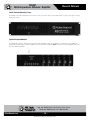
Owner’s Manual
F6-MF
Multi-Impedance Modular Amplifier
F6-MF
Multi-Impedance Modular Amplifier
1601 Jack McKay Blvd. • Ennis, Texas 75119 U.S.A.
Telephone: 800.876.3333 • Fax: 800.765.3435
– 1 –
Specifications are subject to change without notice.
AtlasSound.com
F6-MF
Multi-Impedance Modular Amplifier
Owner’s Manual
Table of Contents
Important Safety Instructions................................................................................................................... 3
Introduction ............................................................................................................................................ 5
Key Features and Applications................................................................................................................ 6
Front Panel Description............................................................................................................................ 7
Rear Panel Description............................................................................................................................. 8
FM250-4 & FM250-70 Power Module Features ..................................................................................... 9
Setting the FM Module Function Switch.................................................................................................10
FM250 Amplifier Module Installation .....................................................................................................11
Tamper-Proof Security Cover ................................................................................................................. 12
Optional Accessory Input Modules ....................................................................................................... 12
Placement of the F6-MF ....................................................................................................................... 13
Cabling the F6-MF ................................................................................................................................. 13
Specifications ........................................................................................................................................ 14
Warranty................................................................................................................................................. 16
1601 Jack McKay Blvd. • Ennis, Texas 75119 U.S.A.
Telephone: 800.876.3333 • Fax: 800.765.3435
AtlasSound.com
– 2 –
Specifications are subject to change without notice.
Owner’s Manual
F6-MF
Multi-Impedance Modular Amplifier
Important Safety Instructions
The lightning flash with arrowhead symbol within an
equilateral triangle, is intended to alert the user to the
presence of uninsulated “dangerous voltage “ within the
product’s enclosure that may be of sufficient magnitude
to constitute a risk of electric shock to persons.
The exclamation point within an equilateral triangle is
intended to alert the user to the presence of important
operating and maintenance (servicing) instructions in the
literature accompanying the product.
1. Read these instructions.
2. Keep these instructions.
3. Heed all warnings.
4. Follow all instructions.
5. Do not use this device near water.
6. Clean only with dry cloth.
7. Do not block any ventilation openings. Install in accordance with the manufacturer’s instructions.
8. Do not install near any heat sources such as radiators, heat registers, stoves, or other device (including amplifiers)
that produce heat.
9. Do not defeat the safety purpose of the polarized or grounding-type plug. A polarized plug has two blades with one wider than the
other. A grounding type plug has two blades and a third grounding prong. The wide blade or the third prong are provided for your safety. If the provided plug does not fit into your outlet, consult an electrician for replacement of the obsolete outlet.
10. Protect the power cord from being walked on or pinched particularly at plugs, convenience receptacles, and the point where they exit from the device.
11. Only use attachments/accessories specified by the manufacturer.
12. Use only with the cart, stand, tripod, bracket, or table specified by the manufacturer, or sold with the device. When a cart is used, use caution when moving the cart/device combination to avoid injury from tip-over.
13. Unplug this device during lightning storms or when unused for long periods of time.
14. Refer all servicing to qualified service personnel. Servicing is required when the device has been damaged in any way, such as power-supply cord or plug is damaged, liquid has been spilled, or objects have fallen into the device, the device has been exposed to rain or moisture, does not operate normally, or has been dropped.
15. WARNING: To reduce the risk of fire or electric shock, this device should not be exposed to rain or moisture and objects filled with liquids, such as a vase, should not be placed on this device.
16. To completely disconnect this equipment from the mains, disconnect the power supply cord plug from the receptacle.
17. The mains plug of the power supply cord shall remain readily operable.
1601 Jack McKay Blvd. • Ennis, Texas 75119 U.S.A.
Telephone: 800.876.3333 • Fax: 800.765.3435
– 3 –
Specifications are subject to change without notice.
AtlasSound.com
F6-MF
Multi-Impedance Modular Amplifier
•
•
•
•
•
•
•
•
•
•
•
•
•
•
•
•
•
•
•
•
•
•
Owner’s Manual
WARNING When The Device Is In Use
To prevent electric shock, do not remove the product cover as there are high voltage components inside. Refer all servicing to
Atlas Sound.
Should any of the following irregularities occur during use, immediately switch off the power, disconnect the power cord from the AC outlet and contact Atlas Sound. Do not to attempt to continue operation with the product as this may cause fire or electric shock:
• Smoke or strange smell coming from the unit.
• If the product falls or the case is damaged.
• If water or any metallic objects falls into the product.
• If the power supply cord is damaged in any way.
• If the unit is malfunctioning.
Do not insert or drop metallic objects or flammable materials into the ventilation holes of the product's cover, as this may result in electric shock or fire.
Do not place any containers with liquid or metallic objects on the top of the product. If any liquid spills into the unit, fire or electric shock may result.
Never operate this product or touch the power supply cord during an electrical storm, electric shock may result.
Never exceed the power rating on the product when connecting equipment. Fire and/or property damage may result.
Operate the product only with the voltage specified on the unit. Fire and/or electric shock may result if a higher voltage is used.
Do not modify, kink, or cut the power cord. Do not place the power cord in close proximity to heaters and do not place heavy objects on the power cord, including the product itself, doing so may result in fire or electrical shock.
Replace the protective cover over the speaker terminals after installation. Do not touch the 70V speaker terminals as electric shock may result.
Ensure that the safety ground terminal is connected to a proper ground. Never connect the ground to a gas pipe as a catastrophic disaster may result.
Be sure the installation of the product is stable, avoid slanted surfaces as the product may fall and cause injury or property damage.
CAUTION When Installing The Product
Plugging in or unplugging the power cord with wet hands may result in electric shock.
Never move the unit with the power cord plugged into the wall, as damage to the power cord may result.
When unplugging the cord from the wall, grasp the plug, NOT the cord.
Never install this product in humid or dusty locations, nor in direct sunlight, near sources of heat, or in areas where sooty smoke or steam are present. Fire and electric shock may result.
Keep all sides of the unit at least 31⁄2" away from objects that may obstruct air flow to prevent the unit's internal temperature rise.
CAUTION When The Product Is In Use
When powering the product up for the first time, ensure that the level control is turned down. Unexpected high sound pressure levels may be present at the speakers and result in hearing loss.
Never place heavy objects on the product, causing it to fall and/or break, resulting in personal injury and property damage. In addition, the product itself may fall and cause injury and property damage.
Never operate the product for extended periods with the sound in a distorted condition. This is an indication of a malfunction, which may result in excessive heat being generated and causing a fire.
Contact Atlas Sound for instructions on cleaning the inside of the unit. Large accumulations of dust inside the unit may result in heat buildup and fire.
Ensure that the power supply plug is securely plugged into the wall outlet. Never allow dust to accumulate on the power plug or inside the wall outlet.
When cleaning the unit or the unit is not to be operated for an extended period, unplug the power cord from the wall.
1601 Jack McKay Blvd. • Ennis, Texas 75119 U.S.A.
Telephone: 800.876.3333 • Fax: 800.765.3435
AtlasSound.com
– 4 –
Specifications are subject to change without notice.
Owner’s Manual
F6-MF
Multi-Impedance Modular Amplifier
Thank you for purchasing the Atlas Sound F6-MF Multi-Impedance Modular Amplifier. The innovative design of the F6-MF allows
the amplifier to be configured to suit the individual amplification and sound system requirements of a variety of applications. This
functionality makes the F6-MF one of the most flexible, energy efficient amplifiers on the market today.
The F6-MF Chassis can be fitted with up to six uniquely engineered amplifier modules. The straight-path design of the F6-MF is the
essence of simplicity; yielding clean, accurate, and dynamic sound. The FM250-4 (4Ω/8Ω) and FM250-70 (70.7V) power modules
can be loaded into any of the six F6-MF amplifier card slots and are designed to deliver up to 250 Watts per channel. The Ultra Fast
Recovery Switch Mode power supply is routed to each output module through quad-ganged connector contacts to minimize the
impedance path allowing for maximum current delivery. Each amplifier module includes its own power supplied, high-current, low ESR
(Equivalent, Series Resistance) capacitors which provide immediate local, on demand current. This allows each channel to produce
clean, instantaneous, high-impact audio power. The direct coupled power supply is designed to route any and all available energy to
the channels that require it. This innovative feature known as Power Rail Direct Coupling™, or PRDC, technology enables channels that
demand more energy to benefit from the pooled resources so they can deliver more power efficiently.
The F6-MF Chassis can be purchased with up to six FM250-4 of FM250-70 modules in any combination. Additional modules can also be
ordered as needed to satisfy future system or purchasing requirements. The F6-MF and FM250 Power Modules are loaded with useful
features including Front and Rear channel status indicators, selectable gain, signal limiters, 100Hz Hi-Pass filter, bridge mode operation,
and tamper-resistant level controls.
The FM250 Series Power Modules are designed to be 90% efficient, allowing the amplifier to run cooler and consume less energy than
conventional commercial amplifiers. To ensure all channels run cool, Atlas Sound has designed the F6-MF with a sophisticated forced air
cooled tunnel system. The input design of the F6-MF is based on an open architecture concept, permitting application and installation
flexibility. Six balanced inputs via Phoenix termination feed a variety of optional accessory interface cards, increasing the functionality
and performance of the F6-MF.
The F6-MF offers an Energy Save Mode called "Standby". The amplifier can be turned on remotely via a Contact Closure (CC) or a
DC Voltage of 5V - 24V. An LED located on both the Front & Rear panels of the F6-MF indicates the operation mode of the amplifier.
While in Standby, the F6-MF draws an incredibly low amount of energy, 5 Watts, making the amplifier meet the Energy Star rating for
commercial products. In Activation mode, the F6-MF is designed for maximum power efficiency utilizing the most advanced topology
available. The FM Series Power Modules are 90% efficient, combining with the Power Savings Mode, making the F6-MF more power
efficient with a higher power handling than other commercial amplifiers available.
Additional input cards, i.e. FM-AMIX and FM-IPDSP, are also available to increase the flexibility of the F6-MF system. The cost effective
FM-AMIX Analog Input Mixer Card is feature loaded with stereo summed and Mic/Line inputs with global assignment and remote mute
priority capabilities. The FM-IPDSP Input Card incorporates the latest DSP and IP technologies to allow the user to adjust a wide array
of signal parameters, and it serves as an interface for control and system monitoring of all amplifier channels from a remote location.
All of these standard features and optional accessories make the F6-MF Multi-Impedance Modular Amplifier the ideal choice for the
demanding requirements of today’s amplifiers.
1601 Jack McKay Blvd. • Ennis, Texas 75119 U.S.A.
Telephone: 800.876.3333 • Fax: 800.765.3435
– 5 –
Specifications are subject to change without notice.
AtlasSound.com
F6-MF
Multi-Impedance Modular Amplifier
Owner’s Manual
Key Features
• Supports up to 6 Amplifier Channels
• Light Weight Power Rail Direct Coupling™ (PRDC) Technology
• Ultra-Efficient Class D Amplification Topology
• Ultra Fast Recovery Switch Mode Power Supply
• Modular Design, Purchase the Number of Channels Needed
• Energy Save Mode, Remote Activation
• 4Ω/8Ω Amplifier Power Modules
• 70.7V Amplifier Power Modules
• Balanced Inputs via Phoenix Connector
• Front and Rear LED Status Indicators
• Optional Gain Selections
• Selectable Hi-Pass Filter per Channel
• Tamper-Resistant Level Controls
• Individual Channel Protection
• Optional Input Modules, DSP Signal Processing and Analog Mixer
Applications
The Atlas Sound F6-MF Multi-Impedance Modular Amplifier can be used for a number of applications. Due to its modular design,
the F6-MF is ideal for addressing today's system needs as well as future system expansion; including but not limited to boardroom,
restaurant, commercial paging, and background music applications. Each amplifier card slot of the F6-MF can accept either a 4Ω/8Ω or
70.7V amplifier module card, enabling complete system design flexibility, making it the ideal multi-faceted amplifier.
The F6-MF Multi-Impedance Modular Amplifier can be used in a single-channel or multi-channel amplifier configuration. The superior
sonic quality allows the F6-MF to be used in a high end surround system while the 70.7V amplifier modules allow the F6-MF to ideally
perform when paging into a multi-zone configuration. The F6-MF can also function in cross-application settings such as restaurants
and night clubs. Channels can operate independently of one another, allowing for example, one or two channels to be designated for
background paging while the remaining channels can be used with the night club's dance floor system.
Each channel itself can produce 250 watts at 4Ω or 70.7V at 0.15% THD. When all channels are driven with a sine wave simultaneously
to full power, continuous output is 170 Watts at 4Ω or 170 Watts into 70.7V. Because of the PRDC technology under real life audio
power requirements, the F6-MF can deliver over 250 Watts dynamic power all channels driven. Refer to the specification page for full
details.
1601 Jack McKay Blvd. • Ennis, Texas 75119 U.S.A.
Telephone: 800.876.3333 • Fax: 800.765.3435
AtlasSound.com
– 6 –
Specifications are subject to change without notice.
F6-MF
Multi-Impedance Modular Amplifier
Owner’s Manual
Front Panel
2
1
3
4
1. System LED Indicators
Power
When
AC Mains power is applied to the F6-MF and the AC Mains Power Switch is in the “On” position, this LED will
illuminate Blue indicating the F6-MF is ready for use.
Temp
This
LED represents the temperature condition of the Mainframe. The LED will illuminate Yellow if any of the FM250
amplifier channels reaches 10% of their Thermal Protect shut off and the fan cooling system is at its maximum cooling
capability. Also refer to the Protect LED below.
Standby
the Standby LED is illuminating Orange, it means the F6-MF is in Energy Save Mode. The F6-MF can be turned on
If
via three methods; Power Switch, DC Voltage, or Contact Closure. Note: The F6-MF is shipped with a shunt across
the CC contacts to activate the amp from Standby Mode. This is to be used when remote activation is not required.
If the Standby LED is not illuminating, the Front Panel Blue LED Power LED will be illuminated and, the FM Module's
Ready LEDs (Green) will be on. This means the amplifier is ready to use. If not, check the AC Mains and power switch.
2. Module LED Status Indicators for Each Channel
ReadyThis LED will illuminate Green when an FM250 power module is installed on the appropriate channel and the F6-MF is
turned on.
SignalThe channel Signal LED will illuminate Green when the FM250 amplifier output signal produces a minimum 1 Watt
output.
Limit
The
Limit LED will illuminate Yellow under load conditions. If the FM250 function switch is set to Limit then the LED
acts as a maximum level indicator. If the FM250 channel Limit function is off, the LED reacts as a Clip indicator. Also,
under Low Impedance loads, this LED serves as a current Limit indictor.
Protect
The
Protect LED will illuminate Red during one the following conditions. No output will occur while this LED is
illuminated. It will reset itself after the condition has been corrected.
1) Shorted speaker output.
2) Thermal Shut Off. The Temp F6-MF TEMP LED will also be illuminated.
3) Current Overdrive. If the amplifier channel is driving too low of a speaker load.
3. Channel Level Controls
There
are six detented level controls, one for each of the F6-MF's six FM250 channel card slots. When any of the potentiometers
is turned down (left or FCC (Fully Counter Clockwise)), no signal will come out of the corresponding amp channel. When the
potentiometer is turned up (right to the eighth detent or FC (Fully Clockwise)), the amp will be set for maximum level.
4. Air Exhaust
The F6-MF has fan assist cooling and draws cool air in from the rear of the amp and exhausts the hot air out of the front panel.
1601 Jack McKay Blvd. • Ennis, Texas 75119 U.S.A.
Telephone: 800.876.3333 • Fax: 800.765.3435
– 7 –
Specifications are subject to change without notice.
AtlasSound.com
F6-MF
Multi-Impedance Modular Amplifier
Owner’s Manual
Rear Panel Features
1
2
5
4
3
6
9
8
7
1. AC Mains Power Switch
Connect
this grounded power cord to 120VAC circuits only. Serious damage may result otherwise. The fuse for the F6-MF is internal to
the amplifier; only qualified personnel should replace the fuse, if necessary.
2. AC Mains Power Cord
Insert the IEC Power Cord into the receptacle making sure it is securely placed. Prior to plugging the F6 Power Cord into an AC source,
make sure the AC Mains Voltage select switch is in the correct position. Series damage may result otherwise.
3. AC Mains Select
rior to plugging the AC Mains Power Cord to an AC source, determine the proper AC Mains voltage the amplifier will see. For voltages
P
between 103V - 127V, select 115V. For voltages between 207V - 253V, select the 230V switch position. Note: If the AC Mains Voltage
Switch is in the incorrect position when the power cord is plugged into an AC Mains the unit will trigger a protect circuit and the Over
Voltage LED will illuminate.
4. Over Voltage LED
If the Over Voltage LED is illuminating Red, it means the AC Mains Voltage Select Switch is in the incorrect position or the AC Mains
Voltage exceeded the operating range. Note: Unplug the AC Power Cord prior to changing the switch selection.
5. Standby LED
If the Standby LED is illuminating Orange, it means the F6-MF is in Energy Save Mode. The F6-MF is shipped with a shunt across the
CC contacts to activate the amp from Standby mode. This is to be used when remote activation is not required. If the standby LED is
not illuminating, the Front Panel Blue LED Power LED will be illuminated and the FM Modules' Ready LEDs (Green) will be on. This
means the amplifier is ready to use. If not, check the AC Mains and Power Switch.
6. System Activation
he F6-MF is activated via two methods. Contact Closure, shorting the CC and Ground Terminal together or by applying a DC Voltage
T
5–24V (+V) and the Ground (–). Note: For the F6-MF to turn ON, the AC Mains Power Switch needs to be in the "ON" position and the
contact closure must be shorted or have a DC voltage applied.
7. Balanced Input Connections
alanced line level signals connect to the (+) (–) and (G) terminals. Note: If you are connecting an unbalanced line level input, tie (short)
B
the (G) and (–) terminals together.
8. FM250 Amplifier Module Channel Slots
he F6-MF is shipped with no FM250 amplifier modules. There are 6 empty card slots in a F6-MF . Each slot is shipped with a blank
T
filler panel covering each unoccupied slot. Note: If a slot is not being used, it is important that the blank cover plate is installed. Without
blank cover plate, amplifier cooling issues may occur.
9. Optional Accessory Input
This slot is for optional accessory items such as the FM-AMIX and the FM-IPDSP. Please refer to their manuals for installation procedure.
1601 Jack McKay Blvd. • Ennis, Texas 75119 U.S.A.
Telephone: 800.876.3333 • Fax: 800.765.3435
AtlasSound.com
– 8 –
Specifications are subject to change without notice.
F6-MF
Multi-Impedance Modular Amplifier
Owner’s Manual
FM250-4 and FM250-70 Module Features
FM250 - 4
FM250 -70
250W @ 4Ω
250W @ 70V
Protect
Protect
Limit
Limit
Signal
Signal
Ready
Ready
70V
4Ω
Speaker Output
Class 2 Wiring
Speaker Output
Class 2 Wiring
1. M
odule Status Indicators
Note: They also parallel Status LED on the front panel of the F6-MF panel.
ReadyThis LED will illuminate Green when an FM250 power module is installed on the appropriate channel and the F6-MF is
turned on.
SignalThe channel Signal LED will illuminate Green when the FM250 amplifier output signal produces a minimum 1 Watt
output.
Limit
The
Limit LED will illuminate Yellow under load conditions. If the FM250 function switch is set to Limit then the LED
acts as a maximum level indicator. If the FM250 channel Limit function is off, the LED reacts as a Clip indicator. Also,
under Low Impedance loads, this LED serves as a current Limit indictor.
Protect
The
Protect LED will illuminate Red during one the following conditions. No output will occur while this LED is
illuminated. It will reset itself after the condition has been corrected.
1) Shorted speaker output.
2) Thermal Shut Off. The Temp F6-MF TEMP LED will also be illuminated.
3) Current Overdrive. If the amplifier channel is driving too low of a speaker load.
2. Speaker Connections
A removable Phoenix/Euro Block type connector is supplied to connect your speakers to the FM250 amplifier module. It is
recommended to use 16-gauge wire or lower for connection to the speakers. Note: Do not overload the amp by connecting too many
speakers to the amp.
1601 Jack McKay Blvd. • Ennis, Texas 75119 U.S.A.
Telephone: 800.876.3333 • Fax: 800.765.3435
– 9 –
Specifications are subject to change without notice.
AtlasSound.com
1 Color: White
F6-MF
Multi-Impedance Modular Amplifier
Owner’s Manual
FM250-4 & FM250-70 Function Switch
FM250 Module Dip Switch Functions are located near the rear of the FM250 modules. Note: It is essential to preset your setting prior
to inserting the module into the F6-MF.
Factory Dip Switch Presets
Dip Switch 1 ships in the “On” position. Dip Switches 2 & 3 ship in the “Off” position.
Dip Switch 1, Gain
When placed in the “On” position the channel’s Gain or Input Sensitivity will be 1V (0dBV) for rated output. When placed in the “Off”
position the Gain is set to 2V (6dBV).
Dip Switches 2 & 3, HPF
The High Pass Filter (HPF) when placed into the “On” position engages a 100Hz / 12dB filter. When in the “Off” position the module
operates at full audio bandwidth.
1601 Jack McKay Blvd. • Ennis, Texas 75119 U.S.A.
Telephone: 800.876.3333 • Fax: 800.765.3435
AtlasSound.com
– 10 –
Specifications are subject to change without notice.
F6-MF
Multi-Impedance Modular Amplifier
Owner’s Manual
FM250 Amplifier Module Installation
Align Modules to
Top & Bottom Card
Guides
Use the following steps and read all steps prior to installation.
1. Turn F6-MF AC Power Switch to the “Off” position.
2. Turn down all level controls on the front panel.
3. Remove the blank card slot cover. Do not discard the two screws, you will need them later.
4. Set the function switches on the FM250 module. (See Page 10)
5. C
arefully and slowly guide the module into the slot with the PCB components facing to the right. Note: The module heatsink
top and bottom metal edge mate with the mainframe plastic card guides. Do not force the card. Realign if necessary.
6. A
fter the module is pushed in and in contact with the back plane of the PCB assembly mating connector, firmly press the
module in completing the connection. If the module plate is flush to the F6-MF, the module is fully seated.
7. Insert the two screws from the cover pate. Some minor alignment may be required.
1601 Jack McKay Blvd. • Ennis, Texas 75119 U.S.A.
Telephone: 800.876.3333 • Fax: 800.765.3435
– 11 –AtlasSound.com
Specifications are subject to change without notice.
F6-MF
Multi-Impedance Modular Amplifier
Owner’s Manual
Level Control Security Cover
The F6-MF comes with a tamper-proof level control security cover. There are two screws that hold the security cover in place covering
all six level controls.
Optional Input Module
The F6-MF has a variety of optional accessory input modules available. Please contact Atlas for a current list. Prior to installing any
optional input module, please read the installation sheet for that model completely. Note: All accessory module installations are to be
done by a qualified technician.
1601 Jack McKay Blvd. • Ennis, Texas 75119 U.S.A.
Telephone: 800.876.3333 • Fax: 800.765.3435
AtlasSound.com
– 12 –
Specifications are subject to change without notice.
Owner’s Manual
F6-MF
Multi-Impedance Modular Amplifier
Placement of the F6
Turn off all equipment before making connections. Mount the F6-MF in a standard width 19" rack. It can be mounted above or below
anything that does not generate excessive heat. Although the unit’s chassis is shielded against radio frequency and electromagnetic
interference, extremely high fields of RFI and EMI should be avoided.
Ventilation
The unit should be situated so that its location or position does not interfere with its proper ventilation. For example, the F6-MF should
not be situated in a sealed cabinet or on a shelf with obstacles on it that may impede the flow of air through the ventilation openings. It
is recommended that if the amp is not used in an open air pole mount that it be rack mounted into a commercial rack.
Heat
The F6-MF should be situated away from heat sources such as radiators, heat registers, stoves, or other appliances (including
amplifiers) that produce excessive heat. Ambient temperatures should not exceed 113°F (45°C) when equipment is in use.
Cabling of the F6
The F6-MF can be used with either balanced or unbalanced sources, and the outputs can be used with either balanced or unbalanced
loads provided the proper cabling is used. A balanced line is defined as two-conductor shielded cable with the two center conductors
carrying the same signal of opposite polarity when referenced to ground. An unbalanced line is generally a single-conductor shielded
cable with the center conductor carrying the signal and the shield at ground potential.
Balanced Input
Use 2 conductor wire shielding for low level signals, 20 to 22 gauge is best. Maintain the proper polarity, + to +, – to –, and shield to
ground. Note: The ground center pin of the Phoenix connector is common for both channels.
Speaker Outputs
Use 2 conductor unshielded wire of the appropriate gauge. If you are unsure about this, contact Atlas Sound Tech Support at
1-800-876-3333. Make sure you know how many speakers you need and what tap value you intend to use.
1601 Jack McKay Blvd. • Ennis, Texas 75119 U.S.A.
Telephone: 800.876.3333 • Fax: 800.765.3435
– 13 –AtlasSound.com
Specifications are subject to change without notice.
F6-MF
Multi-Impedance Modular Amplifier
Owner’s Manual
Specifications
Type
Six Channel Main Frame
Amplifier modules FM250-4 & FM250-70
Class D Topology
Output Power FM250-4
Burst power 1kHz, Ultra Fast Recovery Power Supply
8Ω:
1 Channel
- 150 Watts
2 Channels
- 140 Watts Each
6 Channels
- 125 Watts Each
4Ω:
1 Channel
- 300 Watts
2 Channels
- 280 Watts Each
6 Channels
- 250 Watts Each
Continuous power 1kHz
8Ω:
1 Channel
- 135 Watts
2 Channels
- 125 Watts Each
6 Channels
- 95 Watts Each
4Ω:
1 Channel
- 270 Watts
2 Channels
- 250 Watts Each
6 Channels
- 170 Watts Each
Output Power FM250-70Burst power 1kHz, Ultra Fast Recovery Power Supply
1 Channel
- 300 Watts
2 Channels
- 280 Watts Each
6 Channels
- 250 Watts Each
Continuous Power 1khz, 30 Min
1 Channel
- 270 Watts
2 Channels
- 250 Watts Each
6 Channels
- 170 Watts Each
1601 Jack McKay Blvd. • Ennis, Texas 75119 U.S.A.
Telephone: 800.876.3333 • Fax: 800.765.3435
AtlasSound.com
– 14 –
Specifications are subject to change without notice.
F6-MF
Multi-Impedance Modular Amplifier
Owner’s Manual
THD + Noise
30Hz – 20kHz, +0/-1.5dB
Typically <0.2%, 1kHz, at Rated Output
0.15%, Typical Residual
Note: Characteristic Distortion is Almost Entirely 2nd Harmonic
Front Panel Features
6 Detented Level Controls, Mains Power LED, Temp LED
Frequency Response30Hz – 20kHz (±1dB) Fixed 30Hz Hi-Pass Filter
Protection CircuitsAC fuse 12A 250V
Thermal, Short Circuit, Limiter, Inrush
Signal to Noise Ratio-90dB Below Rated Output (Weighted)
Input SensitivitySelectable Per Channel 1V or 2V
Voltage Gain
30dB Per Channel
Input Impedance
Balanced 20k
Cooling
Fan Assist, Rear Intake, Front Exhaust
Power Delay On
1 – 2 sec.
Power Requirement
Global Selection 103V - 127V or 207V - 253V
Power Consumption
(at 120VAC)
Standby - 5 Watts
F6-MF (6 Channels Loaded)
Max - 1650 Watts, 14A, 5630 BTU
Average - 550 Watts, 4.5A, 1876 BTU
Idle - 16 Watts, 130mA, 54 BTU
FM250-4 & FM250-70
Max - 275 Watts, 2.33A, 938 BTU
Average - 91 Watts, .77A, 310 BTU
Main Frame Dimensions 19" Width x 3.5" Height x 13.5" Depth
(483mm x 89mm x 343mm)
Main Frame Weight
21lbs (9.5Kg) Unit
FM250 Module Dimensions1.5" Width x 3.4" Height x 10.6" Depth
(38mm x 86mm x 269mm)
FM250 Module Weight
0.8 lbs (.36Kg)
Note: Average Power is 1⁄3 rating, based on 25% head room, and 50% duty cycle.
Note: To calculate power consumption for an F6-MF with less than six FM250 modules loaded, multiply the single FM250 power rating
by the number of modules to be used.
1601 Jack McKay Blvd. • Ennis, Texas 75119 U.S.A.
Telephone: 800.876.3333 • Fax: 800.765.3435
– 15 –AtlasSound.com
Specifications are subject to change without notice.
F6-MF
Multi-Impedance Modular Amplifier
Owner’s Manual
Limited Warranty
All products manufactured by Atlas Sound are warranted to the original dealer/installer, industrial or commercial purchaser to be free
from defects in material and workmanship and to be in compliance with our published specifications, if any. This warranty shall extend
from the date of purchase for a period of three years on all Atlas Sound products, including SOUNDOLIER brand, and ATLAS SOUND
brand products except as follows: one year on electronics and control systems; one year on replacement parts; and one year on
Musician Series stands and related accessories. Additionally, fuses and lamps carry no warranty. Atlas Sound will solely at its discretion,
replace at no charge or repair free of charge defective parts or products when the product has been applied and used in accordance
with our published operation and installation instructions. We will not be responsible for defects caused by improper storage, misuse
(including failure to provide reasonable and necessary maintenance), accident, abnormal atmospheres, water immersion, lightning
discharge, or malfunctions when products have been modified or operated in excess of rated power, altered, serviced or installed
in other than a workman like manner. The original sales invoice should be retained as evidence of purchase under the terms of this
warranty. All warranty returns must comply with our returns policy set forth below. When products returned to Atlas Sound do not
qualify for repair or replacement under our warranty, repairs may be performed at prevailing costs for material and labor unless there is
included with the returned product(s) a written request for an estimate of repair costs before any nonwarranty work is performed. In the
event of replacement or upon completion of repairs, return shipment will be made with the transportation charges collect.
EXCEPT TO THE EXTENT THAT APPLICABLE LAW PREVENTS THE LIMITATION OF CONSEQUENTIAL DAMAGES FOR PERSONAL
INJURY, ATLAS SOUND SHALL NOT BE LIABLE IN TORT OR CONTRACT FOR ANY DIRECT, CONSEQUENTIAL OR INCIDENTAL LOSS
OR DAMAGE ARISING OUT OF THE INSTALLATION, USE OR INABILITY TO USE THE PRODUCTS. THE ABOVE WARRANTY IS IN
LIEU OF ALL OTHER WARRANTIES INCLUDING BUT NOT LIMITED TO WARRANTIES OF MERCHANTABILITY AND FITNESS FOR A
PARTICULAR PURPOSE.
Atlas Sound does not assume, or does it authorize any other person to assume or extend on its behalf, any other warranty, obligation,
or liability. This warranty gives you specific legal rights and you may have other rights which vary from state to state.
Service
Should your F6-MF amplifier require service, please contact the Atlas Sound warranty department at
1-877-689-8055, ext. 277 to obtain an RA number.
Atlas Sound Tech Support can be reached at 1-800-876-3333.
Visit our website at www.AtlasSound.com to see other Atlas products.
©2012 Atlas Sound L.P. All rights reserved. Atlas Sound is a trademark of Atlas Sound L.P.
All other trademarks are the property of their respective owners. ATS003096 RevD 4/12
1601 Jack McKay Blvd. • Ennis, Texas 75119 U.S.A.
Telephone: 800.876.3333 • Fax: 800.765.3435
AtlasSound.com
– 16 –
Specifications are subject to change without notice.