1
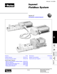
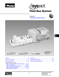
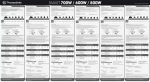
Air Preparation Products Catalog 0600P-E Warning, Offer of Sale ! WARNING FAILURE OR IMPROPER SELECTION OR IMPROPER USE OF THE PRODUCTS AND/OR SYSTEMS DESCRIBED HEREIN OR RELATED ITEMS CAN CAUSE DEATH, PERSONAL INJURY AND PROPERTY DAMAGE. This document and other information from Parker Hannifin Corporation, its subsidiaries and authorized distributors provide product and/or system options for further investigation by users h aving technical expertise. It is important that you analyze all aspects of your application including consequences of any failure, and review the information concerning the product or system in the current product catalog. Due to the variety of operating conditions and applications for these products or systems, the user, through its own analysis and testing, is solely responsible for making the final selection of the products and systems and assuring that all performance, safety and warning requirements of the application are met. The products described herein, including without limitation, product features, specifications, designs, availability and pricing, are subject to change by Parker Hannifin Corporation and its subsidiaries at any time without notice. Offer of Sale The items described in this document are hereby offered for sale by Parker Hannifin Corporation, its subsidiaries or its authorized distributors. This offer and its acceptance are governed by the provisions stated on the separate page of this document entitled “Offer of Sale”. © Copyright 2010-2005 Parker Hannifin Corporation. All Rights Reserved Parker Hannifin Corporation Pneumatic Division Richland, Michigan www.parker.com/pneumatics (Revised 7-12-2013) Click here to view bookmarks. Catalog 0600P-E Pneumatic Products Index Introduction “XM” Series Direct Acting 15mm Solenoid Valve Moduflex Series Stacking “PVL” Series Viking Lite Viking Xtreme Inline “B” Series “ADEX” Series “N” Series Isys Micro Series Isys ISO Series Subbase & Manifold Fieldbus Systems “DX” ISOMAX Series Valvair II Directair 2 & 4 Series, Manual / Mechanical “42” Lever / Pedal Series Viking Xtreme Lever Series Manual / Mechanical “M0” Series “LV” / “EZ” Lockout Valves Brass Poppet / Sliding Seal / “PL”/“VL” / “HV” Control Panel Products Accessories Sensing Flow Controls & Accessories Safety Guide, Offer of Sale 2 Parker Hannifin Corporation Pneumatic Division Richland, Michigan www.parker.com/pneumatics Pneumatic Products Catalog 0600P-E Index • Compact & Simplified Design • Subbase or Manifold Option • 3-Way • NO & NC on Same Manifold • Wide Range of Voltage • .033 to .05 Cv www.parker.com/pneu/15mm • Stand Alone Valves • Valve Island • Collective Wiring or Fieldbus Configuration • 3-Way & 4-Way • Modular & Flexible Design • Multiple Pressure Option • Compact & Low Weight • .18 to .80 Cv • Compact Composite Design • Modular with a Wide Range of Voltages • 3-Way & 4-Way • Fieldbus Available • .6 to 1.2 Cv • Inline valve. Optional aluminum bar manifolds • 3 valve sizes: 1/8, 1/4 & 3/8. CV: 0.6 to 2.5 • Pressures up to 145 PSIG & temperatures between 14°F to 122°F • Bi-directional WCS spool • Extreme Temperature & Pressure Ranges • ATEX Options • 4-Way • Wide Range of Voltages for Mobile Industries • Unique Overmoulded Spool Technology • .7 to 2.7 Cv • Wide Range of Sizes & Flows • Multiple Options • IEM Bar Manifold • 3-Way & 4-Way • Wear Compensating Dynamic Sealing System • .75 to 7.0 Cv • 10mm 3-Way • 15mm & 20mm 4-Way • Low Power Consumption • Subbase & Inline Body • Individual & Collective Wiring Solutions • .01 to.47 Cv • Robust Poppet Design • Fast Response & High Flow • 2-Way & 3-Way • High Maximum Pressure Option • 3.6 to 29.9 Cv www.parker.com/pneu/moduflex www.parker.com/pneu/pvl B C Stacking www.parker.com/pneu/xm www.parker.com/pneu/viking www.parker.com/pneu/vikingx www.parker.com/pneu/b D Inline • Direct Acting Solenoid • 3-Way & 4-Way • Inline • IEM Bar Manifold • Subbase Valve Manifolds • .15 Cv Direct Acting A • Valve Selector Chart (By Flow) • Fieldbus Solutions Guide • Fluid Power Graphic Symbols • Technical Information • 5-Year Warranty www.parker.com/pneu/adex www.parker.com/pneu/n • Isys Micro Fieldbus • Moduflex Fieldbus • Isysnet Fieldbus • Turck Fieldbus www.parker.com/pneu/isysnet • ISO Valve Platform, 18mm, 26mm, Size 1, Size 2, & Size 3 • Non Plug-in Valves with 3-Pin Din or Mini Connectors • .55 to 4.15 Cv www.parker.com/pneu/isomax • Robust Spool Design • Fast Response & High Flow • Plug-in & Direct Pipe Design • 4-Way • Hazardous Duty Option • 1.9 to 12.0 Cv • Robust Poppet & Spool Designs • 3-Way & 4-Way • Manual & Mechanical • Plunger, Roller, One-Way Tripper, Button, Hand Lever, Togglel, Treadle • 1/8" & 1/4" NPT • .17 to .83 Cv • Heavy Duty Design • 4-Way • Lever, Pedal Operated • 1/4" & 3/8" NPT • 1.3 to 2.8 Cv www.parker.com/pneu www.parker.com/pneu/directair www.parker.com/pneu/42ser www.parker.com/pneu/vikingx • Heavy Duty Lever Operated • 4-Way • 1/8 to 1/2" NPT • .7 to 2.7 Cv • Heavy Duty Design • Bronze Body • 3-Way & 4-Way, Air Pilot Manual & Mechanical Valves • 1/4" to 1" NPTF Ports • 2.4 to 12.4 Cv • Compliant with OSHA Standard 29 CFR 1910 • Lockout / Soft Start • 3.7 to 14.0 Cv E Subbase & Manifold www.parker.com/pneu/isys www.parker.com/pneu F Manual Mechanical • ISO Valve Platform, 18mm, 26mm, Size 1, Size 2, & Size 3 Plug-in • Collective Wiring on Fieldbus or 25-Pin or M23 Cable • Non Plug-in Valves with 3-Pin Din or Mini Connectors • .55 to 6.0 Cv www.parker.com/pneu/isysmicro G Accessories • Compact Valves with High Flow • Innovative Back to Back Mounting Style with 4 Valves in a 42mm Width • Plug-in Design with Collective Wiring on Fieldbus or 25 Pin Cable • .35 Cv www.parker.com/pneu/lockout • Manual Valves • Lever & Button Operators • 1/8" thru 1/2" Ports • Wide Range of Sizes & Flows • .5 to 1.25 Cv www.parker.com/pneu/ssv • Variety of Control Panel Options - Push Buttons - Indicators - Foot Pedals • Large Selection of Options • Two-Hand Control Conformance with EN 574 www.parker.com/pneu/cpp • Large Variety of Limit & Pressure Switches • Limit Switches for Standard & Heavy Duty Service • Blocking Valves for Air, Gas & Liquid Service • Threshold Sensors for Monitoring Cylinder Exhaust • Flow Controls • Check Valves • Needle Valves • Muffler & Silencers • Relief Valves • Quick Exhaust Valves • Ball Valves • Fittings • Tubing & Hose • Quick Couplings www.parker.com/pneu/limsen www.parker.com/pneu/accessories H • Model Number to Page Number Index • Safety Guide • Offer of Sale 3 Parker Hannifin Corporation Pneumatic Division Richland, Michigan www.parker.com/pneumatics “XM” Series Air Control Valves Direct Acting, 1/8" Port 3-Way & 4-Way: .15 Cv XM Section B B 15mm Solenoid www.parker.com/pneu/xm Basic Valve Functions................................................ B2 Kits & Accessories..................................................... B9 XM Series Basic Features.......................................... B3 Dimensions....................................................... B10-B13 Common Part Numbers.............................................. B4 Model Number Index.................................................. B5 IEM Bar Manifolds & Subbase Manifolds................... B6 Manifold Ordering Information.................................... B7 Technical Information................................................. B8 BOLD ITEMS ARE MOST POPULAR. B1 Parker Hannifin Corporation Pneumatic Division Richland, Michigan www.parker.com/pneumatics “XM” Series Air Control Valves Air Control Valves Catalog 0600P-E Basic Valve Function 3-Way, 2-Position, Normally Closed B 3-Way, 2-Position, Normally Open 2 #12 #10 1 3 2 #12 #10 1 3 XM De-energized position – Solenoid #12 de-energized. Pressure at inlet port 1 blocked, outlet port 2 connected to exhaust port 3. De-energized position – Solenoid #12 de-energized. Pressure at inlet port 3 connected to outlet port 2, exhaust port 1 is blocked. Energized position – Solenoid #12 energized. Pressure at inlet port 1 is connected to outlet port 2, exhaust port 3 is blocked. Energized position – Solenoid #12 energized. Pressure at inlet port 3 blocked, outlet port 2 connected to exhaust port 1. 15mm Solenoid 3-Way, 2-Position, Diverter 3-Way, 2-Position, Selector 2 #12 #10 1 3 2 #12 #10 1 De-energized position – Solenoid #12 de-energized. Pressure at inlet port 2 connected to outlet port 3. Port 1 is blocked. De-energized position – Solenoid #12 de-energized. Pressure at inlet port 1 is blocked. Pressure at inlet port 3 is connected to outlet port 2. Energized position – Solenoid #12 energized. Pressure at inlet port 2 is connected to outlet port 1. Port 3 is blocked. Energized position – Solenoid #12 energized. Pressure at inlet port 1 is connected to outlet port 2. Pressure at port 3 is blocked. 2 2-Way, 2-Position, Normally Closed #12 2-Way, 2-Position, Normally Open #10 1 3 De-energized position – Solenoid #12 de-energized. Pressure at inlet port 1 blocked, port 2 is connected to port 3, which is plugged. 3 2 #12 #10 1 3 De-energized position – Solenoid #12 de-energized. Pressure at inlet port 3 is connected to outlet port 2. Port 1 is blocked. Energized position – Solenoid #12 energized. Pressure at inlet port 1 is connected to outlet port 2. Port 3 is blocked. Energized position – Solenoid #12 energized. Pressure at inlet port 3 is blocked. Port 2 is connected to port 1, which is plugged. * Plug port 3. * Plug port 1. 4-Way, 2-Position 2 4 1 3 #14 2 #12 4-Way, 2-Position with Flow Controls De-energized position – Solenoid #14 de-energized. Pressure at inlet port 1 connected outlet port 2. Outlet port 4 connected to exhaust port 3. 4 #14 #12 1 3 De-energized position – Solenoid #14 de-energized. Pressure at inlet port 1 connected outlet port 2. Outlet port 4 connected to exhaust port 3. Energized position – Solenoid #14 energized. Pressure at inlet port 1 is connected to outlet port 4. Outlet port 2 connected to exhaust port 3. Energized position – Solenoid #14 energized. Pressure at inlet port 1 is connected to outlet port 4. Outlet port 2 connected to exhaust port 3. Flow Controls meter exhaust from ports 2 and 4 separately into port 3. B2 Parker Hannifin Corporation Pneumatic Division Richland, Michigan www.parker.com/pneumatics “XM” Series Air Control Valves Air Control Valves Catalog 0600P-E Basic Valve Features Flow Characteristics • 3-Way: • 4-Way: .15 Cv .15 Cv B 3-Way Operating Pressure XM • 0 to 125 PSIG • 0.28" Hg Vacuum 15mm Solenoid 4-Way Operating Pressure • -14.7 to 125 PSIG Ports • 1/8" NPT Mounting 3-Way Inline Valve Shown Energized • Inline • IEM Bar Manifold • Subbase Valve Manifold Solenoids • Continuous Duty Rated • 24" Grommet • 15mm 3-Pin (9.4mm Pin Spacing) • 1/2" Conduit • 12VDC to 240VAC Balanced Poppet • 3-Way N.O. & N.C. • Diverter • Selector • Vacuum Option (V-Option) ROHS Compliant 4-Way Inline Valve Shown De-Energized Materials • Body............................................Aluminum • Center Post & Armature......Stainless Steel • Stem...................................................Brass • Spring . ...............................Stainless Steel • Seals...............................................Buna N Pressure B3 Exhaust Parker Hannifin Corporation Pneumatic Division Richland, Michigan www.parker.com/pneumatics “XM” Series Air Control Valves 3 & 4-Way, 2-Position Solenoid Catalog 0600P-E Common Part Numbers Inline Valves 2 #12 B 1 2 4 1 3 #14 #10 3 N.C. Function Shown #12 XM 15mm Solenoid 4-Way 3-Way Voltage 24" Grommet 3-Pin 15mm 1/2" Conduit / DIN 9.4mm 24" Leads XM30NBH49A 24VDC XM40NBG49A XM40NB549A XM40NBH49A 24VDC XM30NBH53A 120VAC XM40NBG53A XM40NB553A XM40NBH53A 120VAC 24" Grommet 3-Pin 15mm 1/2" Conduit / DIN 9.4mm 24" Leads XM30NBG49A XM30NB549A XM30NBG53A XM30NB553A Voltage Note: All units with non-locking flush override. Note: All units with non-locking flush override. Can be used as N.O / N.C. / Diverter / Selector function. Subbase Mount 2 #12 3 N.C. Function Shown 3-Way 1 3 #12 4-Way 24" Grommet 3-Pin 15mm DIN 9.4mm XM3VNBG49A XM3VNBG53A 4 #14 #10 1 2 Voltage 24" Grommet 3-Pin 15mm DIN 9.4mm Voltage XM3VNB549A 24VDC XM4VNBG49A XM4VNB549A 24VDC XM3VNB553A 120VAC XM4VNBG53A XM4VNB553A 120VAC Note: All units with non-locking flush override. Can be used as N.O / N.C. / Diverter / Selector function. Note: All units with non-locking flush override. B4 Parker Hannifin Corporation Pneumatic Division Richland, Michigan www.parker.com/pneumatics “XM” Series Air Control Valves 3 & 4-Way, 2-Position Solenoid Catalog 0600P-E Model Number Index BOLD OPTIONS ARE MOST POPULAR. B Operator / Function XM XM 4 0 N B G49 — A Engineering Level 3 4-Way, Direct Operated, Single Solenoid, Spring Return 4 A Current Port Size / Thread Type 15mm Solenoid 3-Way, Direct Operated, Single Solenoid, Spring Return Options 1/8" NPT Inline 0* Subbase Valve Less Base V Blank F0* * Available on IEM manifolds. None Flow Control * 4-Way Valves Only. Pilot Source / Exhaust Enclosures / Lead Length Direct Operated / Standard Pressure N* Direct Operated / Vacuum Service V** Voltage AC * 3-Way Valve Positive Pressure, 4-Way Valve Vacuum or Positive Pressure ** 3-Way Valve Vacuum Pressure. Overrides Flush - Non-Locking B 60Hz 50Hz 24 22 542 15mm 3-Pin DIN 9.4mm 545* 15mm 3-Pin DIN 9.4mm 549* 15mm 3-Pin DIN 9.4mm 553 15mm 3-Pin DIN 9.4mm 120 110 G42 Grommet / Flying Leads 24" 24 22 G45* Grommet / Flying Leads 24" 12 G49* Grommet / Flying Leads 24" 24 G53 Grommet / Flying Leads 24" 120 110 G57 Grommet / Flying Leads 24" 240 220 1/2" Conduit / Flying Leads 24" 24 22 H42 † 12 24 H45*† 1/2" Conduit / Flying Leads 24" 12 H49* 1/2" Conduit / Flying Leads 24" 24 H53 1/2" Conduit / Flying Leads 24" † † 120 110 * Mobile Voltage Rated. † Inline Version Only. Notes: Inline Valves Conduit Inline valves cannot be mounted to IEM or Subbase Manifolds. B5 DC Parker Hannifin Corporation Pneumatic Division Richland, Michigan www.parker.com/pneumatics IEM Bar Manifolds & Subbase Manifolds “XM” Series Air Control Valves Kits & Assemblies IEM Bar Manifold Assembly Subbase Manifold Assembly IEM Bar Manifold Subbase Manifold Allows for mounting of 3-Way and 4-Way Inline valves on the same manifold. 3-Way Valves can be mounted on the same manifold to provide a Normally Closed or Normally Open function by rotating the valves 180°. 4-Way valves can be mounted with or without Flow Controls. Allows for mounting of 3-Way and 4-Way Subbase Valves can be mounted on the same manifold. 3-Way Valves can be mounted on the same manifold to provide a Normally Closed or Normally Open function through the use of port isolation kits. 4-Way valves can be mounted with or without Flow Controls. Catalog 0600P-E B XM 15mm Solenoid IEM Bar Manifold Assemblies consist of valves and an IEM Manifold. Valves and IEM Manifold can be ordered separately. IEM Bar Manifold (NPT) Subbase Manifold Assemblies consist of Valves, End Plate Kit and Manifold Subbase Kits. Valves, End Plate Kit and Manifold Subbase Kits can be ordered separately. End Plate Kit (NPT) PSXM31010P Manifold Subbase Kit (NPT) PSXM530CP PSMXNXN##NP ## – stations 02 to 12 B6 Parker Hannifin Corporation Pneumatic Division Richland, Michigan www.parker.com/pneumatics “XM” Series Air Control Valves IEM Bar Manifolds & Subbase Manifolds How to Order Manifold Assemblies BOLD OPTIONS ARE MOST POPULAR. B AA PSJ XN X N 04 N P Options Operator / Function Manifold with Valves Mounted AA N Operator / Function None Number Stations IEM Manifold with Valves Mounted PSM Subbase Manifold with Valves Mounted PSJ 02 2 Stations • • • Cylinder Ports IEM Manifold X Subbase Manifold 1 12 12 Stations Port Type NPT N IEM Bar Manifold Assembly Subbase Manifold Assembly First line item describes IEM Assembly. Subsequent line items listed identify each station in the Manifold starting with Station Number 1. First line item describes Subbase Assembly. Subsequent line items listed identify each station in the Manifold starting with Station Number 1. Manifold Assembly Ordering Example Subbase Manifold Ordering Example Item Qty Part Number Item Qty 001 1 AAPSMXNXN04NP 001 1 Part Number AAPSJXN1N04NP 002 2 XM30NBG49A - Station 1, 2 - Normally Closed 002 2 XM3VNBG49A - Station 1, 2 - Normally Closed 003 1 XM40NBG49A - Station 3 003 1 XM4VNBG49A - Station 3 004 1 XM40NBG49F0A - Station 4 004 1 XM4VNBG49F0A - Station 4 Notes: When ordering Add-A-Folds, list valves left to right when looking at the Port 1/3 side of the manifold. All 3-Way valves will be assembled as 3-Way N.C. valves. Notes: When ordering Add-A-Folds, list valves left to right when looking at the Port 2/4 side of the manifold. All 3-Way valves will be assembled as 3-Way N.C. valves. Isolator Discs are required for N.O. functions Component Ordering Example Component Ordering Example Item Qty Part Number Item Qty 001 1 PSMXNXN04NP (IEM Kit) 001 1 PSXM31010P (End Plate Kit) 002 2 XM30NBG49A (Valve) 002 4 PSXM530CP (Subbase Kit) 003 1 XM40NBG49A (Valve) 003 2 XM3VNBG49A (Valve) 004 1 XM40NBG49F0A (Valve) 004 1 XM4VNBG49A (Valve) 005 1 XM4VNBG49F0A (Valve) B7 XM Manifold Assembly Ordering Information Part Number Parker Hannifin Corporation Pneumatic Division Richland, Michigan www.parker.com/pneumatics 15mm Solenoid Catalog 0600P-E Technical Information “XM” Series Air Control Valves Assembly Information Inline Valve on IEM Bar Manifold Assembly Subbase Valve and Manifold Assembly IEM Bar Manifold Assembly’s are assembled by adding Inline Valves to an IEM Bar Manifold. O-rings are installed at each valve station in the counterbore on the top of the manifold. Valves are installed with 2 mounting screws. For 3-Way N.C. valve operation, line up the solenoid end of the Valve with Port 1 on the Manifold. For 3-Way N.O. operation, line up the solenoid end of the valve with Port 3 on the manifold. For 4-Way valve operation, line up the Solenoid end of the valve with Port 1 on the manifold. If manifolds are factory assembled, all 3-Way valves are N.C. To convert from N.C. to N.O. operation, remove valve from the base and place valve 180° from the original position with the solenoid end lined up with the 3-Port on the manifold. Subbase Manifold Assembly’s are assembled by adding tie rods and manifold bases to the end plate kit of the subbase end plate kit as shown below. Valves are added to each subbase per manifold design. 4-Way and 3-Way valves are mounted with Solenoids Coils facing away from subbase delivery ports 2 and 4. For 3-Way N.O. Functions, valves must be isolated from the other 3-Way N.C. and 4-Way valves on the manifold. This is achieved by placing port isolator discs in between the subbase of the first 3-Way N.O. Valve and the subbase of the last 3-Way N.C. or 4-Way valve in the Subbase Manifold. Inlet pressure is connected to Port 3 of the manifold for the 3-Way N.O. valves. Inlet pressure is connected to the Port 1 of the manifold for the 3-Way N.C. and 4-Way valves. Separate Inlet Pressure Ports and Exhaust Ports are required for N.O. and N.C. 3-way function valves. Catalog 0600P-E XM 15mm Solenoid 3 3 6 4-Way 6 3 4-Way 10 10 2 4 3-Way N.O. 3 5 2 4 2 B 9 4 2 4 8 9 3-Way N.C. 2 8 1 2 2 4 3 2 1 3 5 4 1 4 5 Performance Information 7 2 6 Electrical Voltage Code 42 AC DC 60Hz 50Hz 24 22 2 2 3 3 Flow Power Consumption Holding Current (W / VA) (Amps) 4.8VA .200 — Cv Chart Seals 3-Way 4-Way .15 .15 45* — — 12 4.5W .375 .15 .15 49* — — 24 4.5W .188 .15 .15 53 120 110 — 4.32VA .036 .15 .15 57 240 220 — 4.32VA .018 .15 .15 Note: Voltage Tolerance: +10 / -15% Buna N Cv tested per ANSI / (NFPA) T3.21.3 * Mobile Voltage, +25/-30% Operating Pressure Response Time Code 49 53 Voltage 24VDC 120VAC Function / Pilot Source Minimum Maximum 3-Way, N 0 PSIG 125 PSIG .384 3-Way, V 0.28" Hg 125 PSIG .384 4-Way, N 0.28" Hg 125 PSIG 0 Cu. In. Test Chamber 12 Cu. In. Test Chamber Fill Exhaust Fill Exhaust .011 .007 .240 .011 .020 .240 Average Fill Time (Seconds): With 100 PSIG supply, time required to fill from 0-90 PSIG and exhaust from 100 PSIG to 10 PSIG is measured from instant of energizing, or de-energizing solenoid. Times shown are average. Tested per ANSI / (NFPA) T3.21.8. Temperature Rating 32°F to 125°F (0°C to 50°C) B8 Parker Hannifin Corporation Pneumatic Division Richland, Michigan www.parker.com/pneumatics 1 Ordering Information “XM” Series Air Control Valves Kits & Accessories Blanking Plate IEM Valve / Manifold O-ring Kit Catalog 0600P-E 15mm Solenoid XM B Kit Number Part Number Description Part Number PSXM8310P Subbase Blank Kit PSXM2186P IEM Valve / Manifold O-ring Kit Subbase Kit includes: (1) Plate, (3) Screws, (4) Gaskets Fits Subbase or IEM type Manifold. Subbase Valve / Manifold Bolt Kit Mounting Bracket - Inline Valve Part Number Description PSXM8288P Mounting Bracket Part Number Description PSXM8100P Subbase Valve / Manifold Bolt Kit Plug-in Electrical Connectors - 9.4mm Isolator Plugs - Subbase Manifold Part Number Description PSXM40900P Isolation Plugs Indication Voltage None N/A LED & Suppression B9 Unwired Plug Plug with 6' Lead PESC10 PESC12 12/24V PESC2020B PESC2220B 120VAC PESC2001F PESC2201F Parker Hannifin Corporation Pneumatic Division Richland, Michigan www.parker.com/pneumatics “XM” Series Air Control Valves 3-Way & 4-Way Inline Valves Catalog 0600P-E Dimensions B XM 3-Way Inline W Dia 2 Holes C U A 2 XM V S T D E 15MM 3-PIN DIN R 15mm Solenoid X Dia 2 Holes F B H Q G 1/2" CONDUIT J K A .38 (10) B 1.69 (43) C .62 (16) D .66 (17) E .28 (7.0) F .10 (2.5) G .87 (22) H 1.25 (32) J 2.50 (64) K .87 (22) L .75 (19) M .28 (7.0) M1 .28 (7.0) N .48 (12) P 1.32 (34) Q .98 (24.9) R 2.10 (53) S .75 (19) T .21 (5.4) U .59 (15) V .08 (2.0) W .11 (2.9) X .16 (4.0) Inches (mm) M P M1 1 N Valve Weight Grommet.................. 4 oz (.11 Kg) DIN........................... 4 oz (.11 Kg) Conduit..................... 5 oz (.14 Kg) L 3 GROMMET / FLYING LEADS Note: 22 AWG black cross linked polyethylene insulated lead wire. C W Dia 2 Holes C1 2 4 U A1 V S A T 15MM 3-PIN DIN R E D B Q F 1/2" CONDUIT H G J X Dia 2 Holes K M1 1 3 A .48 (12) A1 .28 (6.9) B 1.69 (43) C 1.23 (31) C1 .64 (16) D .24 (6.5) E .68 (17) F .65 (16.5) G .22 (5.6) H 1.25 (32) J 2.80 (71) K 1.01 (26) L .75 (19) M .36 (9.1) M1 .28 (7.1) N .48 (12) P 1.32 (34) Q .98 (25) R 2.10 (53) S .59 (15) T .32 (8.0) U .59 (15) V .08 (2.0) W .11 (2.9) X .16 (4.0) Inches (mm) M P XM 4-Way Inline N L Valve Weight Grommet............... 4.3 oz (.12 Kg) DIN........................ 4.3 oz (.12 Kg) Conduit.................. 5.3 oz (.15 Kg) GROMMET / FLYING LEADS Note: 22 AWG black cross linked polyethylene insulated lead wire. B10 Parker Hannifin Corporation Pneumatic Division Richland, Michigan www.parker.com/pneumatics “XM” Series Air Control Valves 4-Way Inline Valve with Flow Controls XM 4-Way Inline with Flow Controls C W Dia 2 Holes C1 2 4 U A1 V R S A T 15MM 3-PIN DIN E D B Q F 1/2" CONDUIT H G J X Dia 2 Holes K M1 P M 1 N L 3 A .48 (12) A1 .28 (6.9) B 1.69 (43) C 1.23 (31) C1 .64 (16) D .24 (6.5) E .68 (17) F .65 (16.5) G .22 (5.6) H 1.25 (32) J 2.80 (71) K 1.01 (26) L .75 (19) M .36 (9.1) M1 .28 (7.1) N .48 (12) P 1.32 (34) Q .98 (25) R 2.10 (53) S .59 (15) T .32 (8.0) U .59 (15) V .08 (2.0) W .11 (2.9) X .16 (4.0) Inches (mm) Valve Weight Grommet............... 4.3 oz (.12 Kg) DIN........................ 4.3 oz (.12 Kg) Conduit.................. 5.3 oz (.15 Kg) GROMMET / FLYING LEADS Note: 22 AWG black cross linked polyethylene insulated lead wire. Mounting Bracket Dimensions 2 .20 (5.1) 1.14 (29) .60 (15.2) .32 (8.1) .46 (11.7) B11 .30 (7.6) 1.06 (27) Parker Hannifin Corporation Pneumatic Division Richland, Michigan www.parker.com/pneumatics B XM Dimensions 15mm Solenoid Catalog 0600P-E “XM” Series Air Control Valves IEM Manifold Catalog 0600P-E Dimensions XM IEM Manifold B A 4.04 (103) D B XM F .74 (19) E F G 4 4-Way C 2.67 (68) D 2.67 (68) E 1.47 (37) G H Ø .28 .20 Ø (7.0) (5.0) J 2.11 (54) L .79 (20) P .88 (22) Q .44 (11) N .48 (12) Inches (mm) 2 Manifold Weight 2 Station................ 2.5 oz (.07 Kg) Each Additional........ 1 oz (.03 Kg) 4 4-Way 2 15mm Solenoid M .80 (20.5) 2 B 2.86 (73) 3-Way N.O. Valve Weight 3-Way....................... 4 oz (.11 Kg) 4-Way.................... 4.3 oz (.12 Kg) 3-Way N.C. 2 C H A Q M J 1 3 L H Ref. 1/8” NPT B12 N + M x (n) P + M x (n) n = Number of Stations Parker Hannifin Corporation Pneumatic Division Richland, Michigan www.parker.com/pneumatics “XM” Series Air Control Valves Subbase Catalog 0600P-E Dimensions B 2.00 (51) C 1.58 (40) D .92 (23) E .85 (22) R F 1.19 (30) G .61 (16) H 1.26 (32) J 1.70 (43) K 3.25 (83) Q L 2.85 (72) M .75 (19) N .44 (11) P .28 (7.0) Q 1.25 (32) R .22 (5.6) S .44 (11) T .88 (22) U .51 (13) P N L Inches (mm) End Ports 1/8” NPT Subbase Weight Single Subbase..... 3.2 oz (.09 Kg) End Plates............. 3.2 oz (.09 Kg) 3 K 2 2 2 2 4 4 4 4 Valve Weight 3-Way.................... 3.7 oz (.10 Kg) 4-Way.................... 4.6 oz (.13 Kg) B J 1 C D U E F A End Plate Ports 1/4” NPT H G M S + M x (n) T + M x (n) n = Number of Stations B13 10-24UNC .5 Deep Parker Hannifin Corporation Pneumatic Division Richland, Michigan www.parker.com/pneumatics B XM A 1.62 (41) 15mm Solenoid XM Subbase Catalog 0600P-E “XM” Series Air Control Valves Notes B XM 15mm Solenoid B14 Parker Hannifin Corporation Pneumatic Division Richland, Michigan www.parker.com/pneumatics 15mm Solenoid Valve Manifold and Subbase XM Section B B 15mm Solenoid www.parker.com/pneu/15mm Features................................................................... B16 Model Selection Manifolds.............................................................. B17 Subbase............................................................... B18 Solenoid Kits............................................................ B19 Electrical Connectors............................................... B20 BOLD ITEMS ARE MOST POPULAR. B15 Parker Hannifin Corporation Pneumatic Division Richland, Michigan www.parker.com/pneumatics Catalog 0600P-E Basic Features 15mm Solenoid Valve General Information Features B XM • Compact and Simple Design • Utilizes 15mm Solenoid Operators • Manifold Allows Mounting of Normally Open and Normally Closed Operators Simultaneously • Up to 20 Stations Available 15mm Solenoid Specifications Operating Pressure: Vacuum to 145 PSIG (Vacuum to 10 bar) Operating Temperature: 5° to 140°F (-15° to 60°C) Materials: Manifold: Aluminum Solenoid: Glass Filled Polyamide Solenoids: • 15mm Low Watt Solenoids are UL Certified and Approved to be CE Marked • Wide Range of Voltages Available Applications • Piloting for Process Control Valves - Pharmaceutical Equipment - Waste Water Treatment Systems - Food Processing - Chemical Batching • Industrial Laundry Equipment • Paint Spray & Dyeing Equipment • Textile Winding Applications • Vacuum and Conveyor Applications B16 Parker Hannifin Corporation Pneumatic Division Richland, Michigan www.parker.com/pneumatics Model Selection 15mm Solenoid Valve Manifolds & Dimensions Manifold - Pins Down Manifold - Pins Up Catalog 0600P-E 15mm Solenoid XM B Manifold Dimensions Special mounting considerations must be made for connector assembly clearance when mounting solenoid valves with pins down. .13 (3.3) 2 Mtg. Holes M5 Port 1.52 (39) 3 1 1/8 Inch Port 1.18 (30) .11 (2.7) 1.90 (48) 2.08 (53) 1.67 (42) 1.07 (27) .24 (6) B A M5 Port 3 1 1/8 Inch Port M5 Ports B17 Number of Stations Dim. A Dim.B 2 3 4 5 6 7 8 9 10 11 12 13 14 15 16 17 18 19 20 2.04 (52) 2.68 (68) 3.31 (84) 3.94 (100) 4.57 (116) 5.20 (132) 5.83 (148) 6.46 (164) 7.09 (180) 7.72 (196) 8.35 (212) 8.98 (228) 9.61 (244) 10.23 (260) 10.87 (276) 11.50 (292) 12.13 (308) 12.76 (324) 13.39 (340) 1.57 (40) 2.20 (56) 2.83 (72) 3.46 (88) 4.09 (104) 4.72 (120) 5.35 (136) 5.98 (152) 6.61 (168) 7.24 (184) 7.87 (200) 8.50 (216) 9.13 (232) 9.76 (248) 10.39 (264) 11.02 (280) 11.65 (296) 12.28 (312) 12.91 (328) Parker Hannifin Corporation Pneumatic Division Richland, Michigan www.parker.com/pneumatics Model Selection 15mm Solenoid Valve Subbase & Dimensions Subbase Subbase Dimensions Catalog 0600P-E Pins up only. B .59 (15) 1.79 (46) XM 1.93 (49) 1.50 (38) 15mm Solenoid .50 (13) 0 1 M5 Port M5 Port .75 (19) Model Number Index PSF T N 0 N 02 N P Basic Series Brand Label Subbase 3/2 Bottom Port PSE Subbase 3/2 End Port PSF P Parker Options Manifold Type N** Standard - Cylinder Port on Non-Electrical Side (Port 1 Side) 15mm Solenoid Valve Manifold (Machined to accept NC / NO on Same Bar) S E* 15mm Solenoid Valve Manifold (Machined to accept All NC or All NO) T * N/A with Valve Series “S” * N/A with Manifold “PSE” ** Use for Bottom Ported Manifold Type 15mm Solenoid Valve Subbase R Cylinder Port on Electrical Side (Port 3 Side) Number of Stations * Pins Up Only. **End Ported Only. 02 Pilot Source Direct N 2 Stations 03 3 Stations 20 20 Stations XX Single* * Use for “R” Manifold Type Only Port Type Cylinder Port Size M5 0 0* M5 N** NPT * Use for Valve Manifold R Only - Single Subbase **Use for Valve Manifold S & T Only - Manifold BOLD ITEMS ARE MOST POPULAR. Examples: PSFTN0N16EP - End Port Manifold - Cyl Ports and Electrical on Same Side PSESN0N10NP - Bottom Port Manifold - N/C and N/O can be Interchanged PSFTN0N10NP - End Port Manifold - Cyl Ports and Electrical are Opposite B18 Parker Hannifin Corporation Pneumatic Division Richland, Michigan www.parker.com/pneumatics Catalog 0600P-E 15mm Solenoid Valve Solenoid Kits (Revised 09-14-11) Technical Information 15mm Solenoid Kit Information Machine Screw (Gold Colored) Torque: 0.23 - 0.30 Nm (2 - 2.6 in. lbs.) 2 3/2 Normally Non-passing (NNP) / Normally Closed (NC) Valves Self Tapping Screw Used with other products 3 2 Torque: .7 - .9 N·m (6 - 8 In. Lbs.) 1 1 ‰ 0 1 ‰ 3/2 Normally Passing (NP) / Normally Open (NO) Valves B 1 Solenoid Assembly XM 3 15mm Solenoid Alternate Seal Used With Other Products Seal (For Manifold) NC (NNP) Solenoids / Kits ## Voltage (S = Standard, O = Optional, — = N/A) Kit No. * Override PS2982*##P B (Non-lock, Flush) Pins: UP C (Lock, Flush) NC / NNP 1.2W / 1.6VA D (Non-lock, Ext) B (Non-lock, Flush) PS3541*##P Pins: DOWN C (Lock, Flush) NC / NNP D (Non-lock, Ext) 1.8W / 2.4VA E (Lock, Ext) PS3441*##P B (Non-lock, Flush) Pins: DOWN NC / NNP 1.2W / 1.6VA C (Lock, Flush) PS3202*##P Pins: UP B (Non-lock, Flush) NO / NP 1.2W / 1.6VA 42 (24VAC) 45 (12VDC) 49 (24VDC) 53 (120VAC) O O S S 57 (230VAC) O O O S S O — — O O — O O S S — O O S S — — — O O — — — O O — O O O O O O O O O O O O S S — * Override ##Voltage BOLD ITEMS ARE MOST POPULAR. Technical Data Electrical Interface Per: Din 43650 Form C (EN175301-803C) Pneumatic Interface Per: Afnor E 0652 110 N Protection: IP65 (Washdown) Air Flow: Standard Flow 0.033 Cv (33 Lpm) (1.2W) (1.6VA) High Flow 0.05 Cv (50 Lpm) (1.8W) (2.4VA) Operating Temperature: Standard Flow: 5°F to 140°F (-15°C to 60°C) High Flow: 5°F to 122°F (-15°C to 50°C) Mobile Applications (47 & 48 Voltage Options): -40°F to 158°F (-40°C to 70°C) Operating Pressure: Vacuum to 145 PSIG (Vacuum to 10 bar) Storage Temperature: All Applications: -40°F to 158°F (-40°C to 70°C) Voltage Tolerance: All Voltages Except 47 & 48: Rated Voltage +10% / -15% Options 47 & 48: Rated Voltage +25% / -30% Materials Valve: Body: Glass Filled Polyamide Internal Metal Parts: Steel Screws: Steel Bottom Plug: Thermoplastic Poppet Seals: Nitrile for Standard, Fluorocarbon for Mobile B19 Parker Hannifin Corporation Pneumatic Division Richland, Michigan www.parker.com/pneumatics 15mm Solenoid Valve Female Electrical Connectors Catalog 0600P-E Electrical Connectors Female Electrical Connectors 21mm Description XM PS2932BP PS2932JBP 0 ä PS2932BP 15mm 1 22 AWG Wire PS2932HBP 18 Inches Unlighted 1 Connector with Cord Connector 2.3mm Top of light ä B 15mm 3-Pin DIN 43650C (Use with Enclosure “5”) 6 Feet Unlighted PS294675BP PS2946J75BP* 6 Feet Light – 12VAC or DC 15mm Solenoid PS294679BP PS2946J79BP* 6 Feet Light – 24VAC or DC Molded 6' Cord Shown PS294683BP PS2946J83BP* 6 Feet Light – 110/120VAC PS294687BP N/A Light – 240/230VAC * LED with surge suppression. Note: Max ø6.5mm cable size required for connector w/o 6' (2m) cord. IP65 rated when properly installed. Engineering Data: Conductors: 2 Poles Plus Ground Cable Range (Connector Only): 4 to 6mm (0.16 to 0.24 Inch) Contact Spacing: 8mm B20 Parker Hannifin Corporation Pneumatic Division Richland, Michigan www.parker.com/pneumatics Catalog 0600P-E Safety Guide Pneumatic Products Warnings Safety Guide For Selecting And Using Pneumatic Division Products And Related Accessories ! WARNING: FAILURE OR IMPROPER SELECTION OR IMPROPER USE OF PNEUMATIC DIVISION PRODUCTS, ASSEMBLIES OR RELATED ITEMS (“PRODUCTS”) CAN CAUSE DEATH, PERSONAL INJURY, AND PROPERTY DAMAGE. POSSIBLE CONSEQUENCES OF FAILURE OR IMPROPER SELECTION OR IMPROPER USE OF THESE PRODUCTS INCLUDE BUT ARE NOT LIMITED TO: • Unintended or mistimed cycling or motion of machine members or failure to cycle • Work pieces or component parts being thrown off at high speeds. • Failure of a device to function properly for example, failure to clamp or unclamp an associated item or device. • Explosion • Suddenly moving or falling objects. • Release of toxic or otherwise injurious liquids or gasses. Before selecting or using any of these Products, it is important that you read and follow the instructions below. H 1. GENERAL INSTRUCTIONS 1.1. Scope: This safety guide is designed to cover general guidelines on the installation, use, and maintenance of Pneumatic Division Valves, FRLs (Filters, Pressure Regulators, and Lubricators), Vacuum products and related accessory components. 1.2. Fail-Safe: Valves, FRLs, Vacuum products and their related components can and do fail without warning for many reasons. Design all systems and equipment in a fail-safe mode, so that failure of associated valves, FRLs or Vacuum products will not endanger persons or property. 1.3 Relevant International Standards: For a good guide to the application of a broad spectrum of pneumatic fluid power devices see: ISO 4414:1998, Pneumatic Fluid Power – General Rules Relating to Systems. See www.iso.org for ordering information. 1.4. Distribution: Provide a copy of this safety guide to each person that is responsible for selection, installation, or use of Valves, FRLs or Vacuum products. Do not select, or use Parker valves, FRLs or vacuum products without thoroughly reading and understanding this safety guide as well as the specific Parker publications for the products considered or selected. 1.5. User Responsibility: Due to the wide variety of operating conditions and applications for valves, FRLs, and vacuum products Parker and its distributors do not represent or warrant that any particular valve, FRL or vacuum product is suitable for any specific end use system. This safety guide does not analyze all technical parameters that must be considered in selecting a product. The user, through its own analysis and testing, is solely responsible for: • Making the final selection of the appropriate valve, FRL, Vacuum component, or accessory. • Assuring that all user’s performance, endurance, maintenance, safety, and warning requirements are met and that the application presents no health or safety hazards. • Complying with all existing warning labels and / or providing all appropriate health and safety warnings on the equipment on which the valves, FRLs or Vacuum products are used; and, • Assuring compliance with all applicable government and industry standards. 1.6. Safety Devices: Safety devices should not be removed, or defeated. 1.7. Warning Labels: Warning labels should not be removed, painted over or otherwise obscured. 1.8. Additional Questions: Call the appropriate Parker technical service department if you have any questions or require any additional information. See the Parker publication for the product being considered or used, or call 1-800-CPARKER, or go to www.parker.com, for telephone numbers of the appropriate technical service department. 2. PRODUCT SELECTION INSTRUCTIONS 2.1. Flow Rate: The flow rate requirements of a system are frequently the primary consideration when designing any pneumatic system. System components need to be able to provide adequate flow and pressure for the desired application. 2.2. Pressure Rating: Never exceed the rated pressure of a product. Consult product labeling, Pneumatic Division catalogs or the instruction sheets supplied for maximum pressure ratings. 2.3. Temperature Rating: Never exceed the temperature rating of a product. Excessive heat can shorten the life expectancy of a product and result in complete product failure. 2.4. Environment: Many environmental conditions can affect the integrity and suitability of a product for a given application. Pneumatic Division products are designed for use in general purpose industrial applications. If these products are to be used in unusual circumstances such as direct sunlight and/or corrosive or caustic environments, such use can shorten the useful life and lead to premature failure of a product. 2.5. Lubrication and Compressor Carryover: Some modern synthetic oils can and will attack nitrile seals. If there is any possibility of synthetic oils or greases migrating into the pneumatic components check for compatibility with the seal materials used. Consult the factory or product literature for materials of construction. 2.6. Polycarbonate Bowls and Sight Glasses: To avoid potential polycarbonate bowl failures: • Do not locate polycarbonate bowls or sight glasses in areas where they could be subject to direct sunlight, impact blow, or temperatures outside of the rated range. • Do not expose or clean polycarbonate bowls with detergents, chlorinated hydro-carbons, keytones, esters or certain alcohols. • Do not use polycarbonate bowls or sight glasses in air systems where compressors are lubricated with fire resistant fluids such as phosphate ester and di-ester lubricants. H10 Parker Hannifin Corporation Pneumatic Division Richland, Michigan www.parker.com/pneumatics Catalog 0600P-E Safety Guide Pneumatic Products Warnings 2.7. Chemical Compatibility: For more information on plastic component chemical compatibility see Pneumatic Division technical bulletins Tec-3, Tec-4, and Tec-5 2.8. Product Rupture: Product rupture can cause death, serious personal injury, and property damage. • Do not connect pressure regulators or other Pneumatic Division products to bottled gas cylinders. • Do not exceed the maximum primary pressure rating of any pressure regulator or any system component. • Consult product labeling or product literature for pressure rating limitations. 3. PRODUCT ASSEMBLY AND INSTALLATION INSTRUCTIONS 3.1. Component Inspection: Prior to assembly or installation a careful examination of the valves, FRLs or vacuum products must be performed. All components must be checked for correct style, size, and catalog number. DO NOT use any component that displays any signs of nonconformance. 3.2. Installation Instructions: Parker published Installation Instructions must be followed for installation of Parker valves, FRLs and vacuum components. These instructions are provided with every Parker valve or FRL sold, or by calling 1-800-CPARKER, or at www.parker.com. 3.3. Air Supply: The air supply or control medium supplied to Valves, FRLs and Vacuum components must be moisture-free if ambient temperature can drop below freezing 4. VALVE AND FRL MAINTENANCE AND REPLACEMENT INSTRUCTIONS 4.1. Maintenance: Even with proper selection and installation, valve, FRL and vacuum products service life may be significantly reduced without a continuing maintenance program. The severity of the application, risk potential from a component failure, and experience with any known failures in the application or in similar applications should determine the frequency of inspections and the servicing or replacement of Pneumatic Division products so that products are replaced before any failure occurs. A maintenance program must be established and followed by the user and, at minimum, must include instructions 4.2 through 4.10. 4.2. Installation and Service Instructions: Before attempting to service or replace any worn or damaged parts consult the appropriate Service Bulletin for the valve or FRL in question for the appropriate practices to service the unit in question. These Service and Installation Instructions are provided with every Parker valve and FRL sold, or are available by calling 1-800-CPARKER, or by accessing the Parker web site at www.parker.com. 4.3. Lockout / Tagout Procedures: Be sure to follow all required lockout and tagout procedures when servicing equipment. For more information see: OSHA Standard – 29 CFR, Part 1910.147, Appendix A, The Control of Hazardous Energy – (Lockout / Tagout) 4.4. Visual Inspection: Any of the following conditions requires immediate system shut down and replacement of worn or damaged components: • Air leakage: Look and listen to see if there are any signs of visual damage to any of the components in the system. Leakage is an indication of worn or damaged components. • Damaged or degraded components: Look to see if there are any visible signs of wear or component degradation. • Kinked, crushed, or damaged hoses. Kinked hoses can result in restricted air flow and lead to unpredictable system behavior. • Any observed improper system or component function: Immediately shut down the system and correct malfunction. • Excessive dirt build-up: Dirt and clutter can mask potentially hazardous situations. Caution: Leak detection solutions should be rinsed off after use. 4.5. Routine Maintenance Issues: • Remove excessive dirt, grime and clutter from work areas. • Make sure all required guards and shields are in place. 4.6. Functional Test: Before initiating automatic operation, operate the system manually to make sure all required functions operate properly and safely. 4.7. Service or Replacement Intervals: It is the user’s responsibility to establish appropriate service intervals. Valves, FRLs and vacuum products contain components that age, harden, wear, and otherwise deteriorate over time. Environmental conditions can significantly accelerate this process. Valves, FRLs and vacuum components need to be serviced or replaced on routine intervals. Service intervals need to be established based on: • Previous performance experiences. • Government and / or industrial standards. • When failures could result in unacceptable down time, equipment damage or personal injury risk. 4.8. Servicing or Replacing of any Worn or Damaged Parts: To avoid unpredictable system behavior that can cause death, personal injury and property damage: • Follow all government, state and local safety and servicing practices prior to service including but not limited to all OSHA Lockout Tagout procedures (OSHA Standard – 29 CFR, Part 1910.147, Appendix A, The Control of Hazardous Energy – Lockout / Tagout). • Disconnect electrical supply (when necessary) before installation, servicing, or conversion. • Disconnect air supply and depressurize all air lines connected to system and Pneumatic Division products before installation, service, or conversion. • Installation, servicing, and / or conversion of these products must be performed by knowledgeable personnel who understand how pneumatic products are to be applied. • After installation, servicing, or conversions air and electrical supplies (when necessary) should be connected and the product tested for proper function and leakage. If audible leakage is present, or if the product does not operate properly, do not put product or system into use. • Warnings and specifications on the product should not be covered or painted over. If masking is not possible, contact your local representative for replacement labels. 4.9. Putting Serviced System Back into Operation: Follow the guidelines above and all relevant Installation and Maintenance Instructions supplied with the valve FRL or vacuum component to insure proper function of the system. H11 Parker Hannifin Corporation Pneumatic Division Richland, Michigan www.parker.com/pneumatics H Pneumatic Products Catalog 0600P-E Offer of Sale The items described in this document and other documents and descriptions provided by Parker Hannifin Corporation, its subsidiaries and its authorized distributors (“Seller”) are hereby offered for sale at prices to be established by Seller. This offer and its acceptance by any customer (“Buyer”) shall be governed by all of the following Terms and Conditions. Buyer’s order for any item described in its document, when communicated to Seller verbally, or in writing, shall constitute acceptance of this offer. All goods or work described will be referred to as “Products”. H 1. Terms and Conditions. Seller’s willingness to offer Products, or accept an order for Products, to or from Buyer is subject to these Terms and Conditions or any newer version of the terms and conditions found on-line at www.parker.com/saleterms/. Seller objects to any contrary or additional terms or conditions of Buyer’s order or any other document issued by Buyer. 2. Price Adjustments; Payments. Prices stated on Seller’s quote or other documentation offered by Seller are valid for 30 days, and do not include any sales, use, or other taxes unless specifically stated, Unless otherwise specified by Seller, all prices are F.C.A. Seller’s facility (INCOTERMS 2010). Payment is subject to credit approval and is due 30 days from the date of invoice or such other term as required by Seller’s Credit Department, after which Buyer shall pay interest on any unpaid invoices at the rate of 1.5% per month or the maximum allowable rate under applicable law. 3. Delivery Dates; Title and Risk; Shipment. All delivery dates are approximate and Seller shall not be responsible for any damages resulting from any delay. Regardless of the manner of shipment, title to any products and risk of loss or damage shall pass to Buyer upon placement of the products with the shipment carrier at Seller’s facility. Unless otherwise stated, Seller may exercise its judgment in choosing the carrier and means of delivery. No deferment of shipment at Buyers’ request beyond the respective dates indicated will be made except on terms that will indemnify, defend and hold Seller harmless against all loss and additional expense. Buyer shall be responsible for any additional shipping charges incurred by Seller due to Buyer’s acts or omissions. 4. Warranty. Seller warrants that the Products sold hereunder shall be free from defects in material or workmanship for a period of twelve months from the date of delivery to Buyer or 2,000 hours of normal use, whichever occurs first. The prices charged for Seller’s products are based upon the exclusive limited warranty stated above, and upon the following disclaimer: DISCLAIMER OF WARRANTY: THIS WARRANTY COMPRISES THE SOLE AND ENTIRE WARRANTY PERTAINING TO PRODUCTS PROVIDED HEREUNDER. SELLER DISCLAIMS ALL OTHER WARRANTIES, EXPRESS AND IMPLIED, INCLUDING DESIGN, MERCHANTABILITY AND FITNESS FOR A PARTICULAR PURPOSE. 5. Claims; Commencement of Actions. Buyer shall promptly inspect all Products upon delivery. No claims for shortages will be allowed unless reported to the Seller within 10 days of delivery. No other claims against Seller will be allowed unless asserted in writing within 30 days after delivery. Buyer shall notify Seller of any alleged breach of warranty within 30 days after the date the defect is or should have been discovered by Buyer. Any action based upon breach of this agreement or upon any other claim arising out of this sale (other than an action by Seller for an amount due on any invoice) must be commenced within 12 months from the date of the breach without regard to the date breach is discovered. 6. LIMITATION OF LIABILITY. UPON NOTIFICATION, SELLER WILL, AT ITS OPTION, REPAIR OR REPLACE A DEFECTIVE PRODUCT, OR REFUND THE PURCHASE PRICE. IN NO EVENT SHALL SELLER BE LIABLE TO BUYER FOR ANY SPECIAL, INDIRECT, INCIDENTAL OR CONSEQUENTIAL DAMAGES ARISING OUT OF, OR AS THE RESULT OF, THE SALE, DELIVERY, NON-DELIVERY, SERVICING, USE OR LOSS OF USE OF THE PRODUCTS OR ANY PART THEREOF, OR FOR ANY CHARGES OR EXPENSES OF ANY NATURE INCURRED WITHOUT SELLER’S WRITTEN CONSENT, EVEN IF SELLER HAS BEEN NEGLIGENT, WHETHER IN CONTRACT, TORT OR OTHER LEGAL THEORY. IN NO EVENT SHALL SELLER’S LIABILITY UNDER ANY CLAIM MADE BY BUYER EXCEED THE PURCHASE PRICE OF THE PRODUCTS. 7. User Responsibility. The user, through its own analysis and testing, is solely responsible for making the final selection of the system and Product and assuring that all performance, endurance, maintenance, safety and warning requirements of the application are met. The user must analyze all aspects of the application and follow applicable industry standards and Product information. If Seller provides Product or system options, the user is responsible for determining that such data and specifications are suitable and sufficient for all applications and reasonably foreseeable uses of the Products or systems. 8. Loss to Buyer’s Property. Any designs, tools, patterns, materials, drawings, confidential information or equipment furnished by Buyer or any other items which become Buyer’s property, may be considered obsolete and may be destroyed by Seller after two consecutive years have elapsed without Buyer ordering the items manufactured using such property. Seller shall not be responsible for any loss or damage to such property while it is in Seller’s possession or control. 9. Special Tooling. A tooling charge may be imposed for any special tooling, including without limitation, dies, fixtures, molds and patterns, acquired to manufacture Products. Such special tooling shall be and remain Seller’s property notwithstanding payment of any charges by Buyer. In no event will Buyer acquire any interest in apparatus belonging to Seller which is utilized in the manufacture of the Products, even if such apparatus has been specially converted or adapted for such manufacture and notwithstanding any charges paid by Buyer. Unless otherwise agreed, Seller shall have the right to alter, discard or otherwise dispose of any special tooling or other property in its sole discretion at any time. 10. Buyer’s Obligation; Rights of Seller. To secure payment of all sums due or otherwise, Seller shall retain a security interest in the goods delivered and this agreement shall be deemed a Security Agreement under the Uniform Commercial Code. Buyer authorizes Seller as its attorney to execute and file on Buyer’s behalf all documents Seller deems necessary to perfect its security interest. 11. Improper use and Indemnity. Buyer shall indemnify, defend, and hold Seller harmless from any claim, liability, damages, lawsuits, and costs (including attorney fees), whether for personal injury, property damage, patent, trademark or copyright infringement or any other claim, brought by or incurred by Buyer, Buyer’s employees, or any other person, arising out of: (a) improper selection, improper application or other misuse of Products purchased by Buyer from Seller; (b) any act or omission, negligent or otherwise, of Buyer; (c) Seller’s use of patterns, plans, drawings, or specifications furnished by Buyer to manufacture Product; or (d) Buyer’s failure to comply with these terms and conditions. Seller shall not indemnify Buyer under any circumstance except as otherwise provided. 12. Cancellations and Changes. Orders shall not be subject to cancellation or change by Buyer for any reason, except with Seller’s written consent and upon terms that will indemnify, defend and hold Seller harmless against all direct, incidental and consequential loss or damage. Seller may change product features, specifications, designs and availability with notice to Buyer. 13. Limitation on Assignment. Buyer may not assign its rights or obligations under this agreement without the prior written consent of Seller. 14. Force Majeure. Seller does not assume the risk and shall not be liable for delay or failure to perform any of Seller’s obligations by reason of circumstances beyond the reasonable control of Seller (hereinafter “Events of Force Majeure”) Events of Force Majeure shall include without limitation: accidents, strikes or labor disputes, acts of any government or government agency, acts of nature, delays or failures in delivery from carriers or suppliers, shortages of materials, or any other cause beyond Seller’s reasonable control. 15. Waiver and Severability. Failure to enforce any provision of this agreement will not waive that provision nor will any such failure prejudice Seller’s right to enforce that provision in the future. Invalidation of any provision of this agreement by legislation or other rule of law shall not invalidate any other provision herein. The remaining provisions of this agreement will remain in full force and effect. 16. Termination. Seller may terminate this agreement for any reason and at any time by giving Buyer thirty (30) days written notice of termination. Seller may immediately terminate this agreement, in writing, if Buyer: (a) commits a breach of any provision of this agreement (b) appointments a trustee, receiver or custodian for all or any part of Buyer’s property (c) files a petition for relief in bankruptcy on its own behalf, or by a third party (d) makes an assignment for the benefit of creditors, or (e) the dissolves or liquidates all or a majority of its assets. 17. Governing Law. This agreement and the sale and delivery of all Products hereunder shall be deemed to have taken place in and shall be governed and construed in accordance with the laws of the State of Ohio, as applicable to contracts executed and wholly performed therein and without regard to conflicts of laws principles. Buyer irrevocably agrees and consents to the exclusive jurisdiction and venue of the courts of Cuyahoga County, Ohio with respect to any dispute, controversy or claim arising out of or relating to this agreement. 18. Indemnity for Infringement of Intellectual Property Rights. Seller shall have no liability for infringement of any patents, trademarks, copyrights, trade dress, trade secrets or similar rights except as provided in this Section. Seller will defend and indemnify Buyer against allegations of infringement of U.S. patents, U.S. trademarks, copyrights, trade dress and trade secrets (“Intellectual Property Rights”). Seller will defend at its expense and will pay the cost of any settlement or damages awarded in an action brought against Buyer based on an allegation that a Product sold pursuant to this Agreement infringes the Intellectual Property Rights of a third party. Seller’s obligation to defend and indemnify Buyer is contingent on Buyer notifying Seller within ten (10) days after Buyer becomes aware of such allegations of infringement, and Seller having sole control over the defense of any allegations or actions including all negotiations for settlement or compromise. If a Product is subject to a claim that it infringes the Intellectual Property Rights of a third party, Seller may, at its sole expense and option, procure for Buyer the right to continue using the Product, replace or modify the Product so as to make it noninfringing, or offer to accept return of the Product and return the purchase price less a reasonable allowance for depreciation. Notwithstanding the foregoing, Seller shall have no liability for claims of infringement based on information provided by Buyer, or directed to Products delivered hereunder for which the designs are specified in whole or part by Buyer, or infringements resulting from the modification, combination or use in a system of any Product sold hereunder. The foregoing provisions of this Section shall constitute Seller’s sole and exclusive liability and Buyer’s sole and exclusive remedy for infringement of Intellectual Property Rights. 19. Entire Agreement. This agreement contains the entire agreement between the Buyer and Seller and constitutes the final, complete and exclusive expression of the terms of sale. All prior or contemporaneous written or oral agreements or negotiations with respect to the subject matter are herein merged. 20. Compliance with Law, U. K. Bribery Act and U.S. Foreign Corrupt Practices Act. Buyer agrees to comply with all applicable laws and regulations, including both those of the United Kingdom and the United States of America, and of the country or countries of the Territory in which the Buyer may operate, including without limitation the U. K. Bribery Act, the U.S. Foreign Corrupt Practices Act (“FCPA”) and the U.S. Anti-Kickback Act (the “Anti-Kickback Act”), and agrees to indemnify and hold harmless Seller from the consequences of any violation of such provisions by Buyer, its employees or agents. Buyer acknowledges that they are familiar with the provisions of the U. K. Bribery Act, the FCPA and the Anti-Kickback Act, and certifies that Buyer will adhere to the requirements thereof. In particular, Buyer represents and agrees that Buyer shall not make any payment or give anything of value, directly or indirectly to any governmental official, any foreign political party or official thereof, any candidate for foreign political office, or any commercial entity or person, for the purpose of influencing such person to purchase products or otherwise benefit the business of Seller. 02/12 H12 Parker Hannifin Corporation Pneumatic Division Richland, Michigan www.parker.com/pneumatics