1
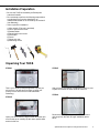
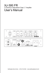
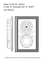
Model: THOR IW—SUB10
In-Wall 10” Subwoofer with 10” SLAPS
User Manual
Earthquake Sound Corp. | (510) 732-1000 | U.S. Toll Free: (800) 576-7944 | www.earthquakesound.com
Table of Contents
Introduction...............................................................3
Safety Instructions....................................................3
Unpacking System Components..............................4
System Installation Considerations..........................4
Connection Tips........................................................4
THOR Features........................................................4
What Your THOR Comes With.................................4
Installation Preparation.............................................5
Unpacking Your THOR.............................................5
Taking Off THOR’s Grille..........................................6
Connecting Your THOR............................................6
Installing Your THOR................................................8
Assembling the Custom Grille................................ 9
Specifications..........................................................11
5 Year Limited Warranty Guidelines.......................12
S
O
U
N
D
The Sound That Will Move You
Earthquake Sound Corporation
2727 McCone Avenue
Hayward, CA 94545
Tel: 510-732-1000
Fax: 510-732-1095
Customer Support
[email protected]
Tel: 800-576-7944
Fax: 510-732-1095
© 2010 Earthquake Sound Corporation. All rights reserved.
This document should not be construed as a commitment on the part of Earthquake Sound Corporation. The
information is subject to change without notice. Earthquake Sound Corporation assumes no responsibility for
errors that may appear within this document.
2
Earthquake Sound Corp. | (510) 732-1000 | www.earthquakesound.com
Introduction
Simply put, the THOR is the only in-wall subwoofer that
sufficiently provides bass to your home theater system.
The THOR remains stable and maintains next to zero
resonance because the user can bolt the THOR directly to
the studs from the front of the unit. This locks the THOR into
the structure of the home. Earthquake engineers also
added four dog ear fasteners for added sheet rock support.
There are two inches peak-to-peak out of a standard 16”
stud gap.
Arguably, the IW-SUB10’s best feature is the SWS
subwoofer. The SWS driver has an amazing 10” diameter
but a mounting depth of only 3 3/4”. In addition, the
impressive excursion is almost the same as the mounting
depth. While other in-wall subs struggle to maintain a good
30Hz, THOR will go all the way down to 19Hz and counting.
By including a passive radiator in the design, Earthquake
engineers maximized the small amount of given air space.
This style of enclosure also helps deliver a very clean and
deep impact bass. THOR’s back-box is constructed with
extra thick high-temperature PVC and is reinforced from
front to back all the way through the cabinet. Three
methods of reinforcement designs ensure the THOR’s
prolonged strength, durability, and maximum dampening
capability. The first is the front to back bridges that surround the drivers. At these points the cabinet is most
vulnerable to flexing and warping over time. Not the THOR.
THOR’s bridges are locked using the mounting screws and
can literally be stood on top of by a 200 pound man. Fiber
fill was also used for added resonance protection. And last
but not least, crisscrossed ribs across the bottom of the
enclosure make this in-wall enclosure the strongest and
most durable. This type of internal bracing and attention to
detail is only used in the IW-SUB10 and only at
Earthquake.
Safety Instructions
Safety First
This documentation contains general safety, installation,
and operating instructions for the THOR In-Wall SUB10.
It is important to read this user’s manual before
attempting to use this product. Pay particular attention
to the safety instructions.
Symbols Explained:
Appears on the component to indicate
the presence of uninsulated,
dangerous voltage inside the
enclosure – voltage that may be
sufficient to constitute a risk of shock.
Calls attention to a procedure,
practice, condition or the like that, if
not correctly performed or adhered to,
could result in injury or death.
Calls attention to a procedure,
practice, condition or the like that, if
not correctly performed or adhered to,
could result in damage to or
destruction of part or all of the product.
Note:
Calls attention to information that is
essential to highlight.
1)
Read these instructions in their entirety.
2)
Store this manual and packaging in a safe place.
3)
Heed all warnings.
4)
Follow instructions (do not take shortcuts).
5)
Do not use this apparatus near water.
6)
Clean only with a dry cloth.
7)
Do not block any ventilation openings. Install in
accordance with the manufacturer’s instructions.
8)
Do not install near any heat sources such as
radiators, heat registers, stoves, or other
apparatuses that produce heat.
9)
Do not defeat the safety purpose of the polarized or
grounding-type plug. A polarized plug has two
blades with one wider than the other. The
grounding-type plug has two blades and a third
grounding prong. The wide blade or the third prong
is provided for your safety. If the provided plug
does not fit into your outlet, consult an electrician
for replacement of the obsolete outlet.
10) Protect the power cord from being walked on or
pinched, particularly at plugs, convenience
receptacles, and the point where they exit from the
apparatus.
11) Only use attachments and accessories specified by
the manufacturer.
Specifications are subject to change without notice.
3
Safety Instructions (continued)
Connection Tips
12)
Use only a compatible rack or cart for the final
resting position.
• Keep all power cords away from all signal cables to
prevent humming from induced noise.
13)
Unplug this apparatus during lightning storm or
when unused for a long period of time.
14)
Refer all servicing to qualified service personnel.
Servicing is required when the apparatus has been
damaged in a way such as: power-supply cord or
plug is damaged, liquid has been spilled or objects
have fallen into the apparatus, the apparatus has
been exposed to rain or moisture, does not operate
normally, or has been dropped.
• Choose reliable signal cable cords (Earthquake Sound
also specializes in high performance RCA cables and
patches).
15)
To reduce the risk of fire or electric shock, do not
expose this apparatus to rain or moisture.
• All speaker wires that are ran through the walls should
be twisted type to reduce potential hum noise pick-up.
• Label both ends of all wires with the corresponding
room location.
• It is best to use a grounded electrical outlet to power
the amplifier. Lack of input ground reference could be
unsafe. Consult with your electrical contractor about
proper grounding.
Unpacking System Components
• Keep the original carton and packing materials for
future shipment or storage.
• Check for any visual signs of damage. If you
encounter any concealed damage, consult your
Earthquake Sound dealer before proceeding with unit
installation.
• Retain the sales receipt as it establishes the duration
fo the limited warranty and provides information for
insurance purposes.
System Installation
Considerations
There are several factors to consider before installing
Earthquake Sound’s THOR in-wall SUB-10.
THOR Features
•
•
•
•
•
•
•
•
•
•
SWS (Shallow Woofer System)
300-watt driver
2 inch Excursion
SLAPS (Symmetrically Loaded Audio Passive System)
Extra thick high temperature PVC enclosure
Back bridges that surround drivers
Reinforced back box
Crisscrossed ribs across the bottom of enclosure
Dog ear clamps for added stability
Bolts directly to 2x4 studs so no need to hassle with
brackets
• Spring loaded speaker terminals
• 3 grille options for ultimate customization
• What are the intended listening zones?
• What system options and accessories might be
required for features such as local sources, etc.?
• From where in each zone will the listener prefer to
control the system? Where will the remote gains be
located? Where will the speakers be located?
• Where will the source equipment be located?
This triangle, which appears on your component,
alerts you to the presence of uninsulated,
dangerous voltage inside the enclosure voltage that may be sufficient to
constitute a risk of shock.
4
CAUTION
RISK OF ELECTRIC SHOCK
DO NOT OPEN
Your THOR Comes With:
•
•
•
•
•
•
1 In-Wall SUB10 (THOR)
1 metal mesh grille
2 grille frames for custom fabric to match your décor
16 mounting screws
1 Allen wrench to install the logo screw
1 SWS logo
This triangle, which appears on your component,
alerts you to important operating and
maintenance instructions in this
accompanying literature.
Earthquake Sound Corp. | (510) 732-1000 | www.earthquakesound.com
Installation Preparation
• Be sure the THOR is installed by an Earthquake
authorized installer
• Do not attempt to perform the following steps without
a professional (Any product installed by an
unauthorized installer is not covered by the Limited 5
Year Warranty)
• Tools required for installation:
1) Allen wrench (This tool is provided)
2) Drill or power screw driver
3) Rubber Mallet
4) Razor blade or box cutter
5) Stud finder
6) Pencil
7) Sheet rock saw
8) Measuring device
Unpacking Your THOR
STEP#1
STEP#3
This is your THOR in-wall packaged the way that you
will receive it. We will start from here, to begin your
journey into the world of true in-wall subwoofer
technology.
After you have successfully unloaded the THOR, be sure
to place all contents of carton aside for later use.
STEP#4
STEP#2
Open your carton from the top as shown and either pull
out from the top or carefully flip the carton upside down
and let it slide out.
Remove the foam, plastic protection and two custom
grille rings from the back to begin installation procedures.
Specifications are subject to change without notice.
5
Taking Off THOR’s Grille
Connecting Your THOR
STEP#1
Your are now ready to prepare the sub for installation.
Carefully remove the logo from the grille to expose the
fastener hex nut.
Earthquake Sound’s XJ-300FR
amplifier is recommended for the use of one
THOR. The XJ-300FR amplifier is a 300watt amplifier and can be used as a mono
block, a 2 channel amplifier, or bridged for a
2.1 channel amplifier.
STEP#2
Using the provided allen wrench, remove the fastener
nut. Make sure you perform these steps before trying to
remove the grille (you will damage the grille otherwise).
STEP#3
Now to remove the grille you simply use your fingers to
push out the prongs from the back side of the unit. Push
out all prongs and the grille will simply fall out.
Earthquake Sound’s XJ-600R amplifier is
recommended for the use of two THORs.
The XJ-600R is a 600-watt, 1 channel, rack
mountable amplifier. In this instance, the
two THORs are parallelly wired.
STEP#4
HI-LEVEL
You have now successfully removed the grille and are
ready to begin preparing the wall for installation.
6
Earthquake Sound Corp. | (510) 732-1000 | www.earthquakesound.com
XLR
CH2 INPU T
R
+
-
+ -
RCA
+ -
HI-LEVEL
SPEAKER OUTPUT
110-120V
CH1 INPUT
12V DC
TRIGGER
IR
INPUT
220-240V
110-120V~/60Hz 110-120V, FUSE T6.3AL/250V
220-240V~/50Hz 220-240V, FUSE T3.15AL/250V
Specifications are subject to change without notice.
7
Installing Your THOR
STEP#1
STEP#3
Note:
These pieces are sheet rock
stabilizers, not brackets.
To begin you will need to locate the empty grille frame.
Use your stud finder to locate the studs (if you’re not
retrofitting). Using the empty frame, trace your cut line
with a pencil. Once you are satisfied with your cut line,
begin your cut using the sheet rock saw.
In the first image furthest to the left you’ll notice the
fastener in it’s neutral position– this is how it is packed.
You will need to turn all fasteners outward so that they
can be clamped to the sheet rock. You will tighten them
from the front once you have fastened the THOR to the
studs.
STEP#2
STEP#4
Note:
Accuracy of stud distance may vary
from frame to frame. It will depend
on the quality of the construction
work.
When the cutout is complete, it should look similar to the
image. Most of the work performed here is installer
common sense, please use it.
Once you have fed all wiring and connected it, slip the
THOR in the wall making sure that the sheet rock
stabilizers are in the correct position.
Begin placing screws inside holes directly into the stud
from the front. Once you have inserted all screws snugly
and securely, tighten the fasteners.
8
Earthquake Sound Corp. | (510) 732-1000 | www.earthquakesound.com
Assembling the Custom Grille
STEP#5
STEP#1
Cut your desired cloth two inches bigger than the frame
on all sides. We have provided cloth that can be used,
but feel free to use different colors or textures.
This procedure is extremely important: Tighten the
dogears by fastening the screws which are located at
the top of the active driver and the bottom of the passive
driver. If you forget to do this the sheet rock will not be
secured and the fasteners will be loose and will rattle.
STEP#6
Make sure that you have two inches of excess cloth
around all sides of the frame.
STEP#2
Cut your desired cloth, two inches bigger than the frame
on all sides. Remember that this is a custom grille so
whatever color or texture of cloth you choose, it will work
for your application.
STEP#3
Congratulations! You have successfully installed the
world’s most effective, efficient and down right loud inwall subwoofer ever made. The grille that you use is
totally up to you and can be matched to fit any decor.
(See following pages for custom cloth grille instructions).
Wrap cloth over prongs, make a small incision on cloth
over prong and push prong through cloth. Complete this
process with every prong on the frame.
Specifications are subject to change without notice.
9
Assembling the Custom Grille
(continued)
STEP#4
STEP#8
Wrap cloth around frame and put into place with
provided security ring.
This is what the inside of your grille should look like.
Pouring a quick drying glue over the ring and in the
space around where the cloth is will add more support
and provide a hard shell.
STEP#5
STEP#9
Once you have the cloth in place with security ring push
the ring enough to keep in place, though the groove with
cloth underneath.
STEP#6
Now that you have pressed the security ring in by hand,
use your rubber mallet to finish securing it completely in
the gap.
This is what your finished product should look like on
and off of the sub.
STEP#10
When you have completed the project you simply push
the grille into the front of the in-wall subwoofer gently
(use the rubber mallet if needed).
STEP#7
With your security ring in place you can begin cutting
excess cloth from the inner ring. Use extreme caution if
you choose to use a straight razor instead of a box
cutter or scissors.
10
Earthquake Sound Corp. | (510) 732-1000 | www.earthquakesound.com
Specifications
Woofer:
10” (254mm) with 2½” excursion patented design
10” SLAPS Passive Radiator
Power Rating:
50-800 Watts
RMS Power Rating:
400 Watts
Frequency Response:
20Hz-160Hz
Sensitivity:
89dB
Impedance:
4
Dimensions (HxWxD):
28” x 18 5/8” x 3 3/4” (711mm x 473mm x 95mm)
Cut out dimension (HxW):
24” x 13 3/4” (610mm x 349mm)
Mounting depth:
3 3/4” (95mm)
Finish:
white/paintable, custom grille options included
Specifications are subject to change without notice.
11
5 Year Limited Warranty Information
Earthquake warrants the original purchaser that all Factory Sealed New Audio Products be free from defects in material
workmanship, under normal and proper use, for a period of five (5) years from the date of purchase (as shown on the original sales receipt
with the serial number affixed/written on it).
The five (5) years warranty period is valid only if the product is properly installed by an Earthquake authorized party, and the
warranty registration card is properly filled out and sent to Earthquake Sound Corporation. If the product is installed by a non-authorized
party, a ninety (90) days warranty period applies.
(A) Five (5) years limited warranty plan coverage guidelines:
• First year: Earthquake pays for labor, parts, and ground freight (only in the U.S. mainland, not including Alaska and Hawaii) back
to the customer.
• Second year: Earthquake pays for labor and parts only, customer must pay freight both ways.
• Third, fourth, and fifth year: Earthquake pays for labor only. Customer must pay for parts and freight both ways.
(B) Warning:
Products (sent for repair) that are tested by Earthquake technicians and deemed to have no problem, will not be covered by the five
(5) years limited warranty. Customer will be charged a minimum of one (1) hour of labor (ongoing rates) plus shipping back to the customer.
(C) Earthquake agrees to repair or replace, at our option, all such defective products/parts subject to the following provisions:
• Defective products/parts have not been altered or repaired by other an Earthquake factory approved technician.
• Products/parts are not subjected to negligence, misuse, improper use, aor accident, damaged by improper line voltage, used
with incompatible products, or have its serial number or any part of it altered, defaced, removed, or have been used in anyway
that is contrary to Earthquake’s written instructions.
(D) Warranty Limitations:
Earthquake warranty does not cover products that have been modified and/or abused, including but not limited to the following:
• Damages to unit cover and finish due to misuse, abuse, or improper use of cleaning materials/methods.
• Bent casing, damaged finish on casing due to abuse, misuse, or improper frame or broken connections.
• Fading, deterioration of components and finish due to improper exposure to elements.
• Burnt tracers of PCB.
• Product/part damaged due to poor packaging or abusive shipping conditions.
• Subsequent damage to other products.
A warranty claim will not be valid if the warranty registration card is not properly filled and returned to Earthquake with a copy of the sales
invoice.
(E) Service Request:
To receive product(s) service, contact Earthquake Sound’s service department at (510) 732-1000 and request an RMA number
(Return Material Authorization), item(s) shipped without a valid RMA number will be refused. Make sure you provide us with your complete
and correct shipping address, a valid phone number, and a brief description of the problem you are experiencing with the product. In most
cases, our technicians might be able to resolve the problem over the phone, thus eliminating the need to ship the product.
(F) Shipping Instructions:
Product(s) must be packaged in its original protective box(es) to minimize transport damage. Shipper claims regarding item(s)
damaged in transit must be presented to the carrier. Earthquake Sound Corporation reserves the right to refuse improperly packed
product(s). A copy of original sales receipt must accompany product(s) returned for service. We encourage you to include a written
description fo the problem inside the package. Ship to:
Earthquake Sound Corp.
2727 McCone Avenue
Hayward, CA 94545 USA
You are responsible for the cost of shipping the product to Earthquake Sound Corporation.
(G) Disputes Resolution:
All disputes, between clients and Earthquake Sound Corporation, resulting from the five (5) years limited warranty policy must be
resolved according to the laws and regulations of the county of Alameda, California.
Sound That Will Move You
Earthquake Sound reserves the right to amend details of the specifications without notice.
© Copyright Earthquake Sound Corporation
Earthquake Sound Corporation
2727 McCone Avenue, Hayward CA, 94545
Phone: (510) 732-1000 U.S. Toll Free: (800) 579-7944 Fax: (510) 732-1095