1
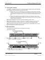
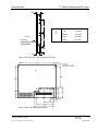
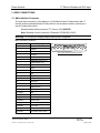
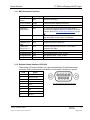
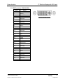
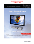
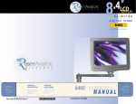
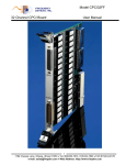
ELECTRONIC REVISION CONTROLLED Document Number: 102031 Rev B Rosen Aviation 17” SlimLine Display with DVI Input Technical Manual, 17” SlimLine Display with DVI Input © 2008 by Rosen Aviation, LLC All Rights Reserved The information contained herein is proprietary to Rosen Aviation, LLC. No part of this publication may be reproduced, transmitted, transcribed, stored in a retrieval system, or translated into any language in any form by any means without written authorization from Rosen Aviation, LLC, except as allowed under copyright laws. Disclaimer of Liability The information contained in this document is subject to change without notice. Because we are continually improving and adding features to our products, Rosen Aviation, LLC reserves the right to change specifications without prior notice. Rosen Aviation, LLC shall not be liable for technical or editorial errors or omissions contained herein. Rosen Aviation, LLC 1020 Owen Loop South Eugene, OR 97402 541.342.3802 888.668.4955 Fax: 541.342.4912 www.rosenaviation.com Document Number: 102031 Template: 4.2-3-6-FM; Revision D; 13 March 2008 Revision: Date: TBD B Page 2 of 18 Rosen Aviation 17” SlimLine Display with DVI Input Contents 1. INTRODUCTION AND DISPLAY OVERVIEW .................................................................4 1.1. Unpacking .................................................................................................................. 4 2. INSTALLATION GUIDELINES .........................................................................................4 2.1. Cooling and Ventilation .............................................................................................. 5 2.2. Mounting Options....................................................................................................... 5 3. VIDEO CONNECTIONS ....................................................................................................7 3.1. Main Interface Connector .......................................................................................... 7 3.2. Main Connector Functions ......................................................................................... 8 3.3. External Control Interface (0300-402)........................................................................ 8 3.4. DVI Connector ........................................................................................................... 9 3.5. DIP Switch Option Selection .................................................................................... 10 3.6. Auto-Detect .............................................................................................................. 10 3.7. Constant Ground — No DVI .................................................................................... 10 3.8. Momentary Ground — No DVI ................................................................................. 11 3.9. Manual Mode — DVI ............................................................................................... 11 3.10. Automatic Power-Up .............................................................................................. 11 3.11. Membrane Switch Enable ...................................................................................... 11 4. OPERATION ................................................................................................................... 12 4.1. Front Switch Panel Features ................................................................................... 12 4.2. On Screen Display (OSD) Main Menu ..................................................................... 13 4.3. Picture Submenu ..................................................................................................... 13 4.4. OSD Submenu......................................................................................................... 14 4.5. Utility Submenu........................................................................................................ 14 4.6. Auto Submenu ......................................................................................................... 14 4.7. Exit Submenu .......................................................................................................... 15 5. HOT KEYS ...................................................................................................................... 15 6. TECHNICAL REFERENCES AND SUPPORT ............................................................... 16 7. DO-180E QUALIFICATIONS .......................................................................................... 17 7.1. Specifications........................................................................................................... 17 8. REVISION HISTORY ...................................................................................................... 18 Document Number: 102031 Template: 4.2-3-6-FM; Revision D; 13 March 2008 Revision: Date: TBD B Page 3 of 18 17” SlimLine Display with DVI Input Rosen Aviation 1. INTRODUCTION AND DISPLAY OVERVIEW This manual describes how to install the Rosen 17” SlimLine Display with DVI Input onto your aircraft. It contains everything you need to know to wire the display and confirm that it is functioning correctly. The display receives Composite, Analog RGB, and DVI video input. DVI input is shown as Digital RGB in the on-screen display when switching between video sources. Note: Only trained and qualified personnel should perform installation and service. 1.1. Unpacking Parts shipped with the 17” SlimLine Display with DVI Input: Outline & Installation Drawing 17” Display with DVI Input Main Interface Connector kit (P/N 0300-021) Optional equipment sold separately: External 7-button Controller (P/N 0300-402) shipped with Remote Controller Technical Information (P/N 100434) DVI Connector Kit (P/N 0300-029) For more information about Outline & Installation drawings, please contact Rosen Aviation Customer Service at 541.342.3802. 2. INSTALLATION GUIDELINES There are several ways to connect the 17” Display with DVI Input to an aircraft’s entertainment system. Use the pinout descriptions on page 2 of the Outline & Installation drawing to assist in the wiring process. Pay close attention to the pinout information while completing wiring connections. Note: This display is for entertainment purposes only; connect to the non-critical power bus. Drawings are provided to assist in the installation process. Pay close attention to dimensions and rotations when considering installation requirements. Touching the LCD with excessive force may leave pressure spots that show in video display. Handle with care. Document Number: 102031 Template: 4.2-3-6-FM; Revision D; 13 March 2008 Revision: Date: TBD B Page 4 of 18 Rosen Aviation 17” SlimLine Display with DVI Input 2.1. Cooling and Ventilation The display is cooled by the flow of air, or natural convection. Special care must be taken with the installation to provide a proper environment for air flow. Display vents: The unit is designed with vent openings on the top, bottom, and rear surfaces. The entire top vent, and either the entire bottom or entire rear vent must be unobstructed for a minimum of one (1) inch. The vents must also be ducted to free air. Ducting: The installation must provide for an inlet duct (at bottom or rear), and an exhaust duct at the top. Each of these ducts must have a minimum of four (4) square inches of cross-sectional area. Note: Display backlight will shut down if internal temperature reaches 140° F. Note: Each mounting hole includes a 10-32 screw. To install the display, remove only the screws that will be used to install the display. Do not remove the 4-40 flathead screws. Note: Application requires listed connector backshell (Positronic D37000GEO-1023.5) due to space constraints and 21WA4 combo connector. 2.2. Mounting Options This display can be mounted from any combination of two sides. (Dimensions in inches) Figure 1 Top view with mounting holes Figure 2 Bottom view with mounting holes Document Number: 102031 Template: 4.2-3-6-FM; Revision D; 13 March 2008 Revision: Date: TBD B Page 5 of 18 17” SlimLine Display with DVI Input Rosen Aviation 1.49 4.50 Warning! ! Front 6x 10-32 MOUNTING HOLES (BOTH SIDES) 4.50 Maximum screw penetration depth: Top .75 inches Bottom .75 inches Sides .75 inches Rear .50 inches 1.86 1.12 Figure 3 Side view with mounting holes (3 per side) Figure 4 Rear view with mounting holes Document Number: 102031 Template: 4.2-3-6-FM; Revision D; 13 March 2008 Revision: Date: TBD B Page 6 of 18 17” SlimLine Display with DVI Input Rosen Aviation 3. VIDEO CONNECTIONS 3.1. Main Interface Connector The main input connector on this display is a 21W4 Male Combo D-subminiature with 17 size-20 contacts (standard density D-sub) and four size-8 coaxial contacts, mounting in a size-4 D-subminiature shell. Recommended mating connector: ITT Cannon: (P/N 9000879). Note: Backshell of main connector is Positronic D37000GEO-1023.5. Warning! Do not plug or unplug display while power is applied! Main Interface Connector Pin # Display Signal 1 28V return 2 +28VDC 3 IR +5V 4 IR signal 5 Reserved 6 RGB/video select (TTL) 7 Status output (TTL) 8 Hsync 9 Vsync 10 28V return 11 28V 12 IR ground 13 Computer sync ground 14 Reserved 15 Digital ground 16 Digital ground 17 Digital ground A1-signal Red A1-shield Red return A2-signal Green A2-shield Green return A3-signal Blue A3-shield Blue return A4-signal Composite video A4-shield Composite video return Document Number: 102031 Template: 4.2-3-6-FM; Revision D; 13 March 2008 Rear view of the Main Interface Connector Revision: Date: TBD B Page 7 of 18 17” SlimLine Display with DVI Input Rosen Aviation 3.1.1. Main Connector Functions Signal Input/Output Description +28V, 28V Return Input Aircraft power supply IR +5V, IR GND Output Power for optional External IR receiver IR Signal Input IR receiver signal input RGB/Video Select Switch Input TTL level input. Used to select which input (RGB or Composite) is displayed. Method of selection set by DIP switches. Refer to DIP Switch Option Selection on page 10. Status Output Output TTL level output indicates display is powered on when logic High (Max. current draw is 10 milliamps) H-Sync, V-Sync Input RGB graphics input, TTL level Computer Sync GND Input Reference ground for RGB sync Digital GND, pins 15, 16, 17 Input Common digital ground connection, connected to Computer sync GND A1 Signal/Shield Input Red graphics input, 1 Vpp, 75 ohm A2 Signal/Shield Input Green graphics input, 1 Vpp, 75 ohm A3 Signal/Shield Input Blue graphics input, 1 Vpp, 75 ohm A4 Signal/Shield Input Composite video input, 1 Vpp, 75 ohm 3.1.2. External Control Interface (0300-402) The external VIP control interface is a 9-pin standard density D-subminiature male connector. Each function can be activated by a momentary connection to ground. Pin # Signal 1 Power On/Off 2 Source Select 3 NC 4 Up 5 Down 6 Menu Select 7 Left 8 Right 9 Ground Document Number: 102031 Template: 4.2-3-6-FM; Revision D; 13 March 2008 Rear view of the External Control Connector Revision: Date: TBD B Page 8 of 18 17” SlimLine Display with DVI Input Rosen Aviation 3.1.3. DVI Connector (P/N 0300-029) Pin # Signal 1 Data 2- 2 Data 2+ 3 Data 2 RTN 4 Reserved 5 Reserved 6 Reserved 7 Reserved 8 Reserved 9 Data 1- 10 Data 1+ 11 Data 1 RTN 12 Reserved 13 Reserved 14 VCC 15 Reserved 16 H Plug 17 Data 0 - 18 Data 0 + 19 Data 0 RTN 20 Reserved 21 Reserved 22 Clock RTN 23 Clock + 24 Clock - C1 Reserved C2 Reserved C3 Reserved C4 Reserved C5 Reserved Document Number: 102031 Template: 4.2-3-6-FM; Revision D; 13 March 2008 Rear view of the DVI Connector Revision: Date: TBD B Page 9 of 18 17” SlimLine Display with DVI Input Rosen Aviation 3.2. DIP Switch Option Selection Use DIP switches located near the input connectors. See Section 3.2.1 (below) for detailed descriptions. Operation is as follows: SWI SW2 SW3 SW4 Function On Off - - Constant Ground – No DVI Off On - - Momentary Ground – No DVI On On - - Auto-detect (RGB) Off Off - - Momentary Ground – DVI - - Off - Display defaults to Off (Auto Off) - - On - Display defaults to On (Auto On) - - - On Front Switch Panel Enabled - - - Off Front Switch Panel Disabled The display may be configured to several options through the setting of DIP switches located near the input connectors. The DIP switch settings are detected when 28 volts are applied, and each time the power button is pressed to turn on the display. 3.2.1. DIP Switch Function Descriptions Note: DVI video is also shown as Digital RGB when switching between video sources. Auto-Detect When the RGB/Video Select pin (pin 6 of the 21WA4 combo connector) is connected to ground, DVI is selected for display. When the RGB/Video Select pin is not connected to ground, Composite is selected for display. In this mode, when either Composite or Digital RGB (DVI) is selected for display via the RGB/Video Select pin and an analog RGB signal becomes present, the display will automatically switch to the analog RGB signal. It will return to whatever source was selected after the analog RGB signal is removed. The Source button located on the front panel membrane switch and optional external switch controller will be locked out. Constant Ground — No DVI This mode uses the Source Select discrete input to switch between RGB and Composite video inputs only. This mode uses a SPST (single-pole, single-throw) external rocker switch connected between ground and RGB/Video Select (pin 6 of the 21WA4 combo connector). When the RGB/Video Select pin is connected to ground, the display will switch to the RGB input whether an RGB signal is present or not. When the RGB/Video Select pin is not connected to ground, the display will switch to the Composite Video input whether a video signal is present or not. The Source button located on the front panel membrane switch and optional external switch controller will be locked out. Document Number: 102031 Template: 4.2-3-6-FM; Revision D; 13 March 2008 Revision: Date: TBD B Page 10 of 18 Rosen Aviation 17” SlimLine Display with DVI Input Momentary Ground — No DVI This mode uses the Source Select discrete input to toggle between RGB and Composite video inputs only, based on a momentary ground. This mode uses a SPST external momentary switch between ground and the RGB/Video Select (pin 6 of the 21WA4 combo connector). Each time the switch is pressed, the display will switch back and forth between the Analog RGB and Composite Video inputs whether a signal is present or not. The Source button located on the front panel membrane switch and an optional external switch controller can also be used to switch between the RGB and Composite Video inputs. Momentary Ground — DVI This uses the Source Select discrete input to toggle between Analog RGB, Digital RGB (DVI), and Composite video based on the momentary ground input. The Source button located on the front panel membrane switch and optional external switch controller can be used to switch between the RGB, DVI, and Composite Video inputs. Automatic Power-Up SW3 On: The display will come on as soon as 28-volt power is applied. SW3 Off: The display stays off when 28-volt power is applied. The power button on the front panel membrane switch or the optional external switch controller must be pressed to turn on the display. Membrane Switch Enable . SW4 On: Front panel membrane switch is enabled. SW4 Off: Front panel membrane switch is disabled Document Number: 102031 Template: 4.2-3-6-FM; Revision D; 13 March 2008 Revision: Date: TBD B Page 11 of 18 17” SlimLine Display with DVI Input Rosen Aviation 4. OPERATION 4.1. Front Switch Panel Features To operate the 17” SlimLine display, use the front switch panel buttons shown below. (External controller or IR remote control options are available separately.) Power Status LED Menu Select Source Power Feature How it Works Power Status LED When the LED is green, the display is on. When the LED is red, the display is in Standby Mode. Menu/Sel Press to view the OSD Main Menu and to select the highlighted Main Menu option. Source Press to toggle the video source between Analog RGB, Digital RGB (DVI), and Composite video. Note: This only functions when DIP switch is set to Momentary Ground or Manual mode. Press to select a menu option or to increase or decrease a value. Power Press to power the display on or off. Document Number: 102031 Template: 4.2-3-6-FM; Revision D; 13 March 2008 Revision: Date: TBD B Page 12 of 18 17” SlimLine Display with DVI Input Rosen Aviation 4.2. On Screen Display (OSD) Main Menu The On Screen Display (OSD) provides a set of menus that enable you to adjust or view display features. Main Menu selections lead to submenus with additional choices. Press the Menu/Select button on the switch panel to open the Main Menu. Figure 5 Composite Main Menu Figure 6 RGB Digital (DVI) Main Menu To switch to different Main Menus (OSD, Utility, Auto), press the ◄► buttons on the front switch panel. To highlight a submenu, press the ▼ button on the switch panel. When submenus are highlighted, press the ◄► buttons to adjust the values. To return to the Main Menu, press the ► button on the switch panel to highlight Return in the submenu. To exit Main Menu, press the ► button until Exit is highlighted and then press the Menu Select button. Note: It takes five seconds for changes to be stored into memory. 4.3. Picture Submenu Menu Option How it Works Brightness Adjusts picture brightness Contrast Adjusts picture contrast Hue (Composite Only) Shifts the color balance or tint Saturation (Composite Only) Intensifies the image colors Filter Select (Composite Only) Increases the clarity of the picture Phase Removes noise in Analog RGB mode Frequency Adjusts the picture size in Analog RGB mode H Position Adjusts horizontal position adjustment V Position Adjusts vertical position Sharpness Adjusts picture sharpness Return Returns OSD to the Main Menu These options gray out and are not available with the RGB/DVI mode Note: Phase, Frequency, H Position, and V Position appear only in analog RGB/DVI mode. Document Number: 102031 Template: 4.2-3-6-FM; Revision D; 13 March 2008 Revision: Date: TBD B Page 13 of 18 17” SlimLine Display with DVI Input Rosen Aviation 4.4. OSD Submenu Menu Option How it Works H Position Adjusts OSD horizontal position V Position Adjusts OSD vertical position OSD Timeout Adjusts time in which OSD turns off if left alone Return Returns OSD to the Main Menu 4.5. Utility Submenu Menu Option How it Works Freeze Frame Freezes picture frame Reset Returns options to default settings Special Filter Slow/fast motion picture filter Color Temperature Adjusts color in Composite and DVI modes Information Shows the operating status of the display Return Returns you to Main Menu This option grays out and is not available with the RGB/DVI mode Note: Digital RGB mode (DVI/1080p) will not display correctly with special filter enabled. Special filter can only be enabled in composite mode. Document Number: 102031 Template: 4.2-3-6-FM; Revision D; 13 March 2008 Revision: Date: TBD B Page 14 of 18 17” SlimLine Display with DVI Input Rosen Aviation 4.6. Auto Submenu Menu Option How it Works Automatically adjusts image size in RGB modes Auto 4.7. Exit Submenu Menu Option How it Works Closes the screen. To exit menu, press ◄. Exit 5. HOT KEYS Hot keys are a quick way of adjusting brightness, contrast, picture-in-picture (PIP), and the scaling modes without going through the OSD menu. To activate the hot keys, simply press the ▲▼buttons on the switch panel to cycle through these modes, then use ►◄ buttons to change values. The hot keys will not work if an OSD menu is open. Hot Key Option Scaling mode Picture-in-Picture (PIP) [RBG/DVI only] Document Number: 102031 Template: 4.2-3-6-FM; Revision D; 13 March 2008 How it Works The scaling mode will adjust the picture depending on the type of formatted DVD disc you are using. Note: If picture looks stretched, adjust scaling mode. Fill All Fill Aspect Ratio One To One Letterbox 16:9 fill (tall) [Composite Only] Anamorphic [Composite Only] The small screen in the upper left-hand corner will display composite video in small, medium, and large PIP when in RGB/DVI modes. Note: PIP will only function correctly with progressive video signals. It will not function with interlacing video signals (480i/1080i). Revision: Date: TBD B Page 15 of 18 17” SlimLine Display with DVI Input Rosen Aviation 6. TECHNICAL REFERENCES AND SUPPORT If the display does not function properly, refer to the following troubleshooting table for symptoms and possible solutions before contacting Rosen field support. Always use an oscilloscope to verify the video signal Always use a multimeter to verify voltages Check actual results against the requirements described in this manual Problem No Video Possible Solutions Verify that the video source is on and has a tape or DVD installed. Verify that a signal is reaching the display by using an oscilloscope or another display. Verify that the display is turned on (LED is green). Verify that the pinout is correct. Verify that the video input (Analog RGB/DVI/Composite) and video standard (NTSC/PAL/SECAM) match your application. Screen is Black Verify that the display is receiving power. Verify that the pinout is correct. Verify that the video source is on and has a tape or DVD installed. Verify all connections. Screen is Blue Verify that a signal is reaching the display by using an oscilloscope or another display. Verify that the pinout is correct. Verify that the video source is on and has a tape or DVD installed. Color is Out of Adjustment Refer to the OSD Main Menu options described on page 13. Image Flickers Verify that the signal cable is secure. Verify that the vertical frame frequency is 75 Hz or less. If using the display with a PC in Windows, go to Control PanelDisplay Properties and change the Display Control Panel to 60 Hz to achieve the best performance. Image is distorted Verify pinouts. Verify that a signal is reaching the display by using an oscilloscope or another display. Examine the display for pinched or damaged cables. Document Number: 102031 Template: 4.2-3-6-FM; Revision D; 13 March 2008 Revision: Date: TBD B Page 16 of 18 17” SlimLine Display with DVI Input Rosen Aviation 7. DO-180E QUALIFICATIONS DO-160E Test criteria to which we test the 1700-003 series displays Description DO-160E Section DO-160E Category Temperature and Altitude 4.0 A1 Temperature Variation 5.0 C Humidity 6.0 A Operational Shock & Crash Safety 7.0 B Vibration 8.0 SB Explosion Proofness 9.0 N/A Waterproofness 10.0 N/A Fluids Susceptibility 11.0 N/A Sand & Dust 12.0 N/A Fungus Resistance 13.0 N/A Salt Spray 14.0 N/A Magnetic Effect 15.0 Z Power Input 16.0 AB Voltage Spike 17.0 B Audio Frequency Susceptibility — Power Inputs 18.0 Z Induced Signal Susceptibility 19.0 Z Radio Frequency Susceptibility (Radiated & Conducted) 20.0 TT Emission of Radio Frequency Energy 21.0 B Lightning Induced Transient Susceptibility 22.0 N/A Lightning Direct Effects 23.0 N/A Icing 24.0 N/A Electrostatic Discharge 25.0 A 7.1. Specifications Size 13.37 x 10.71 inches [339.6 x 272.0mm] Resolution 1280 w x 1024 h Viewing Angle (U/D/L/R) 80/80/80/80° Brightness 200 cd/m Contrast Ratio 400:1 min, 500:1 Typical Video Input 1Vp-p, 75 ohms Video Standards NTSC, PAL, SECAM, RS 170 Graphics Standards VGA through SXGA Document Number: 102031 Template: 4.2-3-6-FM; Revision D; 13 March 2008 2 Revision: Date: TBD B Page 17 of 18 17” SlimLine Display with DVI Input Rosen Aviation Weight 7.9 lbs ± 5% Installed Dimensions 15.32” (W) x 12.72” (H) x 1.49” (D) [389.1 mm (W) x 323.1 mm (H) x 37.8 mm (D)] Power Requirements 28V DC 40W max Operating Temperature 0ºC - 50ºC Warranty 2-year 8. REVISION HISTORY Revision Date Revision Description EC # A 11/26/08 Initial Release 08516 B TBD Update PIP information in Section 5, add note to sections 4.3 and 4.5 09250 Document Number: 102031 Template: 4.2-3-6-FM; Revision D; 13 March 2008 Revision: Date: TBD B Page 18 of 18