1
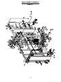
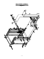
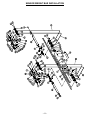
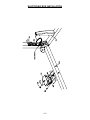
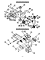
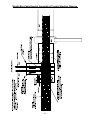
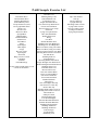
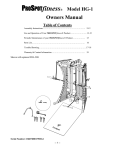
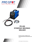
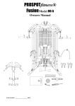
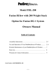
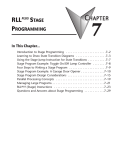
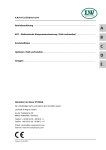
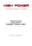
PROSPOTfitness
®
Model P-600
Owners Manual
Table of Contents
Assembly Instructions……………………..…………………………..……..2-11
Use and Operation of Your PROSPOTfitness® Product….………………..12-16
Periodic Maintenance of your PROSPOTfitness® Product……………….… 17
Parts List…………………………………………………….…………….…18-19
Trouble-Shooting……………………………………………………………..20-21
Warranty & Contact Information……………………………………….…….…22
Serial Number: 18604R00175P-600
-- 1 --
Instructions for Assembly of the ProSpotfitness® P-600
•
Before assembly, choose a safe location for your PROSPOTfitness® P-600. The PROSPOTfitness® P-600
has a footprint of approximately 6’x 6’. The barbell is approximately 7’ long. Locate your PROSPOTfitness®
P-600 away from any source of water. Do not allow any liquid to be near the machine or spilled on any
electrical part. Do not insert any object into the electrical box.
•
Approximate assembly time is 1-1/2 hours.
•
A flat area of 9’ x 9’ will be required to assemble and properly use the PROSPOTfitness® P-600.
•
You will need the following tools and a helper to complete the assembly:
•
Enclosed you will find the following tools:
•
•
•
•
•
•
•
3 mm Allen Wrench
4 mm Allen Wrench
6 mm Allen Wrench
3/16" Allen Wrench
9/16" Allen Wrench
You will need the following tools:
• 16 mm Hex Head Wrench
• 18 mm Hex Head Wrench
• Philips Screw Driver
Floor Padding, such as cardboard, to avoid scratching your floor during assembly.
•
A good pair of scissors will be helpful in separating the parts from one another while removing them from
the cartons.
•
HAND TIGHTEN all bolts. DO NOT fully tighten bolts until instructed to do so.
•
Assistance by a second person is recommended for some steps of this assembly.
•
Before assembly, separate and identify the right-sided parts from the left-sided parts. These parts are easily
distinguished by the manner in which the pre-drilled holes align with corresponding parts, or are identified by
“L“ & “R” stickers.
•
The PROSPOTfitness® P-600 uses several different lengths of bolts. Be careful to use the correct length of
bolt called for at each step of assembly. Refer to the sizing charts provided.
• WARNING: Never perform any maintenance on the ProSpotfitness®
P-600 while the Power Supply is plugged into the wall !!!
ALWAYS REMEMBER: After the initial set up of the system or after performing any
service on the unit, RESET the Computer on your ProSpot system before using it. Just unplug
the power supply from the Electronic Box, wait 30 seconds and plug back in. Resetting the
Computer allows it to recalibrate and work to its greatest efficiency.
--2--
Instructions for Assembly of the ProSpotfitness® P-600
Step #1 MAIN FRAME ASSEMBLY
1. Place the Base Rails (6,7) opposite each other in the center of the assembly area as shown in the illustration.
Place Lower Frame Cross Brace (14) between the two Base Rails (6,7) so that the side, pre-drilled holes of
the Base Rails align with the holes of the Lower Frame Cross Brace. Secure with bolt #107, flat washer
#133 and lock nut #128.
2. Place the Lower Back Base Rail (13) between the two Base Rails (6,7). Make sure the rubber grommet hole
for the Base Frame Wire Harness (143) is facing toward the back of unit. Thread the Base Frame Wire
Harness (143) sticking out of the ends of the Lower Back Base Rail (13) through the side openings of the
side Base Rails (6,7). Note: The optional ProSpotfitness® PHL-60 Hi/Low Pull can be mounted rearfacing in order to create a separate exercise station. If you wish you to mount the PHL-60 rear-facing,
make sure the rubber grommet hole for the Base Frame Wire Harness (143) is facing toward the front
of the unit when placing the Back Base Rail (13) between the two Base Rails (6,7).
3. Align the side pre-drilled holes of the Base Rails (6,7) with the holes of the Lower Back Base Rails (13).
Place right and left rear locking posts (one at a time) (4,5) onto Base Rails (6,7) by lining up holes with the
Base Rails. Ensure that holes are facing the back. Secure with bolts #106, flat washers #133 and lock nuts
#128. Plug Base Rail Wire Harness (143) into Spiral Cable (144) as shown in Diagram.
4. Place right and left Front Guide Posts (1,2) onto Base Rails (one at a time) (6,7) by lining up holes with the
Base Rails (6,7). Make sure decals and pulleys are facing forward. Attach Support Plate (3) to inside of both
right and left Guide Posts (1,2) to the Base Rails. Secure with bolts # 106, flat washers #133 and lock nuts
#128.
5. Slide the right and left Cable Head Slider Frame (15,16) onto right and left Front Guide Posts (1,2) so that
the Lock Down Pin (26) on each Cable Head Slider Frame is on the inside on the Front Guide Posts (1,2).
Install Lock Down Pin (26) by screwing it into the pre-threaded hole.
6. Attach upper Support Plate (3) to outside of both right and left Front Guide Posts (1,2). Insert two bolts #106
and two flat washers #133 through two lower holes in the upper Support Plate (3). Align the holes of the
Front Top Rail (12) with the holes of the right and left Front Guide Posts (1,2). Secure with bolts #106, flat
washers #133 lock nuts #128.
7. Attach Back Top Upright Support Plate (10) to the outside of both right and left Rear Locking Posts (4,5).
(Note: Pre-drilled holes of the Back Top Upright Support Plates are placed off center. To ensure proper
placement, position Back Top Upright Support Plate so that the holes are toward the front of the Rear
Locking Posts (4,5). (See diagram.) Insert two bolts #106 and two flat washers #133 through two lower holes
in the Back Top Upright Support Plate (10). Align the holes of the Back Top Rail (11) with the holes of the
right and left Rear Locking Posts (4,5). Secure with washer #33 and lock nut #128.
8. If the two Big Pulley Double-Groove (34) on each Upper Frame (8,9) are not pre-installed, install them at this
time. These two pulleys are placed on each end of the Upper Frames (8,9). Align each Big Pulley DoubleGroove (34) with the pre-drilled holes and secure with bolts #108, flat washers #134 and lock nuts #129.
9. If the four Upper Frame Pulleys (32) on each Upper Frame (8,9) are not pre-installed, install them at this
time. For each pulley, align pulley holes with pre-drilled holes. Place an Upper Frame Pulley Bushing (36)
on both sides of pulley and secure with bolt #108, flat washer #134, lock nut #129
10. Place the right Upper Frame (8) onto the right side of partially assembled frame so that the accessory hook
faces outward. Align pre-drilled holes on upper frame with back and front top rails (11,12). Secure with bolts
#106, two flat washers #133 and two lock nuts #128. Repeat procedure with left Upper Frame (9). Caution:
be careful not to pinch cables while inserting Upper Frames.
11. Tighten all bolts at this time.
12. At this time the barbell cables (32,33) will be hanging out of the right and left Rear Locking Posts (4,5).
Raise the barbell cables up and over the top of the double-grooved pulleys. Place them into the grooves,
taking care not to cross the cables.
13. Install Cable Keeper over the Big Pulley Double-Groove (34), using bolt #114, two flat washers #137 and
lock nut #131. Position the Cable Keeper Tube (35) between the frame. Place bolt and washers through
upper frame, through the tube and secure with lock nut on the other side of the frame.
14. Place Inspection Cover (75) on each left and right Rear Locking Posts (4,5) using #126 Phillip screws.
--3--
STEP #2 – SENSOR WEIGHT BAR INSTALLATION
1. Standing in front of the ProSpot Fitness P-600, slide one end and then the other end of the Sensor Weight
Bar (37) into the Knuckles (55,56,57). Ensure that barbell cables are not crossed or twisted. Slide the
Knuckles onto the bar until they rest snugly against the pre-installed Sensor Retaining Collars (50,51).
There is a rotation-limiting pin that protrudes from the bottom of the Sensor Weight Bar (37) that must fit
through a slot in the Knuckles as it is slid into position.
2. Install plastic Locking Sleeve (42) onto each end of the Sensor Weight Bar (37) and slide them inwards until
they rest firmly against the Knuckles (55,56,57). Tighten bolts using supplied 4mm Allen Wrench, ensuring
that the Locking Sleeve (42) securely holds the Knuckles (55,56,57) in place.
3. Install the Weight Bar Rotating Brackets (43) by sliding them onto each end of the Sensor Weight Bar (37).
Attach snap link (clip) (157).
4. Slide Olympic Adapters (38) onto each end of the barbell and secure with Weight Bar Shoulder Bolt (40),
using supplied, large, 9/16 Hex wrench to fasten the shoulder bolt.
5. Attach Spring Clips (39) to barbell.
STEP #3 – PULLEY INSTALLATION
1. Begin by installing the two Large, Single-Groove Pulley (32) into left and right Base Rails (6,7). Align pulleys
with pre-drilled holes and secure with bolt #109, flat washer #32 and lock nut #129.
2. Install two Large, Single-Groove Pulleys (32) into the left and right Guide Posts (1,2) by aligning pulleys with
pre-drilled holes and secure with bolt #109, flat washer #32 and lock nut #129.
3. Install large, Single-Groove Pulley (32) into Cable Head Slider Frame (15,16) by aligning the pulley with predrilled holes and secure with bolt #109, flat washer #32 and lock nut #129.
4. Install two small, Single-Groove Pulleys into each Cable Swivel Head Pulley Frame (31) by aligning each
pulley with the pre-drilled holes and secure with bolt #109, flat washer #32 and lock nut #129.
STEP #4 – SIDE WEIGHT PLATE HOLDER SUPPORT FRAMES
1. Attach each Side Weight Plate Holder Support Frame (66) to Upper Frame (8,9) and side Base Rails (6,7)
and secure with Backing Plate (67) and bolts #106, flat washers #133 and lock nuts #128.
2. Attach Top Weight Plate Holder (69) to each Side Weight Plate Holder Support Frame (66) in top position.
Secure with Backing Plate (67) and bolts #106, flat washers #133 and lock nuts #128. Note: The Top
Weight Plate Holder has a hole in it for optional dip station.
3. Attach Lower Weight Plate Holder (68) to Side Weight Plate Holder Support Frame (66) in two lower
positions. Secure with Backing Plate (67) and bolts #106, flat washers #133 and lock nuts #128.
STEP #5 – WEIGHT STACKS INSTALLATION
1. Remove both PWS-200 Weight Stacks (98) from their cartons and place near the P-600.
2. Insert Bottom Guide Rod Cup Holders (97) into the elevated part of the side Base Rails (6,7), as shown in
Diagram. Note: there are two different types of Guide Rod Cups. The Top Guide Rod Cup Holders have a
flat side while the Bottom Guide Rod Cup Holders are completely round. Ensure that the Bottom Guide Rod
Cup Holders are installed at this time.
3. Insert Weight Stack Guide Rods (100) into Bottom Guide Rod Cup Holders (97).
4. Add weight plates. This step is easier to perform with assistance from another person. Tilt Weight Stack
Guide Rods (100) to the side so that the weight plates can be slid onto them. Starting with the bottom #200
weight plate slide down on Guide Rods (100). Keep weight plates in order and make sure the weight
indicator numbers face inward. Repeat until all weight plates are installed. Then install top plate with
Selector Key (99) on cord facing toward the inside of the unit.
5. Slide Top Guide Rod Cup Holders (96) onto the Guide Rods (100) ensuring the flat portion of the Cup
Holders are facing each other on the inside of the weight stack.
6. Install Guide Rod Retainer Housing (95) on top of the Top Guide Rod Cup Holders (96). Position them
underneath the left and right Upper Frames and bolt into pre-threaded hole in frame using bolt #111, spring
washer #135 and flat washer #134.
--4--
7. Place Side Weight Stack Covers (73) so that the holes on the cover align with the holes on the tabs of the
Upper Frame and bottom Side Base Rails (6,7). Secure with bolts #113, flat washers #136 and nuts #130.
8. Install jam nuts (103) onto threaded portion of each Weight Stack Pulley Bracket (101). Rotate the nut until
¾” of the thread is exposed. Now install Weight Stack Pulley Brackets (101) to the top plate of the weight
stacks (98). Turn each Weight Stack Pulley Bracket until it hits the jam nut (103).
9. Install small, Single-Groove Pulley (33) into each Weight Stack Pulley Bracket (101) and secure each with
bolt #109, flat washer #134 and lock nut #129.
10. Make sure all pulley bolts are tight.
STEP #6 – CABLE INSTALLATION
1. If ball and bracket assemblies are attached to cables, disassemble and set aside.
2. Begin by screwing Side Weight Stack Cable (102) into Cable Head Slider Frame (15,16) one-half inch (½”).
3. For each left and right cable installation perform the following steps: Thread Side Weight Stack Cable (102)
over the two pulleys in the Upper Frame (8,9), then down and underneath the Weight Stack Pulley and back
up over the remaining two Upper Frame pulleys and then down to the pulley on the side Base Rail (6,7).
Next, thread the cable through the holes in the weight stack support frame on the lower base rails, then
underneath the pulley in the Front Guide Post (1,2). Go over top the large pulley in the Cable Head Slider
Frame then between the two small pulleys in the Cable Head Slider Frame (15,16). (See Diagram.)
4. Once cable is through the two small pulleys in the Cable Head Slider Frame (15,16), install ball and bracket
assembly onto the end of the cable: Slide hard, black, plastic ball into cable end and slide round ball tip of
cable into u-shaped bracket. Place Link Ring (158) into u-shaped bracket and secure assembly with bolt and
nut supplied.
NOTE: Be sure that the cables are in the groove of each Pulley and that the Cable and Pulleys move
smoothly.
STEP #7 – ELECTRONIC BOX INSTALLATION
If installing optional PHL-60, see PHL-60 instructions for Electronic Box Installation. If not installing optional PHL60, follow instructions below:
1. Place Electronic Box Locating Board (76) behind Back Base Rail (13). Pull Base Rail Wire Harness (143)
through the Electronic Box Locating Board (76). Align Electronic Box Locating Board (76) with pre-drilled
holes in the Back Base Rail (13). Secure with two of each bolt #106, flat washer #133 and lock nut #128.
2. Place Electronic Box (77) onto Electronic Box Locating board (76). Plug wire harness (143) into Electronic
Box (77) so that the indicating lights are upwards and the plug is facing backward. Push excess wire into
Back Base Rail (13).
3. Install Protective Cover (78) and secure with two screws #121.
4. Plug one end of the power supply into wall receptacle and the other end into the Electronic Box (77).
The indicating lights of the Electronic Box (77) should blink green, showing there is power to it. When
sensors are activated, a steady red light will also come on.
Note: Rear Cover For Optional Weight Stack (151) will only be used if PHL-60 is installed. If PHL-60 is
being installed, attach the Rear Cover for Optional Weight Stack (151) using the following instructions:
1. Install Rear Cover Link Plate (154) by aligning holes with Back Base Rail (13) and secure with bolt #112,
two flat washers #136 and lock nut #130.
2. Place the Rear Cover For Optional Weight Stack (151) so that the upper holes align with the holes in the
Back Top Rail (11). Secure with bolt #112, two flat washers #136 and lock nut #130.
3. Secure bottom portion of Rear Cover (151) to the Link Plate (154), using bolt #113, two flat washers
#136 and lock nut #130.
--5--
MAIN FRAME ASSEMBLY
Diagram 1
-- 6 --
MAIN FRAME ASSEMBLY
Diagram 2
-- 7 --
SENSOR WEIGHT BAR INSTALLATION
-- 8 --
ELECTRONIC BOX INSTALLATION
-- 9 --
Cable Head Parts Diagram
Spot Block Parts Diagram
-- 10 --
Weight Bar-Cable Knuckle Assembly & Trouble Shooting Diagram
-- 11 --
!!Read!! This Page Before Using Your ProSpotfitness ® Product
Safe Use of Your ProSpotfitness® Product
1.
CAUTION:
This machine involves the risk of possible injury by its user.
2.
THE FOLLOWING RULES SHOULD BE CARFULLY FOLLOWED:
• Consult a physician or other healthcare provider before beginning an
exercise program.
• If you are in bad health or are handicapped, ask for the opinion of your
physician and exercise only under qualified supervision.
• Discontinue to exercise if you experience any light-headedness,
dizziness or shortness of breath and consult your physician.
3.
Keep small children and others at a safe distance from all moving parts. The
up and down movement of the weights can be dangerous.
Never allow your fingers, toes, hair, other body parts or loose clothing to come
near weights while they are in motion.
Never attempt to exercise with more weight than you are physically able to
handle.
Prior to every use, inspect your machine to ensure all parts are free from defect
and are fully operational.
Check all fasteners to make sure none have loosened with use. Tighten any
loose fasteners if necessary.
•
•
•
•
4.
Warning: Never perform any maintenance on the unit while the power
supply is plugged into the wall.
-- 12 --
User Instructions for the P-600
Do not allow any liquid to be near the machine or spilled on any electrical part. Do not insert any foreign object
into the electrical box or attempt to open it. If you have any questions or need help refer to our web site at
www.prospotfitness.com.
1.
Connect the power supply to a standard 110-volt household current. While connecting the power supply
do not touch the barbell as this may interfere with the computer’s initial settings. If you need to reset
the computer, simply unplug the power supply, wait 10 seconds and reconnect it. It is recommended
that surge protection be used to help protect and extend the life of the Electronic Box of the unit from
power surges and lightening strikes. A flashing green light will appear on the Electronic Box when
power is on. When sensors are activated, a steady red light will also come on.
Become familiar with the Grab and Go® operation BEFORE placing weights on the barbell.
2.
Position the Spot Blocks: Before positioning the Spot Blocks, place the barbell into the lowest position
for the exercise you will be performing. Move the barbell by grasping it and raising it 1” to unlock, then
raise or lower it into the desired position. Open hands to lock the barbell in place. To move the Spot
Blocks, place your index and middle fingers underneath the finger grip and your thumb on the pushrelease lever. Push in the push-release lever with your thumb and move the Spot Blocks so that they
are touching the top of the slider locking block (the black block with the ProSpot Fitness® logo on it).
Release the push-release lever to lock the Spot Block in place.
3.
Assume a normal starting position for your desired free-weight exercise.
4.
Grasp the barbell:
I. Rotate the barbell so that the Touch Sensor Strip embedded in the barbell is touching your fingertips.
It is necessary for your fingertips to maintain skin contact with the Touch Sensor Strip throughout your
free-weight exercise.
II. Learn the Rule Of Thumb: Sometimes referred to as a “false grip” or “sissy grip”, the Rule Of Thumb
is a style of grip in which the thumb does not wrap around the bar but rests alongside the index
fingers. Using this type of grip with your ProSpot Fitness® equipment will prevent your thumb from
maintaining skin contact with the Touch Sensor Strip when you attempt to lock the bar in place.
III. Once you have grasped the barbell, you will hear a soft ‘click’ and a solid red light will appear on the
Electronic Box in addition to the flashing green power light.
5.
While still grasping the barbell, lift about 1”, using an even upward lifting motion on both sides of the
barbell. This upward movement will disengage the locking mechanism. If you have performed this step
correctly, the barbell will now be under your control, the cables will move freely over the pulleys and the
slider knuckles will slide smoothly up and down the guideposts. You can now safely perform any freeweight exercise without the need of a spotter. Simply Grab and Go®!
6.
Locking the barbell in place: When you are finished using the barbell, open your hands to remove your
fingertips from the Touch Sensor Strip and at the same time continue to support the barbell with the
palms of your hands. (Make sure no other skin contact is being made with the Touch Sensor Strip.)
Slowly lower the barbell until it locks into position. There is a locking position every 1”. Now remove
your palms from the barbell. The barbell is now locked and ready for your next exercise.
7.
Always maintain control of the movement of the barbell. Do not allow the barbell to swing against the
machine frame, as this may cause damage to the finish. Do not attempt to throw or slam the barbell
attached to the cables, as this may result in damage to the locking mechanism. Intentional misuse of
the P-600 will void any and all warranties.
--13--
User Instructions for the P-600 (con't)
Once familiar with the Grab and Go® operation, you can now begin using the barbell with weight plates:
Note: The P-600 has a 750-pound capacity. Do not exceed the recommended capacity.
1. Position Spot Blocks for the desired exercise. (Refer to #2 above.)
2. Make certain the barbell is level before loading weight plates. Level the barbell by raising up one end of
the barbell until it is level. (The P-600 is equipped with a ratcheting feature that allows the barbell to be
manually raised from side-to-side.) Or, level the barbell by grasping it with both hands, making sure the
fingertips make contact with the touch sensor strip. Lift the barbell upward about 1” to release it from
the locking mechanism and place it in a level position. Once the barbell is level, open your hands to
lock it in place. Load weights evenly on both sides of the barbell.
3. Secure all weight plates with supplied spring clips. You are now ready to begin your free-weight
exercise routine.
4. Perform your exercise following the steps outlined in steps #2-6 in the previous section.
5. Before removing the weight plates from the barbell, make sure it is in a level position.
6. Never attempt to lift more weights than you can safely handle. Never put more than 750 pounds on the
barbell.
The weight stacks can be used to add resistance to the barbell, eliminating the need for weight plates:
1. Move each Cable Head Slider Frame down to the lowest position: Loosen Lock Down Pin, squeeze
handle and slide into place. Release handle to lock into position, ensuring that the Cable Head Slider
Frame is securely in one of the holes on the Front Guide Post. Tighten Lock Down Pin.
2. Lower the barbell to the lowest position. Attach the snap links (clips) on the barbell to the snap links
(clips) on the Cable Head Slider Frame.
3. Insert Weight Selector Pins into desired position on weight stacks. You are now ready to begin the
exercise.
Note: Weight plate indicator numbers refer to the combined weight of both weight stacks. For instance,
selecting 50 pounds on both weight stacks means the barbell is weighted with a total of 50 pounds.
The weight stacks can also be used to add additional resistance to the barbell in desired increments:
1. Attach weight stacks to barbell as instructed above.
2. Add desired amount of weight plates. Be sure to secure weight plates with spring clips.
3. For additional resistance on the barbell, insert the Weight Selector Pins into the weight stacks. You can
add additional resistance in 10-pound increments.
Note: A more natural feel with the barbell is produced when weight plates are added to the barbell in 45-pound
increments (one per side) and the weight stacks are used as supplemental resistance. When More than 85
pounds on the barbell is required, use two 45-pound plates (2 per side) and use the weight stacks for
supplemental resistance.
--14--
User Instructions for the P-600 (con't)
Using Cable Crossover:
The cable crossover feature of the P-600 can be used for a variety of exercises. The Cable Head Slider
Frames can be positioned for use either together or singly. See Exercise List for a few specific exercise
suggestions.
1. Place barbell into the notched grooves on top of the P-600. This secures the barbell and keeps it out of
the way during cable use.
2. Depending on exercise, move one or both Cable Head Slider Frames to the desired position: loosen
Lock Down Pin, squeeze handle and slide into place. Release handle to lock into position, ensuring
that the Cable Head Slider Frame is securely in one of the holes on the Front Guide Post. Tighten Lock
Down Pin.
3. Attach one of the handle accessories to one or both snap links (clips) on the Cable Head Slider Frames.
(When finished with handle accessories, store them on accessory hooks located on both sides of the
upper frame.)
4. Insert Weight Selector Pin into desired position to add resistance.
Note: When using just one weight stack for an exercise, the actual weight being used will be one-half of what is
shown by the weight indicator numbers. For example, if using 50 pounds on one stack to perform a cable curl,
the actual weight being used is 25 pounds.
Performing Chin-Ups:
Chin-Ups can be performed using the barbell when it is placed into the notched grooves on top of the P600. Ensure that the barbell is secure before performing chin-ups.
Using optional PBL-60 Bench with optional PHL-60 High/Low Pull:
1. Insert the weight-selector pin into the weight stack to add resistance for use with the high-pulley and
low-pulley exercises.
2. To perform leg extension and leg curl exercises, attach the bench cable to the low-pulley. Make sure
the cable is taut by pulling out the bench until there is no slack in the cable.
3. To use optional PPC-60 preacher curl, remove leg extension/curl roller bar and replace with the PPC-60
preacher curl. Attach preacher curl handle to the bench front cable using the supplied snap links (clips).
Insert Weight Selector Pin into PHL-60 optional weight stack to add resistance.
Note: When using the optional PHL-60 weight stack, the weight shown by the weight indicator numbers is the
actual amount of weight being used. For example, if using 50 pounds to perform a cable curl, the actual weight
being used is 50 pounds.
For more detailed instructions regarding the use of the optional PBL-60 Bench and optional PHL-60 High/low
pull, refer to bench and high/low pull user instructions.
--15--
P-600 Sample Exercise List
BARBELL EXERCISES*
Flat Bench Press
Incline Bench Press
Decline Bench Press
Seated Military Press
Tricep Extension (Curl)
Close-grip Bench Press
Bicep Curl
Reverse Curl
Bent-Over Row
Upright Row
Barbell Shrug
Barbell Pullover
Neider Press
Front Raise
Squat
Front Squat
Hack Squat
Lunge
Reverse Lunge
Split Squat
Dead Lift
Hang or Power Clean
Calf Raise
Jammers
Good Mornings
*Using either weight plates or side
stacks for resistance
CABLE EXERCISES
Preacher Curl
Standing Bicep Curls
Seated Barbell Curl
Lying Bicep Curl
Single-Arm Push Down
Two-Arm Tricep Push Down
Crossover Push Down
Reverse (bent-over) Tricep
Extension
Lying Tricep Extension
One-Arm Kick Back
Double Kick back
Shrug
Low Row
Seated Shoulder Press
Standing One-Arm High Row
Standing Two-Arm High Row
Bent Over Row (using one cable)
Bent Over Row (using two cable)
Bent Over Rear Lateral Cross Raise
Standing Rear Lateral Cross Raise
Lat Pull Down
Standing Pullover
Lying Pullover
Kneeling Double Pull Down
Single Straight-Arm Push Down
Double Straight-Arm Push Down
Standing Wrist Curl
Preacher Wrist Curl
Reverse Wrist Curl
One-Arm Lateral Raise
Crossover Lateral Raise
One-Arm Front Raise
Two-Arm Front Raise
Double Kickback
Cable Flyes
One-Arm High Cable Fly
One-Arm Low Cable Fly
Prone Cable Fly
Standing High Cable Crossover
Standing Low Cable Crossover
Cable Pullover
Oblique Crunch
High Woodchopper
Low Woodchopper
External Shoulder Rotation
Internal Shoulder Rotation
Standing Hip Extension
Standing Adduction
Standing Abduction
Pull Through
Leg Extension
Hamstring Curl
CORE EXERCISES
Dips with barbell
Chin up
Reverse Pull-Up
Upright Pull-Up
Kneeling Cable Crunch
Lying Cable Crunch
Reverse Cable Crunch
Pushups on Barbell
Lying Hip Extension
Maintenance of ProSpotfitness® Product
Our products are made of durable materials and have been factory tested to assure proper
function and reliability. Along with our Equipment Warranty, this gives the owner of our
product the confidence of a long lasting relationship with ProSpotfitness® Inc. Our systems
are designed in a way to allow easy replacement of parts both mechanical and electrical if
the need should ever arise. If you are a new owner of a ProSpotfitness® system, three
important things need to be done to assure prompt service under the warranty:
1. Fill out and fax or mail to us your Product Warranty Registration Card along with a
copy of your sales receipt (proof of purchase) if your dealer has not done this at time
of purchase.
2. Your system needs to be set up properly according to the assembly manual.
3. Follow user instructions on how to properly use the system.
Maintenance Program
Note:
Our products are recommended for climate-controlled environments. Outdoor use is not
recommended and will void the warranty.
Carefully inspect machine before each use to determine that it is free from defects.
Do NOT use machine if you find:
1. A loose, broken or frayed cable – (needs to be replaced)
2. A loose, broken or frayed power cord – (needs to be replaced)
3. Any broken, cracked, torn, frayed or defective part of the machine – (needs to be
replaced)
4. Loose bolts or fasteners. Check all fasteners to make sure none have loosened with use.
Tighten any loose fasteners.
5. Pulleys sticking or Cables binding. Check for free movement of all cable and pulleys.
Adjust or replace if necessary.
Lubrication:
Lubricate the Internal Locking Blocks periodically by spraying a standard silicone lubricant (found in
hardware stores) into the top of the # 4 & 5 Locking Upright Posts in the inside corners of the tube. Do
not over lubricate.
Warning: Never perform any maintenance on the unit while the power supply is
plugged into the wall.
--17--
ProSpotfitness® PHL-600 Parts list
Description
Item #
Description
Quan.
Item #
1
Right Front Guide Post
1
51
Weight Bar Sensor Retaining Collar Btm. Half
Quan.
2
2
Left Front Guide Post
1
52
Sensor Collar Brass Contact Pin
2
3
Front Guide Post Upright Support Plate
4
53
Sensor Collar Brass Contact Pin Spring
2
4
Right Rear Locking Post
1
54
Sensor Collar Set screw M6
2
5
Left Rear Locking Post
1
55
Cable Knuckle Outer Section w/ Contact Plate
2
6
Right Side Base Rail
1
56
Cable Knuckle Center Section
2
7
Left Side Base Rail
1
57
Cable Knuckle Outer Center Section
2
8
Right Upper Frame
1
58
Weight Bar Cable Inner (Short)
2
9
Left Upper Frame
1
59
Weight Bar Cable Outer (Long)
2
10
Back Top Upright Support Plate
2
60
Spot Block Frame 75mm
2
11
Back Top Rail
1
61
Spot Block Locking Pin Bracket
2
12
Front Top Rail
1
62
Spot Block Arm Shaft
2
13
Back Base Rail
1
63
Spot Block Plastic Insert Guide 75 X 63.5 mm
8
14
Bottom Frame Cross Brace
1
64
Spot Block Nylon Side Bracket
4
15
Right Cable Head Slider Frame
1
65
Spot Block Rectangle Locking Spring
4
16
Left Cable Head Slider Frsme
1
66
Side Weight Plate Holder Support Frame
2
17
Cable Head Adjust Handle
2
67
Backing Plate
10
18
Cable Head Adjust Spring
2
68
Lower Weight Plate Holder
4
19
Cable Head Cable Round Ring
2
69
Top Weight Plate Holder
2
20
Cable Head Rubber Grip φ25*150
2
70
Weight Plate Holder Plastic Insert Cap φ48
6
21
Cable Head Rubber Grip φ28*100
2
71
Weight Plate Holder Rubber Donut
6
22
Cable Head Roller bearing
2
23
Cable Head Adjust Handle Rubber Grip
2
73
Side Weight Stack Cover
2
24
Cable Head Lock Nut
2
74
Deflection Plate
2
25
Cable Head Retaining Pin Snap Ring 25mm
2
75
Inspection Cover
2
26
Cable Head Frame Lock Down Pin
2
76
Electronic Box Locating Board
1
27
Cable Head Handle Plastic Insert Capφ25
2
77
Electronic Box
1
28
Cable Head Handle Plastic Insert Capφ28
2
78
Protective Cover
1
29
Cable Head Link Link Plate
4
79
Power Supply
1
30
Cable Head Adjust Pin
2
80
Slider Cable Knuckle Outer Section
2
31
Cable Swivel Head Pulley Frame
2
81
Slider Cable Knuckle Center Section
2
32
Large Single Groove Pulley φ114
14
82
Slider Cable Knuckle Outer Section
2
33
Small Single Groove Pulley φ89
6
83
Slider Knuckle Retaining Pin
2
34
Big Pulley,double-groove
4
84
Retaining Pin Snap Ring
4
35
Cable Keeper Tube
4
85
Locking Slider Frame
2
36
Upper Frame Pulley Bushing
16
86
Locking Slider Tube Guide 59.5 x 53mm
4
37
Sensor Weight Bar
1
87
Solenoid
2
38
Weight Bar Olympic Adapter
2
88
Nylon Flat (Shim for Solenoid)
4
39
Weight Bar Spring Clamp
2
89
Solenoid Pin Roll Pin 3 x 12mm
2
40
Weight Bar Shoulder Bolt 1/2"-13
2
90
Solenoid Roll Pin Locking Clip
2
41
Weight Bar Bronze Bushing
2
91
Solenoid Locking Spring
2
42
Weight Bar Plastic Locking Sleeve
2
92
Locking Pall Arm Shaft
2
12mm
43
Weight Bar Rotating Bracket
2
93
Locking Arm Shaft Retaining Snap Ring 8mm
4
44
Weight Bar Rotating Bracket Bearing ID25
2
94
Locking Pall Arm
2
45
Weight Bar Rotating Bracket Set screw M8
2
95
Weight Stack Guide Rod Retainer Housing
2
4
46
Weight Bar Foam Pad
1
96
Top Guide Rod Cup Holder (A)
47
Weight Bar Center Rubber Stop
1
97
Bottom Guide Rod Cup Holder (B)
4
48
Weight Bar Rubber Sensor Rod Channel
2
98
Weight Stack
2
49
Weight Bar Sensor Rod
2
99
Weight Stack Selector Pin
2
50
Weight Bar Sensor Retaining Collar Top Half
2
100 Weight Stack Guide Rod
-- 18 --
4
Item #
Description
Quan.
Item #
Description
Quan.
101 Side Weight Stack Pulley Bracket
2
151 Rear Cover (For Optional Weight Stack)
1
102 Side Weight Stack Cable
2
154 Rear Cover Link Plate
2
103 Weight Stack Cable Jam Nut 1/2"-13
2
156 Cable Pull Handle
2
104 Plastic Insert Cap 63.5mm
12
157 Snap Link
4
105 Logo Foot End Cap 63.5mm
4
158 Round Link Ring
2
106 Hex Head Screw M12x95mm
54
159 Hex Key Wrench Size 3mm
1
107 Hex Head Screw M12 x 85mm
4
160 Hex Key Wrench Size 4mm
1
108 Hex Head Screw M10x60mm
8
161 Hex Key Wrench Size 6mm
1
109 Hex Head Screw M10x50mm
16
162 Hex Key Wrench Size 9/16"
1
110 Hex Head Screw M10x55mm
4
163 Hex Key Wrench Size 3/16"
1
111 Hex Head Screw M10x25mm
4
164 Lubricating oil
1
112 Hex Head Screw M8 x 80mm
4
165 Zip Tie
14
113 Hex Head Cap Screw M8x15mm
16
166 Lacquer Touch Up Paint
2
114 Hex Head Screw M6x50mm
4
115 Chamfer Bolt M6x35mm
2
116 Chamfer Bolt M5x35mm
8
117 Chamfer Bolt M5x20mm
8
118 Chamfer Bolt M5x25mm
8
119 Chamfer Bolt M4x10mm
16
120 Phillips Screw M4×8mm
16
121 Screw M4x5mm
2
122 Screw ST2.9x13
4
123 Screw ST2.9x9.5
4
124 Screw ST2.9x6.5
66
125 Phillips Screw M6×20mm
4
126 Phillips Screw M6×10mm
8
127 Phillips Screw M4×10mm
1
128 Nylon Insert Lock Nut M12
60
129 Nylon Insert Lock Nut M10
26
130 Nylon Insert Lock Nut M8
8
131 Nylon Insert Lock Nut M6
6
132 Nylon Insert Lock Nut M5
20
133 Flat Washer 12mm
120
134 Flat Washer 10mm
58
135 Spring Washer φ10mm
4
136 Flat Washer 8mm
24
137 Flat Washer 6mm
12
138 Flat Washer 5mm
4
139 Nylon Washer 5mm
4
140 Flat Washer 4mm
1
141 Spring Washer 4mm
16
142 Base Rail Wire Rubber Grommet
3
143 Base Frame Wire Hamess
2
144 Spiral Cable
2
145 Spot Block Position Decal
2
150 Cable Head Position Decal
2
-- 19 --
Trouble-Shooting
How the Patented ProSpot System works:
Starting from the Computer Brain, a signal is sent from the left & right side, thru the L & R Grey Base
Frame Wire Harness (white lead), to the Spiral Cord Harness (brown lead), to the Slider Block Cable
Knuckle connector, to inside Barbell Cable to the Sensor on the Barbell. When skin contacts is made
with Barbell Sensors, the signals return to the Computer Brain, at which a 12-volt charge is sent via the
wire harness's (red & black leads), to the solenoids, to release the spring loaded Slider Block Locking
Pins when the Barbell is lifted, allowing the Barbell to move up and down. When skin contact with
Barbell Sensor is broken by either hand, the Computer Brain reads this and stops the 12-volt charge to
the solenoids, at which time, the spring loaded Locking Pins instantaneously engages the hole on the
Guide Post and locks the Barbell from any downward movement.
Trouble Shooting of ProSpot Systems
ALWAYS REMEMBER: After performing any service on the unit, RESET the Computer
on your ProSpot system before using it. Just unplug the power supply Electronic Box, wait 30
seconds and plug back in. Resetting the Computer allows it to recalibrate and work to its greatest
efficiency.
Electrical Service Inspection Checklist:
1. Check for proper functioning of wall receptacle. (Test plug for power)
a. If bad, find new AC power supply.
2. Check wall transformer connection to Electronic Box. Should not be bent or loose.
a. If bad, replace Electronic Box.
3. Check for green flashing light, the indication power to Electronic Box.
a. If no green light, test 12V Wall Adapter for 12-17 volts output.
4. Inspect white connectors from Gray Base Frame Wire Harness connection on Electronic Box
for loose wires.
a. If loose, plug in tight.
b. If broken, replace Gray Base Frame Wire Harness.
5. Inspect Gray Base Frame Wire Harness for possible pinching in frame during assembly.
a. Replace Gray Base Frame Wire Harness if damaged or defective.
6. Inspect Gray Base Frame Wire Harness connection to Spiral Cord Harness.
a. If loose, plug in tight.
b. If broken, replace Gray Base Frame Wire Harness or Spiral Cord Harness.
7. Inspect Spiral Cord connection to Solenoids, Red and Black.
a. If loose, plug in tight.
b. If broken, replace Spiral Cord Harness.
8. Inspect Spiral Cord Brown Lead Sensor Cable Knuckle plug.
a. If loose, plug in tight.
b. If broken, replace Spiral Cord Harness.
9. Check contact of Sensor Collar Brass Pin with Cable Knuckle plate.
-- 20 --
a. If no contact, adjust Sensor Collar closer. (See Weight Bar / Cable-Knuckle Assembly
Diagram)
Trouble Shooting (con't)
Symptom:
Solution:
Sensor Weight Bar will not unlock.
1. Remove #10 Inspection covers on both sides to gain access to #93 Spiral cord wire
Harness.
2. Unplug Brown Sensor plugs and hold one in each hand at the same time.
3. If sensor triggers (red light on box) then, Wire Harness is good.
a. Now perform adjustments shown on Weight Bar / Cable-Knuckle Assembly
Diagram.
4. If sensor fails to trigger (no red light) then:
a. Re-check Wire Harness with Meter (Continuity test) for defect wire and
replace.
Symptom:
Solution:
Sensor Weight Bar locks prematurely during work out.
1. Perform Adjustments shown on Weight Bar / Cable-Knuckle
Assembly Diagram.
2. Check Wire Harness for defective wire. (Continuity test)
Symptom:
Solution:
One side of system will not unlock.
1. Check Double Cable Pulleys for free movement.
2. Check Solenoid connections. (Red and Black wires)
3. Check free movement of Locking Pin. (Manually pull down Pin)
4. Trigger Sensor and test for 10-12 volts at Solenoid connection.
a. If 10-12 volts the replace Solenoid.
b. If no voltage, then check Wire Harness for defective wire. (Continuity test)
c. If Wire Harness is good the replace Electronic Box.
Symptom:
Solution:
Sensor Rod on Weight bar keeps popping up.
1. Remove Sensor Collar and Sensor Rod.
2. Straighten any bends. (If too bent up, replace.)
3. Before reinstalling, bend angle in Sensor Rod slightly downward, so that there is
tension to Rod to seat it.
4. Adjust Sensor Collar. (See Weight Bar / Cable-Knuckle Assembly Diagram, Step
#1)
-- 21 --
Warranty & Contact Information
Each PROSPOTfitness® Product comes with a limited parts replacement warranty. Please refer to the
actual warranty card included with your system for specific coverage.
Remember: To activate your Warranty, fill out and fax or mail to us your Product Warranty
Registration Card along with a copy of your sales receipt (proof of purchase) if your dealer has not
done this at time of purchase.
If you have any questions about performance under this limited warranty, please write us at:
PROSPOTfitness, Inc.
Attn: Warranty Service
1325 Oakbrook Drive, Suite E
Norcross, GA 30093
Office (770) 446-9299
Fax (770)-446-7213
Contacting ProSpot Fitness Technical Support:
Our Service Department can be reached M-F 9-5 pm EST.
Or e-mail us: [email protected]
If ordering replacement parts, please refer to the Owners Manual for part numbers and description.
Note: Owners Manuals & Warranty Registration cards can be down loaded from our web site.
For more information please refer to our Website at: www.prospotfitness.com
-- 22 --