1
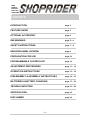
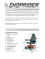
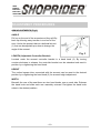
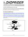
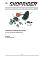
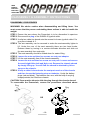
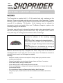
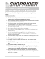
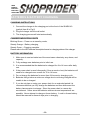
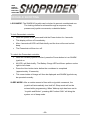
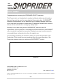
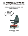
GMP ISO9001 ISO14001 ISO13485 CERTIFIED MEDICAL POWER WHEELCHAIR Owner’s Manual ATTENTION Please read your owner’s manual before driving your power wheelchair. STREAMER Sport 888WA ~0~ GMP ISO9001 ISO14001 ISO13485 CERTIFIED CONTENTS INTRODUCTION page 3 FEATURE GUIDE page 3 OPTIONAL ACCESSORY page 4 EMI WARNING page 5 – 6 SAFETY INSTRUCTIONS page 7 – 8 INDICATION LABEL LOCATION page 9 PREPARATION FOR USE page 10 PROGRAMMABLE CONTROLLER page 10 ADJUSTMENT PROCEDURES page 11 – 12 OPERATION INSTRUCTIONS page 13 – 14 DISASSEMBLY & ASSEMBLY INSTRUCTIONS page 15 – 16 BATTERIES & BATTERY CHARGING page 17 – 20 TROUBLE SHOOTING page 21 – 22 SPECIFICATION page 23 DISCLAIMER page 24 ~2~ GMP ISO9001 ISO14001 ISO13485 CERTIFIED INTRODUCTION Congratulations on receiving the STREAMER SPORT Powerchair. This Powerchair is the ultimate combination of style and comfort. The short wheelbase allows easy maneuverability within the smallest spaces both indoors and outdoors. The rear drive wheels and electromagnetic brakes provide a safe and comfortable ride. This manual contains important information regarding the safe use of the Powerchair. Please read it carefully before using the Powerchair and make sure you understand all the instructions. Warning! Please make sure that you are physically fit to operate this unit. Consult your dealer/doctor for advice. FEATURE GUIDE STREAMER SPORT (888WA) (1) (1) Headrest (adjustable with selected (2) height) (2) Backrest (3) Joystick Controller (4) Charging Port (5) Rear Drive Wheel(10”) (6) Front Castor (6”) (7) Armrest (adjustable with selected (8) (3) (7) (4) width, angle and height) (8) Captain Seat Assembly (9) Seat Supporting Post (9) (10) (10) Chassis Shroud (11) Footrest (12) Option (refer to page 4) (6) (11) Fig. 1 ~3~ (5) GMP ISO9001 ISO14001 ISO13485 CERTIFIED OPTIONAL ACCESSORY Item Accessory Part Example Adjustable Height Footrest Adaptor Elevating Leg Rest (6-hole adjustable as standard. 10hole adjustable with 60mm extension is optional.) Swing-Away Joystick Mount Bracket Remark: For other available accessories if required, please consult your authorized provider. ~4~ GMP ISO9001 ISO14001 ISO13485 CERTIFIED EMI WARNING ELECTROMAGNETIC INTERFERENCE (EMI) FROM RADIO WAVE SOURCES Medical Power Wheelchairs (Hereinafter referred to as “Powerchair”) may be susceptible to electromagnetic interference (EMI), which is a kind of interfering electromagnetic energy (EM) emitted from sources such as radio stations, TV stations, amateur radio (HAM) transmitters, two-way radio, and cellular phones. The interference (from radio wave sources) can cause the Powerchair to release its brakes, move by itself, or move in unintended directions. This can also permanently damage the Powerchair’s control system. The sources of radiated EMI can be broadly classified into three types: 1. Hand-held portable transceivers (transmitters-receivers) with the antenna mounted directly on the transmitting unit. Examples include: citizens band (CB) radios, “walkie talkie”, security, fire and police transceivers, cellular telephones, and other personal communication devices. NOTE! Some cellular telephones and similar devices transmit signals while they are ON, even when not being used. 2. Medium-Range mobile transceivers, such as those used in police cars, fire trucks, ambulances, and taxis. These usually have the antenna mounted on the outside of the vehicle. 3. Long-range transmitters and transceivers, such as commercial broadcast transmitters (radio and TV broadcast antenna towers) and amateur (HAM) radios. NOTE! Other types of hand-held devices, such as cordless phones, laptop computers, AM/FM radios, TV sets, CD players, and cassette players, and small appliances, such as electric shavers and hair dryers, so far as we know, are not likely to cause problems to the Powerchair. ~5~ GMP ISO9001 ISO14001 ISO13485 CERTIFIED EMI WARNING POWERCHAIR ELECTROMAGNETIC INTERFERENCE (EMI) Because EM energy rapidly becomes more intense as one moves closer to the transmitting antenna (source), the EM fields from hand-held radio sources (transceivers) are of special concern. It is possible to unintentionally bring high levels of EM energy very close to the Powerchair’s control system while using these devices. This can affect Powerchair movement and braking. Therefore, the warnings listed below are recommended to prevent possible interference with the control system of the Powerchair. WARNINGS 1. Do not operate hand-held transceivers (transmitters-receivers), such as citizens band (CB) radios, or turn ON personal communication devices, such as cellular phones, while the Powerchair is turned ON. 2. Be aware of nearby transmitters, such as radio or TV stations, and try to avoid close contact. 3. If unintended movement or brake release occurs, turn the Powerchair OFF as soon as it is safe. 4. Be aware that adding accessories or components, or modifying the Powerchair, may make it more susceptible to EMI. NOTE! There is no easy way to evaluate the overall immunity of the Powerchair. 5. Report all incidents of unintended movement or braking to the P o w e r c h a i r provider, and note whether there are sources of EMI nearby. ~6~ GMP ISO9001 ISO14001 ISO13485 CERTIFIED SAFETY INSTRUCTIONS Please use your Powerchair often and let it expand your horizons. The more mobility your Powerchair brings, the happier you will be! But, with all things, observing a few rules will ensure safe maneuvering. So please… (1) Do not drive the Powerchair without reading this instruction manual. (2) Do not use the joystick in an erratic manner when going up or down an incline. (3) Do not carry passengers or exceed the maximum user weight (Table 2). (4) Do not turn off the joystick controller by switching the On / Off Button when moving at speed. This will bring the electromagnetic brakes on imme diate ly a nd co uld cau se dam age t o t he joyst ick con tro lle r. (5) Do not drive over uneven or soft terrain. (6) Do not mount or dismount the Powerchair unless the electromagnetic brakes are engaged and the joystick controller is off. (7) Do not operate the Powerchair if the unit is in freewheel mode. (8) Do not use on the road, except when crossing between sidewalks. (9) Do not sit on the Powerchair when in a vehicle, but transfer to a vehicle seat. (10) Do not exceed any grade over 8 degrees (14%). (11) Always stop fully before changing forward or reverse direction. (12) Always engage a slow speed when going down gradients (move the joystick slowly towards center position to reduce the speed). (13) Always approach and climb over curbs at slow speed. (14) Always use the safety belt. (15) Always keep feet on the footrest while driving. (16) Always make sure the batteries are fully charged before setting out on a journey. (17) Always make sure the Allen bolt and the red tightening levers are tightened before driving the Powerchair. (18) Always charge the Powerchair in a well ventilated area. ~7~ GMP ISO9001 ISO14001 ISO13485 CERTIFIED SAFETY INSTRUCTIONS (19) Whenever a center bolt of the wheel assembly has been loosened, please replace with a specified new bolt from authorized providers and secure with a torque of 240 ± 5 kg-cm together with Loc-tite 271 adhesive (or equivalent). (20) When proceeding up any incline, please move the seat to the most forward position or if you have the deluxe seat, make sure that it is in the 90 degree (upright) position. (21) Do not adjust the programmer or modify the controller and cables without prior written approval from the manufacturer. Otherwise injury and/or damage to the scooter or surrounding property may occur. (22) Do not modify any parts on the unit without manufacturer’s written approval, or your warranty will be voided and you will be responsible for the modification. (23) Charge the batteries before using and charge batteries daily after use. (24) Battery cables must be securely fastened onto battery terminals by the authorized dealer before using the unit. Batteries must be tied down correctly and securely. (25) Use caution and reduce speed when turning. (26) Avoid using the powerchair in wet conditions. (27) Always make sure the seat post tightening levers have been tightened before driving the powerchair. (28) Do not use the powerchair as a seat in any vehicle. Remember! Give consideration to pedestrians whenever using the Powerchair. You are a motorized pedestrian and must observe all rules and regulations of other pedestrians wherever possible. ~8~ GMP ISO9001 ISO14001 ISO13485 CERTIFIED INDICATION LABEL LOCATION To ensure your safety and protect the Powerchair from damage, please read the safety instructions in this manual and familiarize yourself with the labels listed below. Labels on Chassis Shroud of STREAMER SPORT (888WA) Battery Wiring Diagram Drive Mode Drive Mode (Engaged) (Engaged) (Disengaged) (Disengaged) Free-wheel Mode Free-wheel Mode Caution: Before unit is driven, make sure the Brake Levers are in the Engaged position (at the Drive Mode) Fig. 2 ~9~ GMP ISO9001 ISO14001 ISO13485 CERTIFIED PREPARATION FOR USE The Powerchair has many features designed to give the user maximum comfort. Adjustments can be made to the following parts of the Powerchair: (1) Footrest angle can be adjusted from 8°~22°. (2) Armrests can be set at different angles. (3) Arms can be adjusted in height. (4) Arms can be adjusted in width. (5) Joystick controller can be fitted for either right or left hand use (no tools required). (6) Seat supporting posts with retaining pins can be adjusted in height. (7) Backrest angle can be slightly adjusted from 90°~102°. Adjustments should be carried out by a provider/attendant while the user is seated in the Powerchair with the Powerchair turned off (the seat height adjustment is made when the user is not on the seat). NOTE! Before using the Powerchair for the first time, be sure the batteries have been connected. Charge the Powerchair for at least 6-8 hours prior to first time use. PROGRAMMABLE CONTROLLER STREAMER SPORT (888WA) Powerchair has a programmable controller. For more information regarding the programming parameters for the programmable Powerchair controller please contact your provider. ~10~ GMP ISO9001 ISO14001 ISO13485 CERTIFIED ADJUSTMENT PROCEDURES ARM ADJUSTMENTS (Fig.3) ANGLE Pull up on the end of the armrests and they will flip back up allowing easy transfer in and out of the seat. Under the armrest, there is a bolt and lock nut (1) that can be adjusted up or down to change the angle of the armrest. (3) (1) (2) Fig. 3 LENGTH (Adjustable Controller Bracket) Located under the armrest controller bracket is a hand knob (2). By turning counter-clockwise to release, the controller bracket can be extended and reset in position by re-tightening the hand knob. HEIGHT The vertical square tube connected with the armrest can be reset to the desired position by re-tightening the hand knob (3) for armrest height adjustment. WIDTH Beneath the rear of the seat there are two hand knobs, one on each side. Release the hand knob and slide each arm assembly outward. Re-tighten the hand knob when in the desired position. ~11~ GMP ISO9001 ISO14001 ISO13485 CERTIFIED ADJUSTMENT PROCEDURES JOYSTICK CONVERSION (right to left or left to right) Loosen the hand knob [Fig.3 (3)] and remove the entire armrest assembly with the joystick attached. Place the armrest assembly on the desired side. Reset in position by re-tightening the hand knobs to complete joystick conversion. SEAT HEIGHT ADJUSTMENTS (Fig.4) The seat supporting post under the seat has three height adjustment holes. By tightening the Allen bolt and Nyloc nut in any one of the holes, three heights can be achieved and the seat supporting post can be secured to the power base. The seat tighten with the seat adaptor is secured to supporting post by two hex screws & nuts. Always make sure the Allen bolt with Nyloc nut and the hex screws with hex nuts are securely tightened before driving the Powerchair. The installing or setting-up method is described as Fig.4. Hex Nut Hex Nut Hex Screw Seat Supporting Post Nyloc Nut Hex Nut Allen Bolt Fig. 4 ~12~ GMP ISO9001 ISO14001 ISO13485 CERTIFIED OPERATION INSTRUCTIONS JOYSTICK CONTROLLER (SHARK 40) OVERVIEW 10 On / Off Button (1) This button turns the joystick controller (hereinafter referred to as SHARK 40 joystick) on and off. Do not use this button to stop the Powerchair, except in an emergency. Speed Decrease Button (2) This button decreases the maximum speed. Speed Increase Button (3) This button increases the maximum speed. Fig. 5 Horn Button (4) This button operates the Powerchair’s horn. Battery Gauge (5) This is a 8-segment display, which indicates if the SHARK 40 joystick is switched on and gives the state of charge of the battery. Maximum Speed Indicator (6) This is a 5-segment display, which indicates the maximum speed setting selected. Attendant Control LED (7) When the Attendant Remote is activated, the ACU LED will light up and remain lit until the attendant switches back to user mode. Service Indicator LED (8) The amber Service Indicator LED is dedicated to displaying joystick Flash Codes. For a list of Flash Codes and what faults they indicate. Refer to Table 1 for more details. Joystick (9) This controls the speed and direction of the Powerchair. Push the joystick in the direction you want to go. The further you push it, the faster the speed will be. Releasing the joystick will automatically engage brakes and stop the Powerchair. ~13~ GMP ISO9001 ISO14001 ISO13485 CERTIFIED OPERATION INSTRUCTIONS Charging Port (10) for Off-Board Charger Only plug a Shoprider certified charger into this port. This port should not be used as a power supply for any other electrical devices. Disregarding this will void the warranty of the Powerchair. GETTING READY TO DRIVE STEP 1 Press the On / Off Button, then the joystick will turn on after the Battery Gauge blinks for about a second. STEP 2 Press the Speed Increase / Decrease Button to set up a suitable level that you can maneuver the Powerchair easily. NOTE! The Powerchair will not move and the Battery Gauge will blink if you push the joystick before or right after you turn the joystick on. To restore the normal operating status, you have to release the joystick immediately back to its center position. If you do not release the joystick within five seconds, the Battery Gauge will flash rapidly. The Powerchair must be powered off and then turned back on again. STEP 3 Push the joystick to control the speed and direction of the Powerchair. NOTE! Choose an area with plenty of space to ride the Powerchair. Select the low level of the maximum speed setting until you are familiar with the controls. In a short time you will be in total control and can then increase the speed in steps. STEP 4 Release the joystick whenever you want to stop the Powerchair. ENGAGED / DISENGAGED MODE In the event of a fault or battery failure, the electromagnetic brakes can be disengaged allowing the Powerchair to be pushed. The levers should be switched to the freewheel position according to the indication labels of Fig.2 to set the Powerchair to the Engaged / Disengaged Mode. NOTE! Do not use or sit on the Powerchair when either of the brakes is disengaged, or the SHARK 40 joystick will not operate normally. ~14~ GMP ISO9001 ISO14001 ISO13485 CERTIFIED DISASSEMBLY & ASSEMBLY INSTRUCTIONS (2) (1) (3) (5) (4) Fig. 6 COMPONENTS FOR STREAMER SPORT (888WA) (1) Captain seat assembly with arm assembly. (2) Chassis shroud. (3) Chassis assembly. (4) Batteries. (5) Charger (Off-Board) ~15~ GMP ISO9001 ISO14001 ISO13485 CERTIFIED DISASSEMBLY & ASSEMBLY INSTRUCTIONS DISASSEMBLY PROCEDURES WARNING! We advise caution when disassembling and lifting items. You must ensure that the person undertaking these actions is able to handle the weight. STEP 1 Ensure the area where the Powerchair is to be dismantled is spacious. STEP 2 Disconnect the plug of the SHARK 40 joystick cable. STEP 3 Unclip two cable ties bound onto the armrest to loosen joystick cable if it’s one piece instead of 2. STEP 4 The arm assembly can be removed to make the seat assembly lighter to lift. Under the rear of the seat assembly there are two hand knobs. Release these by turning in a counter-clockwise direction and slide out the arm assembly from each side. STEP 5 The seat assembly should be folded down for easier lifting. STEP 6 Loosen the nuts and then hex screws on seat post adaptor. STEP 7 Lift the seat assembly free of the chassis assembly. STEP 8 Loosen the nut and then hex screw on seat post. Loosen and remove the seat height Allen bolt and Nyloc nut. Remove the chassis shroud by simply lifting up. You will find the shroud is attached by Velcro tapes on the chassis. STEP 9 Unclip a cable tie bound onto the seat post receiver of the chassis and then loosen the fastening strap on batteries. Unclip the battery plugs (red and black). The batteries can now, with the help of carrying straps provided, be lifted from chassis. CAUTION! Care must be taken to slide the plug through the chassis shroud. To reassemble the Powerchair, reverse the procedures described above. Plug Plug OR ~16~ GMP ISO9001 ISO14001 ISO13485 CERTIFIED BATTERIES & BATTERY CHARGING BATTERIES The Powerchair is supplied with 2 x 26 Ah sealed lead acid, maintenance free batteries. These are located under the seat in the center of the Powerchair. For easy handling, Velcro or plastic carrying straps may be provided to assist in installation or removal of the batteries. The duration of the batteries can be affected by temperature, terrain and weight of the user. The Battery Gauge is a guide on the remaining charge in the batteries. The active user will need to charge the batteries after using approximately more than 30% of battery capacity. As an inactive user, only using from once a week to every other day, the recharge point would be at 50% of discharge. The Battery Gauge is used to indicate power on and provides an estimate of the remaining battery capacity. Any green LEDs lit indicate will charged batteries. If only amber and red LEDs are lit, the batteries are moderately charged. Recharge before undertaking a long trip. If only red LEDs are lit, the batteries are running out of charge. Recharge as soon as possible Batteries should be kept fully charged at all times. They must not be left in a discharged state if not using the unit for some time. The batteries should be checked once a month and recharged as needed. Warning! ‧ Batteries contain acid and can explode. Always wear eye protection when working near batteries. ‧ Always keep battery terminals and clamps clean and free of corrosion. ‧ Never alter battery wiring or battery box. ‧ Never allow tools to make contact across terminals. ‧ Never use batteries or clamps with wing nut terminals, or clamps that exceed terminal post height. ‧ Do not smoke or use open flames when battery box lid is open. ‧ Only deep cycle, sealed case construction batteries should be used in this device. ~17~ GMP ISO9001 ISO14001 ISO13485 CERTIFIED BATTERIES & BATTERY CHARGING The following table indicates what the gauge will display for any given state. Display Description All LEDs OFF This means Power is OFF All LEDs ON steady Power is ON Left RED LED is Battery charge is flashing low Right to left “chase” Left to right “chase” alternating with steady display Alll LEDs flashing slowly 2 Flashing Amber LEDs Notes Less LEDs imply a reduced battery charge. The batteries should be charged as soon as possible SHARK joystick is To unlock SHARK being brought out of joystick, press the Horn Lock mode button twice within 10 seconds. SHARK joystick is The steady LEDs in programming, indicate the current inhibit and/or state of battery charge. charging mode SHARK joystick has detected an Out Of Neutral At Power Up (OONAPU) condition A communications fault exists between the power module and remote ~18~ Release the joystick back to neutral. Check the power module for a fault, the cable for damage, and that the battery is sufficiently charged. GMP ISO9001 ISO14001 ISO13485 CERTIFIED BATTERIES & BATTERY CHARGING BATTERY CHARGING (UNITS EQUIPPED WITH OFF-BOARD CHARGER) Familiarize yourself with the safety information below prior to using the battery charger. SAFETY INFORMATION 1. Read the battery charger instructions in this manual and in the manual supplied with the charger prior to charging the batteries. 2. Do not remove the grounding prong from the plug. Removal of the grounding prong could result in an electrical hazard. 3. Only plug the charger into a 3-pronged electrical outlet, or an approved 3-pronged adapter for use with a 2 pronged electrical outlet. 4. Make sure that the wall outlet being used is not controlled by a wall switch that can be easily turned off. 5. Do not use an extension cord to plug in the charger. 6. Do not leave the charger plugged into the charger port if the charger is not charging the unit. 7. Use only the off-board charger supplied with this unit. Never use an automotive type battery charger. Contact your supplier if a replacement off-board charger is needed. 8. Inspect the battery charger, wiring and connections for damage prior to each use. 9. Do not open the battery charger case. 10. The battery charger is supplied with cooling slots. Do not insert objects through the slots. 11. Make sure that the charger is not in contact with inflammable materials at any time. 12. The off-board charger is for indoor use only. 13. Explosive gases may be generated while charging the batteries. Keep the power chair and battery charger away from sources of ignition such as flames or sparks and provide adequate ventilation when charging the batteries. 14. Do not allow children to play near the power chair while the batteries are charging. It is also recommended that the batteries not be charged while the power chair is occupied. ~19~ GMP ISO9001 ISO14001 ISO13485 CERTIFIED BATTERIES & BATTERY CHARGING CHARGING INSTRUCTIONS 1. Connect the charger to the charging port at the front of the SHARK 40 joystick (item 8 in Fig.5) 2. Plug the charger into the wall outlet. 3. The charging process will start automatically. CHARGER INDICATION LIGHTS Blinking Green – Power on at stand-by mode, Steady Orange – Battery charging, Steady Green – Charging complete. Please refer to the LED indicator description based on charging status of the charger. BATTERY INFORMATION 1. Make sure to use two batteries of the exact same chemistry, amp hours, and capacity. 2. Fully recharge new batteries prior to initial use. 3. It is recommended that the batteries be charged for 8 to 14 hours after daily use. 4. If the power chair is used infrequently (Once a week or less) the batteries will need to be charged once a week for 12 to 14 hours. 5. Do not charge the batteries for more than 24 hours at a charging cycle. 6. Batteries that go below a minimum voltage due to not being charged will be unable to be re-charged. 7. If you do not plan on using your power chair for an extended period it is recommended that you fully charge the batteries and then disconnect the battery harness prior to storage. Store the power chair in a warm dry environment. Never store the batteries where extreme temperatures are possible. Never attempt to charge a frozen battery. A cold or frozen battery should be warmed for several days prior to charging. ~20~ GMP ISO9001 ISO14001 ISO13485 CERTIFIED TROUBLE SHOOTING The Self-Help Guide (Table 1) is intended to assist in the location of a fault that may occur in a certain part of the Powerchair. Flash codes indicate the nature of an abnormal condition directly from the SHARK joystick Information Gauge. Without the use of any servicing tools, the condition can be simply diagnosed. If after checking out the fault from the table below and the fault is still showing, do not use the Powerchair. Turn off the power and consult your provider immediately. Table 1 Flash Description Code User Fault Possible stall timeout or user error. Release the joystick to neutral and try again. 2 Battery Fault Check the batteries and cabling. Try charging the batteries. Batteries may require replacing. 3 Left Motor Fault Check the left motor connections and cabling. 4 Right Motor Fault Check the right motor connections and cabling. 5 Left Park Brake Fault Check the park brake connections and cabling. 6 Right Park Brake Fault Check the park brake connections and cabling. 7 SHARK Remote Fault Check the SHARK Communications Cable. Replace the Remote. 8 SHARK Power Module Fault Check the SHARK joystick connections and wiring. Replace the Power Module. 9 SHARK Communications Fault Check for possible low battery. Check the SHARK joystick connections and wiring. Check for worn motor brushes. Replace the Remote. 10 Unknown Fault Check all connections and wiring. Consult a service agent. 11 Incompatible Remote Wrong type of Remote connected. 1 ~21~ GMP ISO9001 ISO14001 ISO13485 CERTIFIED TROUBLE SHOOTING LOCK MODE: The SHARK 40 joystick can be locked to prevent unauthorized use. The locking method is achieved through a sequence of key presses and joystick movements, as detailed below. To lock Powerchair controller: While the power is ON, press and hold the Power button for 4 seconds. This display will turn off immediately. After 4 seconds all LED’s will flash briefly and the horn will sound a short beep. The Powerchair will then turn off. To unlock the Powerchair controller: While the SHARK joystick is locked, press the Power button to turn SHARK joystick on. All LED’s will flash briefly. The Battery Gauge LED’s will them perform a slow right-to-left chase. Press the Horn button twice before the countdown is completed (approximately 10 seconds). This current state-of-charge will then be displayed and SHARK joystick may be operated normally. SLEEP MODE: After a certain amount of time with no joystick movement, the joystick will automatically turn itself off. Sleep mode will not be entered while programming. When Wakeup style has been set to “Joystick and Button”, pressing ANY button ONLY will bring the system out of sleep mode. ~22~ GMP ISO9001 ISO14001 ISO13485 CERTIFIED SPECIFICATION Table 2 ITEM UNIT 888WA Overall Length1 Inches 38” Overall Width Inches 22” Overall Height Inches 40” Total Weight (w/ 26 Ah Batteries) Lbs 160 Battery Weight Lbs*pcs 17 lbs*2 Battery Capacity 12V_Ah x 2pcs 26Ah Safe Climbing Angle °(%) 8(14) Suggested User Weight (on level surface) Lbs Max. 300 Maximum Speed3 mph 5 Range (Per charge w/ standard 26 Ah battery) Miles 8 Charger Type On / Off Board Off Board 24V, 5A 4 ® ® All specifications are subject to change without prior notice. SHOPRIDER / PIHSIANG reserves the rights of any changes on the unit. 1. Includes the anti-tip wheel. 2. The actual driving range varies with the factors shown below. (1) the weight of occupant (2) ground surface (3) battery capacity and conditions (4) type of charger (5) ambient temperature (6) Driving methods (7) If the battery and mechanical moving parts fully broken in. ~23~ GMP ISO9001 ISO14001 ISO13485 CERTIFIED DISCLAIMER Congratulations on receiving the STREAMER SPORT Powerchair. This Powerchair is not intended to be used by individuals with physical limitations that could prevent the user from operating the Powerchair safely. SHOPRIDER® disclaims all responsibility for any personal injury or property damage, which may occur as a result of improper or unsafe use of its products. Mechanical or electrical defects will be dealt with on a contingency liability basis. Warranty is only valid when genuine SHOPRIDER® parts are used. All modifications on the Powerchair, unless approved and authorized by SHOPRIDER® will automatically invalidate the warranties. Standard warranty does not extend to consumable items and parties other than the original user. The preceding guidelines are intended to assist you in the safe operation of this Powerchair. If you should have any questions about the correct operation of the Powerchair, please contact your authorized SHOPRIDER® provider. . Provider Stamp Serial No.: SHOPRIDER MOBILITY PRODUCTS, INC 21184 S. FIGUEROA ST CARSON, CA 90745 800-743-0772 P/N: 300904-57-A6C © Copyright PIHSIANG MACHINERY MFG. CO., LTD. 2003. All rights Reserved. SHOPRIDER MACHINERY MFG. CO., LTD. ~24~ ® / PIHSIANG ® are registered trademarks of PIHSIANG