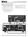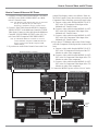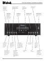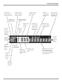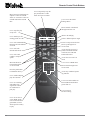
1
Owner’s Manual MVP851 DVD Audio / Video Player Manufactured under license from Dolby Laboratories. “Dolby”, “MLP Lossless” and the double-D symbol are trademarks of Dolby Laboratories. “DTS” and “DTS Digital Surround” are registered trademarks of Digital Theater Systems, Inc. This product incorporates copyright protection technology that is protected by method claims of certain U.S. Patents and other intellectual property rights owned by Macrovision Corporation and other rights owners. Use of this copyright protection technology must be authorized by Macrovision Corporation, and is intended for home and other limited viewing uses only unless otherwise authorized by Macrovision Corporation. Reverse engineering or disassembly is prohibited. McIntosh Laboratory, Inc. 2 Chambers Street Binghamton, New York 13903-2699 Phone: 607-723-3512 MVP851 FAX: 607-724-0549 The lightning flash with arrowhead, within an equilateral triangle, is intended to alert the user to the presence of uninsulated “dangerous voltage” within the product’s enclosure that may be of sufficient magnitude to constitute a risk of electric shock to persons. WARNING - TO REDUCE RISK OF FIRE OR ELECTRICAL SHOCK, DO NOT EXPOSE THIS EQUIPMENT TO RAIN OR MOISTURE. CAUTION - Invisible Laser Radiation when open. DO NOT stare into the beam or view directly with optical instruments. Use of controls or adjustment or performance of procedures other than those specified in the Owners Manual may result in Hazardous Radiation Exposure. LUOKAN 1 LASERLAITE KLASS 1 LASER APPARAT VAROITUS! Laitteen kayttaminen muulla kuin tassa kayttoohjeessa mainitulla tavalla saattaa altistaa kayttajan turvallisuusluokan 1 ylittavalle nakymattomalle lasersateiiylle. VARNING! Om apparaten anvands pa annat satt an i denna bruksanvisning specificerats, kan anvandaren utsattas for osynbg laserstraining, som overskrider gransen for laserklass 1. This product incorporates an embedded CLASS 2 Laser (CFR). 2 The exclamation point within an equilateral triangle is intended to alert the user to the presence of important operating and maintenance (servicing) instructions in the literature accompanying the appliance. NO USER-SERVICEABLE PARTS INSIDE. REFER SERVICING TO QUALIFIED PERSONNEL. To prevent the risk of electric shock, do not remove cover or back. No user serviceable parts inside. IMPORTANT SAFETY INSTRUCTIONS! PLEASE READ THEM BEFORE OPERATING THIS EQUIPMENT. General: 1. Read these instructions. 2. Keep these instructions. 3. Heed all warnings. 4. Follow all instructions. 5. Warning: To reduce risk of fire or electrical shock, do not expose this equipment to rain or moisture. This unit is capable of producing high sound pressure levels. Continued exposure to high sound pressure levels can cause permanent hearing impairment or loss. User caution is advised and ear protection is recommended when playing at high volumes. 6. Caution: to prevent electrical shock do not use this (polarized) plug with an extension cord, receptacle or other outlet unless the blades can be fully inserted to prevent blade exposure. Attention: pour pevenir les chocs elecriques pas utiliser cette fiche polarisee avec un prolongateur, une prise de courant ou un autre sortie de courant, sauf si les lames peuvent etre inserees afond ans en laisser aucune partie a decouvert. 7. Unplug this equipment during lightning storms or when unused for long periods of time. 8. Only use attachments/accessories specified by the manufacturer. Installation: 9. The equipment shall be installed near the AC Socket Outlet and the disconnect device shall be easily accessible. 10. Do not block any ventilation openings. Install in accordance with the manufacturer’s instructions. 11. Do not install near any heat sources such as radiators, heat registers, stoves, or other equipment (including amplifiers) that produce heat. 12. Do not use this equipment near water. 13. Do not expose this equipment to dripping or splashing and ensure that no objects filled with liquids, such as vases, are placed on the equipment. 14. Use only with the cart, stand, tripod, bracket, or table specified by the manufacturer, or sold with the equipment. When a cart is used, use caution when moving the cart/equipment combination to avoid injury from tip-over. Connection: 15. Connect this equipment only to the type of AC power source as marked on the unit. 16. Protect the power cord from being walked on or pinched particularly at plugs, convenience receptacles, and the point where they exit from the equipment. 17. Do not defeat the safety purpose of the polarized or grounding-type plug. A polarized plug has two blades with one wider than the other. A grounding type plug has two blades and a third grounding prong. The wide blade or the third prong are provided for your safety. If the provided plug does not fit into your outlet, consult an electrician for replacement of the obsolete outlet. 18. Do not overload wall outlets, extension cords or integral convenience receptacles as this can result in a risk of fire or electric shock. 19. To completely disconnect this equipment from the AC Mains, disconnect the power supply cord plug from the AC receptacle. Care of Equipment: 20. Clean only with a dry cloth. 21. Do not permit objects or liquids of any kind to be pushed, spilled and/or fall into the equipment through enclosure openings. 22. Unplug the power cord from the AC power outlet when left unused for a long period of time. Repair of Equipment: 23. Refer all servicing to qualified service personnel. Servicing is required when the equipment has been damaged in any way, such as power-supply cord or plug is damaged, liquid has been spilled or objects have fallen into the equipment, the equipment has been exposed to rain or moisture, does not operate normally, or has been dropped. 24. Do not attempt to service beyond that described in the operating instructions. All other service should be referred to qualified service personnel. 25. When replacement parts are required, be sure the service technician has used replacement parts specified by McIntosh or have the same characteristics as the original part. Unauthorized substitutions may result in fire, electric shock, or other hazards. 26. Upon completion of any service or repairs to this product, ask the service technician to perform safety checks to determine that the product is in proper operating condition. 3 Thank You Table of Contents Your decision to own this McIntosh MVP851 DVD Audio/ Video Player ranks you at the very top among discriminating music listeners. You now have “The Best.” The McIntosh dedication to “Quality,” is assurance that you will receive many years of musical enjoyment from this unit. Please take a short time to read the information in this manual. We want you to be as familiar as possible with all the features and functions of your new McIntosh. Safety Instructions ............................................................ 2 Thank You ......................................................................... 4 Please Take a Moment ...................................................... 4 Technical Assistance and Customer Service .................... 4 Table of Contents .............................................................. 4 Important Information ...................................................... 4 Introduction and Performance Features ............................ 5 Dimensions ....................................................................... 6 Installation ........................................................................ 7 Rear Panel Connections and Switch ................................. 8 How to Connect Control, Analog and Digital Audio ....... 9 How to Connect Video and AC Power ........................... 10 Front Panel Indicators, Push-Buttons and Switch .......... 12 Front Panel Display ........................................................ 13 Remote Control Push-Buttons ........................................ 14 How to Operate the Remote Control .............................. 15 How to Operate the Setup Mode .................................... 16 How to Operate ............................................................... 33 Specifications ................................................................. 46 Packing Instruction ......................................................... 47 Please Take A Moment The serial number, purchase date and McIntosh dealer name are important to you for possible insurance claim or future service. The spaces below have been provided for you to record that information: Serial Number: Purchase Date: Dealer Name: Technical Assistance If at any time you have questions about your McIntosh product, contact your McIntosh Dealer who is familiar with your McIntosh equipment and any other brands that may be part of your system. If you or your Dealer wish additional help concerning a suspected problem, you can receive technical assistance for all McIntosh products at: McIntosh Laboratory, Inc. 2 Chambers Street Binghamton, New York 13903 Phone: 607-723-1545 Fax: 607-723-3636 Customer Service If it is determined that your McIntosh product is in need of repair, you can return it to your Dealer. You can also return it to the McIntosh Laboratory Service Department. For assistance on factory repair return procedure, contact the McIntosh Service Department at: McIntosh Laboratory, Inc. 2 Chambers Street Binghamton, New York 13903 Phone: 607-723-3515 Fax: 607-723-1917 Copyright 2002 by McIntosh Laboratory, Inc. 4 Important Information 1. The following Connecting Cable is available from the McIntosh Parts Department: Data and Power Control Cable Part No. 170-202 Six foot, shielded 2 conductor, with 1/8 inch stereo mini phone plugs on each end. 2. For additional connection information, refer to the owner’s manual(s) for any component(s) connected to the MVP851 DVD Audio/Video Player. 3. The MVP851 will automatically power down to the Standby Mode 30 minutes after disc playback has stopped. Power to the MVP851 may be restored by pressing the Play Pushbutton on the Front Panel or Remote Control. 4. The MVP851 has built-in both 192kHz 24-Bit and 96kHz 24Bit DACs (Digital to Analog Converter) to allow playing of DVDs recorded with a higher bit and sample rate, by using the Analog Audio Outputs. 5. Several of the DVD performance features available on the MVP851 are active only if the DVD includes the supporting encoded information. 6. The translucent Remote Control Push-buttons, except for the Setup Push-button, will illuminate for approximately 3 seconds when activated. 7. DVD-Video Discs are designed to only play in certain region(s) of the world. A region may be a single country or a group of countries. Usually on the back cover of the DVDVideo Disc Container is a Globe Symbol with “Number(s)” or the word “All” inside it. The MVP851 is designed to play discs for Regions “1”, “1-3-4” and “All”. 8. The MVP851 Compact Disc Player is designed to play all Important Information and Connector Information Important Information, con’t standard CD Audio Discs that conform to the Official Compact Disc Standards which is indicated by the Symbol. It will also play most CD-R and CD-RW discs, however some recorded discs may not be able to play due to the condition of the recording. 9. CD Audio Discs recorded in the MP3 Format will playback on the MVP851 except discs that contain multi-session recordings. The MP3 Digital Signal is decoded to analog audio by the internal circuitry and is available at the Audio Outputs. A PCM version of the decoded MP3 Signal is available at the Digital Audio Outputs. 10. The MVP851 will Play Video CD Discs, DVD-RAM Discs (4.7GB Type only, without the cartridge) and some DVD-R discs, however some recorded discs may not be able to play due to the condition of the recording. 11. Compact Discs that are not round (e.g. Novelty discs with octagonal or heart shapes) will not play properly in the MVP851 and should not be tried, as possible damage may occur. 12. In order to view the Progressive Scan Video Output of the MVP851, the TV/Monitor connected to it must be capable of displaying a Progressive Picture and setup to display the Progressive Signal. 13. CAUTION: DO NOT ACTIVATE the MVP851 DVD Player’s Progressive Video Display Mode unless you are certain that the TV/Monitor connected to the MVP851 is capable of displaying a Progressive Scan Signal. Failure to do so could result in possible Damage to the TV/Monitor. 14. The Digital Audio Re-Master Enhancement Circuitry in the MVP851 affects both the Analog and Digital Audio Outputs when playing CDs. Not all Digital to Analog Processors can process the 88.2kHz sampling rate. 15. Some Multichannel DVD-Audio Discs might contain Low Frequency Audio Signals (below 80Hz) in the Center and/or Surround Channels. If the loudspeakers in your sound system that reproduce the Center and/or Surround Channels are not capable of reproducing those Low Frequencies, distortion and/or possible damage to the loudspeakers may occur. Consult with your dealer or refer to the Owner’s Manual for your loudspeakers for additional information. 16. The DVD-Audio Disc Audio Signal is converted internally from Digital to Analog. The Six Channel Analog Signals are available at the UNBALANCED AUDIO OUTPUTS 5.1CH. 17. Certain Dolby Digital and DTS Encoded Discs display their own unique Audio Mode Selection menu, every time the disc is loaded into the player. If you do not make a choice from this menu, the disc will revert to its default Audio Mode when play is started. 18. The MVP851 basic transport functions may also be controlled by using the Remote Control that comes with a McIntosh Control Center or Preamplifier. McIntosh Keypads can also be used to remotely control the basic transport functions of the MVP851. Remote Controls of certain McIntosh Control Centers or Preamplifiers also have additional Push-buttons including Direction Keys, Select, Important Information, con’t Title, Display and Menu that perform the same functions as the supplied MVP851 Remote Control. The labeling of Pushbuttons on some McIntosh Remote Controls and Keypads are different from the supplied MVP851 Remote Control. Refer to the listing below: MVP851 Remote Control McIntosh Remote Control/ Push-button Keypad Push-button Pause E +10 Review Connector Information XLR Connectors Below is the Pin configuration for the XLR Balanced Output Connectors on the MVP851. Refer to the diagram for connection: PIN 1: Shield/Ground PIN 2: + Output PIN 3: - Output Pin 1 Pin 2 Pin 3 Power Control Connector The MVP851 Power Control Input/Output Jacks provide Power On/Off Signals when connected to other McIntosh Components. A 1/8 inch Positive stereo mini phone plug is used for connecN/C tion to the Power Control Input/Output on Ground the MVP851. Data and IR Input Port Connectors The MVP851 Data Port Output provides Remote Control Signals. A 1/8 inch stereo mini phone plug is used for connection to the Data Port Inputs on McIn- Data tosh Source Units. The IR Ports also use a Signal N/C 1/8 inch stereo mini phone plug and allow Ground the connection of other brand IR Receivers to the MVP851. 5 Introduction and Performance Features Introduction The McIntosh MVP851 DVD Audio / Video Player offers the latest in audio/video technology to provide state of the art reproduction of digital video and audio program sources. A full complement of performance features allows the enjoyment of all the special audio and video formats available on a DVDs. Audio CDs are also reproduced with flawless realism. The advanced mechanical design of the transport ensures many years of smooth trouble free operation. Performance Features • Twin Laser Pickup The MVP851 incorporates two laser elements, with different wavelengths, that are focused through one lens assembly. This unique design allows reading many different types of Audio and Video Disc Formats. • Advanced Transport The MVP851 has a new Disc Stabilizer with a honeycomb structure made from glass reinforced Polyphenylene Ether and helps the playback of warped discs. It utilizes a Transport with the advanced digital servo for faster, quieter and accurate operation. • Progressive Scan Video Output The Component Video Output, with switchable Progressive Scan Processing, offers the highest possible picture quality available. • Component, S-Video and Composite Video Output The MVP851 has Component, S-Video and Composite Video Outputs for a variety of applications. • Advanced Video Circuitry An advanced technology 12-Bit DAC (Digital Analog Converter), with over 500 lines of horizontal resolution capability, performs video signal processing for enhanced DVD picture quality. • Digital Video Noise Reduction Circuitry The MVP851 incorporates a special 3D Dynamic Noise Reduction Circuit which effectively and selectively removes only the noise components from the signal for a clear image reproduction. • DVD-Audio Playback The MVP851 also plays DVD-Audio Discs that have higher resolution sound quality, plus the capability of multichannel sound reproduction. 6 • 24 BIT Burr Brown Audio DAC The MVP851 built-in Burr Brown Digital to Analog Converters are capable of sampling rates up to 192KHz with 24 Bits of resolution. There is one two channel 192kHz/24-bit DAC for the best sound quality in stereo reproduction from a DVD-Audio Disc and three two channel 96kHz/24-bit DACs for DVDs with six channel audio. • Balanced Outputs The MVP851 has Balanced Outputs for the Left and Right Channels when playing an Audio CD. When a Multichannel DVD disc is playing, the Balanced Left and Right Outputs contains a mix down of the Multichannel Sound. • Digital Re-Master Processing The optional Digital Re-Mastering Enhancement Circuitry in the MVP851 can improve the sound quality from Audio CDs by extending the frequency response beyond 20kHz. • Built-in Dolby Digital and DTS Digital Decoders The MVP851 provides built-in decoding of Dolby Digital or the DTS Digital Sound Tracks along with Level Calibration and Time Delay Adjustments. • Digital Audio Outputs There are Coaxial and Optical Digital Outputs for external decoding of Dolby Digital, DTS Digital Signals, PCM or MP3 Signals from Audio CDs. • Still Picture Display The Still Picture Display Mode allows selection of three different Still Picture Image qualities. The “I” Image offers the best picture quality, the “P” and “B” Images are generated from the differences between successive “I” Images. • Chapter Review The Chapter Review feature can automatically show the first three seconds of each chapter that was previously viewed and then start playing the movie where it left off. • Hi-Speed Smooth Motion Scan This feature provides quality scan in five speeds, ranging from slow motion to high speed of 100 times, in both forward and reverse. • On Screen Menu Icons This feature allows control of a variety of settings via Remote Control. Dimensions MVP851 Dimensions The following dimensions can assist in determining the best location for your MVP851. There is additional information on the next page pertaining to installing the MVP851 into cabinets. 17-1/2" 44.45cm 5 -3/8" 13.69cm Front View of the MVP851 6" 15.24cm 17" 43.18cm 4 -5/8" 11.75cm Rear View of the MVP851 13 -1/4" 33.65cm 13-1/8" 33.38cm 12" 30.48cm 3/16" 0.48cm Side View of the MVP851 4-13/16" 12.22cm 13/16" 2.06cm 9-1/16" 23.01cm 7/8" 2.23cm 7 Installation Installation The MVP851 can be placed upright on a table or shelf, standing on its four feet. The four feet may be removed from the bottom of the MVP851 when it is custom installed as outlined below. The four feet together with the mounting screws should be retained for possible future use if the MVP851 is removed from the custom installation and used free standing. It also can be custom installed in a piece of furniture or cabinet of your choice The required panel cutout, ventilation cutout and unit dimensions are shown. Always provide adequate ventilation for your MVP851. Cool operation ensures the longest possible operating life for any electronic instrument. Do not install the MVP851 Front Panel MVP851 diCustom Cabinet Cutout rectly above a heat generating component such as a high powered amplifier. If all the components are installed in a Cabinet single cabinet, Front Panel a quiet running ventilation fan can be a definite asset MVP851 Side View in maintaining in Custom Cabinet all the system components at the coolest possible operSupport Shelf ating temperature. A custom cabinet installation should provide the 5" MVP851 Bottom View 12.7cm following in Custom Cabinet minimum spacing dimensions for 8 cool operation. Allow at least 2 inches (5.08 cm) above the top, 2 inches (5.08cm) below the bottom and 1 inch (2.54 cm) on each side of the DVD Player, so that airflow is not obstructed. Allow 15 inches (38.1 cm) depth behind the front panel. Allow 1 inch (2.54 cm) in front of the mounting panel for clearance. When the DVD/CD tray is opened, the panel clearance required in front of mounting panel is 6-3/4 inches (17.2cm). Be sure to cut out a ventilation hole in the mounting shelf according to the dimensions in the drawing. 17-1/16" 43.34cm 4 -7/8" 12.38cm Cutout Opening for Custom Mounting Cutout Opening for Ventilation Chassis Spacers 3-1/2" 8.89cm 6" 15.24cm 8-1/2" 21.6cm Cutout Opening for Ventilation 13-1/4" 33.65cm MVP851 Rear Panel Connections UNBALANCED AUDIO OUTPUT supplies Two Channels of Analog Audio and connects to the Analog Input of an A/V Control Center DIGITAL COAXIAL OUTPUT sends signals to a Control Center with a D/A Converter DIGITAL OPTICAL OUTPUT sends signals to a Control Center with a D/A Converter UNBALANCED AUDIO OUTPUT supplies Six Channels of Analog Audio and connects to the External Input of an A/V Control Center PR OUTPUT supplies the Red minus Luminance Video Signal and connects to the PR Component Input of the TV/Monitor or other video component VIDEO OUTPUT supplies video signals to connect to a Composite Input of an A/V Control Center or other video component BALANCED AUDIO OUTPUTs contain analog stereo signals to connect to Balanced Inputs of other components DATA IN receives operating data from a McIntosh Control Center Y OUTPUT supplies the Luminance Video Signal and connects to the Y Component Input of the TV/Monitor or other video component PB OUTPUT supplies the Blue minus Luminance Video Signal and connects to the PB Component Input of the TV/Monitor or other video component S-VIDEO OUTPUT supplies video signals to connect to an S Input of an A/V Control Center or other video component Connect the MVP851 power cord to a live AC outlet. Refer to information on the back panel of your MVP851 to determine the correct voltage for your unit POWER CONTROL IN receives turn-on signals from a McIntosh component and POWER CONTROL OUT sends turn-on signals on to another McIntosh Component IR INput for connecting an IR Receiver 9 How to Connect Control, Analog and Digital Audio How to Connect Control, Analog and Digital Audio 1. Connect a Power Control Cable from the MVP851 POWER CONTROL IN to the POWER CONTROL ACC Output jack of a McIntosh A/V Control Center. 2. Connect a Data Cable from the MVP851 DATA IN jack to the DVD DATA (11) jack on the McIntosh A/V Control Center. 3. Connect a Coaxial Cable from the MVP851 COAXIAL DIGITAL OUT to the DVD Coaxial DIGITAL INPUT (F) of a McIntosh A/V Control Center. 4. Connect Audio Cables from the MVP851 L and R AUDIO OUTPUTS 2CH to the DVD AUDIO INPUTS on a McIntosh A/V Control Center. 5. Connect Audio Cables from the MVP851 AUDIO OUTPUTS 5.1CH (all six channels) to the External AUDIO INPUTS on a McIntosh A/V Control Center. Note: An optional connecting method is to use an optical cable from the MVP851 OPTICAL DIGITAL OUTPUT to the Optical Digital Input of a McIntosh A/V Control Center. McIntosh A/V Control Center 10 How to Connect Video and AC Power How to Connect Video and AC Power 1. Connect a S-Video Cable from the MVP851 S-VIDEO OUTPUT to the DVD S-VIDEO INPUT on a McIntosh A/V Control Center. Note: The MVP851 Video Outputs may also be connected directly to a Monitor/TV if no Video Input Switching is available in the A/V Control Center. 2. Connect a Video Cable from the MVP851 Composite VIDEO OUTPUT to the Multizone Controller V-DVD Video Input. Connect a video cable from the Multizone Controller V-DVD VIDEO OUTPUT to the A/V Control Center DVD Composite DVD VIDEO INPUT. Note: If a McIntosh Multizone Controller is not used, connect MVP851 Composite VIDEO OUTPUT to the A/V Control Center DVD Composite DVD VIDEO INPUT. 3. If you have an Audio/Video Control Center with ComMcIntosh Multizone Controller ponent Video Inputs, connect it as follows. If the Audio/Video Control Center does not have provisions for Component Video Switching, proceed to step 4 below. A. Connect a video cable from the MVP851 Y OUTPUT to the Y2 Component Video Input of the McIntosh A/V Control Center. B. Connect a video cable from the MVP851 PB OUTPUT to the PB2 Component Video Input of the McIntosh A/V Control Center. C. Connect a video cable from the MVP851 PR OUTPUT to the PR2 Component Video Input of the McIntosh A/V Control Center. 4. If you have a TV/Monitor and/or other Video Component with Component Video Inputs then connect as follows: A. Connect a video cable from the MVP851 Y OUTPUT to the Y Component Video Input of the TV/ Monitor or other video component. B. Connect a video cable from the MVP851 PB OUTPUT to the PB Component Video Input of the TV/ Monitor or other video component. C. Connect a video cable from the MVP851 PR OUTPUT to the PR Component Video Input of the TV/ Monitor or other video component. 5. Connect the MVP851 power cord to a live AC outlet. McIntosh A/V Control Center Connect to AC Outlet 11 Front Panel Indicators, Push-Buttons and Switch Indicates the Digital Re-Master Audio Processing Circuit is On Indicates the Progressive Scan Video Processing Circuit is On Indicates the 3D Digital Dynamic Noise Reduction Video Processing Circuit is On Activates the Progressive Scan Video Processing Circuit Activates the 3D Digital Dynamic Noise Reduction Video Processing Circuit 12 Disc Tray opens to load and unload a disc Front Panel Alphanumeric and Symbol Display Activates the Digital ReMaster Audio Processing Circuit IR Sensor receives commands from a remote control Use to Pause during play Move rapidly forward through a disc during play or move forward one track/chapter at a time Move rapidly backward through a disc during play or moves back one track/chapter at a time Standby Power On Indicator Stops disc Play Starts disc Play POWER Switch turns all AC power completely ON or OFF Opens and Closes the disc tray for loading or unloading discs STANDBY/ON Push-button switches the MVP851 ON or OFF (Standby) Front Panel Display Indicates the Preselected Track Play Mode is active Indicates when a CD Disc (Audio or Video) is loaded Indicates the Random Play Mode is active Indicates Chapter Number of the Disc Indicates Repeat Mode is active Indicates the current MultiChannel Sound track can be down mixed to 2 Channels Indicates when a DVD-Audio Disc is loaded Indicates when the disc contains a Multi-Channel Sound Indicates Various Scrolling Text Mesages Indicates when a CDVideo Disc is loaded Indicates when a DVD-Video Disc is loaded Indicates when the Digital Audio Re-Master Processor is active Indicates when the A-B Repeat Mode is active Indicates Title Number on the Disc Indicates when a DVD Disc (Audio or Video) is loaded Indicates Packed PCM Digital Audio Format Indicates when in the Pause Mode Indicates the Group Number on DVD-Audio Discs Indicates Track Number of the Disc Indicates the current Track Time, Remaining Track Time, Total Disc Playing Time and various Programming Information Indicates when the Play Mode is active 13 Remote Control Push-Buttons Move forward or backward one chapter at a time on a DVDVideo; or one track at a time on a DVD-Audio Disc and CD Disc Use to stop disc play at any time Use to mark up to five starting points on a disc Use to temporarily stop disc play and advance a video frame at a time on a DVD Use to access the initial Settings Menu Move forward or backward through a DVD or CD Starts a disc Playing Select a different picture Angle Use to select DVD Subtitle language and turn subtitles on or off Cancel a setup menu selection Use to select the desired audio mode Access the title screen of a DVD; Text Based Information from some CDs and DVD-Audio Discs Use to select and confirm a setup option Move Backward or Forward through an on screen menu Press the push-button to illuminate the keys Move Up through an onscreen menu Access the on-screen icon menu Use to access a DVD menu Move Down through an onscreen menu Access any numbered operating function Use to enable a Repeat play disc function Use to set a starting and ending time segment on a disc for continuous repeat play Use to access the on screen DVD-Audio, CD or CD-Video Program Menu to select which specific track(s) to play 14 To access Track Numbers on CDs and DVD-Audio Discs greater than 10 Use to Clear an incorrect setting How to Operate the Remote Control How to Operate the Remote Control The Remote Control is capable of performing both basic Operating Functions and Setup Options for the MVP851 Disc Player. Note: Refer to the “How to Operate Setup Mode” and “How to Operate” Sections of this manual for more detailed information. Play With a disc loaded, press the PLAY push-button to start the disc playing. Stop Press the STOP push-button to stop disc play at any time. Press PLAY and the disc will start playing again from the disc time where STOP was pressed. Press STOP three times to return to the beginning of a disc. Numbered Push-buttons For DVD-Video - Press combinations of 0 through 9 to directly access DVD Chapters using the On-screen Icon. For example to access Chapter 23, press 2, 3 and then SELECT. Note: This function requires pressing the DISPLAY push-button first, to access the On-screen Icon. For DVD-Audio - Press 0 through 9 to access Tracks numbers less than 10. For track numbers and CDs greater than 10, press the +10 push-button first and then required number. For example to access Track 23, press +10 and then 23. Clear Press the CLEAR push-button to erase a selected track or incorrect setting. Pause Press the PAUSE push-button to temporarily stop play operation at any time on a DVD or CD. When a DVD is playing, each time the PAUSE push-button is pressed again, the player will jump to the next video frame. Back and Next Press the NEXT push-button to move forward or the BACK push-button to move backward one chapter at a time on a DVD or one track at a time on a CD. Return Press the RETURN push-button to cancel a setup menu selection. Setup Press the SETUP push-button to access the Initial Setup Menu. Subtitle Press the SUBTITLE push-button to access the Subtitle menu and the Subtitle icon will appear at the top of the screen. Marker While a disc is playing, use MARKER push-button to establish in memory up to five different starting points on a disc where you wish play to start other than at the beginning. Angle If the DVD being played supports the Angle Feature, press the ANGLE push-button to select the desired video picture angle. Four Direction Arrows Press an Arrow direction push-button to move backward, forward, up or down through an on-screen menu. Select Press the SELECT push-button to confirm and activate a setup option or options indicated by the on-screen icons. Title When a disc is loaded in the player, press the TITLE pushbutton to access the DVD Title menu. Display Press the DISPLAY push-button to access the on-screen options icons. Audio Press the AUDIO push-button to access the sound track format you wish to activate. REV and FF Press a REV (Reverse) or FF (Fast Forward) push-button to start moving rapidly through a chapter or track on a disc. Note: Audio level is automatically reduced during this operating mode. A-B Repeat Press the A-B REPEAT push-button once to establish the starting point of the repeat loop and press the A-B REPEAT push-button a second time for the ending point, and that segment of a disc to be repeated continuously. 15 How to Operate the Setup Mode Your McIntosh MVP851 has been factory configured for default operating settings that will allow you to immediately enjoy superb video and high fidelity audio from a DVD-Video. It also reproduces DVD-Audio and CDs with unparalleled sonic purity. If you wish to make changes to the factory default settings, a Setup feature is provided to customize the operating settings using On Screen Menus. Note: The MVP851 must be connected to a MONITOR/TV either through an A/V Control Center or directly, for setup and use. 1. Press the Front Panel POWER Switch to ON. The Red LED above the STANDBY/ON switch lights to indicate the MVP851 is in Standby mode. To Switch ON the MVP851, press the STANDBY/ON Push-button. Refer to figure 1. 2. Press the SETUP Pushbutton on the Remote Control and the Disc Setup Menu will appear on the Monitor/TV screen. Refer to figures 2 & 3. Note: There are five Main Menu Icon Figure 1 Tabs located at the Top of the On-Screen Setup Display. The Icon Tabs are named Disc, Video, Audio, Display and Others. 3. Access the desired Main Menu Icon Tab by pressing the Right or Left directional push-buttons on the supplied Remote Control. Then use the Up or Down directional push-buttons followed by the SELECT Push-button for the desired choice. Figure 2 Main Menu Icon Tabs Note: Some menu choices require more than one step to complete. 4. The desired Menu Icon will then appear on the MONITOR/TV screen for further action. Follow the instructions for each of the desired setup menus. 5. After all setup adjustments are complete, press the RETURN Push-button to exit the Setup Mode. Note: Depending upon what Setup Menu is on the screen, several presses of the RETURN Push-button may be required to exit the Setup Mode. Figure 3 16 SETUP and Default Settings Setup Mode Default Settings The following listings indicate the factory default settings. Refer to the listed page number for instructions on how to change a default setting. MAIN SETTINGS FOR: Disc: Name Selection Refer to Page Audio Preference ............ English ................................ 18 Subtitle ............................ Automatic............................ 18 Menu ............................... English ................................ 19 Ratings ............................ Level 8 (Unlocked) ............. 20 Video: Name Selection Refer to Page TV Aspect ....................... 4:3 Pan & Scan ................... 22 TV Type .......................... Standard(Direct View TV) .. 22 Still Mode ....................... Automatic............................ 23 Black Level Control ....... Lighter ................................. 23 Audio: Name Selection Refer to Page Speaker Setting ............... Multi-channel ...................... 24 MULTI-CHANNEL SETTINGS FOR: Speaker Size: Name Selection Refer to Page Front ............................. Large ................................ 25 Center ........................... Large ................................ 25 Left Surround ............... Large ................................ 25 Right Surround ............. Large ................................ 25 Subwoofer .................... Yes ................................... 25 Speaker Time Delay: Name Time Delay Refer to Page Front ............................. Reference ......................... 25 Center ........................... 0 ms .................................. 25 Surround ....................... 0 ms .................................. 25 Subwoofer .................... Reference ......................... 25 Speaker Level: Name Initial Level Refer to Page Front ............................. Reference ......................... 27 Center ........................... 0dB ................................... 27 Left Surround ............... 0dB ................................... 27 Right Surround ............. 0dB ................................... 27 Subwoofer .................... 0dB ................................... 27 Digital Audio Output ...... On ........................................ 28 PCM Down Conversion . Yes ....................................... 28 Dolby Digital .................. Bitstream ............................. 29 DTS Digital Surround ..... Bitstream ............................. 29 D. Range Compression ... Off ....................................... 30 Audio during Search ....... On........................................ 30 Display: Name Selection Refer to Page Menu Language .............. English ................................ 31 On-Screen Messages ...... On........................................ 31 Others: Name Selection Refer to Page Demo .............................. Off ....................................... 32 Video Preference Default Settings The following listings indicate the factory default settings. Refer to the listed page number for instructions on how to change a default setting. Note: The Video Menus are accessed On-Screen with the Remote Control. Display Settings: Name Selection Refer to Page Video Bit Rate ................ Off ....................................... 45 Front Panel ...................... Bright .................................. 45 Main Video Menu: Name Selection Refer to Page Digital Picture Mode ...... Normal ................................ 43 U1 Video Menu: Name Setting Refer to Page Contrast, Brightness, ...... 0 .......................................... 44 Sharpness, Color and Gamma U2 Video Menu: Name Setting Refer to Page 3D-NR, Block NR .......... 0 .......................................... 44 and Mosquito NR U3 Video Menu: Name Selection Refer to Page High sharpness, ............... 0 .......................................... 44 V sharpness, Edge and Tint U4 Video Menu: Name Selection Refer to Page Transfer Mode ................ Auto 1 ................................. 45 4:3 Aspect ....................... Auto .................................... 45 Shift Position .................. 0 .......................................... 45 Output ............................. Nor. (Normal) ...................... 45 17 How to Set Disc Language This is to select the Language of the Soundtrack, Subtitles, Menu Titles and DVD Menus. Note: If a disc is playing when the SETUP Push-button is depressed it will stop. When the SETUP Mode is exited the disc will resume playing. Audio Preference This selects the dialog language that will be heard when the DVD-Video Disc is played. Note: The Alternate Languages of French and Spanish may not be available on all DVD-Video Discs. 1. Press the SETUP Push-button on the Remote Control to access the On-Screen Setup Disc Menu. Refer to figures 4 and 8. 2. Select the Audio Icon by using the Up or Down directional Push-buttons followed by the SELECT Push-button on the supplied Remote Control. 3. The Audio Preference Menu will now appear on the screen with the default selection of English. Refer to figure 5. 4. To change that setting to another language use the Up or Down directional Push-buttons followed by the SELECT Push-button. Figure 4 Note: The Audio Preference choice of “Other” is for use outside of North America. 5. Return to the Disc Menu by pressing the RETURN Push-button once. 6. Next continue to the SUBTITLE Settings. If no other changes are to be made in Setup Mode at this time, exit by pressing the RETURN Push-button and the MVP851 will return to normal operation. Subtitle This selects the language that will be seen on the TV/Monitor when the DVD-Video Disc is played and the Subtitle Mode is active. Figure 5 Note: The Alternate Languages of French and Spanish may not be available on all DVD-Video Discs. 1. If the MVP851 is not already in the Setup Mode, press the SETUP Push-button on the Remote Control to access the On-Screen Setup Disc Menu. Refer to figures 4 and 8. 2. Select the Subtitle Icon by using the Up or Down directional Push-buttons followed by the SELECT Push-button on the supplied Remote Control. 3. The Subtitle Preference Menu will now appear on the screen with the default selection of Automatic. Refer to figure 6. Note: In the Automatic Mode the language of the Subtitles will be the same as the Audio Language Selected for Figure 6 18 SETUP, con’t that movie, unless that language is not available on that specific disc. 4. To change the setting to a specific language use the Up or Down directional Push-buttons followed by the SELECT Push-button. Note: The Subtitle Preference choice of “Other” is for use outside of North America. 5. Return to the Disc Menu by pressing the RETURN Push-button once. 6. Next continue to the MENUS Settings. If no other changes are to be made in Setup Mode at this time, exit by pressing the RETURN Push-button and the MVP851 will return to normal operation. Menus This selects the language of the menus that will be seen on the TV/Monitor. Figure 7 Note: The Alternate Languages of French and Spanish may not be available on all DVD-Video Discs. 1. If the MVP851 is not already in the Setup Mode, press the SETUP Push-button on the Remote Control to access the On-Screen Setup Disc Menu. Refer to figures 4 and 8. 2. Select the Menus Icon by using the Up or Down directional Push-buttons followed by the SELECT Push-button on the supplied Remote Control. 3. The Menu Preference Menu will now appear on the screen with the default selection of English. Refer to figure 7. 4. To change that setting to a specific language use the Up or Down directional Push-buttons followed by the SELECT Push-button. Note: The Menu Preference choice of “Other” is for use outside of North America. 5. Return to the Disc Menu by pressing the RETURN Push-button once. 6. Next continue to the RATINGS Settings. If no other changes are to be made in Setup Mode at this time, exit by pressing the RETURN Push-button and the MVP851 will return to normal operation. Figure 8 19 How to Set Ratings Some DVD Movie discs have encoded rating levels that allow the setting of the MVP851 to prevent children from viewing inappropriate movies in your absence. A password protected lock function, set by you, sets the rating limit for disc playback. In the example below the Rating Limit will be set to Level 3 with a password of 1234. Note: A Rating Level of 8 allows viewing of all DVD Movies and “0 Lock All” prevents any disc from being viewed. It is advisable to write down the password for future reference, as once a password has been entered it will stay in effect until removed or changed. 1. Press the SETUP Push-button on the Remote Control to access the On-Screen Setup Disc Menu. Refer to figure 4 on page 18 and figure 8 on page 19. Note: If a disc is playing when the SETUP Push-button is depressed it will stop. When the SETUP Mode is exited the disc will resume playing. Figure 9 2. Select the Ratings Icon by using the Up or Down directional Push-buttons followed by the SELECT Push-button on the supplied Remote Control. 3. The Ratings Menu will now appear On-Screen with the default selection of 8 No Limit. Refer to figure 9. 4. Using the Up or Down directional Push-buttons select a Rating Limit of 3 followed by the SELECT Push-button. Refer to figures 10 and 11. 5. Enter the Password of 1234, using the Numeric Pushbuttons on the Remote Control, into the On-Screen Password Icon followed by the SELECT Push-button. Refer to figure 12. Note: If an undesired number is entered, the CLEAR Pushbutton on the Remote Control can be used to remove it. Each press of the push-button will remove one digit at a time starting with the digit on the right side. 6. The Setup Disc Menu will reappear. If no other changes are to be made in Setup Mode at this time, exit by pressing the RETURN Push-button and the MVP851 will return to normal operation. Unlock the Player 1. Press the SETUP Push-button on the Remote Control to access the On-Screen Setup Disc Menu. Refer to figure 4 on page 18 and figure 8 on page 19. 2. Select the Ratings Icon by using the Up or Down directional Push-buttons followed by the SELECT Push-button. 3. The Ratings Password Enter Icon will now appear OnScreen. Refer to figure 13. 4. Using the Numeric Push-buttons on the Remote Control, enter the previously set password followed by the SELECT Push-button. Refer to figure 14. 20 Figure 10 Figure 11 SETUP, con’t Note: If an undesired number is entered, the CLEAR Pushbutton on the Remote Control can be used to remove it. Each press of the push-button will remove one digit at a time starting with the digit on the right side. 5. Select the Unlock Player Icon by using the Up or Down directional Push-buttons followed by the SELECT Push-button. Refer to figure 10. 6. Continue next to Change Password or exit the Setup Mode by pressing the RETURN Push-button and the MVP851 will return to normal operation. Change Password 1. Perform steps 1-4 of “Unlock the Player”. 2. Select the Change Password Icon by using the Up or Down directional Push-buttons followed by the SELECT Push-button. Refer to figure 14. 3. Enter the Password into the On-Screen Password Icon followed by the SELECT Push-button. 4.Continue next to Change Rating Level or exit the Setup Mode by pressing the RETURN Push-button and the MVP851 will return to normal operation. Change Ratings Level 1. Perform steps 1-4 of “Unlock the Player”. 2. Select the Change Level Icon by using the Up or Down directional Push-buttons followed by the SELECT Push-button. Refer to figure 14. 3. Using the Up or Down directional Push-buttons and select the desired Rating Limit followed by the SELECT Push-button. Refer to figure 9. 4.Continue next to Temporary Unlock or exit the Setup Mode by pressing the RETURN Push-button and the MVP851 will return to normal operation. Figure 12 Figure 13 Temporary Unlock 1. Perform steps 1-4 of “Unlock the Player”. 2. Select the Temporary Unlock Icon by using the Up or Down directional Push-buttons followed by the SELECT Push-button. The On-Screen Message will indicate that the current disc in the MVP851 will now play. Refer to figure 14. 3. Continue next to Video Display Modes or exit the Setup Mode by pressing the RETURN Push-button and the MVP851 will return to normal operation. Figure 14 21 How to Set Video Display Modes This is to select how the Video Signal is displayed on the TV/Monitor and when the Picture Still Mode is active. TV Aspect This feature allows configuring the MVP851 to match your Monitor/TV Aspect Ratio (width to height screen dimension) and/or personal preference. 1. Press the SETUP Push-button on the Remote Control to access the Setup Disc Menu. Refer to figure 4 on page 18 and figure 8 on page 19. 2. Use the Right or Left directional Push-buttons to select the Video Menu Icon Tab. 3. Select the TV Aspect Icon by using the Up or Down directional Push-buttons followed by the SELECT Push-button. Refer to figure 15. 4. Use the Up or Down directional Push-buttons and choose the TV Aspect Ratio for the desired display, followed by the SELECT Push-button. 4:3 Pan&Scan Mode (refer to figure 16) 4:3 Letterbox Mode (refer to figure 17) 16:9 Wide Screen Mode (refer to figure 18) 5. Continue next to TV Type or exit the Setup Mode by pressing the RETURN Push-button and the MVP851 will return to normal operation. TV Type The MVP851 is capable of optimizing the picture quality according to the type of Video Display that is used. This optimization occurs when a Monitor/TV capable of displaying a Progressive Scan Signal is connected to the MVP851 and the Progressive Scan Mode is active on both the player and TV/Monitor. 1. Press the SETUP Push-button on the Remote Control to access the Setup Disc Menu. Refer to figure 4 on page 18 and figure 8 on page 19. 2. Use the Right or Left directional Push-buttons to select the Video Menu Icon Tab. 3. Select the TV Type Icon by using the Up or Down directional Push-buttons followed by the SELECT Push-button. Refer to figure 19. 4. Use the Up or Down directional Push-buttons and choose the TV Display Type, followed by the SELECT Push-button. Standard (Direct View TV) CRT Projector LCD Projector (or DLP Projector) Projection TV 5. Continue next to Still Mode or exit the Setup Mode by pressing the RETURN Push-button and the MVP851 22 Figure 15 Figure 16 Figure 17 Figure 18 SETUP, con’t will return to normal operation. Still Mode The Still Mode setting of Automatic should be satisfactory when viewing a single video frame at a time. If you encounter video picture jittering or fuzzy small text with a certain disc, select Field or Frame to correct the problem. 1. Press the SETUP Push-button on the Remote Control to access the Setup Disc Menu. Refer to figure 4 on page 18 and figure 8 on page 19. 2. Use the Right or Left directional Push-buttons to select the Video Menu Icon Tab. 3. Select the Still Mode Icon by using the Up or Down directional Push-buttons followed by the SELECT Push-button. Refer to figure 20. 4. Use the Up or Down directional Push-buttons and choose the desired Still Mode, followed by the SELECT Push-button. Automatic (Selects either Field or Fame) Field (Use if picture jittering is present) Frame (Use to make small text clearer) 5. Continue next to Black Level Control or exit the Setup Mode by pressing the RETURN Push-button and the MVP851 will return to normal operation. Black Level Control This allows configuring the MVP851 to match the Video Connection Type used between it and the Monitor/TV. 1. Press the SETUP Push-button on the Remote Control to access the Setup Disc Menu. Refer to figure 4 on page 18 and figure 8 on page 19. 2. Use the Right or Left directional Push-buttons to select the Video Menu Icon Tab. 3. Select the Black Level Control Icon by using the Up or Down directional Push-buttons followed by the SELECT Push-button. Refer to figure 21. 4. Use the Up or Down directional Push-buttons and choose the desired Black Level Control, followed by the SELECT Push-button. Lighter (Video Output and S-Video Output) Darker (Component Video Output) 5. Continue next to Audio Parameters on the next page or exit the Setup Mode by pressing the RETURN Pushbutton and the MVP851 will return to normal operation. Figure 19 Figure 20 Figure 21 23 How to Set Audio Parameters The MVP851 allows the configuring of various audio parameters to match the number and size of Loudspeakers in the system along with the type of A/V Control Center and/ or Decoder being used. It also allows for changes to the audio during the playback of a disk. Speaker Setting This feature allows configuring the MVP851 to match the number of amplifier/loudspeaker channels available in your Audio System. 1. Press the SETUP Push-button on the Remote Control to access the Setup Disc Menu. Refer to figure 4 on page 18 and figure 8 on page 19. 2. Use the Right or Left directional Push-buttons to select the Audio Menu Icon Tab. 3. Select the Speaker Setting Icon by using the Up or Down directional Push-buttons followed by the SELECT Push-button. Refer to figure 22. 4. Use the Up or Down directional Push-buttons and choose either the Multi-channel Icon or 2-Channel followed by the SELECT Push-button. Refer to figure 23. Figure 22 Note: If Multi-channel was choosen proceed to Multichannel Setup Section below. 5. Continue next to Multi-channel Settings or exit the Setup Mode by pressing the RETURN Push-button and the MVP851 will return to normal operation. Multi-channel Setting A Multi-channel System can include a variety of Loudspeakers with various capabilities and placed in less than ideal locations. Changes can be made via the MVP851 OnScreen Mulit-channel Settings. These changes include Loudspeaker Size, Volume Levels and the distance from the Loudspeakers to the Listening/Viewing Area. It is important that the Loudspeaker Setting be performed in the order listed below as there is interaction between the various settings. Refer to figure 24. Figure 23 Notes: 1. The distance of the Front Left & Right Loudspeakers from the Listening/Viewing Area is the reference for measurements. 2. The Subwoofer Channel time delay is fixed. 3. The Volume Levels of the Front Left & Right Loudspeakers are fixed and become the reference for the other channels. 4. The Multi-channel Settings effect the sound quality of DVD-Audio Discs and when Discs with either Dolby Digital or DTS Soundtracks are played using the internal decoders. LOUDSPEAKER SIZE The LARGE Setting refers to the Loudspeaker capabil24 Figure 24 SETUP, con’t ity for reproducing bass frequencies down to 35Hz within -3dB of the midrange frequencies. If a Loudspeaker can not reproduce bass frequencies down to 35Hz within -3dB of the midrange frequencies it is considered SMALL. 1. Press the Up directional Push-button twice followed by pressing the Left directional Push-button twice. The Center Channel Loudspeaker Icon will now be highlighted. 2. Press the SELECT Push-button and arrowheads will appear above and below the Icon of the Center Channel Loudspeaker. Refer to figure 25. 3. Select the Speaker Icon Setting of Large, Small or None, that agrees with your Sound System, by using the Up or Down directional Push-buttons. The Loudspeaker Icon in figure 25 is for a Large Loudspeaker, the Icon in figure 26 is of a Small Loudspeaker and figure 27 illustrates no Center Channel Loudspeaker present. Figure 25 Note: If the no Center Channel is present in the system, a phantom center channel will be created using the Front Left and Right Channels. 4. In a similar manner select the correct choice for the Left & Right Front Channels, Subwoofer Channel and Left & Right Surround Channels in the system by using the four DIRECTIONAL and SELECT Push-buttons. Note: If there is no Subwoofer present in the system, the Low Frequency Information below 100Hz will be redirected to the Front Left and Right Channels and only when they are set to Large. A table, on page 28, is provided to record the new Loudspeaker Size Adjustments. 5. Proceed to Loudspeaker Time Delay Settings. LOUDSPEAKER TIME DELAY The following Time Delay Adjustments will electronically compensate for different Loudspeaker Distances from the Listening/Viewing Area. Refer to figure 28. Time delay is measured in milliseconds (ms) and each millisecond corresponds approximately Figure 28 Figure 26 Figure 27 25 How to Set Audio Parameters, con’t to one foot. The distance of the Left and Right Front Loudspeakers from the Listening/Viewing Area become the reference for measurements, as their signals are not delayed. If the Center and/or Surround Loudspeakers are closer to the Listening/Viewing Area then the Left or Right Front Loudspeakers subtract the measurement to produce a difference figure. That difference figure is what is used to set the amount of Time Delay added to that channel. The delays can be adjusted from 0 to 5.3 ms (in 1.3 ms increments) for the Center Channel Speaker and 0 to 15.9 ms (in 5.3 ms increments) for the Left and Right Surround Channel Speakers. In the example below, the measured distance between the Left and Right Front Loudspeakers and the Listening/Viewing Area is 10 feet. The distance from the Center Loudspeaker is 8 feet. The difference between the Front Left and Right Loudspeaker and the Center Loudspeaker is 2 feet. Figure 29 Note: A Time Delay Setting of 1.3 ms is approximately 1.5 feet in distance and a settting of 5.3 ms is approximately 6 feet in distance. 1. Use the Directional Push-buttons to highlight the Center Channel Time Delay (ms) Icon. Refer to figure 29. 2. Press the SELECT Push-button and arrowheads will appear above and below the Icon of the Center Channel Time Delay (ms) Icon. Refer to figure 30. 3. Measure the distance from the Listening/Viewing Area to each of the Loudspeakers. Note: A distance measurement that contains fractions of a foot, should be rounded up or down to the nearest whole number. Figure 30 4. Press the Up or Down directional Push-buttons until the figure of 2.6 appears in the MS Icon Window followed by the SELECT Push-button. Refer to figure 31. Note: The delay of 2.6 ms was entered because our example had a measurement difference of two feet. Enter in the correct delay setting that corresponds to the actual system measurement. 5. In a similar manner enter in the correct delay setting for the Left & Right Surround Channels in the system. Note: There is one setting for both Surround Loudspeakers. If the distances for each of the Surround Loudspeaker are different, use the average of both distances. A table, on page 28, is provided to record the new Loudspeaker Time Delay Adjustments. 6. Proceed to Loudspeaker Volume Level Settings. 26 Figure 31 SETUP, con’t LOUDSPEAKER VOLUME LEVEL A properly setup Home Theater Surround Sound System should have all Loudspeaker levels adjusted to the same starting reference volume level in the Listening/ Viewing Area. The MVP851 includes a built-in test signal generator, which can have its output switched into each Loudspeaker automatically. The desired test signal volume levels of each Loudspeaker can be determined, in the Listening/Viewing area, either by listening or with a sound pressure meter. Level adjustments are made in small steps (1 dB) by using the MVP851 Remote Control Up or Down directional Pushbuttons. The level can be adjusted over a plus or minus 6dB range. Figure 32 Note: The Speaker Level Icons will disappear for any channel(s) that have been switched off in the Loudspeaker Size Adjustments. 1. Use the Directional Push-buttons to highlight the Test Button Icon. 2. Press the SELECT Push-button to start the Loudspeaker Volume Level Adjustment Process. Refer to figure 32. Starting with Left Front Loudspeaker First, the test signal will start cycling continuously through all the active Loudspeakers in 2-second intervals. Refer to figure 33. During the cycling process the On-Screen Icon will illuminate for the Loudspeaker that the sound is emanating from. When it stops on a active Loudspeaker (with the exception of the Left & Right Front Loudspeaker which serve as the system refer volume level) an adjustment in volume level up or down is possible. If an adjustment is made on a Loudspeaker, there is an additional 2-second time interval before the system switches to the next Loudspeaker. As a level is changed, the On-Screen Icon display instantly indicates the level change. As the test signal switches to succeeding Loudspeakers, repeat the level adjustment process until the test signal volume levels of all the Loudspeakers are the same. 3. When the Test Signal stops on the Center Channel Loudspeaker use the Up or Down directional Push-buttons to adjust the volume level to the same volume as the Left Front Loudspeaker that was just on. Refer to figure 34. Figure 33 Note: This procedure is best performed from the Listening/Viewing Area. A sound level pressure meter will greatly aid in adjusting the Loudspeaker Levels. 4. In a similar manner adjust the volume levels for the remaining active Loudspeakers in the system. Figure 34 27 How to Set Audio Parameters, con’t Note: A table on this page is provided to record the new Loudspeaker Volume Level Adjustments. 5. To exit the from the Automatic Loudspeaker Test Mode, press the SELECT Push-button. Note: Previously measured Loudspeaker Volume Levels may be re-entered manually by using the Directional and Select Push-buttons. 6. Use the Directional Push-buttons to highlight the Exit Button Icon, press the SELECT Push-button followed by the pressing the RETURN Push-button. 7.Continue next to Digital Audio Output or exit the Setup Mode by pressing the RETURN Push-button and the MVP851 will return to normal operation. Loudspeaker Size Loudspeaker Default Setting Front (L&R) Large Center Large Surround (L&R) Large Subwoofer New Setting Loudspeaker Levels Front (L&R) Default Setting New Setting Reference Reference Center 0dB Right Surround 0dB Left Surround 0dB Subwoofer 0dB Loudspeaker Time Delay Location Front (L&R) Distance Differences Default Setting 0 - Center 0ms Surround (L&R) 0ms 28 Note: The Digital Audio Output must be set to On when either the Optical and Coaxial Digital Audio Output is connected to an external A/V Control Center or Digital Surround Sound Processor. 5. Continue next to PCM Down Conversion or exit the Setup Mode by pressing the RETURN Push-button and the MVP851 will return to normal operation. Yes Location Digital Audio Output This feature either activates or deactivates the Digital Output Signals at the Optical and Coaxial Digital Audio Connectors located on the rear panel of the MVP851. 1. Press the SETUP Push-button on the Remote Control to access the Setup Disc Menu. Refer to figure 4 on page 18 and figure 8 on page 19. 2. Use the Right or Left directional Push-buttons to select the Audio Menu Icon Tab. 3. Select the Digital Audio Output Button Icon by using the Up or Down directional Push-buttons followed by the SELECT Push-button. Refer to figure 22 on page 24. 4. Use the Up or Down directional Push-buttons and choose either On or Off Button Icon followed by the SELECT Push-button. Refer to figure 35. PCM Down Conversion This feature either activates or deactivates the PCM (Pulse Code Modulation) Down Conversion Circuitry. Some of the DVDs have Digital Audio Signals recorded at a much higher sampling rate of 96kHz. The MVP851 will automatically decode these Digital Audio Signals for the Analog Audio Outputs. It will also digitally down convert these signals to 48kHz and make them available at the Digital Audio Outputs. If the A/V Control Center or Surround Processor can accept the Digital Audio Signals at the sampling rate of 96kHz, perform the steps below. 1. Press the SETUP Push-button on the Remote Control to access the Setup Disc Menu. Refer to figure 4 on page 18 and figure 8 on page 19. 2. Use the Right or Left directional Push-buttons to select the Audio Menu Icon Tab. New Setting 3. Select the PCM Down Conversion Button Icon by using the Up or Down directional Push-buttons followed by the SELECT Push-button. Refer to figure 22 on page 24. SETUP, con’t 4. Use the Up or Down directional Push-buttons and choose the Off Button Icon followed by the SELECT Push-button. Refer to figure 36. 5. Continue next to Dolby Digital or exit the Setup Mode by pressing the RETURN Push-button and the MVP851 will return to normal operation. Dolby Digital This feature allows configuring the MVP851 to match the Digital Decoding capability of the A/V Control Center or Surround Sound Processor. The default setting allows the Dolby Digital Signal to be available at the Digital Audio Outputs. If the MVP851 is connected to an A/V Control Center or Surround Sound Processor without Dolby Digital Decoding capability perform the following steps below. 1. Press the SETUP Push-button on the Remote Control to access the Setup Disc Menu. Refer to figure 4 on page 18 and figure 8 on page 19. 2. Use the Right or Left directional Push-buttons to select the Audio Menu Icon Tab. 3. Select the Dolby Digital Button Icon by using the Up or Down directional Push-buttons followed by the SELECT Push-button. Refer to figure 22 on page 24. 4. Use the Up or Down directional Push-buttons and choose the PCM Button Icon followed by the SELECT Push-button. Refer to figure 37. 5. Continue next to DTS Digital Surround or exit the Setup Mode by pressing the RETURN Push-button and the MVP851 will return to normal operation. DTS Digital Surround This feature allows configuring the MVP851 to match the Digital Decoding capability of the A/V Control Center or Surround Sound Processor. The default setting allows the DTS Digital Signal to be available at the Digital Audio Outputs. If the MVP851 is connected to an A/V Control Center or Surround Sound Processor without DTS Digital Decoding capability perform the following steps below. 1. Press the SETUP Push-button on the Remote Control to access the Setup Disc Menu. Refer to figure 4 on page 18 and figure 8 on page 19. 2. Use the Right or Left directional Push-buttons to select the Audio Menu Icon Tab. 3. Select the DTS Digital Surround Button Icon by using the Up or Down directional Push-buttons followed by the SELECT Push-button. Refer to figure 22 on page 24. Figure 35 Figure 36 Figure 37 29 How to Set Audio Parameters, con’t 4. Use the Up or Down directional Push-buttons and choose the PCM Button Icon followed by the SELECT Push-button. Refer to figure 38. 5. Continue next to D. Range Compression or exit the Setup Mode by pressing the RETURN Push-button and the MVP851 will return to normal operation. D. Range Compression The D. (Dynamic) Range Compression feature of the MVP851 allows for reducing the dynamic range of the audio signals of DVDs with the Dolby Digital Sound Tracks, that have a special encoded signal. The loudest passages are reduced in volume, while the softer passages are increased so they are still audible. This feature is useful for late night listening so others aren’t disturbed. To activate this feature perform the following steps. 1. Press the SETUP Push-button on the Remote Control to access the Setup Disc Menu. Refer to figure 4 on page 18 and figure 8 on page 19. 2. Use the Right or Left directional Push-buttons to select the Audio Menu Icon Tab. 3. Select the D. Range Compression Button Icon by using the Up or Down directional Push-buttons followed by the SELECT Push-button. Refer to figure 22 on page 24. 4. Use the Up or Down directional Push-buttons and choose the On Button Icon followed by the SELECT Push-button. Refer to figure 39. 5. Continue next to Audio during Search or exit the Setup Mode by pressing the RETURN Push-button and the MVP851 will return to normal operation. Figure 38 Figure 39 Audio during Search This allows hearing audio during Fast Forward operation while playing a DVD; it allows hearing audio during Fast Forward and Reverse operation while playing a CD. To deactivate this feature perform the following steps. 1. Press the SETUP Push-button on the Remote Control to access the Setup Disc Menu. Refer to figure 4 on page 18 and figure 8 on page 19. 2. Use the Right or Left directional Push-buttons to select the Audio Menu Icon Tab. 3. Select the Audio during Search Button Icon by using the Up or Down directional Push-buttons followed by the SELECT Push-button. Refer to figure 22 on page 24. 4. Use the Up or Down directional Push-buttons and choose the Off Button Icon followed by the SELECT Push-button. Refer to figure 40. 30 Figure 40 SETUP, con’t 5. Continue next to Display Settings or exit the Setup Mode by pressing the RETURN Push-button and the MVP851 will return to normal operation. How to Set the Display Settings Menu Language This selects the language of the menus that will be seen on the TV/Monitor. Note: The Alternate Languages of French and Spanish may not be available on all DVD-Video Discs when viewing their menus. 1. Press the SETUP Push-button on the Remote Control to access the Setup Disc Menu. Refer to figure 4 on page 18 and figure 8 on page 19. 2. Use the Right or Left directional Push-buttons to select the Display Menu Icon Tab. 3. Select the Menu Language Button Icon by using the Up or Down directional Push-buttons followed by the SELECT Push-button. Refer to figure 41. 4. Use the Up or Down directional Push-buttons and choose the desired Language Button Icon followed by the SELECT Push-button. Refer to figure 42. 5. Continue next to On-Screen Messages or exit the Setup Mode by pressing the RETURN Push-button and the MVP851 will return to normal operation. Figure 41 On-Screen Messages This selects if the On-Screen Messages appear for transport functions such as Open/Close, Play/Stop, etc. To deactivate this feature perform the following steps. Note: The Alternate Languages of French and Spanish may not be available on all DVD-Video Discs when viewing their menus. 1. Press the SETUP Push-button on the Remote Control to access the Setup Disc Menu. Refer to figure 4 on page 18 and figure 8 on page 19. 2. Use the Right or Left directional Push-buttons to select the Display Menu Icon Tab. 3. Select the Menu Language Button Icon by using the Up or Down directional Push-buttons followed by the SELECT Push-button. Refer to figure 41 on the previous page. 4. Use the Up or Down directional Push-buttons and choose Off Button Icon followed by the SELECT Push-button. Refer to figure 43A. 5. Continue next to Other Settings or exit the Setup Mode by pressing the RETURN Push-button and the MVP851 will return to normal operation. Figure 42 Figure 43A 31 SETUP, con’t How to Set the Other Settings Demo This allows viewing of the various On-Screen Operation Icons that will be seen when the DISPLAY Push-button is pressed during disc playback. 1. Press the SETUP Push-button on the Remote Control to access the Setup Disc Menu. Refer to figure 4 on page 18 and figure 8 on page 19. 2. Use the Right or Left directional Push-buttons to select the Others Menu Icon Tab. Refer to figure 43B. 3. Press the SELECT Push-button. Refer to figure 44. 4. Use the Up or Down directional Push-buttons to select the On Button Icon followed by the SELECT Push-button. This will start the On-Screen Demo. 5. To stop the On-Screen Demo press the SELECT Pushbutton. The MVP851 will return to normal operation. Figure 43B Figure 44 32 How to Operate the MVP851 How to Operate the MVP851 Your McIntosh MVP851 has been configured for default operating settings that will allow you to immediately enjoy superb video and high fidelity audio from a DVD or CD disc. If you wish to make changes to the default settings, a Setup feature is provided to customize the operating settings using On Screen Icon Menus (refer to the Setup instructions elsewhere in this manual). Most operations that can be performed with the front panel push-buttons can also be performed with the Remote Control. Note: Some of the MVP851 operating functions such as Disc Languages, Video Angle or Menu Language are active only if the function is supported by data encoded on the disc. Power On Press the POWER switch to ON. The Red LED above the STANDBY/ON switch lights to indicate the MVP851 is in Standby Mode. To turn ON the MVP851, press the STANDBY/ON Push-button. Refer to figure 45. Notes: 1. The POWER Switch is only intended to be switched OFF when the MVP851 is not used for extended periods of time. During normal operation, the POWER Switch should stay in the ON position. Press the STANDBY/ON Push-button for switching the MVP851 ON and OFF. When the Power Control Cable is connected to a McIntosh Control Center, A/V Multi-zone System Controller or Preamplifier, the MVP851 will automatically switch ON and OFF. 2. The MVP851 will Automatically power down to the Standby Mode 30 minutes after disc playback has stopped. Power to the MVP851 may be restored by pressing the PLAY Push-button on the Front Panel or on the Remote Control. Figure 46 Note: When the player is in Standby Mode, the MVP851 Power will automatically Switch-On when the OPEN/CLOSE Push-button is pressed. 2. Press the OPEN/CLOSE Push-button and the disc tray will close. If the tray contains a DVD disc, it will start to play without pressing the PLAY Push-button. When a CD disc is in the Figure 47 tray, the disc’s table of contents (number of tracks and total Figure 48 playing time) will be indicated on the Front Panel AlphaFigure 49 numeric Display. Press the PLAY Push-button for playback of a CD. Figure 50 Refer to figures 48, 49, 50 and 51. How to Load a DVD/CD Disc 1. Press the OPEN/CLOSE Push-button. The disc tray will slide out allowing a disc to be loaded. Refer to figures 45, 46 and 47. Note: If a CD is Figure 51 placed in the tray and the PLAY Push-button is pressed, instead of the OPEN/CLOSE Push-button, the tray will close and the disc will start playing the first track. Figure 45 33 How to Operate the MVP851, con’t How to Play a Disc With a disc already loaded into the MVP851, press the PLAY Push-button on the front panel of the MVP851 or Remote Control. Refer to figures 52 and 53. Note: When a DVD Video or Audio Disc is first started, the Disc’s On-Screen Menu will usually appear allowing for the choice of selections and various Audio/Video Playback Parameters. A CD Disc will start playing the first selection on the disc. The MVP851 has a built-in Play/Resume feature. This allows stopping the playback of a disc at any time and then resuming from where it stopped. 1. To activate Resume/Play, press STOP Push-button once. The disc time at that instant will be memorized. 2. Press the PLAY Push-button again and it will resume playing from the time where it had previously stopped playing. 3. If the player is put in Standby Mode by pressing the Standby/On Push-button, Play/Resume memory will be retained. Press the PLAY Push-button again and the player will switch On and resume Play from the time it left off. Note: The Play/Resume Memory will be erased if the disc tray is opened or AC Power is interrupted to the MVP851. 2. Press the PLAY Push-button to cancel Pause and resume playing the disc. DVD-Video Rapid Frame Advance The MVP851 allows for rapid scanning of DVD Video Frames both forward or backward directions at different speeds. 1. When a disc is playing, press the PAUSE Push-button to stop playback. 2. Press the FF(Fast Forward) or REV(Reverse) Push-button to activate the Rapid Frame Advance. How to Pause a Disc This feature allows the temporary stopping of disc playback. Refer to figure 50. 1. When playing a Disc, press the PAUSE Push-button to temporarily stop playback. Note: After the Pause Feature is activated, with a DVDVideo Disc in the MVP851, each additional press of the PAUSE Pushbutton will permit the video to advance one frame at a time. Figure 52 Figure 53 34 Note: If the FF(Fast Forward) or REV(Reverse) Push-button is pressed several times, the speed of the Frame Advance will increase. An On-Screen Icon is available to assist during the Rapid Frame Advance Mode Figure 53 How to Operate the MVP851, con’t by pressing the DISPLAY Push-button on the Remote Control. Refer to “On Screen Icon Display” and Figure 62 on this page. 3. To stop the Rapid Frame Advance press the PLAY Push-button. Back Track/Chapter Advance back to the beginning of the Track/Chapter currently playing by momentary pressing the BACK Push-button on the MVP851. Repeated momentary presses of the BACK Push-button will allow for rapid selection of the desired previous Tracks/Chapters. Note: Continuously depressing of the BACK Push-button will activate the Reverse Function. Next Track/Chapter For each momentary press of the NEXT Push-button the MVP851 will advance to the next Track/Chapter. Repeated momentary presses of the NEXT Push-button will allow for rapid selection of the desired Track/Chapter. Note: Continuously depressing of the NEXT Push-button On Screen Icon Display Seven different sets of On-Screen Icons are provided to indicated the current audio and transport operating conditions, along with the ability to make changes to the disc currently being played. These On-Screen Icons are accessible by pressing the DISPLAY Push-button on the supplied Remote Control. For each of the disc types there are three main On-Screen Icons. The following list indicates which main On-Screen Icon will appear with each press of the DISPLAY Push-button. The fourth press of the DISPLAY Push-button will switch Off the On-Screen Icon. Remote Control DISPLAY Push-button Presses: Disc Type First Press Second Press Third Press DVD-Video .... Figure 58 ...... Figure 61 ............Figure 62 DVD-Audio ... Figure 59 ...... Figure 61 ............Figure 63 CD .................. Figure 60 ...... Figure 61 ............Figure 64 Figure 58 will activate the Fast Forward Function. Fast Forward or Reverse Using the FF (Fast Forward) or REV (Reverse) Push-button, press and hold for about two seconds to search back and forth rapidly through a Track/Chapter on a disc. An On-Screen Icon will appear, refer to figure 54. The accelerated sound will be audible during the Fast Forward search, at a Figure 54 reduced volume level. If the FF (Fast Forward) or REV (Reverse) Pushbutton is pressed and held for longer than two seconds, the speed will be greatly accelFigure 55 erated without audio. Refer to figures 55, 56 and 57. To return to normal playback press the PLAY Push-button. Figure 56 Note: In order for the audio to be heard during Fast Forward and Reverse, the option of Audio during Search needs to Figure 57 be set to On. Refer to page 30. An OnScreen Icon is available to assist during Fast Foward and Reverse Modes by pressing the DISPLAY Pushbutton on the Remote Control. Refer to “On Screen Icon Display” and Figures 62-64 on this page. Figure 59 Figure 60 Figure 61 Figure 62 Figure 63 Figure 64 Stop Mode Press the STOP Push-button at any time to stop Disc Playback. 35 How to Operate the MVP851, con’t DVD-Video Direct Chapter Selection The MVP851 Front Panel Display indicates the Disc Chapter currently playing. An On Screen Icon also indicates the DVD Chapter Number currently being played, with the ability to select a different Chapter. Refer to figures 65 and 68. Figure 65 1. Press the DISPLAY Push-button to access the DVDVideo On Screen Icons. 2. Press the Right directional Push-button to highlight the Second Icon from the left (C), which indicates the Chapter Number. 3. Press the Up or Down directional Push-buttons to select the desired Chapter, then press the SELECT Push-button. Note: The On-Screen Icon may be repositioned from the default location. Use the Left or Right directional Push-buttons to highlighting the Icon on the far right side and then use the Up or Down directional Push-buttons to select the desired location. DVD-Audio Direct Track Selection Selecting a desired Track from a DVD-Audio Disc on the MVP851 can be acomplished in two different ways. One way is to use the Remote Control and the other is to use the On-Screen Icons together with the Remote Control. Refer to figure 66 and 68. Figure 66 Remote Control Method: 1. Press a Number Push-button for the DVD-Audio Track you wish to play. 2. Press the SELECT Push-button. To display the track number currently being played, press DISPLAY to access the first group of On Screen Icons for CD. Note: To display the current track information press the DISPLAY Push-button for the On Screen Icon. Remote Control and On-Screen Method: 1. Press the DISPLAY Push-button to access the DVDAudio On Screen Icons. 2. Press the Right directional Push-button to highlight the Second Icon from the left (T), which indicates the Track Number. 3. Press the Up or Down directional Push-buttons to 36 select the desired Track, then press the SELECT Push-button. Note: Press the Right directional Push-button to highlight the Third Icon from the left, indicating the Elapsed Track Time. Use the Up or Down directional Push-buttons to select the remaining track or disc time. DVD-Audio Direct Group Selection To select a desired Group from a DVD-Audio Disc on the MVP851 perform the following steps. Refer to figure 66 and 68. 1. Press the DISPLAY Push-button to access the DVD-Audio On Screen Icons. 2. Press the Right directional Push-button to highlight the First Icon from the left (T), which indicates the Group Figure 68 Number. 3. Press the Up or Down directional Push-buttons to select the desired Group, then press the SELECT Pushbutton twice. CD Direct Track Selection Selecting a desired track from a CD Audio Disc on the MVP851 can be accomplished in two different ways. One way is to use the Remote Control and the other is to use the On-Screen Icons together with the Remote Control. Refer to figure 67 and 68. Remote Control Method: 1. Press a Number Push-button for the CD Audio Track you wish to play. Note: To display the current track information press Figure 67 the DISPLAY Push-button for the On Screen Icon. Remote Control and On-Screen Method: 1. Press the DISPLAY Push-button to access the CD Audio On Screen Icons. 2. Press the Up or Down directional Push-buttons to select the desired Track, then press the SELECT Pushbutton. How to Operate the MVP851, con’t Note: Press the Right directional Push-button to highlight the Second Icon from the left, indicating the Elapsed Track Time. Use the Up or Down directional Push-buttons to select the remaining track or disc time. Access a Specific Time location on a DVD The MVP851 Front Panel and the On-Screen Displays indicate the Elapsed Time of the disc. A specific time on the disc may be accessed at any time by performing the following steps. Refer to figures 65 and 68. 1. Press the DISPLAY Push-button to access the DVDVideo or DVD-Audio On Screen Icons. 2. Press the Right directional Push-button to highlight the Third Icon from the left (Clock), which indicates the elapsed time. 3. Using the Numbered Push-buttons enter the desired time, then press the SELECT Push-button. Note: The MVP851 Front Panel and On-Screen Icon will display first the entered desired time and then the elapsed time from the beginning of the track with a DVD-Audio Disc. How to Set and Activate Markers This feature allows establishing up to five different starting places on a disc where playback can start, other than at the beginning of the disc. Refer to figures 68 and 69. 1. Press the DISPLAY Push-button twice to select the second OnScreen Icon. 2. Press the Right Figure 69 directional Pushbutton to highlight the Fifth Icon from the left (Tack), which indicates the selected markers. 3. While a disc is playing, press the MARKER Push-button at the time on the disc where you wish play to start, other than at the beginning of the disc. The first asterisk on the left of the On-Screen Icon will change to the number 1. 4. Press the SELECT push-button to place Marker No. 1 in memory. 5. Repeat steps 3 and 4 to enter any additional Markers. Up to five Markers can be stored in memory. Note: If you wish to erase a MARKER, use the Left or Right directional Push-buttons to select the desired Active Marker and press the CLEAR pushbutton. To start playback from a desired Marker Location perform the following steps: 1. Press the DISPLAY Push-button twice to select the second On-Screen Icon, if not already displayed OnScreen. 2. Press the Right directional Push-button to highlight the Fifth Icon from the left (Tack), which indicates the selected markers. 3. Using the Left or Right directional Push-buttons to select the desired Active Marker Location, then press the SELECT Push-button. 4. Press the DISPLAY Push-button twice to exit the OnScreen Icon. DVD-Video Repeat This allows repeating a DVD Chapter or the entire movie on a continuous basis. Refer to figures 68 and 69. 1. Press the DISPLAY Push-button twice to access the second On Screen Icon. 2. Press the Right directional Push-button to highlight the Third Icon from the left (Loop). 3. Press the Up or Down directional Push-buttons to select the desired Repeat Mode C (Chapter Repeat) or T (Title Repeat). Note: A scrolling text message of the repeat mode status will appear on the Front Panel Alphanumeric Display. 4. Press the DISPLAY Push-button twice to exit the OnScreen Icon. Note: An optional method to activate the Repeat Mode is to press the REPEAT MODE Push-button on the Remote Control. DVD-Audio Repeat This allows repeating a DVD Track or Tracks on a continuous basis. Refer to figures 68 and 69. 1. Press the DISPLAY Push-button twice to access the second On Screen Icon. 2. Press the Right directional Push-button to highlight the Third Icon from the left (Loop). 3. Press the Up or Down directional Push-buttons to select the desired Repeat Mode G (Group Repeat) or T (Title Repeat). Note: A scrolling text message of the repeat mode status will appear on the Front Panel Alphanumeric Display. 4. Press the DISPLAY Push-button twice to exit the OnScreen Icon. Note: An optional method to activate the Repeat Mode is to press the REPEAT MODE Push-button on the Remote Control. CD Repeat This feature allows the repeating of a specfic CD Track or 37 How to Operate the MVP851, con’t all the Tracks on a continuous basis. Refer to figures 68 and 69. 1. Press the DISPLAY Push-button twice to access the second On Screen Icon. 2. Press the Right directional Push-button to highlight the Third Icon from the left (Loop). 3. Press the Up or Down directional Push-buttons to select the desired Repeat Mode A (All the Track) or T (Track Repeat). Note: A scrolling text message of the repeat mode status will appear on the Front Panel Alphanumeric Display. 4. Press the DISPLAY Push-button twice to exit the OnScreen Icon. Note: An optional method to activate the Repeat Mode is to press the REPEAT MODE Push-button on the Remote Control. Refer to figure 72. Disc A-B Repeat This feature allows the repeating of a specfic disc segment on a continuous basis. Refer to figures 70 and 72. 1. Press the DISPLAY Push-button twice to access the second On Screen Icon. 2. Press the Right Figure 70 directional Pushbutton to highlight the Second Icon from the left (Loop). 3. Press the SELECT Push-button once to enter the A (starting point) and press the same push-button a second time B (ending point). Note: A scrolling text message of the repeat mode status will appear on the Front Panel Alphanumeric Display. 4. To cancel A-B REPEAT function press the SELECT Push-button once again. Note: An optional method to activate the A-B Repeat Mode is to press the A-B REPEAT Push-button on the Remote Control. DVD-Video Disc Language This allows the changing of the Audio Sound Track Language of a DVD-Video after starting the disc. Refer to figures 71 and 72. 1. Press the DISPLAY Push-button once to access the first On Screen Icon. Figure 71 38 2. Press the Right directional Push-button to highlight the fourth Icon from the left (Speaker) and up/down arrows will appear on the icon. 3. Press the Up or Down directional Push-buttons to select the desired language that is available from choices on the disc. Note: A given language may appear more than once as several different Surround Sound Modes (number of channels) are on the disc and displayed in the same icon window. 4. Press the DISPLAY Pushbutton three times to exit the On-Screen Icon. Note: A optional method is to press the AUDIO Push-button and Up or Down directional Push-buttons. DVD-Video Subtitle Language This allows the starting/stopping and/or changing of the Subtitle Figure 72 Language of a DVD-Video after starting the disc. Refer to figures 71 and 72. 1. Press the DISPLAY Push-button once to access the first On Screen Icon. 2. Press the Right directional Push-button to highlight the fifth Icon from the left (Screen) and up/down arrows will appear on the icon. 3. Press the Up or Down directional Push-buttons to select the desired language that is available from choices on the disc. 4. Press the Right directional Push-button to highlight the right side of the Screen Window and up/down arrows will appear on the icon. 5. Press the Up or Down directional Push-buttons to select On or Off for displaying the On-Screen Subtitles. 6. Press the DISPLAY Push-button three times to exit the On-Screen Icon. Note: An optional method is to press the SUBTITLE Push-button and directional Push-buttons. How to Operate the MVP851, con’t DVD-Video Angle Preference Certain DVDs are encoded with more than one video picture viewing angle. This allows changing the viewing angle on discs that have the multiple angle feature. Refer to figures 71 and 72. 1. Press the DISPLAY Push-button once to access the first On Screen Icon. 2. Press the Right directional Push-button to highlight the sixth Icon from the left (Camera) and up/down arrows will appear on the icon. 3. Press the Up or Down directional Push-buttons to select the desired viewing angle that is available from choices on the disc. 4. Press the DISPLAY Push-button three times to exit the On-Screen Icon. Note: A optional method is to press the ANGLE Pushbutton and directional Push-buttons. DVD-Video Title Selection Certain DVDs have movie trailers, menus, different disc formats and other supplemental materials. To access these other disc features perform the following steps. Refer to figures 71 and 72. 1. Press the DISPLAY Push-button once to access the first On Screen Icon. 2. The first Icon on the left (T) should be highlighted. 3. Press the Up or Down directional Push-buttons to select the desired title number on the disc. 4. Press the SELECT Push-button and the selected item will start to play. 5. To return to the main feature perform steps three and four, select the previous number in the icon window. 6. Press the DISPLAY Push-button three times to exit the On-Screen Icon. DVD-Audio Disc Play Mode This feature allows for programming the playback of specific Groups and/or Tracks of a DVD-Audio Disc. It also allows for the playback of all Groups or random play of a specific Groups. Note: The MVP851 must be in STOP Mode with a DVD-Audio Disc Loaded, to activate the Play Mode Feature. A DVD-Audio Disc Group refers to how tracks have been arranged together on the disc for easier playback. For example, on a Disc Group 1 might contain all vocal songs and Group 2 may have all the instrumental songs. Playback of All Groups: 1. Press the PLAY MODE Push-button once to access the Random Playback of All Groups. Refer to figure 73. Note: The Front Panel Alphanumeric Display will indicate a flashing “All Group”. Figure 73 Figure 74 2. Press the PLAY Push-button to activate the Play All Groups Mode. 3. To cancel the Random Playback of All Groups, press the STOP Push-button twice followed by pressing the PLAY MODE Push-button three times. Random Playback of a Specific Group: 1. Press the PLAY MODE Push-button three times to access the Random Playback of a Specific Group. Refer to figure 74. Note: The Front Panel Alphanumeric Display will indicate “All” and “two asterisks”. 2. Use the Left or Right directional Push-buttons to select All or the desired Group, then press the SELECT Push-button. 3. Press the PLAY Push-button to activate the Playback of the selected Group(s). 39 How to Operate the MVP851, con’t 4. To cancel the Random Playback of All Groups, press the STOP Push-button twice followed by pressing the PLAY MODE Push-button once. Program Playback of Specific Group(s) and/or Track(s): 1. Press the PLAY MODE Push-button twice to access the Program Play Mode. Refer to figure 75. Note: The Front Panel Alphanumeric Display will indicate “P” and a flashing “1”. 2. Press the SELECT Push-button and the Program Line 1 “G” Group Column will be highlighted with a flashing “1” and arrows above/below it. Refer to figure 76. 3. Press the Up or Down directional Push-buttons or use the Numbered Push-buttons to select the desired Group Number on the disc. Figure 75 Note: If an undesired choice has been made, it can be Cleared from memory. First press the Right directional Push-button followed by pressing the Down directional Push-button and select the highlighted CLEAR Button Icon, then press the SELECT Push-button. Pressing the Left directional Push-button will return to a Program Entry Line. 4. Press the SELECT Push-button to enter the Group choice into memory and the first line “T” Track Column will be highlighted with a flashing “1” and arrows above/below it. Refer to figure 77. 5. Press the Up or Down directional Push-buttons to select the desired Track Number on the disc. Note: One of the choices for the Track Number is “All”, which would include all the Tracks in the Group previously selected. Refer to figure 78. Figure 76 6. Press the SELECT Push-button to enter the Track choice into memory and Program Line 2 will be highlighted. Note: The playback time for the First Program Line will appear in the Time Column. 7. Press the SELECT Push-button and the second line “G” Group Column will be highlighted with a flashing “2” and arrows above/below it. Refer to figure 79. 8. Press the Up or Down directional Push-buttons to select the desired Group Number on the disc. 9. Press the SELECT Push-button to enter the Group choice into memory and the first line “T” Track Column will be highlighted with a flashing “1” and arrows above/below it. 10. Press the Up or Down directional Push-buttons to select the desired Track Number on the disc. Refer to figure 80. 40 Figure 77 How to Operate the MVP851, con’t 11. In a similar manner enter any selection additions to the remaining six Program Lines. Refer to figure 80. 12. Start the Program Play Mode by pressing the Right directional Push-button to highlight the PLAY Button Icon and press the SELECT Pushbutton to start the Program Playback. Figure 78 Note: An entire Playback Program may be Cleared from memory. First press the Right directional Push-button followed by pressing the Down directional Push-button and select the highlighted CLEAR ALL Button Icon, then press the SELECT Push-button. Pressing the Leftt directional Push-button will return to a Program Entry Line. The Playback Program is also Cleared when the disc is removed from the MVP851. 13. To cancel the Program Playback, press the STOP Push-button twice followed by pressing the PLAY MODE Push-button twice. Then press the Right directional Push-button followed by pressing the Down directional Push-button and select the highlighted CLEAR ALL Button Icon. Finally, press the SELECT Push-button. 14. To exit the Program Play Mode press the PLAY MODE Push-button twice. CD Disc Play Mode This feature allows programming the playback of specific Tracks on a CD Disc. It also allows for the random playback of all Tracks. Figure 79 Note: The Programming of a CD Disc is very similar to the Programing of a DVD-Audio Disc; refer to the previous pages. Program Playback of a Specific Track(s): 1. Press the PLAY MODE Push-button once to access the Program Play Mode. Refer to figure 81 on the next page. Note: The Front Panel Alphanumeric Display will indicate “P” and a flashing “1”. 2. Press the SELECT Push-button and the Program Line 1 Track Column will be highlighted with a flashing “1” and arrows above/below it. 3. Press the Up or Down directional Push-buttons or use the Numbered Push-buttons to select the desired Track Number on the disc. Figure 80 Note: One of the choices for the Track Number is “All”, which would include all the Tracks on a disc. If an undesired choice has been made it can be Cleared from memory. First press the Right directional Push-button followed by pressing the Down directional Push-button 41 How to Operate the MVP851, con’t and select the highlighted CLEAR Button Icon, then press the SELECT Push-button. Pressing the Left directional Push-button will return to a Program Entry Line. 4. Press the SELECT Push-button to enter the Track choice into memory and Program Line 2 will be highlighted. Note: The playback time for the First Program Line will appear in the Time Column. 5. Press the Up or Down directional Push-buttons to select the desired Track Number on the disc. 6. In a similar manner enter any selection additions to the remaining six Program Lines. 7. Start the Program Play Mode by pressing the Right directional Push-button to highlight the PLAY Button Icon and then press the SELECT Push-button to start the Program Playback. Note: An entire Playback Program may be Cleared from memory. First press the Right directional Push-button followed by pressing the Down directional Push-button and select the highlighted CLEAR ALL Button Icon, then press the SELECT Push-button. Pressing the Left directional Push-button will return to a Program Entry Line. The Playback Program is also Cleared when the disc is removed from the MVP851. 8. To cancel the Program Playback, press the STOP Push-button twice then press the Right directional Push-button followed by pressing the Down directional Push-button and select the highlighted CLEAR ALL Button Icon, then press the SELECT Push-button. 9. Press the PLAY MODE Push-button twice to exit the Program Play Mode. Random Playback of a Disc: 1. Press the PLAY MODE Push-button twice to access the Random Playback Mode. Note: The Front Panel Alphanumeric Display will indicate “Random”. 2. Press the PLAY Push-button to activate the Playback. 3. To cancel the Random Playback, press the STOP Push-button twice followed by pressing the PLAY MODE Push-button once. Progressive Scan The Progressive Scan Circuitry in the MVP851 offers the highest possible picture quality available when the Component Video Outputs of the MVP851 are connected to a TV/ 42 Figure 81 Figure 82 Monitor capable of Progressive Scan. Unlike a conventional TV with Odd and Even Scanning Lines that are interlaced together to form a picture, the Progressive Scanning Mode scans all the lines of picture information both Odd and Even at one time, non-interlaced. To activate the Progressive Scan Circuit on the MVP851 press the PROGRESSIVE Push-button on the Front Panel. Note: CAUTION: DO NOT ACTIVATE the MVP851 DVD Player’s Progressive Video Display Mode unless you are certain that the TV/Monitor connected to the MVP851 is capable of displaying a Progressive Scan Signal. Failure to do so could result in possible damage to the TV/Monitor. In order to view the Progressive Scan Video Output of the MVP851, the TV/Monitor connected to it must be capable of displaying a Progressive Picture and setup to display the Progressive Signal. MPEG Digital Noise Reduction When the MVP851 Front Panel MPEG DNR Push-button is pressed the 3D Digital Noise Reduction Circuit is active. This will effectively and selectively remove only the noise components from the Video Signal for clear image reproduction. How to Operate the MVP851, con’t Digital Re-Master Processing The optional Digital Re-Mastering Enhancement Circuitry in the MVP851 can improve the sound quality from Audio CDs by extending the frequency response beyond 20kHz. There are three different settings for the Digital Re-Mastering. Digital Re-Mastering Setting 1 is intended to improve the Sound of Pop and Rock Music, Setting 2 for Jazz types of Music and Setting 3 for Classical Music. Pressing the Front Panel RE-MASTER Push-button once will select Setting 1. Refer to figure 83. Two presses of the Push-button will activate Setting 2 and three presses for Setting 3. The fourth press of the RE-MASTER Pushbutton switch Off the Digital Re-Mastering Enhancement Circuitry. Figure 83 Reset of Microprocessors In the event the controls of the MVP851 stop functioning, place the POWER Switch in the Off position for 1 minute, then back On. This will reset the MVP851 microprocessors. Video Settings A MVP851 option allows the adjustment of various video parameters, not unlike what can be adjusted on a TV/Monitor (e.g. Brightness, Contrast, Sharpness and Color Level, etc.). Once these adjustments have been made for a given DVD Disc, the MVP851 will store into memory the new settings. Every time that disc is played the preferences stored in memory will be reapplied automatically. Up to 200 different discs with their unique settings are stored in memory. If the last disc played had ajustments made to it, the next disc played will start with those settings. There are four different Preset Video Settings Options available N, S, F and C that may be selected. In addition, there are four On-Screen Video Adjustment Menus available, U1 through U4, with separate individual adjustments. 1. Press the DISPLAY Push-button twice to access the second On Screen Icon. 2. Press the Up directional Push-button to select the Digital Picture Mode. Refer to figure 84. 3. Press the Right directional Push-button to highlight the Icon to the right (Monitor) and up/ Figure 84 down arrows will appear on the icon. 4. Press the Up or Down directional Push-buttons to select one of the following Main Digital Picture Modes. Refer to figures 85, 86, 87 and 88. N: Normal Video Processing Mode S: Soft Video Mode (provides a slightly less sharp picture than normal with fewer possible video processing artifacts) F: Fine Video Mode (provides a sharper picture than normal with slightly more possible video processing artifacts) C: Cinema Mode Video Mode (provides a picture with a more “film like look” type of picture) U1-U4: Four menus to select from, each one with additional video adjustments. Note: Menus U3 and U4 are only visible when the MVP851 Progressive Scan Mode is active. The U3 and U4 Video Adjustment only functions when the MVP851 Component Video Outputs are connected to a TV/Monitor capable of Progressive Scan. Refer to Important Information notes number 12 and 13 on page 5. 5. To exit the Video Settings On-Screen Icon press the DISPLAY Push-button twice. Note: The next time the DISPLAY Push-button is pressed twice the Video On-Screen Icon will appear. To change from the Video Icon to the previous Disc OnScreen Icon with Repeat and Marker Functions, first press the Left directional Figure 85 Push-button to select the Icon on the Left Side of the display. Then press Figure 86 the Up or Down directional Pushbuttons to select the Disc Icon. Figure 87 Figure 88 U1 MENU The U1 Video Menu permits the adjustment of the picture Contrast, Brightness, Sharpness, Color and Gamma. Note: The Gamma Setting affects the amount of detail in the darker scenes in the picture. The remaining U1 Adjustments are similar to controls found on a TV/ Monitor. 43 How to Operate the MVP851, con’t 1. Press the DISPLAY Push-button twice to access the second On Screen Icon. 2. Press the Up directional Push-button to select the Digital Picture Mode. 3. Press the Right directional Push-button to highlight the Icon to the right (Monitor) and up/down arrows will appear on the icon. 4. Press the Up or Down directional Push-buttons to select U1. Refer to figure 89. Figure 89 5. Use the Right directional Push-button to highlight the Icon of the desired video adjustment. Refer to figures 90, 91, 92, 93 and 94. Note: Some of the adjustments allow increases/decreases in the setting and others only allow increases from the default setting. Figure 90 Figure 91 1. Press the DISPLAY Push-button twice to access the second On Screen Icon. 2. Press the Up directional Push-button to select the Digital Picture Mode. 3. Press the Right directional Push-button to highlight the Icon to the right (Monitor) and up/down arrows will appear on the icon. 4. Press the Up or Down directional Push-buttons to select U1 and then press the Right directional Pushbutton to highlight the Number in the “U” Icon and up/ down arrows will appear on the icon. Press the Up or Down directional Push-buttons to select U2. Refer to figure 95. 5. Use the Right direcFigure 95 tional Pushbutton to highlight the Icon Figure 96 of the desired video adjustFigure 97 ment. Refer to figures 96, 97 and 98. Note: Figure 98 The adjustments allow increasing the setting from the default setting. Figure 92 Figure 93 Figure 94 U2 MENU The U2 Video Menu permits the adjustment of the video noise in a picture, 3D-NR (overall noise), Block NR (smoothes block noise) and Mosquito NR (reduces smudging that appears around contrasting sections of the picture). 44 U3 MENU The U3 Video Menu permits the adjustment of the video sharpness and in a picture. High Sharpness (the horizontal picture detail), V Sharpness (the vertical picture detail), Edge Enhancements (the outlines of objects detail) and Tint (correct for proper facial tones in the picture). 1. Press the DISPLAY Push-button twice to access the second On Screen Icon. 2. Press the Up directional Push-button to select the Digital Picture Mode. 3. Press the Right directional Push-button to highlight the Icon to the right (Monitor) and up/down arrows will appear on the icon. 4. Press the Up or Down directional Push-buttons to select U1 and then press the Right directional Pushbutton to highlight the Number in the “U” Icon and up/ down arrows will appear on the icon. Press the Up or How to Operate the MVP851, con’t Down directional Push-buttons to select U3. Refer to figure 99. Figure 99 4. Press the Up or Down directional Push-buttons to select U1 and then press the Right directional Pushbutton to highlight the Number in the “U” Icon and up/ down arrows will appear on the icon. Press the Up or Down directional Push-buttons to select U4. Refer to figure 104. 5. Use the Right directional Push-button to highlight the Icon of the desired video adjustment. Refer to figures 100, 101, 102 and 103. Note: The adjustments allow the increasing, decreasing or both from the default setting. Figure 104 5. Use the Rightu directional Push-button to highlight the Icon of the desired video adjustment. Refer to figures 105, 106, 107 and 108. Figure 100 Figure 105 Figure 101 Figure 106 Figure 102 Figure 107 Figure 103 U4 MENU The U4 Video Menu permits the adjustment of various picture parameters as follows: A. The Transfer Mode - Selects from several different Progressive Scan Processing Modes. B. 4:3 Aspect - Selects from several different Display Modes when the picture has a 4:3 aspect ratio and the TV/Monitor is set to display a 16:9 aspect ratio. C. Shift Position - Allows the repositioning of subtitles relative to the picture. D. Output - Allows the displaying of the picture in Black and White, Sepia Tone or as Negative. To activate one of the above Processsing Modes perform the following steps: 1. Press the DISPLAY Push-button twice to access the second On Screen Icon. 2. Press the Up directional Push-button to select the Digital Picture Mode. 3. Press the Right directional Push-button to highlight the Icon to the right (Monitor) and up/down arrows will appear on the icon. Figure 108 Display Bightness and Display of the Bit Rate The Bightness of the Front Panel Alphanumeric Display is adjustable. Use the Remote Control DISPLAY and DIRECTIONAL Push-buttons to first select the second main OnScreen Icon and then the third Icon in that Group. Then select the second Icon from the left and choose Bright, Dim or Auto. Refer to figure 109. To display the Video Bit Rate On-Screen follow the Figure 109 same steps as above, except set the Bit Icon to On. Then press the DISPLAY Push-button twice, the bit rate will be displayed on the screen. 45 Specifications Audio Specifications Number of Channels 2 and 5.1 Output level 2.0Vrms Balanced (2 channel Output) 2.0Vrms Unbalanced (2 channel Output and 5.1 Channels) Output Impedance 600 ohms Balanced (2 channel Output) 600 ohms Unbalanced (2 channel Output and 5.1 Channels) Audio Frequency Response (DVD-Video) 4Hz to 22,000Hz (48kHz Sampling, Linear Audio) 4Hz to 44,000Hz (96kHz Sampling, Linear Audio) Audio Frequency Response (DVD-Audio) 4Hz to 88,000Hz (192kHz Sampling) CD Frequency Response 4Hz to 20,000Hz CD Signal to Noise Ratio Better than 110dB (A-weighted) Dynamic Range (DVD) Better than 100dB (Linear Audio) Dynamic Range (CD) Better than 98dB Harmonic Distortion 0.003% (1,000Hz) Channel Separation Better than 110dB (1,000Hz) Video Specifications Signal System NTSC Component Video Output Level Y Output Level 1.0Vp-p (75 OHM) PB Output Level 0.7Vp-p (75 OHM) PR Output Level 0.7Vp-p (75 OHM) S-Video Y Output Level 1Vp-p (75 OHM) 46 S-Video C Output Level 0.286Vp-p (75 OHM) (NTSC) Video Output Level 1Vp-p (75 OHM) General Specifications Digital Output Optical: -15dbm to -21dbm Coaxial: 0.5V p-p/75 ohm Digital Signal Format Sampling Frequencies: 44,100Hz, 48,000Hz & 96,000Hz Transport Laser Beam Wavelength: 658nm/790nm Laser Power: CLASS IIa/CLASS I Power Requirements 100 Volts, 50/60Hz at 30 watts 110 Volts, 50/60Hz at 30 watts 120 Volts, 50/60Hz at 30 watts 220 Volts, 50/60Hz at 30 watts 230 Volts, 50/60Hz at 30 watts 240 Volts, 50/60Hz at 30 watts Note: Refer to the rear panel of the MVP851 for the correct voltage. Dimensions Front Panel:17-1/2 inches (44.5cm) wide, 5-3/8 inches (13.7cm) high, depth behind front mounting panel is 15 inches (38.1cm) including clearance for connectors. Panel clearance required in front of mounting panel is 3/4 inch (1.9cm). Note: When the DVD/CD tray is opened, the panel clearance required in front of mounting panel is 6-3/4 inches (17.2cm). Weight 20 pounds (9.1Kg) net, 34 pounds (15.4Kg) in shipping carton Packing Instructions Packing Instructions In the event it is necessary to repack the equipment for shipment, the equipment must be packed exactly as shown below. It is very important that the four plastic feet are attached to the bottom of the equipment. This will ensure the proper equipment location on the bottom pad. Failure to do this will result in shipping damage. Use the original shipping carton and interior parts only if they are all in good serviceable condition. If a shipping carton or any of the interior part(s) are needed, please call or write Customer Service Repair Department of McIntosh Laboratory. Please see the Parts List for the correct part numbers. Quantity 1 4 Part Number 034075 033837 Description Shipping carton only Foam end cap 1 1 1 1 034076 033726 034036 034077 Inside carton only Top pad Bottom pad Inner carton pad 4 4 4 017218 100159 104083 Plastic foot #10-32 x 3/4” screw #10 x 7/16” Flat washer 47 McIntosh Laboratory, Inc. 2 Chambers Street Binghamton, NY 13903 McIntosh Part No. 04082801