1
™
DL-WINDOWS
V3.6.0 USER'S GUIDE
345 Bayview Avenue
Amityville, New York 11701
For Sales and Repairs 1-800-ALA-LOCK
For Technical Service 1-800-645-9440
Publicly traded on NASDAQ
Symbol: NSSC
OI237H 2/07
© ALARM LOCK 2007
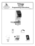
DK3000
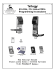
Downloading Software for
the Trilogy® Line of
Standalone Access Control
Systems
PDK3000
ETDL
PDL3500
PDL4500 - "RESIDENCY" LOCK
DL3500
DL4500 - "RESIDENCY LOCK"
DL3000
DL4100 - "PRIVACY LOCK"
PDL3000
PDL4100 - "PRIVACY" LOCK
AL-DTM
DATA TRANSFER
MODULE
AL-IR1
INFRARED PRINTER
AL-PRE PROX
CARD READER/
ENROLLER
PL3000
1
Table of Contents
DL-Windows Features ............................................................................................................................... 3
Supported Products................................................................................................................................... 4
Product Communication Examples............................................................................................................ 5
Overview ................................................................................................................................................... 6
Terminology .............................................................................................................................................. 7
DL-Windows Buttons ................................................................................................................................ 9
DL-Windows Main Menu ......................................................................................................................... 10
Quick Start Checklist ............................................................................................................................... 11
DL-Windows Software Installation ........................................................................................................... 12
Upgrading From a Previous Version of DL-Windows ............................................................................... 13
DL-Windows Security Features ............................................................................................................... 14
Create a New Account and Add Locks .................................................................................................... 15
Add Users with the Global Users Screen................................................................................................. 16
Enroll ProxCards® with the AL-PRE ........................................................................................................ 17
Creating Schedules and TimeZones ....................................................................................................... 20
Send/Receive Information to/from the Lock ............................................................................................. 21
Sending Data directly to the Lock from the PC ........................................................................................ 22
Receiving Data from the Lock ................................................................................................................. 23
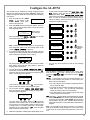
Configure the AL-DTM ............................................................................................................................ 25
Send Data from DL-Windows to the AL-DTM .......................................................................................... 26
Send Data from the AL-DTM to the Lock ................................................................................................. 27
Receive Event Logs with the AL-DTM ..................................................................................................... 28
"Global Users" Screen - Field and Button Definitions ........................................................................... 29
"Set Administrative Users" Screen - Field Definitions ........................................................................... 30
"Lock Data" Screen - Field Definitions .................................................................................................. 31
"Event Log Viewer" Screen - Field Definitions ...................................................................................... 32
"Programmable Features" Screen - Options tab ................................................................................... 33
"Programmable Features" Screen - Customize DST ............................................................................. 34
"Programmable Features" Screen - Relay Functions tab....................................................................... 35
"Programmable Features" Screen - Remote tab.................................................................................... 36
"Programmable Features" Screen - 4000 Series tab ............................................................................. 37
"Schedule-TimeZone" Screen - TimeZones Area ................................................................................. 38
"Schedule-TimeZone" Screen - Schedule Entry Area ........................................................................... 39
"Schedule View" Screen - Program Field Definitions ............................................................................. 40
"Options" Screen - Program Field Definitions ........................................................................................ 41
Exporting and Importing Data .................................................................................................................. 42
Transferring Account Files Between PC's ............................................................................................... 43
"DTM 3 Support" Screen - Program Field Definitions ............................................................................ 44
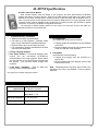
AL-DTM Specifications ............................................................................................................................ 45
Compact and Repair the Database ......................................................................................................... 46
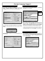
Foreign Language Support ...................................................................................................................... 47
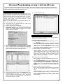
Advanced Programming .......................................................................................................................... 48
Advanced Programming--Group 1 Activated Events ............................................................................... 49
Appendix A
AL-DTM Communications with the PL3000 locks .................................................................................... 51
Appendix B
"Programmable Features" Screen (PL Series) - Options tab (Version 3.5.6) ....................................... 53
Glossary .................................................................................................................................................. 54
Warranty ................................................................................................................................................. 56
2
DL-Windows Features
up to 2000 locks of the same lock type. Note: All
models can be cloned into all other models, with
the following exceptions: DL2800 and DL3000
locks can only clone each other, and the DL3500
can only clone itself.
Basic Functions
When installed on an IBM compatible desktop or notebook computer, DL-Windows can provide the following
functions:
• Create a new Lock Program
• Edit an existing Lock Program
• Send a Lock Program to a lock
New Features for Version 3.6.0
•
• Receive a Lock Program from a lock
• Retrieve an Audit Trail (Event Log records) from a lock
• Configure an AL-DTM to transfer data to multiple
locks
• Read ProxCards® using the ProxCard® Reader (ALPRE)
Features
• Fully Integrated Help File Systems and Online Manual
• Supports up to a 2000 User Database
• Allows Viewing of 40,000 Event Audit Logs
• Account and Database Utilities
• Compact and Repair Database
• Import / Export
• Rename Accounts
• Search Feature-to Quickly and Easily Find Users
Features for Version 3.5.X
(Note: The "X" denotes any release of version 3.5).
• LockID (see page 21). "Door Numbers" are now
referred to as "LockID's", with Accounts in DLWindows v3.5.X now able to accommodate up to a
maximum of 2000 locks. Each LockID is unique
to each lock, ensuring the validity of data and that
each lock is matched to the correct data when programmed.
• Global Administrative Users (see page 30). A
new "Set Administrative Users" button simplifies
the organization of those special Users possessing
a greater range of programming abilities. All Users
designated as "Administrative Users" will be identical for all locks within the Account.
• Individual Group Assignments (see page 16)
Group Support: A single user can be assigned to
different Groups in different locks within an Account
• Creating and Cloning Multiple Locks (see page
15). Allows you to save time when creating a new
lock. Cloning duplicates all schedules and Users
programmed from an existing lock. You can clone
Daylight Saving Time (see page 33-34). The
manner in which Daylight Saving Time (DST) is
observed varies with location, therefore the DST
adjustment is fully flexible to accommodate these
regional differences.
CHANGES FROM PREVIOUS EDITION
The following changes have been made to this manual
(OI237H) since the previous edition (OI237G):
• Added the ability to backup all Accounts into a single
•
•
•
•
directory (accessed from the Tools menu) See
page 46.
The Social Security field of the Global Users
Screen is now a custom field, i.e. the field name is
now assignable through the Options screen and allows a 15-character entry. See pages 16, 30 and
41.
User name sorting in the Global Users Screen has
been added through a drop down above the Names
grid. Multiple sorting options have been added including sorting on the custom field. See page 29.
The ability to add selected users to Groups and Levels has also been added. See page 16.
Added special Daylight Saving Time configuration
settings for the DL/PDL1300 lock, located in the Programmable Features screen, Options tab. (See
pages 33-34).
The following screens have been changed:
• Global Users (see page 29)
• Set Group Assignment (see page 16)
• Set Level Assignment (see page 16)
• Set Administrative Users (see page 30)
• Features – DST (see pages 33-34)
• Options (see page 41)
• Tools menu (see page 10 and 46)
3
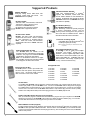
Supported Products
PDL3000 / PDL3500 / PDL3300
2000 User Codes/ProxCards® or ProxKey®
keyfobs, 500 Schedules, 40,000 Audit Trail
Events. Refer to WI1021 for more information on
features. DL-Windows also supports the similar
PDL3500 mortise lock and PDL3300 Door Ajar
lock with Prox capability.
DK3000 / PDK3000
Relay-only locking device, 2000 Users, 500
schedules, 40,000 Audit Trail events. The
PDK3000 adds Prox capability.
DL3000 / DL2800
300 User Codes, 150 Schedules, 1600 Audit
Trail Events. Refer to OI224 for more
information on DL3000 features.
DL-Windows also supports the similar
DL2800, which supports 200 Users.
DL3500 / ETDL / ETPDL
DL3500: 300 User Codes, 500 Schedules,
40,000 Audit Trail events. Refer to WI1005
for more information on DL3500 features.
ETDL: 2000 User Codes, 500 Schedules,
40,000 Audit Trail Events. ETPDL adds Prox
capability
DL / PDL4100 ("Privacy")
DL / PDL4500 ("Residency")
The "Residency" feature is specially designed
to prevent unintentional lock-out, and the
"Privacy" feature is designed to deny access to
other users after an individual enters. Refer to
WI1194 and WI1195 for more information.
HID
HID CORPORATION
ProxCard® / ProxKey® Keyfob
Compatible with most HID ProxCards® and
ProxKey® keyfobs (26-37 bits).
Note: ProxCard® and ProxKey® are trademarks of the HID©
Corporation.
Prox Card Reader/Enroller (AL-PRE)
An AL-PRE is used to quickly enroll multiple
ProxCards® and ProxKey® keyfobs into DLWindows. Use the supplied 9-pin DB9 to DB9
serial cable to connect the AL-PRE to your computer’s serial COM port. Compatible with most
HID ProxCards® and ProxKey® keyfobs (37 bits
or less). For PDL series locks only.
Data Transfer Module (AL-DTM)
The AL-DTM allows the transfer of Lock
Programs and other data between DL-Windows
and locks. See page 45 for detailed AL-DTM
specifications and feature descriptions.
Note: For DL-Windows versions 3.5 or higher,
the AL-DTM-III must be used, but will be referred
to as simply the "AL-DTM" in this manual.
All supported locks:
Infrared Printer (AL-IR1)
An AL-IR1 printer is used to print Audit Trails
and User Code lists (where used) without the
need for a PC. Its infrared reader means no
cable connection to the lock is needed.
•
•
•
•
•
•
•
DL1200
DL1300
DL2800
DL3000
DL3200
DL3500
DL4100
•
•
•
•
•
•
•
DL4500
DK3000
ETDL
PL3000
PDL1300
PDL3000
PDL3300
•
•
•
•
•
PDL3500
PDL4100
PDL4500
PDK3000
ETPDL
AL-PCI2 Cable
An ALARM LOCK AL-PCI2 cable is required to communicate between your computer’s RS-232 serial communications port (COM 1-4) and the AL-DTM or lock. One end of the AL-PCI2 cable is designed to be plugged
into a DB-9 male 9-pin serial COM port. If your computer has a 25-pin COM port only, a 25-pin to 9-pin adapter
must be used. The other end of the AL-PCI2 cable features a 2-pin banana plug connector which is polarity
sensitive--the TAB (marked “GND”) side must be plugged into the lock’s black (left) terminal.
Double-ended Mini Banana Plug Connector (supplied)
After you create the program in DL-Windows and transfer the program from your computer to an AL-DTM,
transfer the program from the AL-DTM to the lock(s) via a double-ended mini banana plug. You can also
use this cable to transfer the Lock Program from your lock to an AL-PRE.
DB9 to DB9 Serial Cable (supplied)
Enroll ProxCards quickly into DL-Windows, then transfer this new ProxCard® data from the computer to the
AL-PRE via this 9-pin DB9 to DB9 serial cable. Once the data is in the AL-PRE, you can transfer the data
to the lock via the double-ended mini banana plug (see above), thus avoiding the need to use an AL-PCI2
cable for this process.
4
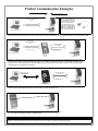
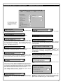
Product Communication Examples
Send to lock
Receive from lock
AL-PCI2 CABLE
CONNECT TO SERIAL PORT
(COM 1-4)
If your computer does not
have a serial COM port (DB9 male) available, you can
plug your AL-PCI2 cable
into a special USB to RS232 cable. Order part PCIUSB for the USB to RS-232
cable only, or ALPCI2-U for
both the USB to RS-232 cable and an AL-PCI2 cable).
NOTE: OBSERVE TAB DIRECTION WHEN
INSERTING CABLE INTO LOCK
IBM COMPATABLE
LAPTOP OR DESKTOP PC
PDL3000 LOCK
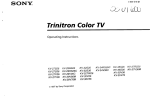
Scenario 1 Create the program in DL-Windows on your computer, then transfer the program from the computer directly to the lock via an AL-PCI2
cable. Enter the User 298 User Code to send or receive data to of from DL-Windows. When no COM port exists, use a USB to RS-232 cable.
AL-PCI2 CABLE
CONNECT TO SERIAL PORT
(COM 1-4)
DOUBLE-ENDED MINI BANANA
PLUG CONNECTOR
NOTE: OBSERVE TAB DIRECTION WHEN
INSERTING CABLE INTO LOCK
NOTE: OBSERVE TAB DIRECTION
WHEN INSERTING CABLE INTO ALDTM AND LOCK
IBM COMPATABLE
LAPTOP OR DESKTOP PC
AL-DTM DATA
TRANSFER
MODULE
PDL3000 LOCK
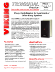
Scenario 2 Create the program in DL-Windows and transfer the program from your computer to an AL-DTM (via an AL-PCI2 cable)…
then transfer the program from the AL-DTM to the lock(s) (via a double-ended mini banana plug). The hand-held AL-DTM is useful
because you do not have to transport (or find electricity for) your computer. Data can also flow in reverse, from the lock, through the
AL-DTM, back to the computer for examination.
CONNECT DB9 CABLE
TO COMPUTER SERIAL
PORT (COM 1-4)
DOUBLE-ENDED MINI BANANA
PLUG CONNECTOR
DB9 to DB9 Serial
Cable (supplied)
NOTE: OBSERVE TAB DIRECTION
WHEN INSERTING CABLE INTO ALPRE AND LOCK
IBM COMPATABLE
LAPTOP OR DESKTOP PC
AL-PRE PROXCARD READER/
ENROLLER
®
PDL3000 LOCK
®
Scenario 3 Enroll ProxCards quickly into DL-Windows, then transfer this new ProxCard data from the computer through the AL-PRE
to the lock (thus avoiding the need to use an AL-PCI2 cable). For PDL series locks only.
AL-IR1
INFRARED PRINTER
PDL3000 LOCK
Scenario 4 Use the AL-IR1 Infrared printer to print your lock’s audit trail (event log), User Code
list, clock settings and software version. No cable required.
NOTE:
The AL-PCI2 cable is designed to be used on a 9 pin serial COM port. If your computer has a 25 pin COM port, a 25 pin to 9 pin adapter must be used.
Warning: Polarity MUST be observed when connecting cables to the lock. The tab (-) must plug into the negative (black) hole.
5
Overview
Why Use Software Inside a Lock?
With ordinary door locks, the need to make physical copies of metal keys and distributing them can be a huge organizational and
financial task -- and what will you do if someone causes a security breach by losing their key? The answer lies in the advantage
of software.
Software (also called firmware) is not "hard" or "fixed" like hardware is. Software is flexible and changeable to your needs. Software exists inside your Alarm Lock™ series lock, and can be programmed (and re-programmed again and again) to suit your
changing requirements. No more metal keys to distribute...instead, distribute User Codes -- and delete them from the software
when needed. (A User Code is the software equivalent of a metal key--it is a series of numbers the User presses into the lock
keypad keys to unlock the lock). (Note: The PL3000 does not have a keypad---see WI1280).
Preparing to Program your Lock
There are two ways to make changes to the software inside your lock--either by using the lock keypad or by using DL-Windows.
Although using DL-Windows makes programming faster and easier, we recommend you familiarize yourself with the general
concepts of keypad programming as well. The first step to programming your lock without DL-Windows requires that you enter
something called "Program Mode".
What is Program Mode?
The software inside the lock has only two "modes"--Normal Mode and Program Mode. When you want to make changes to the
lock program, you enter Program Mode. When you finish programming and wish to put the lock into use, you exit Program Mode
to enter Normal Mode.
Use the keypad to enter Program Mode by pressing the Master Code of the lock that was set at the factory (see the Programming Instructions of the individual lock for more information). The Master Code is like a secret password that allows you to enter
Program Mode. But since all locks are identical and leave the factory with the same Master Code, the factory Master Code is not
very secret and should be changed to your own personal Master Code. This way, only YOU can enter Program Mode and make
changes to the lock programming.
With most locks, changes to the lock are organized by their Function Number. Want to change the date inside the lock? Use
Function Number 38. Want to add a User Code? Use Function Number 2.
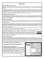
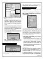
With DL-Windows, you first use the various DL-Windows computer screens to make the programming selections, then later you
send the programming selections from your computer to the lock's memory. You do this by clicking the
Comm button in DL-Windows and selecting Send to Lock (see image at right). You can also use DLWindows to receive programming from a lock, allowing you to observe the lock programming inside DLWindows. Because your lock can be programmed using DL-Windows, and then using the keypad, DLWindows will detect changes made by the keypad, and will alert you to these discrepancies in a screen named Lock Differences. See page 23 for more information.
The Global Users Screen
Perhaps the most significant part of DL-Windows is the Global Users screen and the concept of an "Account". An Account can
be thought of as simply a building in which Alarm Lock locks are installed. If there are 55 locks in this building, and one person
needs access to all of those locked doors, it would be convenient to assign that person one User Code to remember, and to enter
their name in the computer only once---rather than having to enter their name 55 times. The Global Users screen was developed
for this very reason--to support the concept of an Account, allowing a User Name to be entered only once, and to allow you--the
person in charge of the locks--to sit back and assign this User to all locks
in an Account with just a few clicks of the computer mouse.
Turn the page and learn the special terminology used with your lock, then
use the Quick Start checklist on page 11 to help you get started.
DL-Windows System Requirements
This application has been tested and approved for an IBM-compatible P4
1.6 GHz computer with 256MB RAM and a minimum of 100MB of hard
drive space running Microsoft Windows 98, 2000 or XP with one unused
RS-232 Serial Communications port (COM 1-4) required. If a COM port
is unavailable, please contact customer support for one of our USB
adapters (PCI-USB or ALPCI2-U). Depending on your system demands, a slower PC may function properly but with significant user interface problems, including long intervals for the system to respond.
Global Users Screen
6
Terminology
DL-Windows
DL-Windows is a computer program that allows you to program
your ALARM LOCK T3 Security Lock. You do not need DLWindows to program your lock, but it makes programming much
faster and easier. With DL-Windows, you can quickly create Lock
Programs (programs that make the lock perform its many
functions) add multiple Users (who have access), add ProxCards®
and ProxKey® keyfobs, retrieve event logs, and create Schedules.
The benefit of DL-Windows is that it allows you to set up all lock
programming in advance (on your computer), and then send the
information to the locks at your convenience.
TimeZone screen to create these TimeZones, and once created,
you can link events to these TimeZones. Note: The ScheduleTimeZone screen is "Global"--when a new TimeZone is created, it
can be used for all locks in an Account. For more information, see
page 20.
Schedules
ALARM LOCK makes a variety of computer interfaced
microprocessor-based programmable keypad-entry and
ProxCard® security locks: DL3000, DL3500 and PDL Series
Access Control Locks. DL Windows works with them all.
Your lock can be programmed to maintain a schedule in which
certain events can occur automatically. For example, you can
program the lock to allow Groups of Users (with their User Codes)
access ONLY during specific business hours. With another
example, you can program another lock to UNLOCK at 9am,
LOCK at noon for lunch, UNLOCK at 1pm, and LOCK again at
5pm--every weekday.
As you can see, many different
combinations of Schedules can be created to suit the needs of the
Users. First you create TimeZones (see above) with the
Schedule-TimeZone screen. Next you create events and link
them to your TimeZones (also with the Schedule-TimeZone
screen). When finished, you can view your schedule in the
Schedule View screen.
Users
Programming Levels
This Users Guide to DL-Windows will guide you through all
aspects of the lock--from the software installation procedure
through the creation of a Lock Program, from the transfer of lock
programming to the viewing of lock event logs.
A User is a person who is authorized to simply use or make
certain programming changes to the lock. This User can be
anyone--from a one-time visitor (who will almost certainly have no
authority to make changes) to the owner of the building in which
the lock is installed (who will probably wish to have total authority
to make changes). Most PDL Series locks can hold up to 2000
Users in its programming memory, and each User possesses a
pre-defined level of authority--a Programming Level--as to their
ability to use or make changes to the lock.
Lock Program
A Lock Program contains the instructions that a lock uses to
perform its various functions. You can use DL-Windows to create
a Lock Program on your computer, and then transfer and store the
Program in the circuitry contained inside the lock itself. The Lock
Program is essentially a computer database file that maintains
feature settings, schedules, audit trails, etc. Using DL Windows,
Lock Programs can be created with default information, edited on
your PC, and then sent to (and even received from) locks.
The Lock Program consists of 4 areas: User Codes, Features,
Time Zones, and Schedules, all defined below:
User Codes
Also called User Access Codes or PIN No. Codes, User Codes
are numbers the User enters into the lock keypad to unlock the
lock. Using DL-Windows, Users are matched with their own
individual User Codes. The User Codes are part of the Lock
Program, and the Lock Program is stored in the lock circuitry
awaiting the Users to key in their User Codes.
Features
Your lock is designed to support several options and functions.
Using the Programmable Features window, you can select the
features you wish to activate, such as if the lock will automatically
adjust for Daylight Saving Time in the spring and autumn, or if the
lock sounder should be disabled or enabled.
TimeZones
Events (recorded lock activities) can be programmed to occur at
certain times. It is these times (for example, “every Tuesday at
5PM”) that are referred to as TimeZones. You use the Schedule-
The Programming Level defines the range of programming tasks a
User is allowed to perform. For most locks, the higher the Level,
the more programming tasks the User is allowed (with the Master
allowing ALL tasks for all locks).
Note: For the DL2800/DL3000 series locks, the Programming
Levels are slightly different. See "Set Level Assignment"
explanation on page 30 and also the DL2800/DL3000
programming manuals for more information.
Note: Since the Programming Level is closely associated with the
type of User and their abilities, a User who holds a certain
Programming Level is sometimes referred to by their “User Type”.
For example, some locks can hold up to 2000 Users in its
programming memory, and each User is associated with a User
Number (see definition of "User Number" on the next page) and
therefore a specific Programming Level, as shown in the following
list of "Administrative Users":
Master: Always associated with User Number 1. Is always
enabled and can program all functions. (Abbreviated as
Programming Level = M).
Installer: Always associated with User Numbers 2 and 3. Can
program all functions except changing the Master Code.
(Abbreviated as Programming Level = 4).
Manager: Always associated with User Numbers 4, 5, and 6.
Can program all functions except functions relating to lock
configuration. (Abbreviated as Programming Level = 3).
Supervisor: Always associated with User Numbers 7, 8 and 9.
Can only program functions relating to day to day operation.
(Abbreviated as Programming Level = 2).
Print Only Users: Always associated with User Numbers 10 &
11. Restricted to print event logs only. No other programming
ability allowed. (Abbreviated as Programming Level = 1).
Basic Users: Always associated with User Number 12 and
higher (except 297-300). No programming ability allowed.
Programming Levels are hierarchical--higher levels are allowed to
do anything the levels below them can do. For example, if you are
a Manager, you are allowed to do anything that Supervisors, PrintOnly Users and Basic Users can do in addition to those tasks
allowed for Managers (Level 3). (Not applicable to the DL2800/
DL3000).
(continued)
7
Minimum Required Program Level
This Programming Level abbreviation is the minimum programming
level required to access the particular Function. (The higher the
level number, the more programming tasks the User is allowed,
with Master allowing all tasks).
In this manual, Programming Levels are abbreviated as follows: M
= Master, 4 = Installer, 3 = Manager, 2 = Supervisor, 1 = Print Only
Users
User Numbers
(User Number = Location Number = User Location = Slot in Lock)
User Numbers are used and are significant within each individual
lock only. The User Number determines the Programming Level for
each User. For example, many locks can hold up to 2000 Users in
its programming memory. This memory can be thought of as
simply a numbered list from 1 through 2000. Each entry in the list is
represented by a User Number. Therefore, where a User is located
in this list--their User Location--is a commonly used description of
their User Number. Because of their similarities, a User Number,
User Location and Location Number can be used interchangeably.
In some DL-Windows screens, the word "Slot" is also used.
Since User Numbers are fixed, knowing a User Number will specify
the associated Programming Level, and will in turn indicate a User’s
programming abilities. For example, User Number 1 is always the
Master, who can perform all programming tasks.
Programming Levels are hierarchical--higher levels are allowed to
do anything the levels below them can do. For example, if you are
User 2, you are allowed to do anything that Users 3 through 2000
can do. Some DL series locks can hold up to 300 Users in its
memory, however, the definition of a User Number is the same for
these locks as well. (Not applicable to the DL2800/DL3000).
Groups
With many lock applications, it is convenient for large numbers of
similar Users to be grouped together. Placing Users into Groups
(by assigning them specific User Numbers) allows large numbers of
Users to be controlled all at once rather than individually--saving
time and effort. Groups are controlled via schedules, and a typical
example involves enabling or disabling a Group at a certain time.
For example, if you wish to add a User to Group 1, assign this User
a User Number between 51 and 100. Default Group associations
(see the lock programming instructions for details) can be changed
if needed to allow Groups larger than the default number. In
addition, a single User can be assigned to different Groups in
different locks within an Account. See page 16 for more
information.
Users 297-300
Many locks have Users assigned to User Numbers 297, 298, 299
and 300. These User Numbers have special abilities, as follows:
User 297: Quick Enable User 300
User 297 possesses the unique ability to enable the User Code
associated with User 300. User 297 does this by first entering
their own User 297 User Code into the lock keypad. When User
300 subsequently enters their User 300 User Code, the lock
allows access (for one time) and then the User 300 User Code
becomes disabled.
For example, you wish to allow one-time access to a temporary
worker. Simply enter the User 297 User Code into the lock
keypad. Later, when the temporary worker enters the User 300
User Code into the lock keypad, the User 300 User Code allows
8
access (for one time only) and then becomes disabled. Later, if
you wish to grant the temporary worker re-access, simply re-enter
the User 297 User Code and the User 300 User Code will be reenabled (again for one time only). Note: User 297 is not used
with the DL2800/DL3000 locks, but Function 9 can be used with
the DL2800/DL3000 locks as an alternative.
User 298: Quick PC Access Code
Entering the User Code for User 298 enables that User to send
data to or from the lock. Therefore, User 298 can activate what is
the equivalent of Function 58 in Program Mode (see the lock
programming instructions for details), without the need to enter
Program Mode nor the need to know the Master Code of the lock.
An AL-PCI2 cable with a PC is required. NOTE: The User Code
for User 298 is not an Access Code and is not used with the
DL2800/DL3000 locks.
User 299: AL-DTM Code
This is the only User Code that will initiate data transfer with the
AL-DTM--and without allowing the User to pass through the door
(the User Code for User 299 is not an Access Code). An AL-PCI2
cable and an AL-DTM (first programmed by the computer via the
DTM screen in DL-Windows) is required.
User 300: Temporary Access
Temporary access User Code enabled by User 297. For
example, User Code 300 is sometimes used for guard tour duties.
See User 297: Quick Enable User 300 above. Note: User 297 is
not used with the DL2800/DL3000 locks, but Function 9 can be
used with the DL2800/DL3000 locks as an alternative.
Accounts
Technically, an Account is a DL-Windows computer database file
that allows you to organize and maintain multiple lock installations.
But in practical terms, an Account is often named after the building
or company location in which a lock or multiple locks have been
installed. For example, the Account Name might be “Overbrook
Hospital” and listed in that Account are the 4 locks you just installed
on the 7th floor. In DL-Windows, Accounts can be created, edited,
cloned and deleted. The benefit of an Account is that it allows you
to add the name of a User ONCE and then assign that User to
multiple locks within a building--rather than having to enter and reenter the same User information again and again for each lock in
your building. Enter the name of the User once in the Global Users
screen, then sit back and assign that User to the locks you wish -with just a click of the mouse.
Global ID Numbers
Note: The Global ID number can be hidden from view. See page
16 to show or hide the Global ID number.
A Global ID is used within the DL-Windows Global Users screen
and is Account specific--it remains constant within Accounts only. A
Global ID is not related to User Numbers nor Programming Levels.
The Global Users screen simply lists all potential Users within an
Account (which can contain up to 2000 locks).
DL-Windows keeps track of each "Global User" listed in the Global
Users screen by use of the Global ID number, but its significance
ends there--it acts as an internal designation only.
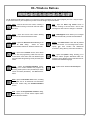
DL-Windows Buttons
The DL-Windows toolbar (above) allows you to open the screens and dialogs you will need to program your lock. It may be helpful
to open each screen on your computer as you read. From left to right, they are as follows:
Open - View the Account Tree column, revealing a
hierarchical tree listing of Accounts and locks within
Accounts.
Log - Open the Event Log Viewer screen to
examine a listing of all lock events --from a User
entering their User Code to a change in a schedule.
Close - Close the Account Tree column allowing
more room for other DL-Windows screens.
DTM - DTM Support screen allows you to configure
and communicate with your Data Transfer Module.
Comm - Opens the Receive from Lock dialog or the
Send to Lock dialog.
Allows for direct
communication between DL-Windows and the locks.
Global - The Global Users screen lists all potential
Users in an Account. You can assign Users to locks,
specify their User Location and add/remove
ProxCards® (along with any other User information).
Lock - Opens the Lock Data screen, which allows
you to "view the programming" inside the lock, such
as the names of the Users, their User Numbers (and
their associated Programming Levels) and their User
Codes.
Sched - Opens the Schedule-TimeZone screen,
allowing you to create automatic lock programs by
choosing certain points in time (TimeZones) to which
events are linked (Schedules). See SchV button,
below.
Opt - Opens the Options dialog, allowing you to
determine various program alternatives within DLWindows, specify StartUp screens and select the DLWindows user interface language.
Help - Opens the DL-Windows On-line Help file.
SchV - Opens the Schedule View screen, revealing
a compiled view of all TimeZones and Schedules
that were created using the Schedule-TimeZone
screen .
Feat - Opens the Programmable Features dialog,
which allows you to choose various Options within
the DL-Windows software.
9
DL-Windows Main Menu
Menu System and Shortcut keys
The sub-menus within the DL-Windows Main Menu bar
can be activated by clicking the mouse or via shortcut
keys. They are as follows:
Global Users
Help Menu (Alt + H)
Contents - (Can also press F1)
File Menu (Alt + F)
Exit - Quits and closes the application.
Index - (Can also press F2)
Find - (Can also press F3)
What's This Help
Options Menu (Alt + O)
Show Options
DTM3 Help Screen
DL3000 Lock
DL3500 Lock
Tools Menu (Alt + T)
Manage Users
Set Security Password
Edit Languages
Com Port Setup and Test
Import CSV File
Import CSV File From Excel
Import CSV File From DL-Windows
Export Active Account to CSV
Import a Single ADF Account File
Backup Accounts
Check for Ambush Code Conflict
Compact and Repair Database
Window Menu (Alt + W)
Cascade - (Can also press F5)
Lock Data
Schedules
Schedule View
Features
Event Log Viewer
DTM
10
PDL3000 Lock
Alarm Lock On The Web
Help on Help
About
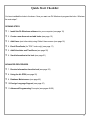
Quick Start Checklist
You have installed the locks in the doors. Now you want use DL-Windows to program the locks. What are
the main steps?
OPENING STEPS
❒ 1. Install the DL-Windows software into your computer (see page 12)
❒ 2. Create a new Account and add locks (see page 15)
❒ 3. Add Users (and other data) using Global Users screen (see page 16)
❒ 4. Enroll ProxCards (for "PDL" locks only) (see page 17)
❒ 5. Add Schedules and TimeZones (see page 20)
❒ 6. Send Information to the lock (see page 21)
ADVANCED PROCEDURES
❒ 7. Receive Information from the lock (see page 23)
❒ 8. Using the AL-DTM (see page 25)
❒ 9. Database Maintenance (see page 46)
❒ 10.Foreign Language Support (see page 47)
❒ 11.Advanced Programming Concepts (see pages 48-50)
11
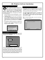
DL-Windows Software Installation
Installing DL-Windows Software
Note: Uninstall any previous version of DLWindows before Installing DL-Windows. Account
data associated with previous installations will
remain intact, with the exception of Prox devices
(see warning below). Use the Update Database
utility on databases created using prior versions of DLWindows. Please read the readme.txt file for the latest
information about DL-Windows. See page 6 for DL-Windows
System Requirements.
1. Place DL-Windows CD into the CD-ROM drive. The DLWindows InstallShield Wizard will automatically begin the
installation process.
2. If the Wizard installation process does not automatically
begin, click Start, Run and type the following: D:\Program
\English\setup.exe, where D is the Drive Letter associated
with the CD-ROM. For installations other than English,
please read the Setup.txt file located on the installation
CD.
3. The Installation program will prompt you regarding the
ReadMe file, and the installation destination folder on your
hard drive. When installation is complete, you will be
asked to reboot your computer.
Starting DL-Windows
Click Start, select Programs, select the DL-Windows Program
Group, then click on DL-Windows 3.X.X. After a few moments,
the following screen will appear:
Open button
Right mouse-click here
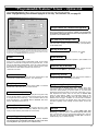
When opening DL-Windows for the first time (without any
Accounts), the popup will appear, directing you to right-click in
the white pane (the Account Tree area at the left) and select
New Account. From this main screen you can create new
Accounts, add locks to the Accounts, transfer data to and from
locks, and perform all other needed tasks. Before starting, you
will first need to select a Com port through which (via a wire
cable) your computer and the locks will be connected.
12
AL-PCI2 Setup
The comm port refers to a serial port located at the back of your
computer that is used to communicate with the lock. Connect
an AL-PCI2 cable (or the supplied 9-pin DB9 to DB9 serial
cable) to an unused comm port at the back of your computer.
Leave the other end of either cable unconnected.
Select Tools, Comm Port Setup and Test. This Comm Test
utility allows the DL-Windows software to detect which Com
Port is connected to the cable. The first comm port that passes
the DL-Windows automatic detection test will be selected.
When finished, click Exit.
Note: If you are not using COM1, you must run this utility to
identify the active comm port.
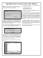
Upgrading From a Previous Version of DL-Windows
NOTE: This section applies only to Accounts and locks created with previous versions of DL-Windows. For new Accounts, please ignore the following instructions.
When selecting your database files, the Files of type pulldown menu lists two file types:
• New DL-Windows Index files
• Old DL-Windows Index files
The Old file type is listed as AL3000.MDB and the New file
type is listed as AcctList.adf.
After selecting the file type, the Upgrade Utility determines
which operation needs to be performed (either Update or Import) and enables the appropriate button to perform the
needed operation. Regardless of the operation performed, the
Upgrade Utility will create a new sub-directory named Original
Files containing a backup of your original unchanged Account
files. Should your upgrade operation not complete properly,
the application will restore these original files back to the main
directory.
Open the Import Utility application by clicking Start, Programs,
DL-Windows, Import Utility. The Import Utility application is
independent of DL-Windows and allows the database files
(Accounts) of previous versions of DL-Windows to be upgraded
to the latest version of DL-Windows.
Once Update or Import is selected, the Upgrade Utility will
start to run and, depending on the file sizes and quantity, the
process may take a while. Some older Accounts with many
locks could take more than ten minutes to complete, while others may only take a few seconds.
When running old Account database files in DL-Windows, you
may encounter a pop-up message (shown below) requesting
you run the Import Utility to update your Account files:
When the Upgrade Utility is complete, a message box appears
indicating the status of the upgrade.
When first started, the Import Utility application defaults to the
directory where your current working DL-Windows files are located (this directory is set from the DL-Windows Options
screen). Note: If your computer stores your database files in
more than one directory, you must run the Import Utility and
update the files in each of these directories.
Click the Open button to select the directory the Import Utility
will use.
13
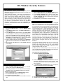
DL-Windows Security Features
Security Features in DL-Windows
The DL-Windows software provides security and protection
features to restrict unauthorized persons from accessing your
DL-Windows program.
When starting DL-Windows, a user name and password are
required to access the program. Creating user names requires a User Type be selected, (either Operator or Administrator). This User Type determines the range of tasks allowed
within DL-Windows. Creating authorized users should be the
first step in programming the DL-Windows software. Note:
For Operators, all administrative functions are grayed-out
within both the Global Users screen and the Options screen.
In addition, the functions listed below are accessible by Administrators only:
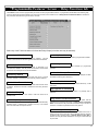
Adding Users (for access to DL-Windows software)
1. Click Tools, Manage Users to open the Manage Users
screen.
2. In the Manage Users screen, click Action, Add User (or
press CTRL+A).
3. In the Add User dialog (shown below), type a User Name
and a Full Name in the fields provided (the User Name will
appear on the Log-On screen when starting DL-Windows).
4. Select the access level by checking either Operator or Administrator in the User Type area. Users can be created
but disabled by simply un-checking Enable User.
5. Enter a password (at least 4 characters) in the Password
field and re-type the password in the Confirm field to verify.
6. When finished, click OK to save, or click Cancel to discard
your changes.
Change an Existing Password
1. Click to highlight the user in the Manage Users screen,
then click Action, Set Password (or press CTRL+ P).
2. In the Change Password dialog, type the existing password in the Old Password field, type a new password in
the New Password field and re-type the same new password in the Confirm field.
3. Press Enter on your keyboard to accept the changes.
Security Password
DL-Windows can utilize a Security Password to safeguard
against an unscrupulous person with knowledge of your ALDTM or PC download code. The Security Password prevents
an unauthorized user from reprogramming your installed locks
with their own copy of DL-Windows. Entering this password
into DL-Windows prior to initial programming of your locks
copies the password to a special area within the locks. The
password never needs to be entered again. Subsequent communication between DL-Windows, the AL-DTM and your locks
will automatically check for this password. If a different copy
of DL-Windows is used to program your locks, the passwords
will not match and no data transfer will take place. Once this
Security Password is stored within your installed locks, the
only way to change the Security Password is to erase all lock
programming for each lock (re-loading the factory default program) and then re-program each lock with a new Security
Password.
The Security Password ensures that only your copy of DLWindows can communicate with your locks. The Security
Password also makes certain that your copy of DL-Windows
must be used to program the AL-DTM in order for it to exchange information with your locks.
If desired (but not recommended), the use of more than one
copy of DL-Windows is possible--provided that the same password is entered in all copies of DL-Windows.
To program the Security Password:
1. Click Tools, Set Security Password.
Editing and Deleting Users
To edit existing users:
1. Either click Action, Edit User, press CTRL+ E, or doubleclick the user to open the Edit User dialog.
2. All existing information can be edited, and when finished,
click OK to save or click Cancel to discard your changes.
To delete an existing user:
1. Click to highlight the user in the Manage Users screen.
2. Click Action, Delete User or press CTRL+ D.
3. A confirmation popup will appear.
4. Click Yes to confirm the deletion, and click No to retain the
user.
14
2. Before entering any information, be sure to write down the
password to be used and save in a secure location. Once
the Security Password is entered into the program, it cannot be retrieved.
3. In the Set Security Password dialog, type a unique 6character password in the New Password field.
4. Re-type the same password in the Confirm field.
5. Click OK to save, or click Cancel to discard your changes.
Create a New Account and Add Locks
Create a New Account
When the DL-Windows screen first opens (below) click the Open
button located on the toolbar (upper left).
Press the Global button. The Global Users screen will appear
(below). Programming of User Codes, Programmable Features and
Schedules can now begin. Note: The screens that display on
StartUp can be selected under Options (press the Opt button).
Open button
Right mouse-click here
and select New Account
For Global Users screen field and button definitions, see page
29. For more information about Programming Levels and the
lock default tables, see the individual lock programming instructions for details.
(For new installations, a popup appears with directions). First press
OK to clear the popup, then (as directed by the popup) using your
mouse, right-click anywhere in this white box (the Account Tree area
at the left), and select New Account. The New Account dialog
opens.
Right Click Menu
New Account Description
Ent er t h e N ew Ac c o u nt
Description in the field shown at
right. The Account Description will
typically be the name of the company
or facility where a lock(s) will be
installed. Existing Accounts from
previous installations are also displayed. Click OK.
Delete an Account
If you wish to delete an Account, right mouse-click the name of the
Account and select Delete Account from the menu. A warning
popup will appear, and click Yes to confirm, and click No to cancel.
Add Locks to the Account
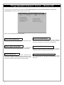
New Lock Description
After entering the new Account description, the New Lock dialog
automatically appears (shown below). Type the description of the
new lock, which will typically be the name of the door or department
in the facility. Select the Type of Lock to be programmed from the
drop-down list. When finished, click OK. Note: To add a new lock
to an existing Account, first open any existing lock in the Account,
then right-click in the white column and select New Lock. The Number of Locks to Create? field allows you to create multiple locks of
the same lock type. You can also "clone" locks (see next section
named "Right Click Menu"). Note: If you select a 4000 Series lock,
a special Mode of Operation Wizard dialog appears (shown below)
which allows you to select the type of lock programming for that
lock's application. See page 37 for more information about the Privacy and Residency Features in the PDL4100/DL4100 and
PDL4500/DL4500 series locks. Displayed below is a New Lock dialog used for adding new
locks, and a 4500
Series Mode of Operation Wizard dialog:
Select an Account, double-click a lock and right-click in the Account
Tree area. The following menu appears:
New Account and New Lock are described
above. Clone Account allows you to save time
when creating a new Account by duplicating all
information in an existing Account, with the exception of the lock information. Therefore, after
cloning an Account, new locks must be added,
but all names, Prox Card and other data in the
Global Users Screen will be duplicated. Select Delete Account
when you wish to remove an Account from DL-Windows permanently. Press Yes in the warning dialog only after you verify the Account to be deleted.
Clone Lock allows you to save time when creating a new lock.
Cloning duplicates in the new lock all schedules and Users programmed from an existing lock. When cloning, the Clone Lock
Data screen appears (below), which is very similar to the New Lock
screen shown previously. In the Number of Locks to Create? field,
click the drop-down list to clone up to 2000 locks of the same lock
type. Note: All models can be cloned into all other models, with the
following exceptions: DL2800 and DL3000 locks can only clone
each other, and the DL3500 can only
clone itself.
Select Delete Lock when you wish to
remove the lock from the Account
permanently. Press Yes in the warning dialog only after you verify the lock
to be deleted. Note: You cannot delete the last lock of an Account.
Select Rename when you wish to
rename the lock description of the
selected lock.
Sort Tree by Lock Name/LockID
For each Account listed in the white
pane (the Account Tree area at the
left), the locks for each Account can
be listed (top to bottom) either by the names of each lock
(alphabetically) or by the LockID number (sequential order as
added).
15
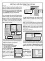
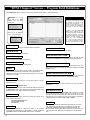
Add Users with the Global Users Screen
Overview
Select a Range of Users
The Global Users screen is used to enter all User information.
Users can be assigned to specific locks and assigned to Groups
within locks. All Basic Users are entered here as well as the Level
Assignment for DL3000/2800 locks. User lists can be imported from
other DL-Windows Accounts or from comma delimited formatted lists.
Administrative Users can be accessed through the Global Users
screen via the Add Administrative Users button. Please see page
29 for the Global Users screen layout and field descriptions.
To highlight a range of Users,
click in this column to select the
first User, press and hold the
SHIFT key, then click the last
User in the range…
...then rightclick and select
from any of
these options.
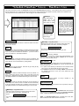
Add Users and User Codes
As shown in the image below, type the first and last name of a User
in the User Information Fields, and enter the remaining personal
information as needed. Note that the names entered in the First
Name and Last Name fields also appear in the User Name list.
Note: A specific PIN Number ("User Code") may be typed in the Pin
No. field for each User --or-- random User Codes may be autogenerated for one or many Users by right-clicking in the User Name
list. In addition, a Custom Field (located under the Pin No. field)
allows a customized field of up to 15 characters. This field is set in the
Options screen (click the Opt button) and once changed remains
identical for all locks in all Accounts.
User
Information
Fields
The LockID Grid
displays LockID
numbers
To select a range of Users, click to select the first User, press and hold
the SHIFT key, then click the last User in the range (you can also
press CTRL and click individual Users). Within the range of Users
highlighted, right-click in the highlighted area to display the menu
shown above. Click a selected action in the menu to perform the
action for the selected Users.
Random User Code Generation
Random User Codes may be generated for one or many Users.
(Note: To avoid User Number conflicts, it is recommended to first
assign specific User Codes to Users before selecting random User
Code generation). To generate random Codes, press and hold the
CTRL key, click the right arrow ("►") located to the left of the User
Name to select each User(s), then right-click and select “Generate
Selected New Codes”. You can select a range of Users (as
described above) and click Generate All New Codes to create new
codes for all Users.
Adding a User to a Group/Level
In the Global Users Screen, select a range of Users or click individual
Users as described in the section "Select a Range of Users" (above),
then click the Set Group Assignment button to display this screen:
In this example, for LockID #6,
double-click in a box (1-4) to
set the Group assignment for
this User.
Right-click menu in
the User Name list
Note: The ID column in the User Name list is used for identifying
Users in this screen only and is NOT associated with positions in
the Lock Data screen. For this reason, if displaying these
numbers is confusing, this column may be hidden using the
Options screen (see page 41 for more information).
The LockID Grid displays LockID numbers and is color-coded to
describe the state of the selected User:
• Green = User entered in the lock and enabled
• Red = User entered in the lock but disabled
• White = User not in the lock
Double-click on a LockID Grid number
to cycle through the colors of the
LockID number (from white to green to
red and back to white) thus adding,
disabling or removing a User as
needed. In this way, the LockID Grid
can be used to add a User to any lock
in an Account. One or multiple Users
can also be added to one or more locks
via the right-click menu in the User
Name list.
16
Lock Grid
To add a selected
User, double-click on a
LockID number box.
In the above dialog, rows represent Groups and columns represent
locks (the number above each column is the LockID number).
Double-click in the grid to add the User to a Group in a single lock
(hold down the Ctrl key to allow single-click entry). To save time,
check the appropriate check box to add the User to the same Group
in all locks. When finished, click Add Selected Users to These
Groups to add the selected Users to the Groups highlighted in
green. The same procedures apply to the Set Level Assignment
button and Set Level Assignment For User screen (note that
Levels are only associated with the DL3000 and DL2800 locks).
Administrative Users
The Add Administrative
Users button displays the
Set Administrative Users
screen.
Administrative
Users are the same for all
locks within an Account.
Enter information the same
way as if adding a basic
User.
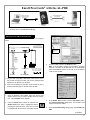
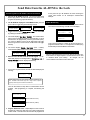
Enroll ProxCards® with the AL-PRE
CONNECT DB9 CABLE
TO COMPUTER SERIAL
PORT (COM 1-4)
DOUBLE-ENDED MINI BANANA
PLUG CONNECTOR
DB9 to DB9 Serial
Cable (supplied)
IBM COMPATABLE
LAPTOP OR DESKTOP PC
NOTE: OBSERVE TAB DIRECTION
WHEN INSERTING CABLE INTO
AL-PRE AND LOCK
AL-PRE PROXCARD READER/
ENROLLER
®
PDL3000 LOCK
®
®
Enroll ProxCards and ProxKey keyfobs quickly into DL-Windows, then transfer this new ProxCard data from the computer through the
AL-PRE to the lock. For PDL series locks only.
Setting up the AL-PRE Proximity Enroller
Connect the AL-PRE, lock and computer as shown in the figure
below:
AL-PRE -- Rear Panel
TO LOCK
TO COMPUTER
Use (1) 9 Volt Alkaline
Battery (Duracell MN1604 or
equivalent) or the 9V DC
Transformer described below.
Click here to
highlight the
User.
NOTE:
OBSERVE
TAB DIRECTION WHEN
INSERTING
CABLE INTO
AL-PRE AND
LOCK
DOUBLE-ENDED MINI BANANA
PLUG CONNECTOR
To lock
DB9 to DB9 Serial Cable
(supplied)
3.
On the AL-PRE, press the red Push On button.
Note: If the AL-PRE is inactive (no ProxCards® are being
read) for 5 minutes, the AL-PRE will turn off automatically.
Press the Push On button on the top of the AL-PRE to
“wake up” the AL-PRE.
4.
In the Global Users screen, click the Add Cards button.
The ProxCard Enrolling dialog opens. The AL-PRE is now
ready to accept Prox entries.
5.
In the ProxCard Enrolling dialog (right), check Enable ALPRE.
Optional: 9V DC Transformer:
Input: 120V AC, 60Hz, 8W
Output: 9V DC, 333mA min.
To computer
1. Plug one end of the DB9 to DB9 Serial Cable into the rear of
the AL-PRE and plug the other end into the selected serial
COM port in the back of your computer.
2. Insert a 9 Volt battery into the back of the AL-PRE, or plug a
9V DC transformer plug into the side of the AL-PRE.
Add ProxCards® and ProxKey® Keyfobs with the AL-PRE
1.
2.
Open DL-Windows, press Open, select the Account and
double-click the lock you wish to update with Prox information. The Lock Data screen appears.
Press the Global button (shown at right) and the
Global Users screen opens. Highlight the User by
pressing the Global ID column of the User you wish
to associate with the ProxCard® or ProxKey® keyfob.
(continued)
17
Note: All proximity information for the selected User will be removed from all locks in the Account. When the warning dialog
appears, press Yes to delete the proximity information.
Add Prox Information--Without the AL-PRE
Prox information
added for Dave Block
NOTE: You will need to know the Card Format, Badge
Number and Facility Code.
CNT36bit
1
38276
6.
Select the Prox card type from the “Card Type” drop down
box.
Card Type Dropdown Box:
There are a few pre-existing Card Types. If your Card Type
is not listed or is unknown, select the “Unknown” type. Selecting "Unknown" will allow you to enter your card into the
system and then assign a badge number (for tracking purposes only) in the Global Users screen. Note that this feature is only supported when the AL-PRE is connected to the
computer.
7.
Place a ProxCard® or ProxKey® keyfob in front of the area
of the AL-PRE labeled "Badge Target" until you hear two
quick beeps. The ProxCard Enrolling dialog closes and
the ProxCard® Data fields in the Global Users screen
become populated, indicating the Prox device has been
enrolled for that User (see below image).
Notice that in the Global Users screen, those Users listed
in the User Name and Pin No. columns with Prox information are tinted yellow.
In the Global Users screen, in the ProxCard Data area, press the
Add Cards button. The ProxCard Enrolling dialog opens (below).
To manually add proximity information, first uncheck Enable ALPRE. The Card No. and Facility fields become active, as shown
in the following image:
If you choose to add the Proximity data manually, you will
need to know the card format, badge number and Facility
Code. DO NOT GUESS AT THE CARD TYPE! The card
number and Facility Code you enter will be the numbers displayed and used by the system. Data entered and accepted
by the system does not mean that the data is verified as correct. To verify you have selected the correct card type, perform the following verification procedure:
Prox Card Verification Procedure:
NOTE: You will need an AL-PRE in order to complete
the verification process.
Note: If a previously enrolled ProxCard® or ProxKey®
keyfob is presented a second time for enrollment, a popup
warning appears similar to the image shown above.
Remove Cards
Manually enter the card information for your selected card
type, then click Build Card. The Prox Card Enrolling dialog
closes and the Global Users screen opens with your Proximity card information populated. Using the AL-PRE, perform a search with your newly enrolled card. In the Search
pull-down box select “Prox Card (AL-PRE Needed)” and
present the card to the AL-PRE enroller. If your card is
found, then the entered data is correct. This process may
be performed for all Proximity card types and serves as a
means of verifying your entered data.
Sequential Add
When adding Proximity information with known Card Numbers
in a sequence, select the Sequential Add check box. Sequential Add is supported when using the AL-PRE or when
entering the data manually.
In the Global Users screen, highlight the Global ID of the User
you wish to edit, press Remove Card to remove ProxCard® or
ProxKey® keyfob data.
In the Number of Cards dialog, enter the number of cards you
will to add sequentially, and click OK. The cards will be added
starting with the first User selected when the ProxCard Enroll(continued)
18
ing dialog was first opened. The first card added will display the
Card Type, Card Number and Facility specified, and each
subsequent card will contain the same data except the Card
Number will be incremented by 1.
Notice that in the Global Users screen, those Users listed in
the User Name and Pin No. columns with Prox information are
tinted yellow.
User Defined Type:
When Trying to create a Prox Card type manually by selecting
User Defined. You will need the HID form like the one shown
below. With out this you will not be able to complete this entry
and possibly corrupt your data. If you have this data available –
Please contact AlarmLock Tech support and they will instruct
you on how to complete this data entry.
User Defined ProxCard® Example
1 2 3 4 5 6 7 8 9 10 11 12 13 14 15 16 17 18 19 20 21 22 23 24 25 26 27 28 29 30 31 32 33 34 35 36 37
X X X X X X X X X X X X
X X X X X X X X X X X X P
P F F F F F F F F D D D D D D D D D D D D D D D D
0 0 0 0 0 0 0 1 0 0 0 0 0 0 1 1 0 0 0 0 1 0 1 0
0
2
0
6
1
5
19
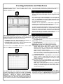
Creating Schedules and TimeZones
Schedules are customized by the use of two screens. The first is the
Schedule - Timezone screen. Click the Sched button or click
Window, Schedules to open.
is very useful in that it presents the "complete picture", displaying all
parts of the schedule, for each schedule you have to work with.
Working with Schedules
Note: Schedules are local to the lock and not shared, while
TimeZones are global and will appear in all lock configurations within
an Account.
When selecting the events and TimeZones for your schedules, you
may need to specify the User or Group ID in order to complete the
event. The Description field is used to display descriptive text for
identification purposes only. The Event Number records and monitors
ALL events stored or sent to the lock.
Schedules can be single-ended or double-ended: single-ended
schedules have a start time only; double-ended schedules have both a
start and stop time. Most schedules are double-ended.
An example of a single-ended schedule is a single "Lock" event with the
TimeZone 1 start time set to 5:00 PM only. This schedule will cause the
device to lock every day at 5:00 PM. An example of a double-ended
schedule is an "Unlock" event with the TimeZone 1 start time set to 8:00
AM and the stop time set to 5:00 PM. This schedule will cause the
device to unlock every day at 8:00 AM and lock at 5:00 PM.
Use the Schedule - Timezone screen to create schedules. Just as
each schedule consists of two main parts: the action the lock will
perform (an event) and a time the event will occur (a TimeZone), the
Schedule - Timezone screen contains two main sections:
• A TimeZone section (top) - Allows the creation of TimeZones, i.e.
the time(s) the events in the schedule will take place
• A Schedule Entry section (bottom) - Allows the selection of events
the lock will perform and links events to TimeZones.
The second screen is the Schedule View screen. Click the SchV
button or click Window, Schedule View to open.
Event Types
Unlock – Device unlocks at programmed time.
Lock – Device locks at programmed time.
Disable Group – All Users within specified Group become disabled at
the programmed time.
Enable Group - All Users within specified Group become enabled at
the programmed time.
Disable User –Specified User is disabled at programmed time.
Enable Group - Specified User is enabled at programmed time.
Passage Mode by Group 1- Open Window – Places device into
Passage Mode (unlocked state) when a member of Group 1
enters their User Code. The Start Time opens the timeframe
where the Group 1 member can enter their code, the Stop Time
ends the timeframe (closes the window).
Note: If a Group 1 member has placed the device into Passage
Mode, the device will not exit Passage Mode automatically. Be
sure to lock manually or schedule a single-ended Lock event to
coincide with the End Time.
Relay Activation by Group 1 – Open Window – Sets a timeframe
where if a Group 1 member enters their User Code, a relay
activation is sent. An example application of the relay is to disarm
an alarm control panel.
Enable Group 4 by Group 1- Open Window – Sets a timeframe
where if a Group 1 member enters their User Code, all members
of Group 4 will become enabled.
Note: Group 4 will remain enabled if a Group 1 member has
entered within the specified time. Be sure to disable Group 4
manually, or schedule a single-ended Disable Group event to
coincide with the End Time.
Switching to Schedule View
The Schedule View screen separates the TimeZone(s) for each
schedule, clearly displaying ALL parts of the schedule. The Schedule
View screen also displays the schedule as it is executed by the lock
programming.
Although the previously described Schedule Timezone screen may display only limited TimeZone information, the
complete schedule may in fact consist of multiple events depending on
how the TimeZone was created. Therefore the Schedule View screen
20
The Schedule View screen can be used to verify the full details of
each schedule, allowing you to review the arrangement of the start and
stop times for each event. The Schedule View screen is also intended
to be used to view existing schedules received from installed locks.
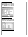
Send/Receive Information to/from the Lock
Communication Overview
There are two methods for sending data to (or receiving data
from) a lock. One method is Direct PC communication to the
lock and the other method is to use the AL-DTM-III (Data
Transfer Module).
When using a PC for communication, several options may be
used for sending and receiving data. The data transmission
may be segmented into User information, Schedules, Features
Group Status and Time/ Date or All segments may be sent at
one time. It is recommended that all data be sent at one time
as this is also how the AL-DTM-III functions.
When using the AL-DTM-III, one of three options may be
selected: "Send Program to Lock", "Receive Program From
Lock" and "Receive Log".
The following page includes instructions for the PC
communication method. Please refer to the AL-DTM III section
(see page 25) for AL-DTM-III communication instructions.
LockID
The “LockID” is a method of ensuring that the correct data is
communicated with the intended lock. Once the LockID is set,
an error message appears if information is accidentally sent or
received by the wrong lock.
Beginning with DL-Windows version 3.5.x software, what was
previously named the "Door Number" is now referenced as the
"LockID". This name change was made to accommodate a
Door Number greater than 96. As a result, utilizing Function 59
at the lock keypad is no longer supported by DL-Windows
(version 3.5.x or greater) and the new version of the software
must now be used to assign or change the LockID. With this
new system, a LockID number of 1 through 2000 is used.
When using a PC to communicate directly with the lock, the
LockID is sent to the lock when Send “All” data or Send
“Features” is selected. When “Send Program To Lock” is
selected as the AL-DTM-III function, the LockID will be sent.
(See following sections for explanations on these send
options).
First time use of DL3000 / DL2800 locks
The Master Code MUST be changed at the keypad for all
DL3000 / DL2800 locks before any other programming can
begin. Once the Master Code has been changed, Users may
be added to the lock and the PC-download function (Function
58) may be accessed. The DL3000 / DL2800 locks do not
support a PC-Download User Code (User Code 298 in all other
lock models).
Please note that the above only applies to the DL3000 /
DL2800 locks. All other lock models support the special
function User Code 298 and do not require the Master Code be
changed to access Program Mode (to access Program Mode,
please refer to the appropriate lock programming manual).
IT IS RECOMMENDED THAT THE DEFAULT MASTER CODE
BE CHANGED ON ALL LOCKS TO MAINTAIN SECURITY!
Special Function Communication User Codes
User 298
Entering the User 298 User Code eliminates the necessity of
entering a Master or Manager Code, entering Program Mode,
and inputting Function 58. Simply enter User 298’s User Code
to initiate PC communications with the lock. It is an option with
all the locks except the DL2800, DL3000 and the PL series
models.
User 299
Enter the User 299 User Code to initiate communication
between the AL-DTM-III and the lock. The User 299 code is
used only for the AL-DTM-III and will not allow passage at the
lock. This User does not require programming knowledge of
the locks or of DL-Windows; the User simply connects the ALDTM-III to the lock and enters the User 299 User Code at the
keypad.
Consult the specific lock programming manual to program User
Codes 298 and 299.
21
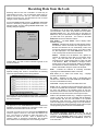
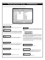
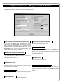
Sending Data directly to the Lock from the PC
Connect the AL-PCI2 cable's DB-9 connector to a Serial Port at
the rear of your PC (if your computer does not have an available
Serial Port, a USB adapter is available – refer to Product Communication Examples section in this manual). Connect the
other end of the AL-PCI2 cable to the lock, observing tab direction (tab to black socket). The comm port setup is covered in
the rear of this manual.
1. In DL-Windows, click the Comm button on the DL-Windows
toolbar and select Send to Lock.
6. After the selected data transfer is complete, verify that the
message "Send To Lock Successful" is displayed in the
status window of the Send to Lock dialog box.
2. The Send to Lock dialog box appears:
3. Start the communication at the lock keypad by either pressing the special function User 298 User Code at the keypad
or by entering Program Mode and accessing Function 58,
then click the Start button in DL-Windows.
"Verifying Lock Type" appears in the status window located
at the lower left corner of the Send to Lock dialog box (see
image below).
Deselecting All allows you to send any combination of available data, i.e. only User Codes and Schedules, Features,
Update Group Status, Time and Date or in any combination.
• All - Sends the complete program to the lock.
• Users - Sends all User Information including User Enable/
•
4. The Model Type, Lock Firmware Version and LockID # will
display on the screen. Verify that this information is correct.
5. If “Communicating” is not displayed after Step 3 (as shown in
the image below), then communications have failed. Check
the following:
a. COM Port Selection
b. Cable Connections
22
•
•
•
Disable status, User Codes, Group Assignments, and
Level Assignments (DL2800/ DL3000 only)
Schedule - Sends all schedules (see Schedule section for
more details)
Features - Sends all features chosen in the Features
screen (see Features section for more details)
Update Group Status - Updates the Enabled/ Disabled
status of Groups
Time/ Date - Sends the PCs current time and date.
Receiving data from the lock is equally as simple, as described
in the following section.
Receiving Data from the Lock
Receiving data from the lock is handled in a similar way as
sending data to the lock. You can selectively decide what you
want to receive from the lock (i.e. User Data, Schedules,
Features or the Event Log). Use "Receive from Lock" to review
changes to Users made at the lock.
As with the Send to Lock function, the Receive from Lock
function is selected by clicking the Comm button on the DLWindows toolbar, and then clicking Receive from Lock. The
following dialog box appears:
The differences can be User State (enabled / disabled), Prox
Card information, User Code, Group Status and Level Status
(DL2800/ DL3000 only). The screen tells you that there are
differences, and you must make the changes in DL-Windows if
you want them to be permanent. The columns in the Lock
Differences screen are defined as follows:
User Status – The User Status column displays either
Modified or Added.
Modified - Indicates that certain User data already exists in
DL-Windows, and this User data was changed at the lock.
Because DL-Windows will not automatically receive and
accept User changes made at the lock, if you wish to retain
the data displayed in the Lock Differences screen you
must manually enter this data into DL-Windows.
Uncheck All if you wish to select individual segments of the
lock to be received.
Receive User Information
If any of the Users entered at the lock keypad were found to
duplicate existing User Codes in DL-Windows, the following
screen will appear detailing those User(s) affected:
Added - Indicates that DL-Windows has updated its
software to include this User data (for "non-Admin" Users
only). This User data did not previously exist in DLWindows and no conflicts existed with any other User data
in DL-Windows. Note: All additions or changes made to
Admin Users at the lock keypad will display as "Modified",
and will NOT be added to DL-Windows. Changes made to
Admin Users MUST always be made in DL-Windows.
State – Indicates the existence of conflicting information
regarding the Enabled/ Disabled status of the User.
Prox Card (on "P" series lock models only) – Displays
proximity card information.
PC Code – Displays the User Code in DL-Windows and
indicates the conflict with the Lock Code (the Lock Code is
the User Code added at the lock).
Lock Code – Displays the User Code added at the lock.
Group 1 to 4 – Displays the Group assignment(s) of the User
at the lock compared with DL-Windows. Added indicates that
the User was added to the specified Group at the lock.
Removed indicates that the User was assigned to the Group in
DL-Windows, but was removed from the Group at the lock.
DL-Windows will not allow duplicate User Codes. Changes to
these duplicate codes should first be made in DL-Windows and
then sent to the lock.
Lock Differences
Level 1 to 4 (DL2800/ DL3000 only) – Displays Programming
Levels for the User at the lock compared with DL-Windows.
Added indicates that the User was added to the specified
Programming Level at the lock. Removed indicates that the
User was assigned to the Programming Level in DL-Windows,
but was removed from that Programming Level at the lock (see
lock programming manual for User Level definitions).
The appearance of the Lock Differences screen indicates that
disparities were found between the information stored in DLWindows and the information found in the lock.
Receive Schedules
Two types of events can occur to cause the Lock Differences
screen to appear. The first is if new Users are added to the
lock. The second is if changes to Users that exist in DLWindows are made at the lock. When a "Receive All" or
"Receive Users" is performed, DL-Windows will recognize
these "differences" and display them in the following screen:
All schedule information received from the lock will be
displayed in the Schedule View screen, and any pre-existing
schedules in the Schedule View screen will be overwritten.
See the Creating Schedules and TimeZones section for
more information.
23
Receive Event Log
When receiving the Event Log from the lock into DL-Windows,
the log can be viewed in the Event Log Viewer screen.
Note: By default only the last 50 events are received from the
lock. To receive more events, select the number of events in
the Max. Event Log Length pull-down list (as shown in the
image below). When using a PC, the complete log (up to a
maximum of 40,000 events) can be received.
Receive Update Group Status
When Update Group Status is selected in the Receive From
Lock dialog box, the Enabled/ Disabled status of the Groups is
obtained and can be viewed in the Lock Data screen. A
checkbox will appear for Groups 1 to 4, and all Groups checked
are Enabled.
24
Configure the AL-DTM
The AL-DTM may be configured for Foreign Language support
and the Door Select feature (see below). Warning: Entering the
following Configuration Mode will clear all data (lock information)
from memory.
1.
2.
Place AL-DTM into PC COMM
MODE. If not already in PC
COMM MODE, press green
button to enter this mode.
PC COMM MODE
.
.
.
on each press of the green button; when SLEEP THEN POWER
DOWN appears, press and hold the green button to exit
Configuration Mode. Note: UNCONDITIONAL FLASH ERASE
erases all lock information and configured settings in the ALDTM. To reset the AL-DTM to its factory default settings,
remove the battery, press and hold the green button for 10
seconds, then replace the battery.
.
CLOCK TEST.
Press and HOLD both the left and green buttons on the ALDTM. After several messages appear, release the buttons
when the display reads:
LCD DIS. TEST.
Entering
Config/Test Mode
(Release buttons
when displayed)
LOW BAT. TEST.
When the display reads "CONFIG. LANGUAGE", the AL-DTM
has entered Configuration Mode.
FLASH MEM. TEST.
CONFIG. LANGUAGE
Note: Pressing the green button allows you to step through
each configuration option in turn; after the last option, the list
repeats ("CONFIG. LANGUAGE" re-appears).
3.
SLEEP THEN
POWER DOWN
If you wish to configure the first option, Language, press and
hold the green button (otherwise press and release the green
button to skip to the next option shown in step 4).
EXIT TO STANDBY
UNCONDITIONAL
FLASH ERASE
LANGUAGE = ENGLISH
<BACK NEXT> EXIT
Set the language (as shown above) with the left and middle
black buttons, then press the green button to select the
language AND exit this option.
4.
The next option appears: CONFIG. FOR DTM-III MODE. For
DL-Windows 3.5x and above, this mode MUST be set to "ON".
Therefore, enter this option by pressing and holding the green
button. The following screen appears:
DTM-III MODE= ON
ON
OFF
EXIT
As shown above, the default setting is "ON". Press the green
button to both select DTM-III mode and exit this option.
5.
The next option appears: CONFIG. DOOR SELECT MODE.
Enter this option by pressing and holding the green button.
The following screen appears:
DOOR SELECT = ON
ON
OFF
EXIT
As shown above, the default setting of "ON" should be
retained if LockID numbers have not yet been programmed
and you wish to use the AL-DTM to assign a LockID number
to existing locks, or if LockID numbers are to be changed.
Otherwise set Door Select Mode to "OFF". Press the green
button to select and exit this option.
6.
Additional configuration and diagnostic options display in turn
Hold Down
to Shutdown
AL-DTM
7.
The unit may now be powered up with the new feature(s)
enabled.
Operation Mode
Once AL-DTM is configured, it is ready for use. If Door Select
Mode was set to "ON" (in step 5 above), then the AL-DTM will
power up in "OPERATION MODE", which offers two choices: SELECT
and STD:
SELECT – If Select Mode is chosen (by pressing left button), you
can choose between three modes: PC Comm Mode, Lock
Mode, and Door Select Mode:
• PC Comm Mode is used to transfer programming between
the PC and the AL-DTM.
• Lock Mode is used to transfer information between the ALDTM and the Locks. The AL-DTM will automatically
identify the LockID to which it is communicating.
• Door Select Mode is used to transfer program and assign
LockID numbers from DL-Windows.
STD ("standard") – Standard Mode will automatically put AL-DTM
in PC COMM MODE when communicating with DL-Windows
and will put the AL-DTM in LOCK MODE when performing
communications with the locks. Standard Mode should be
used for all subsequent communication after LockID has been
assigned.
Note: The AL-DTM will only allow the selection of a LockID for
which it has valid data currently programmed. Care must be taken
to that ensure the correct data is being transferred to the correct
lock.
25
Send Data from DL-Windows to the AL-DTM
Introduction
When computers cannot be transported or when electrical power is
not available, the hand-held AL-DTM device acts as a go-between-it allows the transfer of lock data from the computer (through the ALDTM) and to the lock, or in reverse (from the lock through the ALDTM back to the computer). An AL-PCI2 cable is required when
transferring from your PC to the AL-DTM. A double-ended mini
banana plug connector is used when transferring data from the ALDTM to the lock(s).
Prior to DL-Windows v3.5, Door Numbers were used to ensure
that each physical lock was correctly matched to its corresponding
data when programmed. With DL-Windows v3.5 or later, the
concept of a Door Number has been discontinued in favor of a new
system of LockID's. When communications take place between DLWindows and the lock(s), the LockID's must match in order for the
data transfer to take place. If they do not match, communications
will halt!
DL-Windows must be used to assign LockID's and this can be
performed in two ways, either:
• communicating directly with either "Send All" or "Send
Features", thus updating the locks with the new "LockID"
system
--or--
• with the AL-DTM, "Send Program to Lock" in the AL-DTM's
Door Select Mode (see Configure the AL-DTM on page 25).
Door Select Mode should only be used when it is necessary to
assign a LockID (usually first time programming of lock only).
Thereafter, ANY AL-DTM communications should be performed in
the "Lock Mode" of the AL-DTM. This will ensure that the
information is being communicated correctly between DL-Windows
and the Lock(s).
The AL-DTM displays the word "Door" and not "LockID" when
referring to door numbers (in the AL- DTM, both words are
equivalent).
Be sure to make note of the EXISTING User 299 User Code. You
will need this code(s) later when transferring data from the AL-DTM
to the lock(s). (See page 8 for a definition of User 299)
Send Program to Lock
1. Plug the AL-PCI2 cable into the correct COM port in your PC
and plug the 2-pin banana plug connector into the AL-DTM,
observing correct tab direction.
2. Open an Account in DL-Windows, and double-click on any lock
inside the selected Account. For each physical lock to be
programmed there must also be a corresponding lock in DLWindows.
3. Click the DTM button and the DTM Support screen opens. In
this screen, desired tasks must first be pre-programmed in the
DTM Function column. Therefore, for each lock that is to
receive program data, click in the DTM Function column for the
selected lock, click this arrow and the pull-down menu will
display. Select the "Send Program to Lock" function.
26
DTM Function - Right-click within in the DTM Function column.
To send program to ALL locks available, right-click in the DTM
Function column and click Change All to "Send Program to
Lock".
Click here
The AL-DTM also gives you the option of setting the date and
time of the lock (using the PC time). In the DTM Options box
at the bottom of the screen, the "Set Lock Clock" is selected
by default.
4. Transfer the Data Configuration to the AL-DTM. With the
AL-PCI2 cable correctly connected to the AL-DTM, click
Program DTM for Selected Locks (in the DTM 3 Support
screen). The following window will display:
Press the green button on the AL-DTM to enter 'PC COMM
MODE'. During data transfer to the AL-DTM, the following will
display in the AL-DTM readout screen:
PC COMMUNICATION
IN PROGRESS.
Following a successful data transfer to the AL-DTM, the ALDTM will emit several beeps (beeps are dependent on
configuration Data) and display a "Comm. Complete."
message followed by a display of current memory block status.
Beep Beep Beep
Beep
COMM. COMPLETE,
07/24/05
08:08PM
0993
MEMORY
FREE
BLOCKS
The AL-DTM, now filled with data, is ready to transfer the data
to the selected locks. The following messages will scroll back
and forth on the AL-DTM.
DTM-III: Plug in
then enter code
Waiting for lock
04/25/06 02:30PM
Send Data from the AL-DTM to the Lock
Transferring Data from AL-DTM to Locks for the first time
1. Connect the AL-DTM to the Lock. Connect the double-ended
banana plug into the AL-DTM and into the lock that is to be
programmed (observing proper tab direction).
2. The AL-DTM will display the LOCK MODE screen, press the
green button to toggle through the following screens:
PC COMM MODE
11/28/06 02:23PM
LOCK MODE
YES
NO
DOOR SELECT MODE
YES
NO
3. Toggle screens to display DOOR SELECT MODE, then select YES
by pressing the left AL-DTM button.
4. The screen displays “Set Door TO=0001”. The number "0001"
refers to the lock assigned LockID # 1 in DL-Windows. If this is
the first lock to be programmed, press the green button (SET).
(To choose a different lock, the left AL-DTM button will toggle
back through the list of locks and the middle button will toggle
forward).
5. The screen displays “Ready, Door=xxxx” (xxxx = LockID).
Press left button (GO) and the screen will then switch between:
DTM-III: Plug in
then enter code
Waiting for lock
04/25/06 02:30PM
6. Enter the User 299 User Code at the lock keypad. The ALDTM briefly displays a message that it is "Analyzing Lock –
Please Standby" and then displays the following:
as they were set up in DL-Windows as well as ensuring the
correct data transfer for all subsequent communication
attempts.
DL2800/ DL3000 Only
If the lock's Master Code and the DL-Windows Master Code do
not match, then the following AL-DTM screen will display:
DOOR 03,
SENDING
PGM PACKET
000
MASTER CODE
MISMATCH!
In this case, the solution is to either use the lock keypad to reprogram the Master Code--or--re-configure the AL-DTM (using
DL-Windows) so that both Master Codes match.
Transferring Data from AL-DTM to Locks (Changes)
After the initial programming of the locks with the AL-DTM, Door
Select Mode is no longer required. AL-DTM should now be used
in Standard Mode (Lock Mode).
All changes can be
communicated to and from the locks in this mode.
Re-enter 299
Code to Continue
7. Do not press any more buttons, and the AL-DTM will display the
following:
Door 0001,
PGM Packet
Send
001
Packet Numbers will go up until all packets have been transferred to the
lock. PDL3000 locks will take longer due a larger number of packets
(typically 5 times longer than DL3000 or DL3500 locks.
The Lock will continue to beep while in communication with the
AL-DTM. After programming is complete, the following will
display:
LOCK’S TIME AND
DATE UPDATED.
COMM. COMPLETE,
07/24/01
02:08PM
(Current date and Time)
0993
MEMORY
(Current Memory Status)
FREE
BLOCKS
8. Program Additional Locks. Repeat Steps for each lock to be
programmed. Make sure that each Lock is being assigned the
correct LockID. This will ensure that the locks are programmed
27
Receive Event Logs with the AL-DTM
After all lock programming has been completed, the AL-DTM can
be easily re-configured to retrieve event logs.
Door 0001,
LOG Packet
1. In DTM Support screen click in the DTM Function column for
the selected lock, click the down arrow and the pull-down menu
will display. Select the "Receive Log" Function.
Lock’s time and
date, updated.
Multiple locks can be programmed to receive logs by right clicking in the DTM Function column and select "Change All to
'Receive Log."
Read
001
Comm. Complete,
07/24/06 02:08PM
0993
MEMORY
FREE
BLOCKS
7. Retrieve Additional Lock Logs by repeating Steps 4 through
6 for each lock Log to be retrieved.
8. Reconnect the AL-DTM to the DL-Windows PC (using the
AL-PCI2 cable) to retrieve the Event Logs from the ALDTM. On the DTM Support screen, click Receive Data From
the DTM for Selected Locks to receive the Event Logs stored
in the AL-DTM.
2. Transfer the Configuration to the AL-DTM. Connect AL-DTM
to the DL-Windows PC (using the AL-PCI2 cable) then click
Program DTM for Selected Locks to transfer the new
configuration to the AL-DTM.
The AL-DTM status
communications.
window
indicates
successful
9. View Logs Received From the AL-DTM. Open the Event
Log Viewer screen for each lock Log.
The following window will display:
3. Enter PC Comm mode. On the AL-DTM, press the green
button and the following will display on the AL-DTM:
PC COMMUNICATION
IN PROGRESS.
COMM. COMPLETE,
07/24/06
0993
MEMORY
Typical Event Log
FREE
BLOCKS
Receiving Program with the AL-DTM
Unplug the AL-DTM.
The AL-DTM is now ready to retrieve event logs from the locks.
4. Connect the configured AL-DTM to the Lock using the double-ended banana plug cable, observing tab direction.
5. Enter the User 299 User Code at the lock keypad. The ALDTM will briefly display a message that it is "Analyzing Lock"
and then will display the following:
Re-enter 299
Code to Continue
6. Re-Enter User 299 User Code at the lock keypad.
The AL-DTM will display the following:
28
The AL-DTM can be programmed to receive the program from the
locks. Receiving the program can be a useful tool to monitor additions or changes made at the lock as well as import locks into a
new DL-Windows account.
The procedure for receiving the program from the lock with the ALDTM is similar to receiving logs. Click in the DTM Function column for the selected lock, click the down arrow and select the
"Receive Program" Function in the pull-down menu. Follow the
same procedures in the section above to program the AL-DTM
and retrieve data from the lock.
Refer to Receiving Data from the Lock on page 23 for more information.
"Global Users" Screen - Field and Button Definitions
One building may contain many locks. To add the same User to each lock again and again can quickly become tedious. The
solution is the Global Users screen. The Global Users screen allows you to enter a User's name and information ONCE, then
quickly and easily add this User to any lock (up to 2000) in the Account, as well as designate the User's specific Location Number
(within each lock) and User Code (Pin Number). In short, the Global Users screen allows you to control the status of all Users
inside an Account (usually a single building) as well as their individual Programming Levels for each lock located in the Account.
Press the Global button to Access the Global Users screen.
Sort
Use pull-down menu to
select various methods of
sorting User Names. The
default selection is the
"Classic Sort" method (by
Global ID). Other methods include sorting alphabetically, by the Custom
Field, and by the first and
last names.
User Name
Names appear in this
column when First
Name and Last
Name fields in this
screen are populated.
Field turns yellow
when both a User
Code and Prox information is required.
See page 18.
Pin Number
Each User can have the same Pin Number
(User Code) for all locks in an Account. It is
listed here for ease of viewing. Administrators can hide this column by pressing the
Hide Pins button. This column is hidden
for all other users (non-Administrators).
When hidden, this column is hidden in this
screen and also in the Lock Data screen.
Personal
Information
This basic data
helps to customize
and ensure correct
identity. Includes
Custom Field,
described below
Locks Listed by LockID
These boxes labeled 1-2000 each represent individual locks in the Account. User
status is presented in one of 4 colors:
Gray--Not assigned (no lock exists).
White--User not yet added to lock programming.
Green--User added to lock programming
and enabled.
Red--User exists inside lock programming, but is disabled.
("Global") ID
A Global ID is Account specific--it
remains constant within Accounts
only. A Global ID is not related to
User Numbers nor Programming
Levels, but acts as an internal
designation within the program
only. Note: The Global ID can be
hidden from view. See note below.
ProxCard Data
Use the AL-PRE to enroll ProxCards® and ProxKey® keyfobs,
and these fields will automatically
populate. Press Add Card to
open the ProxCard Enrolling
dialog. See page 17 for procedures.
Press Remove Card to remove
all Prox information from all locks.
Click in this column to highlight User and view personal
and Account information. In
this example, Dave Phillips is
highlighted, displaying his User
data in the window.
Set Group Assignment
Opens a new window, allowing the
assignment of the User to a specific Group within a lock. Also
allows a single user to be assigned
to different Groups in different
locks within an Account.
Pin No.
Same as a User Code.
Custom Field
Allows a customized field of up
to 15 characters. This field is
set in the Options screen and
once changed remains identical
for all locks in all Accounts.
Comments
Allows text up to 256 characters.
Add Administrative Users
Allows manual assignment of
Users to User Numbers, allowing
Users to be assigned to specific
Programming Levels within a
lock. The range of programming tasks allowed by these
Programming Levels are outlined in each lock's programming
instructions.
Battery Icon
The battery icon indicates
the charge status of the
battery inside the AL-PRE.
Prox Enroll Status
This light indicates the status
of the AL-PRE after enrolling
a ProxCard®.
(Green = OK, Red = Fail)
Search Utility
As User Names start to fill up,
this utility saves time.
Search by Name allows a
search by either first or last
name;
Search by ProxCard® for
Prox Number search.
Search by Pin allows a
search by User Code (Pin).
Type name here
Enter search criteria
(either first or last
name, Prox Number
or Pin Number)
Reset Name Search
Press to start a new
search. Press this
button and you lose
the results of your
previous search.
Hide Pins
Allows PIN numbers to be hidden for increased security.
NOTE:
The Global ID is a means of determining how many Users are listed within an Account. This
"Global ID number" is used by the program only and has no relationship to where the User is
located within a particular lock. The Global ID is not a User Number, and does not determine
Programming Levels within locks.
Delete User
Press to delete User from
all locks in the Account,
removing all information
from the system (not just
disabling).
Close
Press to close window.
Set Level Assignment
Opens a new window, allowing
the assignment of the User to a
specific Level within a lock. Also
allows a single user to be assigned to different Levels in different locks within an Account.
Note: Applies to DL3000 and
DL2800 locks only.
Level Assignments are predefined User Types (such as Master, Installer, Manager, Supervisor, and Print Only User). Each
possess a specific range of programming tasks they are allowed
to perform.
29
"Set Administrative Users" Screen - Field Definitions
The Set Administrative Users screen is used assign Users to the administrative locations within the locks, determining their
Programming Levels and therefore defining the range of programming tasks a User is allowed to perform. Press the Add
Administrative Users button (on the Global Users screen) to Access the Set Administrative Users screen.
User Name
Names appear in this column when
First Name and Last Name fields
in this screen are populated. This
field turns yellow when both a User
Code and Prox information is required. See page 18 for details.
Click a row in this column to highlight
User and view personal and Account
information. In this example, the Master
Code is highlighted, displaying the default
User information in the window, with the
fields ready to be populated.
Pin Number
Each User can have the same Pin Number
(User Code) for all locks in an Account. It is
listed here for ease of viewing. Administrators can hide this column by pressing the
Hide Pins button. This column is hidden
for all other users (non-Administrators).
When hidden, this column is hidden in this
screen and also in the Lock Data screen.
Custom Field
Allows a customized field of up
to 15 characters. This field is
set in the Options screen and
once changed remains identical
for all locks in all Accounts.
Administrative Users are special in
that they can perform programming
tasks that non-Administrative ("Basic")
Users cannot perform (such as changing or adding new User Codes, etc.).
Some of these Administrative Users are
allowed more tasks than others, and the
distinction between Users and their
allowed tasks is known as a
"Programming Level". (See the definition of "Programming Level" on page 7).
Pin No.
Same as a User Code. Enter
changes in this field.
Comments
Allows text up to 256 characters.
ProxCard Data
Use the AL-PRE to enroll
ProxCards® and ProxKey®
keyfobs, and these fields
will automatically populate.
Press Add Cards to open
the ProxCard Enrolling
dialog. See page 17 for
procedures.
Set Group Assignment
Opens a new window, allowing the
assignment of the User to a specific
Group within a lock. Also allows a
single user to be assigned to different Groups in different locks within
an Account.
Press Remove Card to
remove all Prox information
from all locks.
Delete User
Press to delete User from
all locks in the Account,
removing all information
from the system (not just
"disabling").
30
Personal Information
This basic data helps to
customize and ensure
correct identity. Includes
Custom Field, described
below.
Press Accept to save the
information added, and
press Cancel to discard all
entered information.
"Lock Data" Screen - Field Definitions
The Lock Data screen is used to view User Codes, Group Associations and Program Levels inside individual locks.
9Quick Tip:
After entering Users and assigning Users to Location
Numbers ("Slots") by using the Global Users screen (see
page 29), use the Lock Data screen (shown at right) to view
and confirm the User Location assignments made inside
each individual lock.
User Locations determine
Programming Levels for each lock.
Remember, Inside each lock:
User Number = User Location = Location Number = Slot
Name
GP1 GP2 GP3 GP4
In this field, the First and Last Name entered in the Global Users screen is
displayed. The Name will appear on any activity reports generated, such as
in the Event Log Viewer screen. The default labels (such as "Supervisor
1") that appear in the Name column when a new lock is created are for
reference only. As Users are assigned to each User Number "slots", the
Name will appear in place of the default values shown.
User No.
This is the User Number inside the lock that determines the
Programming Level of each User (see "Terminology" on page 7). Note:
The PDL series locks can contain up to 2000 Users, and 300 Users for
the DL3000/DL3500.
User Code
Also called User Access Codes or PIN No. Codes, User Codes are
numbers the User enters into the lock keypad to unlock the lock or device.
User Codes are entered via the Global Users screen. Administrators can
hide this column by pressing the Hide Pins button. This column is hidden for
all other users (non-Administrators).
Card ID
This field is used to physically identify a ProxCard that has been
assigned to a User. The number printed on the ProxCard (up to 9
digits) may be typed into this column. This is for reference only.
Facility
®
®
The Facility Code is a site code on all ProxCards and ProxKey
keyfobs, and is usually the same for all ProxCards® (but not printed on
the card or fob). Usually, the site administrator can provide Facility
Code information.
Card Type
The Card Type specifies the format of the card being used (i.e. HID 37
bit format, etc. See pages 18-19). The Card Type is not printed on the
card or fob itself, and usually the site administrator can provide this
information.
(User Group Association)
Each User can be associated with up to 4 Groups. Groups of Users can be
enabled or disabled simultaneously. This User/Group association is typically based
on the User’s department, or the shift to which the User is assigned. If any User
attempts to access the lock outside of the Group's scheduled hours, the lock will
deny entry.
Enable
Indicates the current status of the User. If the User is currently enabled,
a 9 will appear under the Enable column.
Type User Name to Search
Type in User name to be searched.
For example, enter “Bob”. All names with “Bob” in the User Name will
display.
Send/Receive
If clicked, the Send/Receive button will provide a shortcut to the
Receive from Lock or the Send to Lock communication dialogs.
Group Enable
For DL3500 and PDL Series Locks only. Users that have been
assigned a Group number can be enabled/disabled by checking or unchecking the associated box. NOTE: Group Enable data is not
transferred by the AL-DTM.
Print
Click to send to your default printer all data inside all columns and rows
listed in the Lock Data screen.
Close
Click to close Lock Data screen.
Card Code
The Card Code is usually laser-printed on the card or fob itself. If not
printed on the card, see the site administrator for this information.
31
"Event Log Viewer" Screen - Field Definitions
The Event Log Viewer screen is used to view each event (also called the "Audit Trail").
Note: In the Event Log Viewer screen, each column heading (Date, Time, etc.) can be clicked to sort its data.
Date
The date the event occurred (MM/DD/YY). Click the heading to sort its
contents.
Time
Export Log
Click the Export Log button and two selections appear (as shown
below): You can click either Export Log to Text File or Export Log to
CSV File.
The time the event occurred in 24-hour military time. Logs retrieved
from the DL3000 with the AL-DTM have an accuracy of one minute, for
all other locks accuracy is one second. Logs retrieved with a computer
have an accuracy of one second. Click the heading to sort its contents.
User No.
This is the User Number inside the lock that determines the
Programming Level of each User (see "Terminology" on page 7).
If you click Export Log to Text File, the log will be saved in the form of
a .txt (text) file, and a popup will appear detailing the name and path of
the file. Note: If the text file is viewed using Courier font typeface in
Notepad, all columns in the file will align.
If you click Export Log to CSV File, the log will be saved in the form of
a CSV (Comma Separated Value or comma delimited) file, and a popup
will appear detailing the name and path of the file. Note: This CSV file
can be viewed in MS Excel, and each column in the Log will be aligned
in Excel under its own column heading.
Name
Most often, this is the name that is entered in the Name field on the
Global User screen. If a name has been entered for the User that is
associated with the event, the name of the User will be displayed.
Max. Event Log Length
Enter the Maximum length of the Event Log list.
Event
This is a description of the logged event that occurred. Click the
heading to sort its contents.
Default View
Clears the Event Log Filter and displays all Event Log Events.
32
Print
Click to send to your default printer the displayed data inside columns
and rows listed in the Event Log Viewer screen. Only those records
displayed (specified in the Maximum Event Log Length) will be
printed.
Close
Click to close the Event Log Viewer screen.
"Programmable Features" Screen - Options tab
The Programmable Features screen is used to program lock options and a variety of programmable Features.
Note: Daylight Saving Time features apply to v3.6.0 only. For version 3.5.6, see page 53.
Group 2 Enables and 3 Disables Passage Mode
A Group 2 User will put door into passage mode (lock is unlocked). A
Group 3 User will take door out of passage. Caution! The consequences
of accidentally selecting this option can cause a security breach! (Not
applicable to the DL2800/DL3000).
One Time Only for Group 3 Users
If checked, allows Group 3 Users to unlock the door one time only, then
their User Code or proximity card becomes disabled. (Not applicable to
the DL2800/DL3000).
The above screen is from a PDL3000 lock. Note the Daylight Saving Time area includes the 24
pre-programmed modes as well as a 25th mode to allow customization (selecting mode 25 from
the pull-down list activates the Custom DST button). This screen layout is typical for most locks.
For other locks, see the Daylight Saving Time description below.
LockID
Door Number must be between 1– 2000*.
If the lock is a new lock without a designated LockID, the ID number
specified in this field will be assigned to the programmed lock. If used
with the AL-DTM Data Transfer Module, this is the LockID number the
AL-DTM will use to identify itself to the lock, insuring that the proper
data inside the AL-DTM will be matched to the correct lock.
*Varies with lock model.
Pass Time In Seconds
The duration in seconds that the lock will remain unlocked after a valid
code has been entered (valid entries are 3, 10 & 15 seconds).
Entry Delay in Seconds
Delays door entry after valid User code is entered. Note: For DL3500
and PDL3000, valid entries are 0, 5, 15 & 45 seconds.
Lockout # of Attempts 1-9
The maximum number of invalid entry attempts (with wrong User Code)
the lock will allow before it goes into lockout mode (where it will refuse
to recognize ANY User Code entry). The lock will shut down for the
period programmed in the Lockout Time in Seconds field which
follows. Valid Attempt entries are 1-9.
Star Key as Enter Key
If checked, all codes entered must be followed by the
a
key.
Disable Sounder
Disable Lock Sounder to enable silent operation. (Not available on all
locks)
Enable Star Key as Doorbell
Check to allow the a key to act as a doorbell. Sounder must be
enabled for doorbell operation. (Not available on all locks)
Enable Entry Sounder
Check to enable sounder to activate upon each Access Granted or
Remote Input activation. (Not available on all locks)
Daylight Saving Time (v3.6.0 only)
The lock will adjust for Daylight Saving Time. Daylight Saving Time
configuration settings for the PDL3000 lock are shown above (most
other locks similar) allowing 23 pre-set modes for the varied DST
adjustments throughout the world. For this lock, select mode "1" for no
DST adjustment and select mode "25" and click the Custom DST
button for custom settings. Note: The configuration settings for the
DL3000, DL2800 and DL/PDL1300 locks will appear differently, as
detailed on the next page. In addition, for a list of locks and firmware
versions that support this new Daylight Saving Time feature, and for
information regarding custom settings and other details, see the next
page.
Lockout Time in Seconds
The duration of time the lock refuses to recognize ANY User Codes
after the maximum number of invalid entry attempts (with wrong User
Code) has been reached (valid entries are 1-60 seconds).
Group 2 Toggles Passage Mode
Door Ajar
For use with the DL/PDL3300 lock. Check Enable Door Ajar
Monitoring to enable this feature. Check Door Ajar Trip Time (delay
time in seconds after the door first becomes slightly open) from the
drop-down list, and check Use Sounder on Door Ajar to enable an
audible warning upon a valid door ajar trip.
A Group 2 User will toggle passage mode (lock is unlocked). Caution!
The consequences of accidentally selecting this option can cause
a security breach! (Not applicable to the DL2800/DL3000).
33
"Programmable Features" Screen - Customize DST
Daylight Saving Time features below apply to v3.6.0 only.
The Programmable Features screen, Options tab will vary depending the lock model, as shown below. Some locks require either DST be disabled
or customized, other locks also allow the selection of pre-set DST modes for the varied DST adjustments throughout the world. See below for details
regarding the Custom DST button and customizing the DST start and end dates. In addition, see below for a list of Locks and firmware versions that
support the new Daylight Saving Time feature.
⇒ For version 3.5.6, see page 53. Set Daylight Saving Time configuration settings as follows:
Daylight Saving Time area for DL3000 /DL2800:
If Daylight Saving Time is elected to be used,
check the box to activate the Custom DST button.
Uncheck the box to disable DST.
Daylight Saving Time area for DL/PDL1300
locks: If Daylight Saving Time is elected to be
used, select mode 2 - Custom Daylight Saving
Time from the pull-down list to activate the Custom DST button. Select mode "1" to disable DST.
In any of the screens above, click the Custom DST button and
the following dialog appears:
Daylight Saving Time area (for locks other than
the DL3000/DL2800 and DL/PDL1300): If Daylight
Saving Time is elected to be used, select mode 25 Custom Daylight Saving Time from the pull-down
list to activate the Custom DST button. The pulldown menu also allows 23 pre-set modes for the
varied DST adjustments throughout the world. Select mode "1" to disable DST.
Repeat to select the End Month/Day.
Daylight Saving Time customization is only supported with the
locks listed in the chart located at the bottom of this page.
All DST adjustments will take place at 2:00 AM the days selected.
Click OK to save and click Cancel to discard changes.
The default Start and End dates are set to the new DST laws enacted for 2007 in the USA:
• Start Date: Second Sunday in March
• End Date: First Sunday in November
To customize these dates, click the pull-down menu and a calendar will appear:
Click to scroll through
the months
Click any day in
the selected
month to set
Current date is shown and
is circled when current
month is displayed
You can also click within the pull-down list to highlight the numbers and type in the digits manually:
Click in the pull-down list field to
type the digits manually
34
Click the pull-down menu and a calendar will appear.
Locks and firmware versions that support the new
Daylight Saving Time feature:
• DL1300 v38d
• PDL3000 v40b
• PDL1300 v39e
• DL3500 v14i
• DL2800 v35g
• PDL3500 v41a
• DL3000 v34k
"Programmable Features" Screen - Relay Functions tab
The Features screen is used to program Relay Functions and other programmable Features. If programmed, one or more of the following relay
Functions will activate an external Relay for an interval of 3 seconds, if the condition is met. If Relay follows Lock/Unlock Status is selected, the
relay will remain activated as long as the door is unlocked.
Select any of the Functions below to Activate the Relay Output (more than one may be selected).
Remote Input While Enabled
Will activate relay when the Remote Release is activated. This will
provide an alert that access has been granted via the Remote Release.
Remote Input While Disabled
Will activate relay when the Remote Release is attempted to be
activated but is disabled. This will provide an alert that an unsuccessful
access has been attempted via the Remote Release.
Locked by Schedule
Will activate relay if the lock has be locked by a programmed schedule.
Unlocked by Schedule
Will activate relay if the lock has been unlocked by a programmed
schedule.
Lockout # of Attempts Exceeded
Failed Entry Attempt
Will activate relay if any unsuccessful Use Code entry occurs. This will
provide an alert that an unauthorized Use Code entry has been detected.
Disabled User Entered Code
Will activate relay if a User enters their User Code while that User Code
is disabled. Provides an alert that a disabled Use Code entry has been
detected.
Authorized Entry
Will activate relay if the number of User Code entry attempts has been
exceeded and the keypad is locked out.
Ambush Function Activated
Will activate relay if the Ambush Code is entered followed by a valid
User Code.
Any Keypress of Card Entry
Will activate relay any time a key is pressed or a proximity card is
presented
Will activate relay anytime a User enters a valid User Code and is
granted access.
Relay follows Lock/Unlock Status
Scheduled (Group 1 Activated)
Will activate relay if the lock has been programmed for Scheduled Relay
Activation (Group 1 Initiated) and a member of Group 1 has entered
their User Code within the required window.
Relay will activate when lock is unlocked. Relay power must be
provided from an external power supply. If Relay follows Lock/Unlock
Status is selected, the relay will remain activated as long as the door is
unlocked. This feature supersedes all other relay options.
Activate Relay on Door Ajar
For use with the DL/PDL3300 lock. Relay will activate when Door is
found to be ajar, that is, left open after a specified period of time (see
the Options tab on previous page). If Activate Relay On Door Ajar is
selected, the relay will remain activated for as long as a valid door ajar
trip is in effect.
35
"Programmable Features" Screen - Remote tab
This screen is used to program Remote Input Functions. Note: Remote Disabled Lock, Forced Lock Follows Remote or Forced Unlock
Follows Remote should only be used with external power to the lock.
Select one of the Remote Input Functions below.
Remote Release (Momentary)
Remote input is enabled and will cause the door to momentarily unlock.
Remote Toggles Passage Mode
If enabled, the remote input will toggle Passage Mode. Passage Mode
allows passage through the door without the need for a User Code.
Remote Disables Lock
Remote input disables the lock while a short is maintained across
remote input. Therefore, if a switch is used for the remote input, as long
as the switch is closed the lock will be disabled and its state cannot be
changed. As long as the switch is open, the lock will be enabled.
36
Forced Lock Follows Remote
Checking this box will cause the lock to lock when a short is maintained
across the remote input. The lock will remain locked until the next User
Code entry, at which time the lock will return to Passage Mode.
Forced Unlock Follows Remote
Checking this box will cause the lock to unlock when a short is
maintained across the remote input. The lock will remain unlocked until
the next User Code entry, at which time the lock will lock.
Remote Puts Lock in PC Comm Mode
For use with DL-WINDOWS software. The remote input will act as User
298 or keypad Function 58. See page 8 for details regarding keypad
Function 58.
"Programmable Features" Screen - 4000 Series tab
These screens are used to program the Residency/Privacy options and features for the 4000 Series locks. The screens below display the DLWindows screen defaults (which also reflect the "out of box" factory default programming). Shown below (left) a PDL4100 ("Privacy") lock and (right)
a PDL4500 ("Residency") lock. Note: DL locks do not provide PROX access, therefore the DL lock screens do not reference PROX options.
"Residency" Mode
(Default for 4500
Series)
"Residency" Mode
"Privacy" Mode
"Privacy" Mode
(Default for 4100 series)
4100 Series Locks
4500 Series Locks
PDL4100/DL4100 & PDL4500/DL4500
Privacy and Residency Features
The 4100 series locks leave the factory as "Privacy" locks, with the below "Privacy Mode" as the default program. If you wish, 4100 series locks
can be re-programmed as "Residency" locks (see below, "Residency Mode"). The following provides basic descriptions of the two modes. For
more information, see WI1194 and/or WI1195.
The 4500 series locks leave the factory as "Residency" locks, with the below "Residency Mode" as the default program. If you wish, 4500 series
locks can be re-programmed as "Privacy" locks (see below, "Privacy Mode"). The following provides basic descriptions of the two modes. For
more information, see WI1194 and/or WI1195.
Note: Only PDL series locks provide PROX access. Although the below descriptions apply to PDL series locks, these descriptions can also
apply to DL series locks, however all references to PROX features should be ignored. In addition, the 4100 series locks have a button on the
exterior/outside of the locks, and the 4500 series locks have a deadbolt knob.
Privacy Mode (Factory Default for 4100 Series Locks):
"Privacy Mode" is designed to allow access to individuals with access codes (or PROX cards) and is typically used for rooms needing privacy
from others such as bathrooms, dorms and meeting rooms.
"Privacy Mode" initially provides a normally locked state. To enter, the user must use a User Code, key, or present a PROX card. Once inside, the user presses the button (on 4100 series) or throws a deadbolt (on 4500 series) that disables the keypad (and PROX card reader),
disallowing others to enter for a fixed amount of time ("Privacy Duration"). The red LED on the exterior/outside of the lock will blink-indicating the room is occupied. When the initial user exits, the 4100 series lock reverts back to its originally locked mode, again allowing
access to any authorized users.
The Privacy Duration for the 4100 series lock can be programmed to disable User Code and PROX card access for up to 250 minutes.
When active, all User Numbers 12 and higher are disabled, and User Numbers 1 - 11 (or a key) can always override this lockout feature by
entering their User Codes and/or PROX cards. Programming: As shown in the images above, check "Disable Keypad/Prox on Button
Press (or Deadbolt)" and select a Privacy Duration (default is 10 minutes, valid entries 001-250).
Residency Mode (Factory Default for 4500 Series Locks):
The "Residency Feature" is provided to prevent a person from unintentionally having the door lock behind them when stepping outside
briefly. Typically used in retirement homes and college dormitories.
"Residency Mode" initially provides a normally locked state. To enter, the user must use a User Code, key, or present a PROX card. The
4100 series lock will then re-lock when door is closed. However, turning the handle and exiting from the inside will unlock the 4100 series
lock and set it to an unlocked state.
Any of the following will restore the lock to its normally locked state: (1) the user returns, enters, and presses the button (or throws the deadbolt) from the inside; (2) someone already inside the premises presses the button (or throws the deadbolt); (3) pre-programmed scheduling;
(4) entering a valid User Code, presenting a valid PROX card, or locking with a key. Programming: As shown in the images above, check
"Cancel Passage on Button Press (or Deadbolt)", and "Leave Unlocked on Exit (Passage)".
37
"Schedule-TimeZone" Screen - TimeZones Area
This screen consists of two parts--the TimeZones area (top) and the Schedule Entry area (bottom). The TimeZones area is used to program the
time the event(s) will occur, and the Schedule Entry area is used to create events that can be linked to the times created in the TimeZones area.
This page will focus on the TimeZones area. See next page for the Schedule Entry area.
9Quick Tip:
Days of the Week
RIGHT click on the
Enable Column, select
which day(s) to enable
from the following:
LEFT click to select
desired day(s).
TimeZone
Select TimeZone: Use the Selector to select the desired Time Zone.
250 maximum allowed.
Add
Add TimeZone. Click the Add Button, the Select Time Zone drop-down
(described above) will show the additional Time Zone selection option.
If the only Time Zone available was TimeZone 1, you will now see an
option for TimeZone 2. 250 maximum allowed.
Delete
Delete TimeZone: If it becomes necessary to remove a TimeZone, first
select the TimeZone by clicking on it in the Select Time Zone window.
When selected, remove the TimeZone by clicking Delete.
Day
The Day column cannot be altered. Select the day by clicking the day
desired under the Enable column.
Start
This is the time that the TimeZone will begin for the day selected. To
select a Start time, click the mouse cursor in the Start cell for the
desired day. Highlight the entire cell to completely re-type start time, or
just highlight the section to be altered and then type in the new value.
Stop
This is the time that the Time Zone will stop for the day selected. To
select a Stop Time, click the mouse in the Start cell for the desired Day
of the week. Highlight the entire cell to completely re-enter start time, or
just highlight the section to be altered and then type in the new value.
9Quick Tip: Copy Start Times
38
Note:
Open-ended TimeZones can be
entered by creating (or modifying) a
TimeZone and leaving the stop time
blank. This would also suppress
any other events for that TimeZone.
For example, your regular schedule
is Mon-Fri 8-5 but one of those days
is a holiday. Another TimeZone
could be created with the end time
removed for the holiday.
That
TimeZone would be used in
conjunction with a LOCK event and
that door would stay locked for that
TimeZone duration.
9Quick Tip: Copy Stop Times
Highlight the Stop Time that is to be copied to all other Stop Times,
then click the RIGHT mouse button, the following will appear:
LEFT click to select.
All Stop Times should now be set to the copied Stop Time.
Month
All, January - December
TimeZones can be set for all 12 months of the year (Default=All), or for
specific months. To select, click mouse in Month cell, from the dropdown menu select the desired month.
Day of Month
All, 1-31
TimeZones can be set for specific days of the month (Default=All). To
select, click mouse in Day of Month cell, and from the drop-down list
select the desired day.
• If a specific month AND day is selected, then the TimeZone will be
set to occur on only this specific day in the month chosen.
• If the Month field is set to All, and a Day of Month is selected, then
the TimeZone will be set to occur only on this specific day every
month of the year.
Enable
Double-click on the day(s) desired.
appear under the Enable column.
If the day is enabled, a 9 will
Print Schedules
At any time, all programmed TimeZones can be printed by clicking on
the Print Schedules button.
Switch to Sched. View
Highlight the Start Time that is to be copied to all other Start Times,
then click the RIGHT mouse button, the following will
appear:
Combines the times programmed in the TimeZone area with the events
programmed in the Schedule Entry area of the Schedule-TimeZone
screen. Results are displayed in the Schedule View screen.
LEFT click to select. All Start times will now be set to the copied Start
Time.
NOTE: The Schedule-TimeZone screen is "Global"--when a new TimeZone is created, it can be used for all locks in an Account.
"Schedule-TimeZone" Screen - Schedule Entry Area
This screen consists of two parts--the TimeZones area (top) and the Schedule Entry area (bottom). TimeZones area is used to program the time
the event(s) will occur, and the Schedule Entry area is used to create events that can be linked to the times created in the TimeZones area. This
page will focus on the Schedule Entry area. See previous page for the TimeZones area.
Schedule
Entry Area
Event Number
An Event Number is assigned to each scheduled event. Up to 500
events can be scheduled for the DL3500 and PDL3000 locks, and 150
events for the DL3000. This number is displayed for reference only.
Description
Any text description of each scheduled event can be entered. Up to 30
characters are allowed. Displayed for reference only.
User or Group ID
This is the Group or User Number associated with the scheduled event.
If the event is associated with a Group, valid entries are 1 to 4. If the
event is associated with a User Number, valid entries are 2 to 2000 (for
the PDL3000).
Note: When adding data to the "User or Group ID", "Event" and
"TimeZone" columns, all three columns must be completed at one time.
For example, if data is selected in only two columns for one event, and
the third column is left blank, all information for the event will be
automatically deleted.
Event
These are the events which will affect the associated Groups or Users
at the time and the duration specified in the Schedule-TimeZone
screen.
The events are:
(Blank)
Unlock
Lock
Disable Group
Enable Group
Disable User
Enable User
Passage Mode by Grp1-Open Window
Relay Activation by Grp1-Open Window
Enable Group 4 by Grp1-Open Window
Note: When adding data to the "User or Group ID", "Event" and
"TimeZone" columns, all three columns must be completed at one time.
For example, if data is selected in only two columns for one event, and
the third column is left blank, all information for the event will be
automatically deleted.
TimeZone
Click in the cell and use the drop-down menu to select the TimeZone
number you wish linked to the schedule entered.
Note: When adding data to the "User or Group ID", "Event" and
"TimeZone" columns, all three columns must be completed at one time.
For example, if data is selected in only two columns for one event, and
the third column is left blank, all information for the event will be
automatically deleted.
Clear Entry
To clear all items programmed, highlight the line to be cleared (click on
the column to the left of the Event Number column), and then click
Clear Entry.
Clear All
Clears all scheduled entries.
Print Schedules
At any time, all programmed schedules can be printed by clicking on
Print Schedules.
Switch to Sched. View
Combines the times programmed in the TimeZone area with the events
programmed in the Schedule Entry area of the Schedule-TimeZone
screen. Results are displayed in the Schedule View screen.
39
"Schedule View" Screen - Program Field Definitions
The Schedule View screen combines the times created in the Schedule-TimeZone screen. The Schedule View screen displays schedules (with
their event time information) listed in separate rows. In addition, schedules received from locks are viewed only in the Schedule View screen.
Notes on the Schedule View screen
The Schedule View screen is defaulted as a read-only screen. Editing events from this screen is not recommended.
Note: If a lock with a program created through keypad programming is uploaded, it can only be viewed or altered through the Schedule View screen, not
the Schedule-TimeZone screen. Before any downloading can be performed from the Schedule View screen, select Send Schedule from Schedule
View option in the Options dialog.
Event Number
An Event Number is assigned to each scheduled event. This number is
displayed for reference only.
Day of Month
This is the Day of the Month enabled in the TimeZone area of the
Schedule-TimeZone screen.
Month
This is the Month entered in the TimeZone area of the ScheduleTimeZone screen.
Day of Week
This is the Day of the Week entered in the TimeZone area of the
Schedule-TimeZone screen.
An Unlock Schedule Entry using a Start & Stop Time Zone will create
a START Unlock and STOP Lock time in the Schedule View.
Creating Schedules is a 2 step process:
Step 1: First set the time the event will occur in the TimeZones section
of the Schedule-TimeZone screen.
Step 2: Select the scheduled events in the Schedule Entry area of the
Schedule-TimeZone screen.
TimeZones are typically based on shifts, regular business hours or
other similar requirements. These TimeZones will be used to enable/
disable Users by individual User or Groups of Users in the Schedule
Time screen. By default, DL-Windows creates a default TimeZone
which selects all 7 days of the week, from 8:00 AM to 5:00 PM.
Clear Entry
Available only if Read Only in Schedule View is disabled
To clear all items programmed, highlight the line to be cleared (click on
the column to the left of the Event Number column), and then click
Clear Entry.
Time
This is the time entered in the TimeZone area of the ScheduleTimeZone screen.
Event
This is the Event entered in the Schedule Entry area of the ScheduleTimeZone screen.
User or Group
This is the User or Group that was entered in the Schedule Entry area
of the Schedule-TimeZone screen.
40
Clear All
Available only if Read Only in Schedule View is disabled
Clears all scheduled entries.
Print
At any time, all programmed Schedules can be printed by clicking Print.
Close
Click to close the Schedule View screen.
"Options" Screen - Program Field Definitions
The Options screen allows you to select Account and DL-Windows preferences.
Send Schedule from Schedule View (supervisory)
When schedules are received from locks into DL-Windows, they can
only be viewed in the Schedule View screen. Because edits can be
made directly in the Schedule View screen (see above, "Disable
Editing in Schedule View (supervisory)", it is convenient to send
Schedule information directly from the Schedule View screen back to
the lock directly. To allow the ability to update the lock from the
Schedule View screen, check this box. To enable password, select
Options, Password Setup, Supervisor Password.
Global Users Custom Field Label Name
This editable field controls the label name of the Custom Field (located
under the Pin No. field in the Global Users Screen). Type up to 15
characters. Once this field is changed, the text of the label remains
identical for all locks in all Accounts.
Open Event Log Viewer on Receive
When checked, allows the Event Log Viewer screen to open
automatically after receiving data from a lock
Show Global User ID's
The Global User ID number can be hidden from view. A Global User ID is
used within the Global Users screen and simply lists all potential Users
within an Account. DL-Windows keeps track of each "Global User" listed in
the Global Users screen by use of the Global ID number. The number acts
as an internal designation only.
StartUp Screens
Selected screens will automatically open upon double-clicking a
selected lock in the Account Tree field.
Global Ambush Code
A 2 digit code which will activate the auxiliary relay if entered before a
valid User Code, and is the same for all locks in the Account. You must
also select Ambush from the Relay Function List. Uncheck the box to
disable the Ambush code (as shown).
Language Support
Select the Grid Colors for all Grids
Allows you to personalize the colors of grids and header background
"backcolors" and the accompanying text. Click Reset Grid to Default
Colors to change the selected colors back to their default factory
settings.
Select the language that will populate all DL-Windows screens from the
drop-down list.
Working Directory
Select the directory in which all DL-Windows files will reside.
41
Exporting and Importing Data
Exporting Data
Tools > Export Active Account to CSV
This feature exports all User data from a DL-Windows
Account and saves the data to a .CSV (comma separated
values file) file. The .CSV file can then be imported into
another Account using DL-Windows.
Click Tools, Export Active Account to CSV on the menu
toolbar to export data. For each .CSV file, each line in the file
is one entry, and the fields in each entry are separated by
commas. Exported .CSV files will be placed in the C:\DLWindows\Export folder.
When the Account has been
converted to a .CSV file, the following popup appears:
Note: Two Files will be placed in the Export directory:
• Acct3.csv - The exported file, in a comma delimited format.
• Acct3.log - The error log file. If populated, this file will
reference the line number of the error in the .CSV file.
The file size of these Accounts will typically be larger than
what a 1.44 MB floppy disc will hold. A ZIP Drive, memory
stick or network drive is advised for transferring exported files.
It may be possible to WinZip each file and place it on a floppy
disc one file at a time, but that depends on the size of the
Account.
Importing Data
The Tools > Import CSV File menu contains two import utilities
to allow you to combine Users from one Account with another
Account.
Before using either Import utility, first open the Account to which
the data will be imported. If the Account does not yet exist, a
new "test" Account can be created if desired. Next, transfer the
files to the computer where the Accounts are to be restored and
place the files in the DL-Windows Import directory (typically C:
\DL-Windows\Import).
Tools > Import CSV File > Import CSV File From DL-Windows
This feature imports a .CSV file (comma separated values
file) created by the DL-Windows Export Active Account to
CSV menu option (see "Exporting Data" above).
Note: If any Users exported are not wanted, you can open
this file in Excel and delete the unwanted entries (always
delete the entire line and not part of a line).
42
Tools > Import CSV File > Import CSV File From Excel
This menu selection allows you to import a .CSV file that was
created in MS Excel and saved as a .CSV file. To create the
Excel file, open Excel and populate each cell as follows:
Cell A1 = First Name
Cell B1 =Last name
Cell C1 = Address
Cell D1= City
Cell E1= State
Cell F1= Zip Code
Cell G1 = Telephone
Cell H1 = Variable Custom Field
To export the file from MS Excel as a comma separated values
file, click File, Save As…, then in the Save as type: pull-down
menu select CSV (MS-DOS) (*.csv). Note: Unused cells must
be left blank.
Transferring Account Files Between PC's
We recommend using a USB drive flash memory card when
transferring DL-Windows Account files from one computer to another. To ensure a successful transfer, both computers must
correctly operate with USB drive flash memory cards before performing this procedure. DL-Windows must not be running on
either system. Note: The Tools, Import a Single ADF Account File menu feature used in the procedure below is only
supported by DL-Windows versions 3.5.5 and greater.
Account files exist in pairs:
• Acctx.Adf is the Account file
• Acctx_Log.adf is the Event Log for the Account file
Remove the USB drive from the source computer and connect it
to the target computer. Similar to the previous steps, at the target computer, open Windows Explorer and locate the USB
drive. Highlight the Account files to transfer, right-click and select Copy. Locate and click to highlight the DL-Windows folder.
Right-click in the right hand pane and click Paste.
Launch DL-Windows. Click Tools, Import a Single ADF Account File (see the image below). Note: The word "Single" in
the menu refers to both Account files that were copied.
In the example that follows, the names Acct2.adf and
Acct2_Log.adf are used. Note that some Windows systems are
not configured to display file extensions (you may only see Acct2
and Acct2_Log -- this is OK. Please proceed as if the file extensions are displayed.
At the source computer (from which you want to transfer the DLWindows Accounts), open Windows Explorer from the Start,
Programs menu. Locate the DL-Windows installation folder (if
you selected the default folders, look in "C:\DL-Windows").
Highlight the Account files you wish to transfer (hold down the
"Ctrl" key and click on each file). Right-click the highlighted files
and click Copy (see image below).
Click Yes to the import question and an Open file dialog box appears:
Locate your USB drive in the left hand pane of the Windows Explorer window. Click to select the USB drive, then right-click in
the right hand pane and click Paste (see image below).
Although both files that were copied appear, only select the
Acct2.adf file and click Open. The Name Account dialog appears (see below image) requesting a new name be created for
this new Account.
Click OK to complete the import process.
43
"DTM 3 Support" Screen - Program Field Definitions
The DTM Support screen is used to configure an AL-DTM to transfer data to or from multiple locks.
9Quick Tips:
Note:
RIGHT click on the DTM
Function column, and select
desired action:
For every new lock that is added, the
DTM screen will automatically use the
next available Door Number in the
selected DTM Configuration.
For
example, in the screen image at left,
the next lock that will be added (for
"DTM Config 1") will be Door Number
2.
In addition, if you select Clear DTM
Config while in "DTM Config 1", all
locks will automatically be reloaded to
their default door number. If you have
existing DTM configurations and locks
assigned to these locations, the
system WILL NOT OVERWRITE
them, unless you select "DTM Clear
All". All other configurations are left
alone and not handled in this manner.
RIGHT click on the Selected
column, select desired action.
DTM Config
Press drop-down menu to select and display DTM Configuration.
Add DTM Config
Send All Locks To DTM
Click to send all lock configurations to the DTM.
Click to add additional DTM configurations.
Clear DTM Config
Click to clear the selected DTM configurations.
Delete DTM Config
Click to delete the selected DTM configurations.
LockID
Lock Name
Displays the name used when the lock was first entered in the DLWindows Account.
(Display only)
Displays the Master User Code of the lock that was initially programmed in
the Global Users screen. This Master Code must match the Master Code
programmed in the lock. Note: This field is for display only.
DTM Function
Select which of the following functions the DTM will perform when
communicating with the lock:
Receive Program from Lock
Send Program to Lock
Receive Log
Selected
If checked, DL-Windows will configure the DTM for the operation
programmed or transfer data for the locks selected. To enable, double-click
in the Select column for the Door Number desired, and a 9 will appear.
44
Click to send only those selected lock configurations to the DTM. (A check
(9) appears in the Selected column for all selected lock configurations).
Transfer All Locks From DTM
Use this button after the AL-DTM had valid data loaded from the lock.
Data will be received from all locks that have been selected in the DTM
Support screen.
Identification of each door with a specific number. The LockID is used to
identify the lock to the DTM, ensuring that the correct programming is
matched to the correct lock. No longer entered through AL-59. See also
Glossary entry "LockID").
Master Code
Send Selected Locks To DTM
Transfer Selected Locks From DTM
The DTM Support screen will receive data from only those locks that
have been selected (A check appears in the Selected column).
Set Lock Clock
If selected, the software will reset the lock’s clock each time data is
transferred.
Data Retention Time
The AL-DTM goes into a Power Saving Mode after 10 minutes of no activity.
The AL-DTM will remove all power after the time specified in this field.
Although all AL-DTM data will be lost after a power down, this will only affect
Send Program to Lock, not Receive Log or Receive Program configurations.
Possible selections are: Forever, 1 Day, 7 Days or 40 Days.
Baudrate
The Baudrate specifies the rate at which bits are transmitted from (or to) the ALDTM. Selections are in bits per second. DL-Windows can be configured to
communicate at baudrates between 9600 and 57600 bits per second. The
Baudrate selection field is only used with the AL-DTM and can be lowered in case
of communication trouble. Note: Some USB Adapters do not support all baud
rates.
AL-DTM Specifications
AL-DTM - Data Transfer Module
Data Transfer Modules allow the transfer of lock programs and other data between DL-Windows
software and Alarm Lock locking devices. Currently, the latest software inside Alarm Lock’s Data Transfer
Modules is AL-DTM-III, and this version software (or later) is used exclusively with DL-Windows 3.5.X (or
later). Previous versions of DTM software exist; the oldest AL-DTM version is no longer supported, and the
AL-DTM-II version must be upgraded and/or configured for AL-DTM-III operation (see WI1428 for upgrade
instructions, or WI1443 for AL-DTM-III configuration instructions.
The improved AL-DTM-III software allows for more locks to be stored per account, both within DLWindows and within the AL-DTM-III itself.
AL-DTM-III Features
•
•
•
•
•
Expanded Memory Capabilities
Allows for accounts of up to 2000 doors
Can hold up to 200 PDL3000 / PDL3500 model
locks, or up to 1000 DL3000 / DL2800 model locks.
Receive Event Logs of up to 5000 lock events.
Full programming support--Send/Receive all 2000
Users for PDL series locks.
• Foreign Language Support*
• Door Select Feature* - The need to program a door
number into the lock--before AL-DTM/Lock
communication--is no longer required. Simply select
the door number on the AL-DTM and proceed with
the transfer. (The AL-DTM cannot change door
numbers).
• "Cold Start" Capability* - Clear all data from
memory without removing the battery.
* See page 25 for AL-DTM configuration options.
AL-DTM Basic Modes of Operation
1. PC-COMM Mode
(DL-Windows/AL-DTM Communications)
• Transfer multiple lock programs from DL-Windows
to AL-DTM
• Receive multiple lock logs or lock programs stored
in the AL-DTM back to DL-Windows
2. LOCK Mode
(AL-DTM/Lock Communications)
• Transfer lock program from the AL-DTM to a
specific lock
• Receive specific lock log or program from the lock
back to the AL-DTM
Note: Transferring Event Logs (from the AL-DTM or DLWindows to the lock) is not possible. Event Log data is
read only.
AL-DTM Specifications
Power (1) 9 Volt Alkaline Battery--Duracell
MN1604 or equivalent
Requirements:
Battery Life: Standby Mode: 60 Hours
Sleep Mode: 1 Year
Operating Temperature: 0 - 49ºC (32-122ºF)
Dimensions: 7.5” x 4” x 1.5” (H x W x D)
45
Compact and Repair the Database - Backup Accounts
Compact and Repair DataBase
Maintaining the DL-Windows DataBase is accomplished via the
Tools menu. You can export, import and compact/repair the
Account information contained in the DataBase.
If you accepted all default selections when installing the DLWindows software, the backup folder will be located in C:\DLWindows\Backup.
Maintaining the database on a regular basis will reduce the size
of the database and improve the reliability of communications
between the lock and DL-Windows. Click Tools, Compact and
Repair DataBase on the menu toolbar and the utility will
immediately begin to function.
To restore your data, simply copy and paste the backup files
into C:\DL-Windows.
While the DataBase is compacting/repairing, the above
indication notification appears, followed by the below popup
when the utility is complete.
If database errors occur within Accounts, click Tools, Compact
and Repair.
Backup Accounts
To ensure that your Account data is not lost, you can back up
all of your Accounts into a single folder. Simply click Tools,
Backup Accounts and the following popup appears:
Click Yes to continue with the backup, click No to exit without
initiating the backup procedure.
If the backup procedure was performed previously, and the
backup folder contains previously backed up files, the following
popup appears:
46
Foreign Language Support
Changing the Default Language
On the toolbar, click Opt and the Options dialog opens (see
below).
Additional languages are available in the Select
Language drop-down menu. Select the desired language.
Editing an Existing Language
From the toolbar click Tools, Edit Language's. The Language
Translation screen will appear.
Note:
English
cannot be
Edited.
You must close and restart DL-Windows for the language
changes to take effect (press OK to close the popup, shown
below).
Edit an existing language by selecting the language from the
drop-down menu. Click Edit Mode and the text field will
change from RED to GREEN and read “ON”. The languages
available in the example shown above are English and Italian.
The phrases to be translated are numbered starting at 1000.
To find and edit a specific phrase, type the phrase number into
the Find phrase No: field and press ENTER on your keyboard.
Adding Support for a New Language
DL-Windows will now display in the new language (Italian in the
below example).
In the Language Translation dialog (below), Edit Mode must
be set to ON in order to add a new language. Enter the name
of the new language into the Type in Language Below field
and click Add Language.
47
Advanced Programming
Programming Schedules with Suppression
Follow the steps below to download a schedule with
suppression (an exception that "suppresses" the general rule).
1. Enter the time for which the event is to be scheduled in the
top (the TimeZones area) of the Schedule-TimeZone
screen. In the example below, an general daily unlock event
is programmed to occur every Monday - Friday from 8:00
AM to 5:00 PM ("TimeZone 1").
3.
In the lower part of the Schedule-TimeZone screen (the
Schedule Entry area) add the daily unlock event in Time
Zone 1 by clicking in the first row and the TimeZone column.
Select TimeZone number 1 from the drop-down list. Finally,
add the suppression for July 4th in Time Zone 2.
Click your mouse in the
field and select from the
drop-down list
4. (Optional) Click Switch to Schedule View to view the
schedule.
If pre-existing events or schedules were
programmed, a warning popup will appear.
2. Now add a second TimeZone to create an exception to the
first general unlock event, adding the days when the lock
should remain locked. In the example shown below, the
lock will remain locked on the 4th of July. Click the Select
TimeZone pull-down menu and select "TimeZone 2". Then
click within the Month and the Day of Month fields, and
select from the drop-down boxes in each field to change.
Click Yes and the Schedule View screen appears.
In this example, click in the
Month field and select the
month from its drop-down
list.
48
Advanced Programming--Group 1 Activated Events
It is convenient for large numbers of similar Users to be grouped together. Placing Users into Groups (by assigning them specific User Numbers) allows
large numbers of Users to be controlled all at once rather than individually--saving time. In the following examples, Users who are members of Group 1 are
allowed to activate special lock features or other Groups of Users.
Group 1 Member Activates a Relay
This feature allows for a "window of time" to be created where if any
Group 1 User Code is entered within the programmed "window", a relay
will be activated for 2 seconds. This relay can be used with a burglar
alarm control panel that has a key switch disarm option. If a Group 1
User does not enter their User Code during the specified "window", this
feature remains inactive.
This feature corresponds to keypad
programming Functions 90 and 91.
6. Click Switch to Sched. View
Note: The alarm panel will have to be armed at night by the User or by
an automatic schedule function of the alarm panel.
1. Connect terminals 5 & 6 (blue/yellow wires) to a burglar control
panel with switch input for disarming.
2. Program a User that is a member of Group 1.
3. Program the Relay (Group 1 Activated) as a Relay Function in the
Programmable Features window. Click Feat on the DL-Windows
toolbar an select the Relay Functions tab. Check the box marked
Scheduled (Group 1 Activated).
Other Group 1 Activated Events
Like the previous example, other Group events can be programmed in a
similar manner. Here are two examples:
4. Using the Schedule-TimeZone screen (below), in the Schedule Entry
area, select Relay Activation by Grp1-Open Window in the Event
column. If any Group 1 User Code is entered during the programmed
"window", the relay will close for 2 seconds. Note: Only 1 relay closure
will occur--even if a second Group 1 User Code is entered.
Group 1 User Enables Group 4 Users
Note: This feature corresponds to keypad programming Functions
92 and 93.
1. Using the Schedule-TimeZone screen, in the Schedule Entry area,
select Enable Group 4 by Grp1-Open Window in the Event
column.
Next, create the "Enable Group 4 window" in the
TimeZones area of the Schedule-TimeZone screen. This will
allow any Group 1 User to enable Group 4 Users, if a Group 1 User
Code is entered within this programmed "window".
2. Program a Group 1 User and a Group 4 User.
"Window" Example: Open window at 7:00AM and 8:30AM. Group
4 will be enabled when a User in Group 1 enters their User Code
between 7:00AM and 8:30AM. Group 4 Users will have to wait
outside the lock until a Group 1 User arrives to enable their User
Codes. If a Group 1 User does not arrive between 7:00AM and
8:30AM, Group 4 will not be enabled.
Group 1 User puts lock in Passage Mode
Note: This feature corresponds to keypad programming Functions
88 and 89.
1. Using the Schedule-TimeZone screen, in the Schedule Entry area,
select Passage Mode by Grp1-Open Window in the Event column.
Next, create the "window" in the TimeZones area of the ScheduleTimeZone screen. The lock will unlock (enter Passage Mode) when
any Group 1 User enters their User Code during the programmed
"window".
2. Program a Group 1 User and a Group 4 User.
Note: Passage Mode will be maintained indefinitely unless disabled
each night by using keypad Function 46 or by scheduling a lock
closing.
5. Create the "Relay Activation window" in the TimeZones area of the
Schedule-TimeZone screen (above). In this example, program a
"window" at 8:30AM to 10:00AM, Monday to Friday. The relay will
close, one time only, when a member of group 1 enters their User
Code between 8:30AM and 10:00AM.
"Window" Example: Program a "window" at 7:00AM and 8:30AM.
The lock will unlock when a User in Group 1 enters their User Code
between 7:00AM and 8:30AM. If no Group 1 member arrives
between 7:00AM and 8:30AM to enter their User Code, the lock will
stay locked all day.
49
Managing Access to DL-Windows
Security Features in DL-Windows
DL-Windows provides security and protection features, restricting unauthorized persons from accessing your DL-Windows program. When
starting DL-Windows, all Operators or Administrators must first Log-On
to access the program. The type of access (either “Operator” or
“Administrator”) determines the types of tasks allowed within DLWindows. Note: For non-Administrators, all Administrative functions
are grayed-out within both the Global Users screen and the Options
screen. The steps below can be accessed by Administrators only.
Adding Users (for access to DL-Windows)
Click Tools, Manage Users to open the Manage Users screen. In
the Manage Users screen, click Action, Add User (or press CTRL+
A). In the Add User dialog (shown below), enter a User Name and
the Full Name in the fields provided (the User Name will appear on the
Log-On screen when starting DL-Windows). Select the access level by
checking either Operator or Administrator in User Type. The user
can be disabled by simply un-checking Enable User. Enter a password (at least 4 characters) in the Password field and re-type the
Set Group Assignment
To assign Users to specific Groups, open the Global Users
screen (click the Global button on the menu toolbar). Click the
Set Group Assignment button and the Set Group Assignment
for User dialog opens:
In this example, for LockID
#6, double-click in a box (1-4)
to set the Group assignment
for this User.
In the Set Group Assignment for User dialog, click in the numbered boxes under the LockID numbers to assign Groups to the
User, as shown. The boxes clicked will turn green, confirming the
Group number status for the User. Note: You can also hold down
the CTRL key on your keyboard and click multiple selections, as
necessary. Check the Add User to Group (X) checkboxes to
"Globally" assign all of that User's locks to Groups. When finished, open the Lock Data screen to verify the addition(s).
Time Saving Hint: If you wish to add multiple Users to multiple
Groups, you can save time by first selecting specific Users in the
Global Users screen, and then assign the selected Users to
Groups. In the Global Users screen, select a range of Users as
follows: Click the first User, press and hold the SHIFT key, then
click the last User in the range (you can also press CTRL and click
individual Users in the Global Users screen). When all Users are
selected, click the Set Group Assignment button
Set Level Assignment
password in the Confirm field to verify. When finished, click OK to
save, or click Cancel to discard your changes.
Editing and Deleting Users
To edit existing users, either click Action, Edit User, press CTRL+ E,
or double-click the user to open the Edit User dialog. All existing information can be edited, and when finished, click OK to save or click
Cancel to discard your changes.
To delete an existing User, click to highlight the user in the Manage
Users screen, click Action, Delete User or press CTRL+ D. A confirmation popup will appear. Click Yes to confirm the deletion, and click
No to retain the user.
To change the Program Authority Levels (1-4) for each user, in
the Lock Data screen (shown above) double-click in the box that
intersects the Level number (column) and the User Name (row).
Double-clicking adds a check mark to the box, thus defining the
Program Authority Level for that User.
Change Password:
To change an existing password, click to highlight the user in the Manage Users screen, click Action, Set Password (or press CTRL+ P).
In the Change Password dialog, type the existing password in the Old
Password field, type a new password in the New Password field and
re-type the same new password in the Confirm field. Press f on
your keyboard to accept the changes.
The above screen image displays the default Level and Group
settings for a newly added DL3000 lock. (Defaults are the same
for a DL2800 lock).
Note: The Set Level Assignment button and screen both work in
the same manner as the Set Group Assignment button and
screen.
50
Appendix B
A
AL-DTM Communications with the PL3000 locks
Function Card # 2
Initiates AL-DTM Communications (User 299)
The AL-DTM is used to transfer Lock Programs (and other data) between DL-Windows and PL3000 locks. When computers cannot be transported or when electrical power is not available, the hand-held AL-DTM acts as a go-between--it
allows the transfer of lock data from your PC (through the AL-DTM) to the lock, or in reverse (from the lock through the
AL-DTM back to your PC). Requires an AL-PCI2 cable when transferring from your PC to the AL-DTM. A double-ended
mini banana plug connector is used when transferring data from the AL-DTM to the PL3000 lock(s) (see page 4 for details).
Function Card #2 initiates communications. Note: Function Card #2 does not unlock the PL3000.
Important: All PL3000 locks arrive from the factory configured as Door #1. If the PL3000 lock data inside the AL-DTM is
associated with a door number OTHER than door number 1, you MUST select the door number in the AL-DTM before
transferring data to the lock. This will ensure that the proper data inside the AL-DTM will be matched to the correct lock.
The procedure below describes this process: Note: The AL-DTM must be configured for Door Select Mode.
SEND PROGRAM TO LOCK (THROUGH THE AL-DTM)
1.
2.
3.
Send Lock Program from DL-Windows to the AL-DTM, "Send Program to Lock" by connecting the AL-PCI2
cable (or AL-PRE) to the AL-DTM.
Connect the AL-DTM to the Lock. Connect the double-ended banana plug into the AL-DTM and into the lock
that is to be programmed (observing proper tab direction).
Press the Green Button on the AL-DTM until the AL-DTM displays the following:
LOCK MODE
YES
4.
NO
The AL-DTM will display the following:
DOOR SELECT MODE
YES
NO
5.
Press and release the green button (answer SET) to lock in the desired door number.
The AL-DTM will display the following:
Ready, Door =008
GO
EXIT
7.
Press and release the left black button (answer YES).
Using the black keys, change the "CURRENT DOOR" value until the door number is reached. If the door number
is 8, the AL-DTM will display the following:
Current Door=008
<BACK NEXT> SET
6.
Press and release the green button (answer NO).
Press the left black button (answer GO).
Present Function Card #2 to the lock. The AL-DTM will display the following:
Door 08,
Sending
PGM Packet
008
8.
Packet Numbers will go up until all packets have been transferred to the lock. The Lock will continue to beep while in
communication with the AL-DTM.
At the end of the transfer process, the PL3000 will sound a series of beeps. You can disconnect the AL-PCI2
cable. The following will display:
Lock's Time and
Date, Updated.
Comm. Complete,
07/24/04
02:08PM
(Current date and Time)
9.
0993
MEMORY
FREE
BLOCKS
(Current Memory Status)
Test New User Cards. Verify that each new user Card allows access when presented to the lock. Test each
lock that has been programmed. To receive information from the lock to the AL-DTM, see next page.
51
Appendix B
A
AL-DTM Communications with the PL3000 locks (cont'd)
IMPORTANT NOTE:
When programming is sent from DL-Windows (or an AL-DTM) to the lock, Function Cards 1, 2, 8, and 9 will be overwritten
with the existing data in DL-Windows for the User Locations 298, 299, 297 and 300, respectively. Therefore, to continue to
use Function Cards 1, 2, 8 and 9 that were enrolled at startup with DL-Windows, be sure to enroll those same Function
Cards 1, 2, 8 and 9 used at startup into the correct locations within DL-Windows.
RECEIVE PROGRAM FROM THE LOCK TO THE AL-DTM
DL-Windows must be first used to instruct the AL-DTM to "Receive Program From Lock" via the DTM Support screen.
This way, when the AL-DTM is connected to the PL3000 lock, the AL-DTM will perform the correct operation.
1.
Connect the AL-DTM to the Lock. Connect the double-ended banana plug into the AL-DTM and into the lock
that is to be programmed (observing proper tab direction).
2.
Press the Green Button on the AL-DTM until the AL-DTM displays the following:
LOCK MODE
YES
NO
Press the left black button (answer YES).
The AL-DTM displays the following:
Waiting for Lock
Power Up or Code
3.
Present Function Card #2 to the lock. The AL-DTM will display the following:
Door 08, Receiving
PGM Packet
008
Packet Numbers will go up until all packets have been transferred to the AL-DTM. The Lock will continue to beep
while in communication with the AL-DTM.
4.
At the end of the transfer process, the PL3000 will sound a series of beeps. You can disconnect the AL-PCI2
cable. The following will display:
Lock's Time and
Date, Updated.
Comm. Complete,
07/24/04
02:28PM
(Current date and Time)
SPECIAL NOTE:
WHEN USING AN AL-DTM-III
The procedure below is required only when a PC or DTM
communication Function Card is not presently enrolled in
the lock; i.e. the lock is new ("out-of-box"), or the lock has
had all programming erased (restoring factory default).
PC/DTM Communications
With the development of the AL-DTM-III and the latest versions of DL-Windows, communications using the AL-DTMIII requires the presentation of Function Card #2 twice.
Therefore the AL-DTM "299" Function Card #2 must be
enrolled into the lock prior to using the AL-DTM-III. In addition, you can no longer use power up programming
to establish communications with the AL-DTM-III.
52
0993
MEMORY
FREE
BLOCKS
(Current Memory Status)
Procedure:
All lock programming MUST be erased to restore the "out
of box" factory default, as detailed in "ERASE ALL PROGRAMMING" in the PL3000 programming instructions
(WI1280). After erasing all lock programming, the PL3000
waits for a proximity card to be presented. Therefore, present a proximity card (to place the lock into "learn mode"),
then immediately present the first two Function Cards
(card #1 for initiating PC communications, card #2 for initiating AL-DTM communications). After cards #1 and 2
have been presented and enrolled, wait for the lock to
time-out and lock.
Now the PL3000 can be programmed by the PC or the ALDTM-III.
"Programmable Features" Screen (PL Series) - Options tab (Version 3.5.6)
Appendix B
A
The Features screen is used to program lock options and programmable Features. For version 3.6.0, see page 33.
Screen shown is from a PL3000
lock. Screen for DL/PDL series is
similar (though some selections
may be grayed-out and therefore
not available).
DL3000 Lock Only. The lock will adjust for USA Daylight Saving Time
in the spring and the autumn.
Delays door entry after valid User code is entered. Note: For DL3500
and PDL3000, valid entries are 0, 5, 15 & 45 seconds.
If checked, all codes entered must be followed by the a key.
Disable Lock Sounder to enable silent operation.
The maximum number of invalid entry attempts (with wrong User Code)
the lock will allow before it goes into lockout mode (where it will refuse
to recognize ANY User Code entry). The lock will shut down for the
period programmed in the Lockout Time in Seconds field which
follows. Valid Attempt entries are 1-9.
The duration in seconds that the lock will remain unlocked after a valid
code has been entered (valid entries are 3, 10 & 15 seconds).
The duration of time the lock refuses to recognize ANY User Codes
after the maximum number of invalid entry attempts (with wrong User
Code) has been reached (valid entries are 1-60 seconds).
Door Number must be between 1– 96*.
If the lock is a new lock without a designated door number, the door
number specified in this field will be assigned to the programmed lock.
If used with the AL-DTM Data Transfer Module, this is the Door Number
the AL-DTM will use to identify itself to the lock, insuring that the proper
data inside the AL-DTM2 will be matched to the correct lock.
*Only available numbers are listed. AL-DTM only supports first 48
locks. See page 18 and 21 for more information.
A 2 digit code which will activate the auxiliary relay if entered before a
valid User Code. You must also select Ambush from the Relay
Function List.
A Group 2 User will toggle passage mode (lock is unlocked). Caution!
The consequences of accidentally selecting this option can cause
a security breach!
A Group 2 User will put door into passage mode (lock is unlocked). A
Group 3 User will take door out of passage. Caution!
The
consequences of accidentally selecting this option can cause a
security breach!
If checked, allows Group 3 Users to unlock the door one time only, then
their User Code or proximity card becomes disabled.
Daylight Saving Time configuration settings for DL3500 and PDL Series
Locks.
For use with the DL/PDL3300 lock. Check Enable Door Ajar
Monitoring to enable this feature. Select the door ajar delay time (in
seconds) from the drop-down list, and check Use Sounder on Door
Ajar to enable an audible warning upon a valid door ajar trip.
53
Glossary
ACCESS = Entry into a restricted area.
AMBUSH = A special Code entered at the keypad when the User is
forced to unlock a device. The device unlocks but sends a silent
alarm with no indication at the keypad. Can be used to trip a relay, to
alert security, or trip a silent alarm on a Burglary Control Panel.
AUDIT TRAIL = A date/time stamped log of previous lock events.
BURGLARY CONTROL PANEL = Provides local alarm and remote
communication to request security for burglary/break-in. A relay
output used for Ambush can provide a silent alarm and call-for-help.
CLOCK
• REAL TIME CLOCK = An accurate built-in clock that allows date/
time stamping of events. The clock can be slowed or speeded up
to fine tune long term accuracy to within three minutes per year.
• CLOCK SETTINGS = Printout includes date, time, weekday, and
clock speed.
• CLOCK SPEED = The clock can be adjusted to allow faster/
slower speeds and therefore increasing clock accuracy.
CODE = Numeric sequence of numbers (such as: 1234) entered at the
keypad. If Star-Enter-Key is required, must be followed by a [:] key.
• AMBUSH CODE = See Ambush.
• BASIC USER CODE = User Codes assigned to User Numbers
12+ (except Users 297-300). (Does not allow programming)
• INSTALLER CODE = User Codes assigned to User Numbers 2
and 3. (Allows all programming except Master functions).
• INVALID CODE = A User Code that has not been programmed in
the lock.
• MANAGER CODE = User Codes assigned to User Numbers 4
through 6. (Allows most of the programming functions).
• MASTER CODE = User Code assigned to User Number 1.
Default (factory) Master Code is 123456. The User with the
Master Code has complete control of the lock.
• PRINT ONLY USER CODE = User Code assigned to Users 10
and 11. (Allows no programming except print functions).
• QUICK ENABLE USER 300 CODE = Refers to the User Code
entered by User 297 which (when entered at the keypad) enables
the User Code assigned to User 300 for one time only.
• QUICK PC ACCESS CODE = Permits upload/download to DLWindows Software on IBM/compatible computer running
Microsoft Windows 95, 98, or NT 4.0. Refers to the User Code
for User 298.
• SERVICE CODE = User 300 User Code. Allows only one entry,
then needs to be re-enabled by the User 297 User Code to regain
access.
• SUPERVISOR CODE = User Codes assigned to Users 7, 8 and
9. Can only program day-to-day operation.
• USER CODE = Code used by Users. Code is 3 to 6 numeric
digits long, allowing controlled entry.
• VALID CODE = An entered User Code that has been
programmed in the device.
COM PORT = A computer serial communications port used to
communicate with the Lock and/or Data Transfer Module.
DATA TRANSFER MODULE = A device that permits transfer of
program/data between a computer and the lock.
DATE = Month, Day and Year entered as MMDDYY.
54
DAY OF WEEK = Sunday through Saturday (where 1 = Sunday and 7 =
Saturday).
DEFAULT = Default settings are the original settings that were set at the
factory; in other words, it is the lock's original factory condition when
the lock was first taken out of its box. The default settings are
permanently encoded within the lock's fixed memory, and when the
lock is first started, or when power is removed and re-applied, the
original factory default settings are re-loaded and take effect.
DISABLE = Turn off.
DOOR AJAR = (Used with the PDL3300 lock only). If access is granted
with the PDL3300 lock, and the door is held open beyond the preprogrammed amount of time (default is 20 seconds), the lock will trip
a ‘Door Ajar’ event. If programmed, the lock will provide audible
annunciation and/or an auxiliary relay closure.
DOOR NUMBER = Identification of each door with a specific number (12000). (Used with the AL-DTM and AL-DTM-II. For the AL-DTM-III,
see glossary entry "LockID").
DOWNLOAD = Send data to lock or AL-DTM.
ENABLE = Turn on.
EVENTS = Recorded lock activity.
FUNCTION (also called Programming Functions) = are the numbers
used to program lock features (enabling/disabling Users, User
Groups, Passage Mode, Schedules, etc.).
FUNCTION CARDS (Used with the PL3000 lock only) = Nine standard
proximity cards labeled one through nine, enrolled into the PL3000 lock.
Each card can perform a specific function, such as initiating PC
communications or enrolling proximity cards. See WI1280 for more
information.
GROUP
• USER GROUP = Defining a User to specific Groups, allows User
entry when the Group is allowed entry.
• GROUP 1 DISARMS BURGLAR CONTROL = A Group 1 USER
CODE entry can disarm an alarm panel during a predefined
schedule. Should the Group 1 enter the lock outside of the
scheduled time, the alarm will not disarm. The alarm panel must be
armed through other means (such as an Alarm Panel Keypad).
The Burglary Alarm Panel must be programmed to disarm from an
Armed State Only and the zone input must be programmed for
input disarming.
• GROUP 1 ENABLES GROUP 4 USERS = A Group 1 USER
CODE entry during a predefined schedule will allow access to
Group 4 Users.
• GROUP 1 PUTS UNIT IN PASSAGE = A Group 1 USER CODE
entry during a pre-defined schedule will unlock unit.
INSTALLER = See.... CODE, INSTALLER CODE.
KEYPAD = 10-numeric keys, : and special ; key.
• KEYPAD LOCKOUT = Keypad is programmed to lockout Users,
for a specified period of time, when a specified number of invalid
User Codes are entered.
• KEYPAD PROGRAMMING = Ability to program the lock through
the keypad.
Glossary (cont'd)
KEYPRESS =
Pressing a button on the Lock’s Keypad.
LEVEL ABILITY = Predefined User Types (such as Master, Installer,
Manager, Supervisor, and Print Only User) have specific abilities to
program and/or control the lock.
"LOCKID" = Identification of each door with a specific number--or in
other words, a number representing an individual lock within an
Account. No longer entered through AL-59. For use with the ALDTM-III (for the AL-DTM or the AM-DTM-III, see glossary entry
"Door Number".
The new LockID format was developed to increase the number of
locks allowed per Account (now up to 2000 locks). As a result of this
increase, the ability to change the Door Number (now called LockID)
at the lock keypad is no longer used. DL-Windows (versions 3.5.3
and greater) software must now be used to change the LockID.
When DL-Windows version 3.5+ data is sent to the lock, this LockID
is updated.
If you wish to receive data from the lock before data is sent, the new
"Update LockID" option in DL-Windows version 3.5+ will change or
update the LockID. In addition, the current keypad Function 59 (in
Programming Mode) is no longer allowed, and is consequently
ignored by the DL-Windows software.
LOCKOUT ATTEMPTS = A specified number of invalid User Code
entries (1-9), that will disable the keypad for a predefined period of
time (1-60 seconds).
LOCKOUT TIME = A predefined time (1-60) seconds that the lock will
stop accepting User Codes, after a specified number of invalid User
Code entries (1-9).
LOG = See... AUDIT TRAIL.
MANAGER = See... CODE, MANAGER CODE.
PROXIMITY CARDS = HID ProxCards® and ProxKey® keyfobs are
access control cards manufactured in a variety of bit formats.
Note: ProxCard® and ProxKey® are trademarks of the HID© Corporation.
RELAY = Switched output allowing remote control of other devices.
External power source is required.
• Relay, Ambush Activated - Ambush Code entered prior to a
User Code will trip a relay. This can alert Security or trip a zone
on an Alarm Panel.
• Relay, Any Keypress - First keypress of any sequence.
• Relay, Authorized Entry - Valid User Code entered.
• Relay, Disabled User Entered Code - Valid User Code entered
but the User is disabled.
• Relay, Failed Entry Attempt - Invalid User Code entered.
• Relay, Keypad Lockout - Should several Invalid User Codes be
entered that exceed the number of lockout attempts (1-9), then
the lock will stop accepting keypad entries for the Lockout Time
(1-60 seconds). The Relay output can be used to indicate
tampering of the keypad.
• Relay, Group 1 Activation - A Group 1 User can enter a User
Code and can disarm a Burglary Alarm Panel using the Relay
Output.
REMOTE INPUT = Entry into a restricted area, by pressing a button
connected to the REMOTE INPUT WIRES (White and White) by
someone on the other side of the door.
RESIDENCY MODE (Factory Default for 4500 Series Locks):
The "Residency Feature" is provided to prevent a person from
unintentionally having the door lock behind them when stepping
outside briefly. Typically used in retirement homes and college
dormitories.
MASTER = See... CODE, MASTER CODE.
SCHEDULE = A programmed operation (enable/disable, lock/unlock,
etc.) on a specific day (Sunday through Saturday) and time.
PASSAGE = Allow anyone to pass through the door without USER
CODES (door is unlocked).
SCHEDULES, QUICK = Any one of four most common types of
schedules can be programmed.
PRINTER = A printout device such as an infrared printer or computer
printer.
TIME = Hours and Minutes in the HHMM format.
PRIVACY MODE (Factory Default for 4100 Series Locks):
"Privacy Mode" is designed to allow access to individuals with
access codes (or PROX cards) and is typically used for rooms
needing privacy from others such as bathrooms, dorms and meeting
rooms.
PROGRAM MODE = A mode allowing program/data to be entered
through the keypad. Only specific Users can program a lock
manually, by entering their USER CODE, followed by the [;]
key. To exit program mode, hold any key until repeated beeps are
heard.
TIME/DATE STAMP = A recorded date and time that an event occurred.
TIMEOUT = Immediate operation for a specified number of hours.
UPLOAD = Receive data from the lock or AL-DTM.
USER = A person who has been provided with a USER CODE for
access through the door.
USER LOCKOUT, TOTAL = All Users (except for Master Code) have
been locked out.
PROGRAMMABLE RELAY FUNCTIONS = The relay can be
programmed for one or more functions.
Trilogy® is a registered trademark of Alarm Lock.
HID and Microsoft Windows are trademarks of their respective companies.
55
ALARM LOCK LIMITED WARRANTY
ALARM LOCK SYSTEMS, INC. (ALARM LOCK) warrants
its products to be free from manufacturing defects in
materials and workmanship for 24 months following the
date of manufacture. ALARM LOCK will, within said
period, at its option, repair or replace any product failing
to operate correctly without charge to the original
purchaser or user.
This warranty shall not apply to any equipment, or any
part thereof, which has been repaired by others,
improperly installed, improperly used, abused, altered,
damaged, subjected to acts of God, or on which any
serial numbers have been altered, defaced or removed.
Seller will not be responsible for any dismantling or
reinstallation charges.
THERE ARE NO WARRANTIES, EXPRESS OR
IMPLIED, W HICH EXTEND BEYOND THE
DESCRIPTION ON THE FACE HEREOF. THERE IS NO
EX P R E SS
OR
IMPLIED
W A R R AN T Y
OF
MERCHANTABILITY OR A WARRANTY OF FITNESS
FOR A PARTICULAR PURPOSE. ADDITIONALLY, THIS
WARRANTY IS IN LIEU OF ALL OTHER OBLIGATIONS
OR LIABILITIES ON THE PART OF ALARM LOCK.
Any action for breach of warranty, including but not
limited to any implied warranty of merchantability, must
be brought within the six months following the end of the
warranty period. IN NO CASE SHALL ALARM LOCK BE
LIABLE TO ANYONE FOR ANY CONSEQUENTIAL OR
INCIDENTAL DAMAGES FOR BREACH OF THIS OR
ANY OTHER WARRANTY, EXPRESS OR IMPLIED,
EVEN IF THE LOSS OR DAMAGE IS CAUSED BY THE
SELLER'S OWN NEGLIGENCE OR FAULT.
In case of defect, contact the security professional who
installed and maintains your security system. In order to
exercise the warranty, the product must be returned by
the security professional, shipping costs prepaid and
insured to ALARM LOCK. After repair or replacement,
ALARM LOCK assumes the cost of returning products
under warranty. ALARM LOCK shall have no obligation
under this warranty, or otherwise, if the product has been
repaired by others, improperly installed, improperly used,
abused, altered, damaged, subjected to accident,
nuisance, flood, fire or acts of God, or on which any serial
numbers have been altered, defaced or removed. ALARM
LOCK will not be responsible for any dismantling,
reassembly or reinstallation charges.
This warranty contains the entire warranty. It is the sole
warranty and any prior agreements or representations,
whether oral or written, are either merged herein or are
expressly cancelled. ALARM LOCK neither assumes, nor
authorizes any other person purporting to act on its behalf
56
to modify, to change, or to assume for it, any other
warranty or liability concerning its products.
In no event shall ALARM LOCK be liable for an amount in
excess of ALARM LOCK's original selling price of the
product, for any loss or damage, whether direct, indirect,
incidental, consequential, or otherwise arising out of any
failure of the product. Seller's warranty, as hereinabove
set forth, shall not be enlarged, diminished or affected by
and no obligation or liability shall arise or grow out of
Seller's rendering of technical advice or service in
connection with Buyer's order of the goods furnished
hereunder.
ALARM LOCK RECOMMENDS THAT THE ENTIRE
SYSTEM BE COMPLETELY TESTED WEEKLY.
Warning: Despite frequent testing, and due to, but not
limited to, any or all of the following; criminal tampering,
electrical or communications disruption, it is possible for
the system to fail to perform as expected. ALARM LOCK
does not represent that the product/system may not be
compromised or circumvented; or that the product or
system will prevent any personal injury or property loss by
burglary, robbery, fire or otherwise; nor that the product or
system will in all cases provide adequate warning or
protection. A properly installed and maintained alarm may
only reduce risk of burglary, robbery, fire or otherwise but
it is not insurance or a guarantee that these events will
not occur. CONSEQUENTLY, SELLER SHALL HAVE NO
LIABILITY FOR ANY PERSONAL INJURY, PROPERTY
DAMAGE, OR OTHER LOSS BASED ON A CLAIM THE
PRODUCT FAILED TO GIVE WARNING. Therefore, the
installer should in turn advise the consumer to take any
and all precautions for his or her safety including, but not
limited to, fleeing the premises and calling police or fire
department, in order to mitigate the possibilities of harm
and/or damage.
ALARM LOCK is not an insurer of either the property or
safety of the user's family or employees, and limits its
liability for any loss or damage including incidental or
consequential damages to ALARM LOCK's original
selling price of the product regardless of the cause of
such loss or damage.
Some states do not allow limitations on how long an
implied warranty lasts or do not allow the exclusion or
limitation of incidental or consequential damages, or
differentiate in their treatment of limitations of liability for
ordinary or gross negligence, so the above limitations or
exclusions may not apply to you. This Warranty gives you
specific legal rights and you may also have other rights
which vary from state to state.