1
Operator's
Manual
i CRRFTSMRN'J
SCROLL SAW
Model No.
137.216200
1/9 HP (Max. Developed)
Pin-end or Plain-end Blade
400-1600S.RM.
CAUTION:
Before using this Scroll Saw,
read this manual and follow
•
•
Safety Instructions
Installation
all its Safety Rules and
Operating Instructions
•
•
•
Operation
Maintenance
Parts List
Customer
Help
1-800-843-1682
Sears, Roebuck
and Co., Hoffman
Part No, 137216200001
Line
Estates, IL 60179 USA
SECTION
PAGE
Product Specifications ...............................................................................................................
Warning ....................................................................................................................................
Safety Instructions .....................................................................................................................
Accessories and Attachments ......................................................................................................
Carton Contents .........................................................................................................................
Know Your Scroll Saw ..................................................................................................................................
Glossary of Terms ......................................................................................................................
Assembly and Adjustments .........................................................................................................
Bsalc saw Operation.....................................................................................................................
Maintenance ..............................................................................................................................
Troubleshooting Guide ...............................................................................................................
Parts ........................................................................................................................................
2
2
3
6
6
8
9
t0
14
17
18
20
FULL ONE YEAR WARRANTY
if this Scroll Saw fails due to a defect in material or workmanship within one year of date of purchase,
Sears will at its option repair or replace it free of charge.
Return this Scroll Saw to a Sears Service Center for repair, or to place of purchase for replacement.
This warranty gives you specific legal rights, and you may also have other rights which may vary from
state to state.
Sears, Roebuck and Co., Dept. 817 WA, Hoffman Estates, IL 60179
Some dust created by power sanding sawing, grinding,drillingand otherconstructionactivitiescontainschemicals
knownto the state of Californiato cause cancer, birthdefectsor other reproductve harm Some examples of these
chemicalsare:
•
Lead from lead-based paints
•
Crystalline silicafrom bricks, cement and other masonry products
•
Arsenic and chromiumfrom chemicallytreated lumber
Your riskfrom these exposures vades, dependingon how often you do this type of work. To reduceyour exposureto
these chemicals,work in a well ventilated area and work with approvedsafety equipmentsuch as dust masks that are
speciallydesigned to filter out microscopicparticles.
Motor
Power source ......... 120 V, 60 Hz, 1.4Amp., Ac
Speed ......................
400 ~ 1600 spm
Speed control .......... Electronic
Blade
Type .....................
Depth of Throat .......
Blade Stroke ..........
Depth of 45"Cut ....
Depth of 90"Cut ....
Pin-end or Plain-end
20-114"
3/4"
1-1/8" Left; 3/4" Right
2-1/4"
Size ......................
23-23/32"
Table
X 15-11/16"
Tilt ........................
45"Left; Right
SAWDUST BLOWER ...... Yes
To avoid electrical hazards, fire hazards, or damage to
the tool, use proper circuit protection. Use a separate
electrical circuit for your tools.
Your scrollsaw is wired at the factory for 120V operation.
Connect to a 120V, 15 AMP branch circuit and use a 15
Amp time delay fuse or circuit breaker. To avoid shockor
fire, replace power cord immediately if it is worn, cut or
damaged in any way.
GENERAL
SAFETY
12.ALWAYSWEAR EYE PROTECTION. Any scrollsaw
can throw foreignobjectsinto the eyes and could
cause permanent eye damage. ALWAYS wear Safety
Goggles (not glasses) that comply with ANSI Safety
standardZ87.1. Everydayeyeglasses have only
impact-rosistancelenses. They ARE NOT safety
glasses.Safety Goggles are availableat Sears.
NOTE: Glasses or gogglesnot in compliance with
ANSI Z87.1 could cause serious injurywhen they
break.
INSTRUCTIONS
BEFORE USING THE SCROLL SAW
Safety is a combinationof common sense, stayingalert
and knowinghow to use your scroll saw.
_k_ll_
[_
To avoid mistakesthat could cause serious injury,do not
plugthe ScrollSaw in untilyou have road and
understoodthe following.
13.WEAR A FACE MASK OR DUST MASK. Sawing
operationproducesdust.
1. READ and become familiar with the entire Operator's
Manual. LEARN the tool'sapplication,limitationsand
possiblehazards.
14.SECURE WORK. Use clamps or a vise to hold work
when practical.It's safer than usingyour hand and it
frees bothhandsto operatetool.
2. KEEP GUARDS IN PLACE and in workingorder.
15.DISCONNECT TOOLS before servicing;when
changingaccessoriessuch as blades, bits,cutters,
and the like.
3. REMOVE ADJUSTING KEYS AND WRENCHES.
From the habitof checking to see that keys and
adjustingwrenches are removed from the toolbefore
turningON.
16.REDUCE THE RISK OF UNINTENTIONAL
STARTING. Make sure switchis in OFF position
before pluggingin.
4. KEEP WORK AREA CLEAN. Clutterodareas and
benchesinviteaccidents.
17.USE RECOMMENDED ACCESSORIES. Consultthe
Operator'sManual for recommendedaccessories.
The use of improperaccessoriesmay cause risk of
injuryto persons.
5. DON'T USE IN DANGEROUS ENVIRONMENT.
Don't use power toolsin damp and wet locations,or
expose them to rain. Keep work area well lighted.
18.NEVER STAND ON TOOL. Serious injurycould
occur if the tool is tipped or if the cuttingtoolis
unintentionallycontacted.
6. KEEP CHILDREN AWAY.All visitorsshouldbe kepta
safe distancefrom work area.
7. MAKE WORKSHOP CHILD PROOF with padlocks,
master switches,or by removingstarter keys.
19.CHECK FOR DAMAGED PARTS. Before further use
of the too!,a guard or other part that is damaged
shouldbe carefully checked to determine that it will
operate properlyand perform its intendedfunction checkfor alignmentof moving parts,bindingof
movingparts, breakage of parts,mounting,and any
otherconditionsthat may affect itsoperation.A guard
or other part that is damaged shouldbe properly
repairedor replaced.
8. DON'T FORCE THE TOOL. It will do the job better
and safer at the rate for which itwas designed.
9. USE THE RIGHT TOOL. Do not force toolor
attachmentto do a job for which itwas not designed.
10.USE PROPER EXTENSION CORD. Make sure your
extensioncord is in good condition.When usingan
extensioncord, be sure to use one heavy enoughto
carry the currantyour productwill draw.An
undersizedcord willresult in a drop in line voltage
and in loss of powerwhichwillcause the toolto
overheat. The table on page 5 shows the correctsize
to use dependingon cord length and nameplate
ampere rating.If in doubt, use the next heavier gauge.
The smallerthe gauge number,the heavier the cord
20.NEVER LEAVE TOOL RUNNING UNATTENDED.
TURN POWER "OFF". Don't leave tooluntilit comes
to a completestop.
21.DON'T OVERREACH. Keep properfootingand
balance at all times•
22.MAINTAIN TOOLS WITH CARE. Keep tools sharp
and clean for best and safest performance.Follow
instructionsfor lubricatingand changingaccassodes.
11.WEAR PROPER APPAREL. Do not wear loose
clothing, gloves, neckties, rings, bracelets, or other
jewelry which may get caught in moving parts.
Non-slip footwear is recommended• Wear protective
hair covering to contain long hair.
23.DIRECTION OF FEED. Feed work into a blade or
cutter against the direction of rotation of the blade or
cutter only.
24.DO NOT operatethe tool if you are under the
influence of any drugs,alcoholor medicationthat
couldaffect your abilityto use the toolproberly.
3
25.DUST GENERATED from certain materialscan be
hazardous to your health. Always operate the saw in
well-ventilatedarea and providefor properdust
removal. Use dust collectionsystemswhenever
possible.
SPECIFIC SAFETY INSTRUCTIONS
SCROLL SAWS
12.TO PREVENT INJURIES, avoid awkward handor
finger positions,where a sudden slip couldcause a
handto move intothe blade when operatingthe saw.
13.HOLD WORKPIECE FIRMLY againstthe scrollsaw
table top.
14.NEVER CUT MATERIAL that is too small to be held
safely.
FOR
15.DO NOT USE dull or bent blades.
1. READ AND UNDERSTAND all safety instructions
and operating proceduresthroughoutthe manual.
2. DO NOT operate the scroll saw until it is completely
assembled and installedaccordingto the instructions.
3. SHOULD any part of scroll saw be missing,damaged,
or fail in any way, or any electrical component fail to
perform properly,shut offthe switchand remove the
plug from the powersupply outlet. Replace missing,
damaged, or failed parts before resumingoperation.
16.TURN THE SAW OFF AND UNPLUG THE CORD if
the blade bindsin the saw kerf whilebeing backed
out of the workpiece,usuallycaused by sawdust
cloggingthe kerf. If this happens, turnoff the scroll
saw and unplugthe powercord. Wedge open the kerf
and backthe blade out of the workpieca.
17.DO NOT feed the materialtoo fast whilecutting.Only
feed the workpieceat the rate the saw willcut.
4. IF YOU ARE NOT thoroughlyfamiliar with the
operationof the scrollsaw, obtain advice from your
supervisor,instructor,or other qualifiedperson.
18.TURN THE POWER OFF, remove the switchkey and
make sure the scroll saw comes to a completestop
beforeinstallingor removingan accessory,and
beforeleaving the work area.
5. SERIOUS INJURY could occur if the tooltips over or
you accidentallyhit the cutting tool. Do not store
anythingabove or near the tool.
19.DO NOT START the saw with workpiecepressing
againstthe blade. Slowly feed the workpiece into the
movingblade.
6. AVOID INJURY from unexpected saw movement.
Place the saw on a firm level surface where the saw
does not rock, and boltor clamp the saw to its
support.
20.WHEN CUTTING a large workpiece.MAKE SURE
the materialis supportedat table height,
21.EXERCISE CAUTION when cuttingworkpiecesthat
are roundor irregularly shaped, workpieces can pinch
the blade.
7. YOUR SCROLL SAW MUST BE SECURELY
FASTENED to a stand or workbench. If there is any
tendencyfor the stand or workbenchto move during
operation,the stand or workbench MUST be fastened
to the floor.
22.ALWAYS release blade tension before looseningthe
blade holderscrew.
8. THIS SCROLL SAW is intended for indooruse only.
23.MAKE CERTAIN table tiltinglock is tightenedbefore
startingthe machine.
9. TENSION BLADE PROPERLY before startingthe
saw. Recheck and adjusttension as needed.
24.NEVER REACH under the scroll saw table when
motoris running.
10.BLADE TEETH MUST POINT downwardtowardthe
table.
25.CHECK FOR DAMAGED PARTS beforeeach use.
Check for alignmentof movingparts, bindingof
movingparts, breakage of parts, mountingor any
otherconditionsthat may affect operation.Parts that
are damaged shouldbe properly repairedor replaced
before using the tool.
I1.TABLE
MUST BE CLEARED
of all debris before
operating saw, Do not perform layout, set up or
assemble work on the table when the saw is in
operation.
26.THINK SAFETY.
4
This tool is intendedfor use on a circuitthat has a
receptaclelike the one illustratedin FIGURE A.
FIGURE A showsa 3-prong electricalplug and
receptaclethat has a groundingconductor.If a proper
groundedreceptacle is not available, an adapter
(FIGURE B) can be used to temporarilyconnectthis plug
to a 2-contact groundedreceptacle. The temporary
adaptershouldbe used onlyuntila properlygrounded
receptacle can be installedby a qualified technician.The
adapter (FIGURE B) has a rigid lug extendingfrom it that
MUST be connected to a permanent earth ground,such
as a properlygroundedreceptacle box.The Canadian
ElectricalCode prohibitsthe use of the adapters.
ELECTRICAL REQUIREMENTS
GROUNDING INSTRUCTIONS
IN THE EVENT OF A MALFUNCTION OR
BREAKDOWN, groundingprovidesa path of least
resistance for electriccurrent and reducesthe risk of
electricshock.This tool is equippedwith an electriccord
that has an equipmentgroundingconductorand a
groundingplug.The plug MUST be pluggedinto a
matching receptaclethat is propertyinstalledand
groundedin accordance with ALL localcodes and
ordinances.
DO NOT MODIFY THE PLUG PROVIDED. If it will not fit
the receptacle, have the properreceptacle installedby a
qualifiedelectrician.
CAUTION: In all cases, make certain the receptacleis
properlygrounded.If you are not sure, have a qualified
electriciancheck the receptacle.
IMPROPER CONNECTION of the equipmentgrounding
conductorcan result in risk of electric shock.The
conductorwith green insulation(with or withoutyellow
stripes)is the equipmentgroundingconductor.If repair
or replacement of the electriccord or plug is necessary,
DO NOT connectthe equipment groundingconductorto
a live terminal.
This toolis for indooruse only. Do not expose to rain or
use in damp locations.
Fig, A
CHECK with a qualified electrician or service person if
you do not completelyunderstandthe grounding
instructions, or if you are not sure the tool is properly
grounded.
USE ONLY 3-WIRE EXTENSION CORDS THAT HAVE
3-PRONG GROUNDING PLUGS AND 3-POLE
RECEPTACLES THAT ACCEPT THE TOOL'S PLUG.
REPAIR OR REPLACE DAMAGED OR WORN CORD
IMMEDIATELY.
GUIDELINES
FOR EXTENSION
3-Prong Plug
J
!I
_
Z
Grounding Prong
ProperlyGrounded
3-Prong Receptacle
Fig. B
Grounding Lug
CORDS
USE PROPER EXTENSION CORD. Make sure your
extensioncord is in good condition. When using an
extension cord, be sure to use one heavy enoughto
carry the current your productwill draw. An undersized
cord will cause a drop in linevoltage, resulting in loss of
power and cause overheating.The table belowshows
the correctsize to use dependingon cordlength and
nameplateampere rating.If in doubt,use the next
heaviergauge. The smallerthe gauge number,the
heavier the cord.
-- Make Sure This
is Connected to a
Known Ground
_- 2-Prong
Receptacle
This tool must be grounded while in use to protect the
operator from electrical shock.
Be sure your extension cord is properly wired and in
good condition. Always replace a damaged extension
cord or have it repaired by a qualified person before
using it. Protect your extension cords from sharp objects,
excessive heat and damp or wet areas
V_llll hVdIlLVi[l_;111[l1:11 ;[el :l
=t:l 1:1_ I_-I[l] _ [_ll] _.|I1[€! F±VIVL_
(When using 120 volts only)
Ampere
Use a separate electrical circuit for your tools. This circuit
must not be less than # 12 wire and should be protected
with a 15 Amp time delay fuse. Before connecting the
motor to the power line, make sure the switch is in the
OFF position and the electric current is rated the same
as the current stamped on the motor nameplate, running
at a lower voltage will damage the motor.
More than
5
Rating
not more than
Total length
of cord in feet
25'
50'
100'
150'
0
6
18
16
16
14
6
10
18
16
14
12
10
12
16
16
14
12
12
16
14
12
notrecommended
AVAILABLE ACCESSORIES
•
•
UNPACKING AND CHECKING CONTENTS
•
To avoid injury,do not attempt to modify this toolor
any accessoriesnot recommended for use with this
tool.Any such alteration or modificationis misuse
and could result in a hazardous conditionleadingto
possibleserious injury.
Use onlyaccessories available from Sears for this
scrollsaw. Followinstructionsthat accompany
accessories. Use of improper accessoriesmay
cause hazards.
•
To avoidinjury,if any part is missingor damaged, do
not plugthe scrollsaw in untilthe missingor damaged
part is replaced,and assembly is complete.
To avoidfire and toxic reaction,never use gasoline,
naphtha,acetone, lacquer,thinner,or similarhighly
volatilesolventsto clean the scroll saw.
Carefullyunpackthe scrollsaw and all carton contents.
Compare them to the following list and illustrationsto
make sure that they are all there.
V_sityourSears Hardware Department or see the Sears
Power and Handtool catalog for the following
accessodes:
To remove the scrollsaw from the carton, liftthe saw by
the back of the upper frame.
ITEM
Pin-end saw blades
Plain-endsaw blades
Scrollsaw handbook
Scrollsaw pattern kit
Sears may offer other accessoriesnot listed in this
manual.
See your nearest Sears store or Power and Hand Tool
Catalog for other accessories.
Do not use any accessory unless you have completely
read the instructionsor Operator's Manual for that
accessory.
6
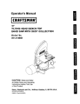
ITEM
A.
B.
C.
D.
DESCRIPTION
QUANTITY
Scroll saw
1
Blades (2 Pin-end and 2 Plain-end) 4
Hex wrench
1
Knob
1
STAND:
E.
F.
G.
H.
I.
J.
K.
L.
M
N.
O.
P.
Q.
Leg with leg flange
Legs
Top bracket
Top bracket
Bottom bracket (short)
Bottom bracket (long)
Foot pads
Bolt
Nut
Mounting hex Bolt
Flat washers
Screws
Nuts
1
3
2
2
2
2
3
1
1
4
4
20
24
UNPACKINGYOUR SCROLL SAW
la
,•
L
J
• i
• p
B
¢
D
I
I
/
o
_lJ o
o
i
J
I
J
I
I
I
I
\/
\/
K
o
0
0
J
/
G
V_
F
E
r_
0
/
Q
t
A
i
I
L
N
M
7
I
H
J
®Q
Q_
0
P
Q
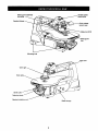
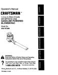
Bladeguardassembly
lockknob
Variable
speed
control
knob
tension
lever
-Bladelockknob
adeguard
foot
Mountinghole
UpperArm
Work light
Worktable
Bevel scale
Table lock knob
Sawdust
collection
Blade storage
8
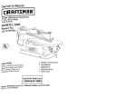
WOODWORKING
TERMS (FIG. A)
SCROLL SAW TERMS
KERF - The slot cut by the blade.
BEVEL SCALE- Represents the degree of table angle, from
0"to45", when the table is tilted for bevel cutting.
BLADE GUARD
ASSEMBLY
LEADING EDGE - The front edge of the workpiece which is
pushed intothe blade.
- Guards the blade arid keeps
SAW BLADE PATH- Area or line of sightof the workpiece
moving in line towardthe saw blade edge.
your workpiece from rising. Helps protect fingers from blade
contact.
BLADE TOOTH SET - The total blade cut width, based on the
distancefrom the outsidepoint of one bent tooth to the outside
pointof the next bent tooth.
BLADE GUARD ASSEMBLY LOCK KNOB - Allowsyou to
raise or lower the foot, and lock it at the desiredheight.
BLADE HOLDERS - Retain and positionthe blades.
TRAILING EDGE - The edge of the workpiece that the
sawblade will cut throughlast.
BLADE STORAGE - Providesconvenient easy access to
extra blades or wrenches.
SURFACE - Top of workpieca being cut.
QUICK RELEASE TENSION LEVER - Quickly loosensand
retightensthe blade to its original tension. The tension Lever
quicklysets and resets the blade tension when performing
interiorcuttingoperations or changing blades.
WORKPIECE - Material on which the cuttingoperationis
being performed.
FEED - Rate of movingworkpiece into the blade.
SAWDUST BLOWER - Keeps sawdust from coveringthe line
of sightfor more accurate cuts. The best results occur when
the blower tube is directed toward the blade and workpiece.
DEFLECTION - Slightmovement of blade in the horizontal
directionwhile the blade is movinginline during cutting
operations. This may be caused bythe blade followingthe
grain or the path of least resistance.
SAWDUST COLLECTION PORT - Allows vacuum
attachments or hose to be used to remove the sawdustfrom
underthe table and base.
TABLE LOCK KNOB - Securelylocks the table at the angle
Leading Edge
desired for bevel cutting.
Saw blade Path
Kerr
VARIABLE SPEED ON/OFF CONTROL KNOB - Variable
switchdial allows greater versatilitywhen cuttinga variety of
materials. Pull the control knob OUT to turn the scrollsaw ON.
Sudace
Adjustthe speed to the desired setting, between 400 to1600
strokesper minute (SPM), by turningthe control knob
clockwise or counter clockwise. Push the control knob IN to
turnthe scroll saw OFF.
Workpiece
9
Trailing Edge
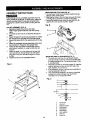
ASSEMBLY INSTRUCTIONS
This scrollsaw comes completely assembledfrom the
factory except for the leg set. To avoid injury,make sure
all parts are assembled and adjusted properlybefore
pluggingintoa power source outletor turningthis saw
ON.
MOUNTING SAW TO STAND (FIG. B)
1. To mountyour scrollsaw to the stand,positionthe leg
stand on a firm, level surface.
2. Matchingthe holes in the scrollsaw base with the holes
in the leg stand, place the scrollsaw on the stand.
3. Secure the stand and saw usingthe hex bolts(O), fiat
washers (P), and nuts (R) provided.Tighten.
Fig. B
LEG SET ASSEMBLY (FIG. A)
1. Separate all parts and group by size style.
Note: Finger tighten bolts and nuts whenjoining
parts.
2. Use bolts (Q) and nuts (R) to assemble the leg set
parts.
3. Attach the leg (G,F) to the long top bracket (I). Attach
the next leg to the opposite end of the top bracket.
4. Repeat this assembly for the oppositeside of the leg
set.
5. Attach the completed leg set assembliesto the short
top brackets (H). Repeat on the oppositeside.
6. Attach the two long bottom brackets (M) and two
shortbottom brackets (J), usingthe bolts(Q) and
nuts (R).
7. Attach the pads (L) to the bottomsof the legs and
insertbolt(M) into the leg flange hole and tighten
usingthe nut (N) turn the stand uprighton a level
surface.
8. Tighten all nuts with an adjustablewrench.
O
P
MOUNTING SAW TO WORKBENCH (FIG. C)
1. To mountyour scrollsaw in a permanentlocation
such as a sturdyworkbench,boltthe scrollsaw base
to a solidworkbenchtop. The scrollsaw base (1) has
4 mounting holes.
2. Place the scrollsaw on the work surface (5), mark the
holeson the work surface and drill3/8" holes. Use
bolts,washers, nuts to secure.
3. If the workbenchmovesor shakes duringoperation,it
mustbe fastened to the floor.
4. Your scrollsaw isdesignedto be used on horizontal
surfacesonly.Motor damage may resultwhen
mountedon a non-horizontalsurface.
Fig. A
F_
O
I
Fig. C
3
4
I
I I
II
5
@
1.
2.
3.
4.
5.
6.
7.
8.
9.
lO
"
I K
I I
Scroll saw
Hex bolt
Rubber washer
Flat washer
Workbench
Flat washer
Lock washer
Hex nut
Jamb nut
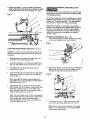
PLAIN-END BLADE REMOVAL (FIG. F, G, H, I)
1.To remove the blade (1), first loosenthe bladetension
by liftingthe quick release tension lever (2) locatedon
the saw's bladearm (3). (Fig, F)
BLADE STORAGE (FIG. D)
The bladestorage (1) is located under the table. Pull out
the blade storage (1) to open. The blade storage
convenientlystores your hex wrenches, and bothPin and
Plainend blades.
Fig. F
Fig. D
2. Loosen the upper blade holder (4) by turning the quick
release knob (5) counterclockwise(Fig. G).
Note: The hex set screw (6) on the left side is used
for fine adjustmentsand onlyneeds to be adjustedff
the blade is not perpendicular to the table.
SAWDUST
COLLECTION PORT (FIG. E)
To keep your saw cutting efficiently,you mustkeep the
saw base free of sawdust buildup. For that purpose,this
saw has a sawdust collectionport (1) thatwill accepta
vacuum hose (not provided).
If excessive sawdust buildupdoes occurinside the saw
base, there is a metal plate (2) attached by fourscrewsto
the left side of the saw (as viewed from the front). Take
out the screws and remove the metal plate. Clean out the
sawdustmanuallyor with a wet]dry vacuum. Reattachthe
metal plate.
Fig. G
6
Fig. E
3.Tilt the table to 0° and tightenthe bevel knob (7).
Loosen the lower blade holder screw (9) underthe
table on the left side of the lower blade holder (8) by
turning counterclockwise. (Fig+H)
Fig. H
2
BLADE
REMOVAL
9
AND INSTALLATION
\,l
PLAIN-END BLADE REMOVAL AND INSTALLATION
This scroll saw accepts 5 inch plain-end or pin-end
blades to cut a wide variety of materials.
Plain-end type blades are recommended whenever fine,
accurate, and intricate work is being performed on 3/4" or
thinner material. It will take slightly longer to install and
tension the blade, but you will be able to use finer blades
for cutting a thinner kerf.
To avoid injury from accidental starting, always turn the
switch OFF and remove power cord plug from power
source before removing or replacing the blade.
11
4.Remove
theblade(1),from
PIN-END BLADE REMOVAL AND INSTALLATION
Fig. I
To preventpersonalinjury, always turnthe saw OFF and
disconnectthe plug from sourcebefore changingblades
or makingadjustments.
the upper (4) and lower
blade holders(8) by pullingforward and liftingthe blade
throughthe access hole (10) in the table (11). (Fig. I)
2
Pin-end type blades are thicker for stability and for faster
assembly. These blades are required for faster cutting of
material 3/4" thickness or greater.
Also, use whenever
less precision or thicker kerf cutting is acceptable.
1
10
(
Note: When installingpin-end blades, the set screws
located on the upper and lower blade holdersshouldnot
be over or under tightened.The slot mustbe slightly
wider than the thicknessof the blade. After the blade is
installed,the blade tension mechanismwill keep the
pin-endin place.
3
PIN-END BLADE REMOVAL (FIG. J, K)
1. To remove the blade (1), loosen the tension by lifting
up the quick release tension lever (2) (Fig, J)
Fig. J
PLAIN-END BLADE INSTALLATION (FIG. F, G, H, I)
CAUTION: In order to avoid uncontrollable lifting of the
workpiece, the teeth of the blade should ALWAYS point
downward.
1.
Install the blade (1) through the access hole (10) in
the table (11) with teeth pointing down.
2.
Insert the new blade (1) into the lower blade holder
slot (13), then tighten the hex set screw (8). (Fig. I)
3. Tilt the table to the 0°bevel setting and lock the
bevel knob (7). (Fig. H)
4.
2,
Insert the other end of the blade into the upper blade
holder slot (12) and then tighten the quick release
knob (2) (Fig. G).
Remove the blade (1) from the upper (3) and lower (4)
blade holder by pulling it forward to release, then lift
the blade through the access hole (5). (Fig. K)
Fig. K
Note: Apply slight downward pressure against the
upper blade arm (7) when installing the blade into the
upper blade holder. (Fig. K)
5
J
Tighten the tension on the blade (1) by turning the
quick release lever (2) clockwise. Push the lock lever
downward. Check the tension on the blade. If too
loose, turn lever clockwise; do not make too tight or
blade will easily break in use. (Fig. F)
j5
[_
Note: The quick release lever handle must always be
clown to make the tension adjustments. Release the
quick release lever upward only during blade
changing operations
If the blade is over-tightened,
the lever is difficult to lower
3.
4
Tilt the table (6) to a 45 angle and lock the bevel
lock knob to view lower blade holder (4). (Fig. K)
Note: Appiy slight downward pressure on the upper
blade arm (7) of the saw when removing the blade
from the upper blade holder.
12
PIN-END BLADE INSTALLATION ( FIG. L,M )
CAUTION: In order to avoid uncontrollableliftingof the
workpiece, the teeth of the blade shouldalwayspoint
downward.
BLADE GUARD ASSEMBLY ADJUSTMENT (FIG. N)
When cuttingat angles, the bladeguard assembly(1)
shouldbe adjustedso it is parallelto the table and rests
fiat above the workpiece.
1. Install the blade (1) by insertingone end of itthrough
the access hole (6) or throat plate in the table. Hook
the lower blade pin in the pinrecess in the lower
blade holder (5) and then the upper blade pin in the
upper blade holder (4)(Fig. L).
1. To adjust, loosenthe screw(2), tiltthe foot so it's
parallelto table and tightenthe screw.
Fig. L
2.
Loosenthe knob(3) to raise or lowerthe foot until it
just restson top of the workpiece.Tightenknob.
Fig. N
16
7
2
SAWDUST BLOWER (FIG. O)
2.
Check to see that the pins are properly located in the
upper (4) and the lower (5) blade holders and move
the table (7) to the 0° bevel position by unlocking
the bevel lock knob.
The sawdust blower(1) should be positioned to point at
the blade and workpiece to blow sawdust out of the
line-of-sight when cutting. It is not designed to blow all of
the sawdust off the table.
3. To tension the blade (1), lower the quick release
tension lever (2). Check the tension on the blade; if
tension is too tight, turn the lever counterclockwise. If
tension is too loose, turn the lever clockwise (Fig. M).
Fig. O
Note: If the blade is over tensioned, the lever will be
difficult to lower and could result in damage to the
blade holder or blade arm assembly.
Fig. M
.3
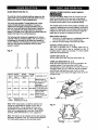
BLADE SELECTION (FIG. P)
VARIABLE SPEED CONTROL ONIOFF SWITCH
P_kVlVhl
;]_qLr_q_
To avoid injuryfrom accidental starting,alwaysturn the
switch"OFF" and unplugthe scroll saw before moving,
replacingthe blade, or making adjustments.
For yourown safety,always push the controlknobOFF
when the scrollsaw is not in use. Also, in the case of
powerfailure pushthe knob OFF. Remove the plugfrom
the power sourceoutletto avoidaccidentalstarting.
This scrollsaw accepts 5" length bladeswith a wide
varietyof blade thickness and widths. The type of
materialand intricaciesof cuttingoperations (size of
radiusor curve) will determine the number of teeth per
inch.As a general rule, always select the narrowest
bladesfor intricatecurve cuttingand the widest bladesfor
straightand large curve cuttingoperations.
The variable speed controlallowsgreater versatilityto cut
a variety of materialssuch as wood, plastics,non-ferrous
metals, etc. Dependingon the hardness and thicknessof
material, the saw speed shouldbe reduced to allowthe
blade teeth to remove cut materialfrom the kerf.
REPLACING THE BULB
1. Use only a (10 watt maximum), candelabra base bulb.
Turn the lightswitchOFF and unplugthe saw.
2. Remove old bulb. Replace new bulb intosocket.
The following table represents suggestionsfor various
materials.When purchasingblades, refer to the back of
the package for the best use of blades and speeds on
various materials. Use this table as a guide, but practice
and your own personal preference willbe the best
selectionmethod.
VARIABLE SPEED SWITCH (FIG. Q)
Your saw is equipped with a variable speed dial (1).
Adjust the blade stroke rate by rotating the dial. To
increase speed, rotate dial clockwise. To reduce speed,
rotate dial counterclockwise.
Fig. P
ON/OFF SWITCH (FIG. Q)
To turn power ON or OFF push the power switch (2).
9.5 - 15
TEETH/
INCH
TPI*
BLADE
WIDTH
INCH
15 - 28
BLADE
THICKNESS
OVERLOAD BREAKER (FIG. Q, R)
When the motor becomes too hot during operation,the
overloadbreaker (3) will cause the motor to stop
automaticallyto preventdamage to the motor.Push in on
the toggleswitch(2) to turn saw OFF and do not restart
until the motorhas had time to coot.Push in on the
breaker switch(3) and switchthe toggleswitch(2) to ON
to startthe saw
3O - 48
BLADE/
SPM**
MATERIAL CUT
INCH
9.5-15
0.110
0.018
15-28
.055-.110
.010-.018
3048
.024-.041
.012-.019
2
Fig. Q
Medium turns on
400-1200 114"to 1-314"wood,
soft metal and
hardwoods
Small turns on 1/8"
800-1800 to 1-1/2" wood, soft
metal, hardwoods
Use very slow
Varies
speeds on nonferrous metals and
hardwoods
f
* TPI:
Teeth per inch
** SPM: Strokes per minute
Note: When using blades, sometimes speeds must
change to compensate for smaller curves, radii, or
smaller diameters. Thinner blades will have more
possibilities for blade deflection when cutting angles
which are not perpendicular to the table. Read BASIC
SCROLL SAW OPERATION for more suggestions.
Fig. R
Note: The blade must be installed with the teeth pointing
downward, as shown in FIG. P, to prevent the workpiece
from being pulled upward by the saw blade action.
14
RECOMMENDATIONS
FORCUTTING
1,
FREEHAND CUTTING (FIG. S)
When feeding the workpiece intothe blade do not
force the leadingedge of the workpieceintothe blade
because the blade will deflect, reducingthe accuracy
of cut and possiblybreakingthe blade. Allow the saw
to cut material by guidingthe workpiece intothe
blade as it cuts.
To avoidinjuryfrom an accidentalstart, make Sure the
switch is in the OFF position and the plug is not
connected to the powe( sourceouUet.
1. Lay out desired design, or secure design to the
workpiece (1).
2. The blade teeth cut material ONLY on the down
stroke.
3. You must guide the wood intothe blade slowly
because the teeth of the bladeare very small and
wood is removedonly on the down stroke.
4.
5.
There is a learning curve for each personwho wants
to use this saw. Duringthat periodof time it is
expected that some bladeswill break untilyou learn
how to use the saw and receive the greatest benefit
from the blades.
2.
Raise the blade guard assembly (2) by loosening the
heightadjustmentknob (3).
3.
Positionthe workpiece against the blade (3) and
lowerthe blade guard assemblyagainstthe top
surface of the workpiece.
4.
5.
Best resultsare achieved when cuttingwoodless
than one inchthick.
6.
7. Teeth on scroll saw blades wear out and must be
replaced frequentlyfor best cuttingresults. Scro, saw
bladesgenerally stay sharp for 1/2 to 2 hoursof
cutting.
9,
Remove the workpiece from the bladeprior to tuming
the scroll saw ON. Pull the speed control knob (4) out
and set the desired speed by turning the control knob
clockwise or counterclockwise.
CAUTION: In order to avoid uncontrollable lifting of
the workpieceand to reduce blade breakage, do not
pull the controlknob ON while the workpieceis
againstthe blade..
6. When cutting wood thicker than one inch the user
must guide the wood very, very slowlyinto the blade
and take extra care not to bend or twist the blade
while cutting in order to maximize blade life.
8.
Secure the blade guard assembly(2) by tightening
the heightadjustment knob (3).
Slowly feed the workpiece into the blade, pressing
the workpiece down against the table while cutting.
CAUTION : Do not force the leading edge of the
workpiece into the blade. The blade will deflect,
reducingaccuracyof cut, and may break.
To get accurate cuts be prepared to compensate for
the blade's tendency to follow the wood grain as you
are cutting.
7. When the cut is complete, move the trailingedge of
the workpiece beyond the blade guard foot. Push the
controlknob in to turn the scroll saw OFE
This scroll saw is intended to cutwood or wood
products.Precious and non-ferrousmaterials perform
well on scrollsaws that have very slow speed
capability,and shouldbe lubricated with machine oil
or beeswax.
Fig. S
10. When choosing a blade to use with your scrollsaw,
use very fine, narrow blades to scrollcut thin wood of
1/4-inch or less thickness. Use wider blades for
thicker materials but wider blades will reduce the
ability to cut tight curves.
11. Blades wear faster when cutting abrasive materials
like plywoodor particleboard. Angle cuttingin
hardwoodsreduces blade toothset faster due to
blade deflection.
15
ANGLE
cu'n'ING(FIG.T)
RIPORSTRAIGHT
LINECUTTING
(FIG.U)
Toavoidinjuryfrom
an accidental starting,make sure the
switchis in the OFF positionand the plug is not
connectedto the power source outletbefore moving,
replacingthe blade or making adjustments.
To avoid injuryfrom an accidentalstarting,make sure the
switchis in the OFF positionand the plug is not
connectedto the powersource outletbefore moving,
replacingthe blade or making adjustments.
1.Lay out or secure design to workpiece (1).
Tools Needed
QUANTITY
2
1
1
2. Move the blade guard assembly (2) to the highest
positionby looseningthe height adjustmentknob (3)
and retighten.
3. Tiltthe table (4) to the desired angle by loosening the
bevel lock handle (5) and moving the table to the
proper angle, using the degree scale (6) and the
pointer (7).
1. Raise the blade guard assembly (1) by loosening the
height adjustment knob (2) on the right side of the
upper blade arm. Position the straight edge (4)
parallel to the blade at the desired ripping distance.
2. Clamp the straight edge (4) to the table (5).
3. Recheck your measurements, using the workpiece to
be cut, and make sure the scrap wood is secure.
4. Position the workpiece against the blade and place
the blade guard assembly (1) against the top surface
of the workpiece.
5. Secure the blade guard assembly in place by
tightening the height adjustment knob.
6. Remove the workpiece from the blade prior to turning
the scroll saw ON. Pull the speed knob control out
and set the desired speed by turning the control knob
clockwise or counterclockwise.
CAUTION: In order to avoid uncontrollable lifting
of the workpiece and reduce blade breakage, do not
pull the control knob ON while the workplace is
against the blade.
7. Position the workpiece against the straight edge (4)
prior to touching the leading edge of the workpiece
against the blade (3).
8. Slowly feed the workpiece into the blade, guiding the
workpiece against the straight edge and pressing the
workpiece down against the table while cutting.
CAUTION: Do not force the leading edge of the
workpiece into the blade. The blade will deflect,
reducing accuracy of cut, and may break.
9. When the cut is complete, move the trailing edge of
the workpiece beyond the blade guard assembly.
Push the controlknob in to turn the scroll saw OFE
NOTE: When cutting a narrow workpiece use push
sticks.
4. Tighten the bevel lock knob (5).
5. Loosen the blade guard screw (8), and tiltthe blade
guard to the same angle as the table (4). Retightan the
blade guard screw.
6. Position the workpiece on the left and right side of the
blade (9). Lower the blade guard assembly against the
surface by loosening the height adjustment knob (3).
7. Follow items 4-8 under FREEHAND CUTTING
OPERATION.
Fig. T
'\
DESCRIPTION
Small C-clamps
Ruler or measuring tape
12" Straight scrap of wood
(Thickness to match workpiece)
1
4
Fig. U
16
INTERIOR CUTTING (FIG. V)
....
1. Lay out the design on the workpiece (I). Drilla I/4"
hole in the workpiece.
P_Wkvlv/_,W
d _11_
[_
2. Release the tension knob (2), and remove the blade (3).
Refer to BLADE REMOVAL AND INSTALLATION.
For yourown safety,turn the switchOFF and removethe
plug from the power source before maintainingor
lubricatingyour saw.
3. Place the workpiece on the saw table with the
workpiece hole over the access hole(4) in the table.
GENERAL
An occasionalcoat of paste wax on the work table will
allowthe wood beingcut to glide smoothlyacrossthe
work surface.
4. Install the blade (3) throughthe hole in the workpiece
and access hole (4) and lower the quickrelease
tension lever (2).
MOTOR
1. If the powercord isworn, cut, or damaged in anyway,
have it replaced immediately.
5. Followthe process, items 3-g, under FREEHAND
CUTTING OPERATIONS.
6. When finished making the interiorscrollcuts turn the
scroll saw OFF, remove the blade from the blade holder,
and remove the workpiece from the table.
Fig. V
2. Do not attemptto oil the motor bearings or servicethe
motor internal parts.
UPPER ARM BEARINGS (FIG. W)
Lubricate the upper arm bearings after every 50 hoursof
use.
1. Carefully lay the saw on its side.
2. Loosenthe bushing with an 8mm hex key.
3. Squirt a generous amount of SAE 20 (lightweight)oil (11
around the shaft end and bearing (2).
4. Let the oil penetrate the bearing assembly overnight.
5. Replace and tighten. Turn the scroll saw over and
repeat on the other side.
Fig. W
17
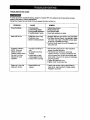
TROUBLESHOOTING GUIDE
To avoid injuryfrom accidental starting,alwaysturn switchOFF and unplugthe scrollsaw before moving,
replacingthe blade or making adjustments.
Contact your Sears Service Center if for any reasonthe motorwillnot run.
PROBLEM
CAUSE
REMEDY
Breakingblades
1. Wrong tension.
2. Overworkingblades.
3. Wrong blade application.
4. Twistingblade in wood.
1.Adjust bladetension.
2. Reducefeed rate.
3. Use narrowblade.
4. Avoid side pressure on blade.
Motor will not run.
1. Defective cord or plug.
2. Defective motor.
3. Blownovedoad breaker,
1. Replace defective parts before usingsaw again.
2. Call Sears Service Center. Any attempt to repair
this motor may create a HAZARD unlessrepair
is done bya qualifiedtechnician.
3. Push the motorswitchto the OFF position.Let
the motorcoo!.
Excessive vibration.
NOTE: There will
always be some
vibrationpresentwhen
the saw is running
because of motor
operation.
1. Improper mountingof
saw.
2. Unsuitablemounting
surface.
3. Loosetable or table
resting against motor.
4. Loose motormounting.
1. See mounting instructionsin this manualfor
proper mounting technique.
2. The heavier yourworkbenchis the less
vibrationwilloccur.A plywoodworkbenchwill
not be as goodwork surface as the same size
solid lumber.Use common sense in choosinga
mountingsurface.
3. Tightenthe table lock knob.
4. Tightenmotor mountingscrew.
Blade not in line with
blade arm motion,
1. Blade holders not
aligned,
1. Loosen cap screws holding blade holder to
blade arms. Adjust position of blade holders,
Retighten cap screw.
18
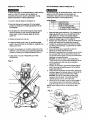
19
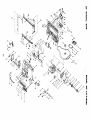
20" SCROLL
SAW
MODEL
NO. 137.216200
When servicinguse only CRAFTSMAN replacement parts. Use of nay other parts may create a HAZARD or cause
productdamage.
Any attempt to repair or replace electrical parts on thisscroll saw may create a HAZARD unlessrepair is done bya
qualifiedservice technician. Repair service is available at yournearest Sears Service Center,
ORDER ONLY BY MODEL NUMBER AND PART NUMBER
Key
Pad No.
Der.cdptlon
1
11A00101
PLUNGER HANDLE
2
2501MBDN31
FLAT WASHER
3
14403301
SPRING
4
11A00401
5
6
Q_y
Oty
Key Pad No.
Descdpflon
81
16721602
BELLOWS
62
11A12901
PLUG HOUSING
83
2636BBDA07
CR RE COUNT HD SCREW
TENSION HANDLE
B4
2504MZC004
EXTERNAL
11AB0601
TILTING SCALE
55
2653MZDE11
CR RE TRUSS HO TAPPING SCREW M4X16*12
1 tA00701
TRUNNION
56
18515401
RETAINING
7
2668BBDA08
CI_ RE. PAN HD. SCREW
M4X0.7-10
67
2620BSDC05
CR,RE
8
26171BBLB19
HEX SOC. HD. CAP BOLT
M6X1 0-12
68
19A10701
PLUNGER HOUSING
9
2637BBDA70
CR RE. TRUSS
M6X1,0-23
59
2617BBLC20
HEX.SOCKET
10
11A01101
NEEDLE POINTER
_'o_
_.2_o
_7_.
_ _0_
L,. ,u:E?F.._.u_
...............................................................................
11
11A01201
BRACKET TILT
Z1
11A13901
TRADE-MARK
12
2983AL5010
STEEL BALL
Z2
16702001A2
BEARING SEAT ASS'Y
13
16203001
COMPRESSION
73
20105PBA05
SPHERICAL
14
2668BBDA25
CR. RE. PAN HD SCREW
74
11A15802
BUSH
15
11A01601
DUST COLLECTOR
?5
14701101
WASHER
?6
11A16002A1
ECCENTRIC
16
Size
_ 0X18-1 5
8RACKET
HD SCREW
SPRING
M5X08
16
JOINT
N/A
Size
M4XO.7-8
TOOTH LOCK WASHER
RING
PAN HO SCREW S WASHER
HDCAP
SCREWS
M6X1 0 25
M6XI
0-25
LABEL
BEARING
ASS'Y
17
2603BBLA66
HEX SOC
SET SCREW
M10X1._12
T/
181O50O2
BLADE
18
2602BBLA58
HEX. SOC
HD. CAP SOLT
M8X1 25*35
?8
15802104
BLADE
?9
17104403A1
HOLDER BLADE ASS'Y
1
_0
11A16801A1
BOTTOM
1
31
2501MBDN06
FLATWASHER
_ 6X13-1
t
32
2705FBD105
NUT CHUCK
MSX08 T=5
1
33
15802301
BEARING SEAT
I
_4
2602BBLA08
HEX SOC
2
35
14706601
SET P{J_TE
19
N/A
20
11A02201
BASE
21
2705FBD108
NUT CHUCK
22
11A02401
TABLE
23
11A02501
INSERT
24
2668BBDA24
CR, RE, PAN HD SCREW
25
11A02701
RETAINING
26
11A02801
BLADE BOX
27
2138MBL703
WRENCH
25
2617BBLB58
HEX,SOCKET
29
MBX1 25 T=8
MSX0 8-12
CLIP
HF_X,
HD,CAP SCREWS
ARM
ROCKER
ASS'Y
HD CAPBOLT
I
36
2617BBLO13
HEX SOCKET HD CAP SCREWS
3-57
1
)7
11A17901A1
LINGAGE BAR ASS'Y
M8X1 25-35
1
38
11A18001
EXTENSSION
)9
2677SBDAA3
CR.RE
N/A
M4X07-10
M5X0.840
SPRING
PAN HD ROUND NECK SCRE M4X0.7*7 5
.:_,..,,._
_0_'_C_pL.S_R.!_..W'_S,
HE_
...............................
'_._
.............................
31
11A03401
CAUTION
32
2501MWTN63
FLAT WASHER
LABEL
)1
18105001
BLADE
PLAIN 12.5
)2
17102701
BLADE
33
11A03601
TRADE=MARK LABEL
PIN 10T
)3
15802103
BLADE
34
2637BBOA39
CR RE TRUSS
PIN 18T
)4
8586128827
MOTOR
35
11A10101
36
11A10201
PLATE COVER
)5
2637BBDA39
CHORE TRUSS HO SCREW
M6X1 0-12
LABEL
)6
2617BBLC21
HEX SCCKET HD CAP SCREWS
37
16730102A1
M6X1 0-16
AIR DUCT ASS'Y
)7
11A25401
SWITCH BOX
_p25 5X35-2 5
HO, SCREW
M6X1 O-12
38
16730001
PVC HOSE
)5
2660MBCE14
CR.RE
39
11A10501
CLAMP PLATE
)9
11A25601
SWITCH BOX COVER
:_L.?_.....,_.EX..S_L._ET..'%REW
......................
_6_.6 ..................
IO0 ,_P
PAN HD TAPPING SCREW
BCK ! 5...... CR.RE...I_:_r_.1_[_.TAPP!NG.SCREW
M4X16-16
.....M4X18:20 ...............
41
11A10701
PLUNGER
HOUSING
101 2852U55722
ROCKER SWITCH
42
11A10901
SUPPORT
ROD
102 1IA25901
INDICATED BUTTON
43
16700805
CLAMP HANDLE
103 2701FBO107
HEX. NUT
MBX1 25 T=
44
11Al1101
CLAMPER
104 2501NBDN59
FL_T WASHER
5/32X13/32=
45
11Al1202
HOUSING
105 2660MSCK16
CR.RE PAN HD TAPPING SCREW
MSX08-10
46
18402702
DUST SHIELD
,06
1IA26302
HOUSING RIGHT
47
2660PBCK40
CR RE PAN HD TAPPING SCREW
'07
19A10101
CLAMP-CORD
48
11Al1501
CONNECTOR
08
11A26501A1
LAMP ASS'Y
49
11A11601A1
CONTROLLER
09
11A27C01
STICKER
M5X16-50
BOX
ASS'Y
._L...2_PMBC_O_....._.R:RE:.£'_ff._O.:[ft_!'_P..S_E"Y.M.?_._
....................
_.L_9_p.!2%.........C_M
£:_(_
_{_.............................................................................
51
11A11801
CONNECTOR
52
53
2660PBCK23
2553055714
CR RE PAN HD TAPPING SCREW
CtRCU}T BREAKER SWITCH
BOX COVER
2801UBHA07
STRAIN RELIEF
56
280655581 Y
LEAD W_RE ASS*y
56
2807BBQ8HB
POWER CABLE
57
19A10901
SHAFT PIVOT
58
2501MBDN21
FLAT WASHER
59
2506MBN606
WAVE
60
2705FBD106
NUT CHUCK
M4X18 25
_pBX16-1 4
WASHER
20
11 2660MBCB14
CRRE
12 1_A27301
WARNING LABEL
PANHO
TAPPING SCREW
88
<
56
86
54
51
53
I
524
65
64
49
10
9
6
• 0
4
m
r_
43
az
" Z
o
56
".4
io
o)
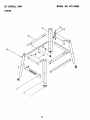
ORDER ONLY BY MODEL NUMBER AND PART NUMBER
Key Part No.
1
17010103
Descrlptiof
SPACER
S_e
2
17050111
SUPPORT BRACKET
L=7483
3
17050511
BOTTOM SUPPORT BRACKET
L=428
4
2672BBDA54
CAP HD. SQ.NECK BOLT
M8x1.25-16
5
17050313
UPPER SUPPORT BRACKET
L=243
2
6
2708FBD112
SERRATED TOOTHED HEXAGON FLANG NUT
M8x1.25 T=7.5
24
7
17050412
BOTTOM SUPPORT BRACKET
L=810
2
8
17050215
UPPER SUPPORT
L=630
2
9
17050112
SUPPORT BRACKET
L=748.3
1
10
2701QBD509
HEX. NUT
318"X16UNC T=8
1
11
1A213201
SPACER
12
2601BBDA66
HEX. HD. BOLT
13
2501MBDN21
14
17050510
Q_/
3
3
1
20
1
MSx1.25-70
4
FLATWASHER
fp8x16-1.4
4
BOTTOM SUPPORT BRACKET
L=428
1
22
20" SCROLL SAW
MODEL NO. 137.216200
STAND
3
_3
23
For repair of major brand appliances in your own home...
no matter who made it, no matter who sold it7
1-800-4.-MY-HOM EsuAnytime,day or night
(1-800-469-4663)
www.sears.com
To bring in products such as vacuums, lawn equipment and electronics
for repair, cell for the location of your nearest Sears Parts & Repair Center.
1-800-488-1222
Anytime, day or night
www.sears.com
For the replacement parts, accessories and owner's manuals
that you need to do-it-yourself, call Sears PartsDirect s"!
1-800-366-PART
s a.m.-
(1-800-366-7278)
11 p.m. CST,
7 days a week
._4_
www.sears.condpartsdirect
To purchase or inquire about a Sears Service Agreement:
_:_
1-800-827-6655
7 a.m. - 5 p.m. CST, Mon. - Sat.
Para pedir servicio de reparacibn a domicilio,
y para ordenar piezaS con entrega a domicilio:
1-886-SU-HOGAR
s.
(1-888-784-6427)
Au Canada pour service en fran_.ais: ! _!_
1.877.LE.FOYER
(1 877 533-6937)
s"
_
..........
.....
_:_iiiiiiiiiili:
I HorneCentral"
S ARS !
® Regist_ed
O Sears, Roebu d_ and Co.
Mama
Trademark
Registrada
/
TM
/ i,* Trademark
Marc_
de F;ibnca
o( Seam,
de Sears,
Roebuck
Roebuck
and Co.
and Co.
2/2002