1
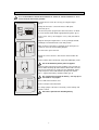
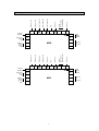
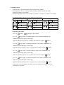
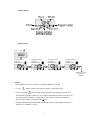
MGE - MHP
Owner’s Manual – Installation and Operating Instructions
Please read this manual carefully before installation and use.
Index
Installation Instructions
1
Wiring Connections
2
Hardware Jumpers
3
Operating Manual
4
SET
ON
ALARM
ON/OFF
SET
TEMP
ALARM
LIMITS
PROG CLOCK SELECT MODE AUTO RESET
FAN
mge-mhp-rheem-new2-new
Rev. 4 10/8/2010
1. Installation Instructions
It is recommended to mount the thermostat or return air sensors between 1.5 & 1.8
meters from the floor where possible.
Separate the base from the cover by pressing the tongue
(pic.1).
Spring tongue
Gently disconnect the cover from the base with quick
connector (pic.2)
Line the back panel up against the wall or flat surface on which
it is to be mounted and drill the appropriate fixing holes (pic.3).
Spring tongue
Pic.1
Quick connector
Insert screws so they extend approx. 3/16" (3 mm) from wall or
surface.
Align the back panel against these screws, pushing it forward,
allowing it to slide downwards to lock into position.
Make electrical connections to terminals on the back panel as
shown on enclosed electrical wiring diagram
Reconnect the quick connector.
Shafts
Pic.2
Attach the cover to the base, first the two shafts and then the
spring.
Connect 24Vac to the thermostat; verify that LCD display is ON.
Do not install battery before power is applied.
Pic.3
Remove battery from back panel by sliding it to the left and out
from its white retaining clip and mount it in black holder on front
panel; insert it from the top, gently pressing downwards until it
snaps into place and is held under the top clip of the holder.
The ‘+’ engraved on battery should be visible (pic. 4).
Be careful when inserting the battery – the top clip of
the holder is very fragile.
Back panel
Front panel
Reassemble front and back cover.
Connect at top first then at bottom.
+
Battery Holder
Pic.4
To change jumpers: Disconnect electricity, remove battery and
wait 60 seconds
Disconnect power before installing battery
2
Fault IN
(24VAC)
Heat element 3
W2
W3
HU
G1
G2
FD
AL
Not in use
Heat element 2
W1
B/O
Alarm
(Dry contact
normally open)
Heat element 1
Y2
Not in use
Compressor 2
Y1
Fan
Compressor 1
2. Wiring Connections
AL
AUX
Rc
Rh
AB
Return air
sensor
(T1)
T1
C
T1
14
Outdoor
Temp.
Sensor
(NA)
T0
Fault IN
(24VAC)
MGE
15
External
IR
Reciever
W1
B/O
W2
W3
HU
G1
AUX
G2
FD
AL
Not in use
Alarm
(Dry contact
normally open)
Not in use
Fan
Not in use
Y2
Heat element
Y1
Heat pump
Compressor 2
16
Compressor 1
T0
Main
supply
24VAC
AL
Rc
AB
Rh
Return air
sensor
(T1)
T1
C
T1
14
Outdoor
Temp.
Sensor
(NA)
T0
MHP
T0
15
16
3
Main
supply
24VAC
External
IR
Reciever
3. Hardware jumpers
3.1 The Jumpers are located on the back of the front panel (Inside the thermostat) as shown
in the drawing.
Table 3.1 – Jumper selection
Hardware
jumpers
JP3-JP7
Screws to hold
PCB to plastic
Jumper Short
When the black
JP1 to select
cover is placed on
internal or
the 2 legs.
external
Jumper Open
temperature
When the 2 legs
sensor with 2
of the Jumper are
positions A and B
NOT SHORTED
Jumper
JP1
JP3
JP4
JP5
JP6
JP7
Function
Position
Internal Sensor Control
Pos. A
External sensor control
Pos. B
4 minutes delay for compressor
Open
No delay
Short
Clock mode – 24 hours
Open
Clock mode – 12 hours (AM/PM)
Short
Temperature in Fahrenheit
Open
Temperature in Celsius
Short
Europe timer type
Short
Reversing Valve (W1) output in heating mode (eg Rheem)
Short
Reversing Valve (W1) output in cooling mode (eg FHP)
Open
4
Default
Pos. A
Open
Open
Short
Short
Short
4. Operating Manual
4.1 Thermostat display
In normal display mode, the LCD alternates between real time
clock and set/room temperatures.
SET
CLOCK
Hours
TEMP
Settemperature
Minutes
Room
temperature
4.2 On/Off
• Press the
button to turn the thermostat ON.
When on – the “SYSTEM” LED will turn on.
button to turn the thermostat OFF.
• Press and hold the
4.3 Selecting modes
• Press the
button to switch between the four modes:
1. Fan only - When ventilation only needed.
2. Cooling
1. Fan
3. Heating
3. Heat
HEAT
4. Cool/Heat - Auto change-over
Activating Heating or Cooling automatically
2. Cool
according to the set and room temperatures.
COOL
The current active mode will flash.
4.4 Set temperature
• Press the
buttons – the word “SET” will flash.
o
• Adjust the set temperature using the
SET
buttons (range: 5-35 C).
TEMP
COOL
Settemperature
Room
temperature
5
4. Auto change-over
HEAT
COOL
4.5 Auto fan
• Press the
button to switch between “fan on” and “auto fan” modes.
In “auto fan” mode – the fan will work only when there is demand for cooling or heating.
AUTO FAN
4.6 Real time clock and day
Adjust the hours
• Press the
button - the hours will flash.
• Adjust the hours using the
button.
Adjust the minutes
• Press the
button again – the minutes will flash.
• Adjust the minutes using the
button.
Set the day
• Press the
button again – the days will flash.
• Set the day using the
• Press the
button.
button again to return to normal display.
6
4.7 Weekly Program
The thermostat can be activated and deactivated using a weekly program.
Different programs can be set for the weekdays (Monday to Friday), Saturday and Sunday
(all weekdays with the same program).
st
st
Two different programs can be set for each day (1 start time, 1 stop time, 2
nd
nd
start time, 2
stop time).
The following program chart can assist you during the program settings.
Monday Friday
Saturday
Sunday
__:__
__:__
__:__
__:__
__:__
__:__
__:__
__:__
__:__
__:__
__:__
__:__
Programming procedure
• Press the
button -
will appear on the display
• Press the
button again – the HOURS will flash and the START, PROGRAM 1 and
MONFRI symbols will appear on the display.
st
• Adjust the start time (hours) for the 1 program of the weekdays using the
• Press the
buttons.
button again – the MINUTES will flash and the START, PROGRAM 1 and
MONFRI symbols will appear on the display.
st
• Adjust the start time (minutes) for the 1 program of the weekdays using the
• Press the
buttons.
button again – the HOURS will flash and the STOP, PROGRAM 1 and
MONFRI symbols will appear on the display.
st
• Adjust the start time (hours) for the 1 program of the weekdays using the
• Press the
buttons.
button again – the MINUTES will flash and the STOP, PROGRAM 1 and
MONFRI symbols will appear on the display.
st
• Adjust the start time (minutes) for the 1 program of the weekdays using the
buttons.
• Repeat these steps for program 2 (weekdays), for the two programs of Saturday and for the
two programs of Sunday.
7
Program display
Program layout
Press to start
PROG
Start time (hours)
Program 1
Monday-Friday
MON TUE WED THU FRI
START
Stop time (hours)
Program 1
Monday-Friday
Start time (minutes)
Program 1
Monday-Friday
PROGRAM
1
PROG
MON TUE WED THU FRI
START
PROGRAM
1
PROG
MON TUE WED THU FRI
PROGRAM
STOP
1
Stop time (minutes)
Program 1
Monday-Friday
PROG
MON TUE WED THU FRI
PROGRAM
STOP
1
PROG
Repeat these steps
for the other
programs
Remarks
Every program must have a start time and stop time within the same day.
Use the
button for quick review/edit the program – jump between days.
Press and hold the
button to switch between program mode (program activated) and
manual mode (program not activated) – the program settings will remain in the memory of the
thermostat until the program is reactivated (this can be done only when the thermostat is
ON). An active program is indicated by the
icon.
During programming the thermostat will automatically return to normal display mode when no
button is pressed within 5 seconds.
8
4.8 Technician Settings
• Press the
button – “C50” will appear on the display.
• Change the number to “55” using the
buttons.
High temperature limit
• Press the
button again – “HL” and the high temperature limit will appear on the display.
o
• Adjust the high temperature limit using the
buttons (range: 4-39 C, do not set the high
o
temperature limit higher than 31 C where cooling is used).
Low temperature limit
• Press the
button again – “LL” and the low temperature limit will appear on the display.
o
buttons (range: 2-30 C, do not set the low
• Adjust the low temperature limit using the
o
o
temperature limit lower than 18 C where cooling is used or lower than 16 C where heat
pump is used).
9
High temperature alarm
• Press the
button again – “HL” and the high temperature alarm will appear on the display.
• Adjust the high temperature limit using the
o
buttons (range: 4-46 C).
Note: When the alarm activates, the AL,AL outputs will activate and the ALARM red LED will flash.
Low temperature alarm
• Press the
button again – “LA” and the low temperature alarm will appear on the display.
o
buttons (range: 2-44 C).
• Adjust the low temperature limit using the
Note: When the alarm activates, the AL,AL outputs will activate and the ALARM red LED will flash.
Reset the alarm
The alarm will automatically clear itself when the temperature returns to normal range.
The alarm can be manually cleared by pressing and holding the
10
button
Contacts
In the unlikely event of a problem with this Rheem controller you should contact the installing contractor.
Please write their details below:
Importer
The exclusive importer of Rheem Air Conditioners and Heat Pumps for the UK is Medal Aircon
Accessories Ltd and their email address is www.medalaircon.co.uk .
They may be contacted on 01743 466333 or by fax on 01743 466334.
Alternatively email them at [email protected]
11
12