1
I CRRFTSMRN 1
Operator's
Manual
Snow Thrower
9 Horsepower
Electric Start
Dual Stage
Model 536.887994
CAUTION: Before using this product,
read this manual and follow all of its
Safety Rules and Operating Instructions.
Manual del usario
Quitanieves
9 caballos de fuerza (hp)
Biet&pico
Arranque el_ctrico
Modelo
536.887994
PRECAUCION: Antes de usar este producto,
lea este manual y siga todas las reglas de
seguridad e instrucciones de operaci6n.
Sears, Roebuck
F-0310107L
and Co., Hoffman Estates,
www.sears.com/craftsman
IL 60179 U.S.A.
nl:l -I ! :llo]i[ilo]l I I 11 lt,
WARRANTY STATEMENT ......
SAFETY RULES ...............
INTERNATIONAL SYMBOLS ....
ASSEMBLY ...................
OPERATION ..................
MAINTENANCE
...............
SERVICE AND ADJUSTMENT
..
2
2
4
6
10
16
19
STORAGE ....................
29
TROUBLESHOOTING
TABLE . ..
30
REPAIR PARTS ...............
34
ENGINE REPAIR PARTS .......
52
SPANISH (ESPAI%IOL) ..........
61
PARTS ORDERING/SERVICE
..
BACK COVER
iflvh.lzt z#:!l i i'it:t
LIMITED
TWO-YEAR
WARRANTY
f:l d!_viI1 lid
ON CRAFTSMAN
SNOW
THROWER
For two years from the date of purchase, when this Craftsman Snow thrower is maintained,
lubricated, and tuned up according to the operating and maintenance instructions in the
owner's manual, Sears will repair, free of charge, any defect in material or workmanship.
If this Craftsman Snow thrower is used for commercial or rental purposes, this warranty applies for only 90 days from the date of purchase.
This warranty does not cover the following:
Items which become worn during normal use, such as spark plugs, drive belts and shear
pins.
Repair necessary because of operator abuse or negligence, including bent crankshafts
and the failure to maintain the equipment according to the instructions contained in the
owner's
manual.
WARRANTY
SERVICE IS AVAILABLE BY RETURNING THE CRAFTSMAN
SNOW
THROWER TO THE NEAREST SEARS SERVICE CENTER IN THE UNITED STATES.
THIS WARRANTY APPLIES ONLY WHILE THIS PRODUCT IS IN USE IN THE UNITED
STATES.
This warranty gives you specific legal rights, and you may also have other rights which may
vary from state to state.
Sears, Roebuck and Co., D817WA, Hoffman Estates. [L 60179
_lb
IT MEANS-- ATTENTION!!! BECOME ALERT!!! YOUR SAFETY IS INVOLVED.
OOK FOR THIS SYMBOL TO POINT OUT IMPORTANT SAFETY PRECAUTIONS.
nect
the spark
plug
wire
WARNING:
Always
disconand place it where it cannot
make contact with spark plug to
prevent accidental starting during:
Preparation, Maintenance, or Storage of your snow thrower.
_i
Engine Exhaust, some of its constituents, and
certain vehicle components
contain or emit
chemicals known to the State of California to
cause cancer and birth defects or other reproductive harm.
Battery posts, terminals and related accessories
contain lead and lead compounds, chemicals
known to the State of California to cause cancer
and birth defects or other reproductive
harm.
WASH HANDS AFTER HANDLING.
F-0310107L
2
IMPORTANT:
Safety standards require operator presence controls to
minimize the risk of injury. Your snow
thrower is equipped with such controls.
Do not attempt to defeat the function of
the operator presence control under any
circumstances.
TRAINING
1.
8.
Read this operating and service instruction
manual carefully. Be thoroughly familiar
with the controls and the proper use of the
snow thrower. Know how to stop the snow
thrower and disengage the controls quick-
snow
Never allow children to operate the snow
thrower. Never allow adults to operate the
snow thrower without proper instruction.
3.
Keep the area of operation clear of all persons, particularly small children and pets.
4.
Exercise caution to avoid slipping or falling
especially when operating in reverse.
PREPARATION
2.
3.
4.
1.
Thoroughly inspect the area where the
snow thrower is to be used and remove all
doormats, sleds, boards, wires, and other
foreign objects.
5.
2.
Disengage all clutches before starting the
engine (motor).
Do not operate the snow thrower without
wearing adequate winter outer garments.
Wear footwear that will improve footing on
slippery surfaces.
6.
3.
4.
Handle fuel with care; it is highly flammable.
a.
Use an approved fuel container.
b.
Never remove fuel tank cap or add fuel
to a running engine (motor) or hot engine (motor).
Fill fuel tank outdoors with extreme
care. Never fill fuel tank indoors.
c.
d.
e.
f.
5.
6.
7.
7.
8.
Replace fuel cap securely and wipe up
spilled fuel.
Never store fuel or snow thrower with
fuel in the tank inside of a building
where fumes may reach an open flame
or spark.
9.
Check
lowing
of the
cause
10.
fuel supply before each use, alspace for expansion as the heat
engine (motor) and/or sun can
fuel to expand.
For all snow throwers with electric starting
motors use electric starting extension
cords cartified CSA!UL. Use only with a receptacle that has been installed in accordance with local inspection authorities.
Never attempt to make any adjustments
while the engine (motor) is running (except
when specifically recommended by manufacturer).
Let engine (motor) and snow thrower adjust to o_door temperatures before starting
to clear snow.
F-0310107L
thrower.
OPERATION
1.
2.
Always wear safety glasses or eye shields
during operation or while performing an adjustment or repair to protect eyes from
foreign objects that may be thrown from the
11.
12.
Do not operate this snow thrower if you are
taking drugs or other medication which can
cause drowsiness or affect your ability to
operate this snow thrower.
Do not use the snow thrower if you are
mentally or physically unable to operate the
snow thrower safely.
Do not put hands or feet near or under rotating parts. Keep clear of the discharge
opening at all times.
Exercise extreme caution when operating
on or crossing gravel drives, walks or
roads. Stay alert for hidden hazards or
traffic.
After striking a foreign object, stop the engine (motor), remove the wire from the
spark plug, thoroughly inspect snow
thrower for any damage, and repair the
damage before restarting and operating
the snow thrower.
If the snow thrower should start to vibrate
abnormally, stop the engine (motor) and
check immediately for the cause. Vibration
is generally a warning of trouble.
Stop the engine (motor) whenever you
leave the operating position, before unclogging the anger/impeller housing or discharge chute and when making any
repaire, adjustments, or inspections.
When cleaning, repairing, or inspecting,
make certain the augedimpeller and all
moving parts have stopped and all controls
are disengaged. Disconnect the spark plug
wire and keep the wire away from the spark
plug to prevent accidental starting.
Take all possible precautions when leaving
the snow thrower unattended. Disengage
the auger/ impeller, stop engine (motor),
and remove key.
Do not run the engine (motor) indoors, except when starting the engine (motor) and
for transporting the snow thrower in or out
of_qe building. Open the outside doors; exhaust fumes are dangerous (containing
CARBON MONOXIDE, an ODORLESS
and DEADLY GAS).
Do not clear snow across the face of
slopes. Exercise extreme caution when
changing direction on slopes. Do not attempt to clear steep slopes.
Never operate the snow thrower without
proper guards, plates or other safety protective devices in place.
13.Never
operate
thesnow
thrower
near
en- MAINTENANCE AND STORAGE
closures,
automobiles,
window
walls,
drop- 1. Check shear bolts and other bolts at fre_
offs,
andthelikewithout
proper
adjustment quent intervals for proper tightness to be
ofthesnow
discharge
angle.
Keep
children sure the snow thrower is in safe working
andpetsaway.
condition.
14.Donotoverload
thesnow
thrower
capacity2. Never store the snow thrower with fuel in
byattempting
toclear
snow
attoofasta
the tank inside a building where ignition
rate.
sources are present such as hot water and
15.Never
operate
thesnow
thrower
athigh
space heaters, clothes dryers, and the like.
transport
speeds
on slippery
surfaces. Allow the engine (motor) to cool before
Look
behind
andusecarewhen
backing storing in any enclosure.
up.
3.
Always refer to operator's guide instruc16.Never
direct
discharge
atbystanders
or
tions for important details if the snow
allow
anyone
infront
ofthesnow
thrower. thrower is to be stored for an extended
17.Disengage
power
tothecollector/impellerperiod.
when
snow
thrower
istransported
ornotin 4. Maintain or replace safety and instruction
labels, as necessary.
use.
18.Useonly
attachments
aedaccessories
ap- 5. Run the snow thrower a few minutes after
throwing snow to prevent freeze-up of the
proved
bythemanufacturer
ofthesnow
auger/impeller.
thrower
(such
astirechains,
electric
start
kits,ect.).
19.
Never operate the snow thrower without
good visibility or light. Always be sure of
your footing and keep a firm hold on the
handles. Walk;never run.
20.
Do not over-reach. Keep proper footing
and balance at all times.
21.
Do not attempt to use snow thrower on a
roof.
_
for use on sidewalks,
WARNING:
This snow driveways
thrower is
and other ground level surfaces.
Caution should be exercised while using on
steep sloping surfaces.
DO NOT USE
SNOW THROWER ON SURFACES ABOVE
GROUND LEVEL such as roofs of residences, garages, porches or other such
structures or buildings.
IMPORTANT: Many of the following symbols are located on your snow thrower or on literature supplied with the product. Before you operate the snow thrower, learn and understand
the purpose for each symbol.
CONTROL
SYMBOLS
Slow
AND OPERATING
Fast
Electric Start
Engine Start
I
Engine Off
Engine Stop
Engine Run
I-I N
On
Choke Off
Choke On
Neutral
V,4 =-- G G
Throttle
F-0310107L
Primer Button
Ignition
Key
4
Ignition
Off
Ignition
On
Drive Clutch
Forward
Push To Engage
Electric Starter
Discharge DOWN
Reverse
Auger Clutch
Fuel
Discharge
Auger Collector
Oil
UP
Discharge
Engage
Fuel Oil Mixture
LEFT
Discharge
RIGHT
_J
Weight Transfer
Lift Handle To
Engage
Weight Transfer
Depress Pedal
To Disengage
Transmission
Ignition Key
Insert To Run,
Pull Out To Stop.
Safety Warning Symbols
O
DANGER
Thrown Objects.
Keep Bystanders Away.
DANGER
Thrown Objects.
Keep Bystanders
Away.
IMPORTANT
Read Owner's Manual
Before Operating
This Machine.
DANGER
Avoid Injury From
Rotating Auger. Keep
Hands, Feet And
Clothing Away.
WARNING
Hot Surface
F-O310107L
STOP
5
A
WARNING
DANGER
Stop The Engine
Before Unclogging
Discharge Chute!
,F_,,"I-,,9
_ tvA
I:] I_'d
CONTENTS
OF PARTS
BAG (ACTUAL
SIZE)
1 - Owner's Manual (not shown)
1 - Packet of Fuel Stabilizer (not shown)
1 - Warranty Card (not shown)
*Non-Assembly
Parts,foundin toolboxlocatedon beltcover
PARTS PACKED
SEPARATELY
IN CARTON
(NOT SHOWN FULL SIZE)
2- Ignition Keys
(Attached to engine in plastic bag)
F-0310107L
6
safety
glasses
or eye
shields
ARNING:
Always
wear
while assembling snow
thrower.
_
TOOLS REQUIRED
ASSEMBLY
1 - Knife to cut carton
FOR
Figure 2 shows the snow thrower completely assembled,
References to the right or left hand side
of the snow thrower are from the viewpoint of the operator's position behind
the unit,
Auger Drive Lever {,_
2 - 1/2 inch wrenches
(or adjustable wrenches)
2 - 9/16 inch wrenches
(or adjustable wrenches)
2 - 3/4 inch wrenches
(or adjustable wrenches)
1 - Pliers (to spread cotter pin)
1 - Screwdriver
Shifter
Traction
Drive Lever
• Crank Assembly
Deflector
1 - Measuring tape or ruler
Height
Adjust
Skid
Figure 1
Figure 1 shows the snow thrower in the
shipping position.
TO REMOVE
SNOW
THROWER
FROM CARTON
1, Locate all parts packed separately
and remove from the carton.
NOTE: Place fuel stabilizer in a
safe place until needed for storage,
2, Remove and discard the packing
material from around the snow
thrower.
3. Cut down all four corners of the carton and lay the panels flat.
4. For shipping purposes, the height
adjust skids are attached to the
pallet. Remove the screw that seF-0310107L
Figure 2
cures each height adjust skid to
the pallet. See Figure 2.
5. Roll snow thrower off the pallet by
pulling on the lower handle. CAUTION: DO NOT back over control
cables.
6. Remove all packing material from
the unit.
7. Cut ties securing the dutch controt
cable to the lower handle and lay
cable back away from the motor
frame.
,F_,,"I-,,9
_ tvA
I:] I_'d
TO ASSEMBLE
THE HANDLE
CRANK ASSEMBLY
6.
AND
1. Cut tie holding shift rod to lower
handle and move shifter to the first
forward gear.
2. Cut and discard the plastic tie that
secures the crank assembly.
3. Loosen, but do not remove, the
screws, flatwashers, Iockwashers,
and hex nuts in the upper holes of
the lower handle. See Figure 3.
4. Remove the fasteners and the eyebolt from the lower holes of the lower handle See Figure 5.
Install the fasteners that were removed in step 4. DO NOT tighten
until all bolts are in place.
Left Side Of _\
Upper Handle
3/8" Nylon
RightHand Side
Of U
Loosen,
but do not
remove
Eye Bolt
Flatwasher
Figure 5
11/32"
Flatwasher
7. Attach the crank rod to the universal
joint assembly with the hair pin. See
Figure 6.
5/16"
Screw
8. Tighten nut on eye bolt. Make sure
eye bolt is properly aligned and the
crank can freely rotate.
/
Figure 3
9. Tighten all handle bolts.
NOTE: Make sure the cables are
not caught between the upper and
lower handle.
5.
Raise the upper handle into operating position.
NOTE: If the cables have become disconnected form the drive levers, reinstall the cables as shown in Figure 4.
Lever
"Z" Fitting
Cran_ _od
Figure 6
Control Cable
F-O310107L
Figure 4
8
,F_,,"I-,,9
_ tvA
I:] I_'d
NOTE: If the cables have become disconnected, connect cables as shown in
Figure 7.
Traction Drive Cable
Auger Drive Cable
Figure 7
HOW TO SET THE SKID HEIGHT
Your snow thrower is equipped with
height adjust skids on the outside of the
auger housing. To adjust the skid
height for different conditions, see To
Adjust Skid Height paragraph in the
Service And Adjustment section.
HOW TO SET THE LENGTH OF THE CABLES
The cables were adjusted at the factory
and no adjustments should be necessary. However, after the handles are put
in the operating position, the cables can
be too tight or too loose. If an adjustment is necessary, see "How To Check
And Adjust The Cables" in the Service
And Adjustment section.
_- CHECKLIST
Before you operate your new snow
thrower, to ensure that you receive the
best performance and satisfaction from
this quality product, please review the
following checklist:
_" All assembly instructions have been
completed.
_" The discharge chute rotates freely.
_" No remaining loose parts in carton.
_" Check the fasteners. Make sure all
fasteners are tight.
_" On electric start models, the unit was
shipped with the starter cord plugged
into the engine. Before operating, unplug the starter cord from the engine.
F-0310107L
While learning how to use your snow
thrower, pay extra attention to the following important items:
_" Engine oil is at proper level.
_" Make sure gas tank is filled properly
with clean, fresh, unleaded gasoline.
_" Become familiar with all controlstheir location and function. Operate
controls before starting engine.
9
[el ".]_=;ralilJell3
KNOW YOUR SNOW
THROWER
READ THIS OWNER'S MANUAL AND SAFETY RULES BEFORE OPERATING
YOUR SNOW THROWER. Compare the illustrations with your SNOW THROWER
to familiarize yourself with the location of various controls and adjustments. Save
this manual for future reference,
Electric
Start
Button
Auger
Drive Lever
(right hand)
(left hand)
Primer
Ignition
Switch
Crank
Assembly
Chute
Deflector
Discharge
Chute
Gas
Tank
Choke
Control
Throttle
Control
Recoil
Starter
Handle
Height
Adjust
Skid
Auger Drive Lever - Starts and stops
the auger and impeller (snow gathering
and throwing)
Traction Drive Lever - Propels the
snow thrower forward and in reverse.
Speed Shifter Lever - Selects the
speed of the snow thrower (6 speeds forward and 2 speeds reverse).
Crank Assembly - Changes the direction of snow throwing through the discharge chute,
Chute Deflector - Changes the distance
the snow is thrown.
Discharge Chute - Changes the height
and direction the snow is thrown,
Shear Pin
Scraper Bar
Figure 8
Recoil Starter Handle - Starts the engine manually.
Choke Control - Used to start a cold
engine.
Primer Button - Injectsfuel directly into
the carburetor manifold for fast starts in
cold weather,
Throttle Control
speed,
- Controls the engine
Electric Start Button - (if so equipped)
Used to start the engine using the 120 V
electric starter,
Shear Pin -Shear pins are designed to
break (to protect the machine) if an obiect becomes lodged in the auger housing,
Height Adjust Skid - Adjusts the ground
clearance of the anger housing,
Ignition Key - Must be inserted to start
Toolbox - Spare shear pins and spacers
are located in toolbox,
the engine.
F-0310107L
10
Theoperation
ofanysnowthrower
can
resultinforeign
objects
beingthrown
intotheeyes,whichcanresultinsevereeyedamage.
Always
wearsafety
glasses
oreyeshields
whileoperating
thesnowthrower.
Werecommend
standard
safety
glasses
ora wide vision safety mask for
the speed you desire by moving the
speed shifter lever left into the appropriate notches on the shift lever
plate:
Speeds 1.2 - Wet, Heavy
Speed 3 - Light
Speed 4 - Very Light
over your glasses.
Speed 5,6 - Transport only
Engage the traction drive lever (left
hand), As the snow thrower starts
to move, maintain a firm hold on the
handles, and guide the snow thrower along the clearing path. Do not
attempt to push the snow thrower.
3. To move the snow thrower backward, move the speed shifter lever
right into first or second reverse and
engage the traction drive lever (left
hand),
2,
Manual
before
i_
WARNING:
Readoperating
Owner's
machine. Never direct discharge toward bystanders. Stop the
engine before unclogging discharge
chute or auger housing and before
leaving the machine.
TO STOP YOUR
SNOW
THROWER
1. To stop throwing snow, release the
auger drive lever.
2. To stop the wheels, release the
traction drive lever,
3. To stop the engine, push the
throttle control lever to off and pull
out the ignition key.
IMPORTANT: Do not move the speed
shifter lever while the traction lever
is down.
TO THROW
TO CONTROL SNOW DISCHARGE
1. Turn the chute control rod to set the
direction of the snow throwing.
2. Loosen the wing knob on the chute
deflector and move the deflector to
set the distance. Move the deflector
(Up) for more distance, (Down) for
less distance. Then tighten the
wing knob (See Figure 9).
SNOW
1. Push down the auger driver lever
(right hand),
2.
Release to stop throwing snow.
TO USE WHEEL LOCKOUT PIN
1,
The right hand wheel is secured to
the axle with a klick pin. This unit
was shipped with this klick pin in the
locked position (through wheel
hole). See Figure 10.
Klick Pin
Figure g
HOW TO MOVE
BACKWARD
FORWARD
AND
1. To shift, release the traction drive
lever (left hand) and move the
speed shifter lever to the speed you
desire. Ground speed is determined by snow conditions. Select
F-0310107L
Locked
Position
2-Wheel
Drive
Figure 10
11
Ill ".]_ l;rz_lil[i]_j
2.
For ease of maneuverability in light
snow conditions, disconnect the
klick pin from the wheel locked
position and push into the single
wheel drive position (unlocked axle
hole only). See Figure 11.
2.
Remove the oil fill cap/dipstick.
Check the oil.
3. If necessary, add oil until the oil
reaches the FULL mark on the oil fill
cap/dipstick (see Figure 12). Do not
add too much oil.
OII Fill C._p/Dipstick
-_'_1
9
NOTE: Oil level
must be between
Figure 11
mark
NOTE: Make sure that the klick pin is
in the single wheel drive position of the
axle only and not through the locked
position.
BEFORE
STARTING
4. Tighten the fill cap/dipstick securely
each time you check the oil level.
NOTE: S.A.E. 5W30 motor oil may be
used to make starting easier in areas
where temperature is consistently 20°R
or lower.
THE ENGINE
1. Before you service or start the engine, familiarize yourself with the
snow thrower. Be sure you understand the function and location of all
controls.
2. Check the tension of clutch cable
before starting the engine. See To
Adjust The Control Cable paragraph in the Service & Adjustments section of this manual,
FILL GAS:
The engine is certified to comply with
California and US EPA emission regulations for ULGE (Utility or Lawn and Garden Equipment) engines. ULGE
engines are certified to operate on regular unleaded gasoline.
3,
4,
Be sure that all fasteners are tight,
Make sure the height adjust skids
are properly adjusted. See To Adjust Skid Height paragraph in the
Service & Adjustments section of
this manual.
5, Checktire pressure (14-17
pounds). Do not exceed maximum
amount of pressure,
CHECK
fuels
(calledAlcohol
gasoholblended
or
WARNING:
those using ethanol or
methanol) can attract moisture
which leads to separation and
formation of acids during storage.
Acidic gas can damage the fuel system of an engine while in storage.
,_
NOTE: To avoid engine problems, the
fuel system must be emptied before
storage for 30 days or longer. Start the
engine and let it run until the fuel lines
and carburetor are empty. Use fresh
fuel next season. See the Storage
section in this manual for additional information.
Never use engine or carburetor cleaner
products in the fuel tank or permanent
damage may occur
THE OIL:
NOTE: The engine was shipped from
the factory filled with oil. Check the level of the oil. Add oil as needed.
To Add Oil
1. Make sure the unit is level.
NOTE: Do not check the level of the
oil while the engine runs.
F-O3tOIO7L
Figure 12
12
Ill ".]_l;ralil [i]_3
Fill the fuel tank only with a fresh,
clean, unleaded regular, unleaded premium, or reformulated automotive gasoline. DO NOT use leaded gasoline.
Make sure that the container you pour
the gasoline from is clean and free from
rust or other foreign particles. Never
use gasoline that may be stale from
long periods of storage in the container.
_
equipped
three-wire
ARNING:with
Thea starter
is
power cord and plug and is
designed to operate on 120 volt AC
household current. It must be property grounded at all times to avoid
the possibility of electrical shock
which may be injurious to operator.
_
•
mable.
Always
use caution
ARNING:
Gasoline
is flamwhen handling or storing
•
gasoline.
• Do not fill fuel tank while snow
thrower is running, when it is hot,
or when snow thrower is in an enclosed area.
•
•
•
•
•
Keep away from open flame or an
electrical spark and do not smoke
while filling the fuel tank.
Never fill the tank completely. Fill
the tank to within 1/4"-1/2" from
the top to provide space for expansion of fuel.
Always fill fuel tank outdoors and
use a funnel or spout to prevent
spilling.
Make sure to wipe up any spilled
fuel before stating the engine.
Store gasoline in a clean, approved container and keep the
cap in place on the container.
•
•
How To Start A Cold Engine
1. Be sure auger drive and traction
drive levers are in the disengaged
(RELEASED) position.
2. Move throttle control to "FAST"
position.
3. Insert the ignition key into the ignition slot. Make sure it snaps into
place, Do not turn key.
4. Rotate choke knob clockwise to the
choke ON position.
5. (Electric Start) Plug the power cord
into the switch box on the engine.
Plug the other end of power cord
into a three-hole, grounded 120
VOLT, AC receptacle.
TO STOP ENGINE
To stop engine, move the throttle control lever to "STOP" position and remove key. Keep the key in a safe
place. The engine will not start without
the key.
TO START ENGINE
Be sure that the engine has sufficient
oil. The snow thrower engine is
equipped with a 120 volt A.C. electric
starter and recoil starten Before starting the engine, be certain that you have
read the following information.
F-O310107L
Follow all instructions carefully
as set forth in the "To Start Engine" section.
Determine that your house wiring
is a three-wire grounded system.
Ask a licensed electrician if you
are not sure. If your house wire
system is not a three*wire system,
do not use this electric starter under any conditions.
If your system is grounded and a
three-hole receptacle is not avail*
able at the point your starter will
normally be used, one should be
installed by a licensed electrician.
When connecting 120 volt AC
"Power Cord", always connect the
cord to the Switch Box on the engine first, then plug the other end
into the three*hole grounded receptacle. When disconnecting
"Power Cord", always unplug the
end in the three*hole grounded receptacle first.
13
[e] ".]_ =;rz_lil
[e]_3
6.
Push the primer button as specified below. Remove finger from
primer button between pushes.
How To Start A Warm Engine
if restarting a warm engine after a short
shutdown, leave the choke lever in the
off position and do not push the primer
button. If the engine fails to start, follow
the Cold Start instructions.
Do not push if temperature
above 50 ° F (10 ° C).
Push two times if temperature is
50° F (10° C) to 15°F (-10° C).
Push four times if temperature
below 15 ° F (-10 ° C).
FROZEN STARTER
if the starter is frozen and will not turn
engine:
1. Pull as much rope out of the starter
as possible.
2. Release the starter handle and let it
snap back against the starter. Repeat until the engine starts.
To help prevent possible freeze-up of
recoil starter and engine controls, proceed as follows after each snow removal job.
1. With the engine running, pull the
starter rope hard with a continuous
full arm stroke three or four times.
Pulling of starter rope will produce a
loud clattering sound. This is not
harmful to the engine or starter.
2. With the engine not running, wipe all
snow and moisture from the carburetor cover in area of control levers.
Also move throttle control, choke
control, and starter handle several
times.
is
Push five times if temperature is
below0 ° F (-18 ° C).
7.
(Electric Start) Push down on the
starter button until the engine
starts. Do not crank for more than
10 seconds at a time. This electric
starter is thermally protected. If
overheated it will stop automatically
and can be restarted only when it
has cooled to a safe temperature (a
wait of about 5 to 10 minutes is required).
8.
(Recoil Start) Rapidly pull the recoil starter handle. Do not allow
the recoil starter handle to snap
back. Slowly return the recoil starter handle.
9.
If the engine does not start in 5 or 6
tries, See Difficult Starting in the
"Troubleshooting Table".
gine
indoorsNever
or in run
enclosed,
ARNING:
enpoorly ventilated areas. En*
gine exhaust contains CARBON
MONOXIDE, AN ODORLESS AND
DEADLY GAS. Keep hands, feet,
hair and loose clothing away from
any moving parts on engine and
snow thrower.
10. When the engine starts, move the
choke control to "1/2 choke" position. When engine runs smoothly,
move choke control to the off
Position.
_IL
11. (Electric Start) First disconnect
power cord from receptacle. Then,
disconnect the power cord from the
switch box.
•
The temperature of muffler and
nearby areas may exceed 150°F.
Avoid these areas.
*
DO NOT allow children or young
teenagers to operate or be near
snow thrower while it is operat*
ing.
12. Run engine at full throttle "FAST"
when throwing snow.
Allow the engine to warm up for several
minutes before blowing snow in temperatures below 0°F.
F-0310107L
14
TO REMOVE SNOW FROM AUGER
stick to remove snow from the auger
housing.
Release auger drive lever.
Move throttle lever to stop position.
Remove (do not turn) ignition key.
Disconnect spark plug wire.
Do not place your hands in the auger or discharge chute. Use the
cleaning stick to remove snow.
to
remove snow
or attempt
debris
WARNING:
Do not
that may become lodged in
auger without taking the following
precautions:
_b
A cleaning stick is attached to the top of
the auger housing, Use the cleaning
SNOW THROWING TIPS
1. For maximum snow thrower efficiency in removing snow, adjust ground
speed, NEVERthe throttle. Go
slower in deep, freezing or wet
snow. If the wheels slips, reduce
forward speed. The engine is designed to deliver maximum performance at full throttle and should be
run at this power setting at all times.
2. Most efficient snow throwing is accomplished when the snow is removed immediately after if falls.
3.
6.
7.
For complete snow removal, slightly
overlap each path previously taken.
8.
4. The snow should be discharged
down wind whenever possible.
5. For normal usage, set the skids so
that the scraper bar is 1/8" above
the skids. For extremely hardpacked snow surfaces, adjust the
F-0310107L
g.
15
skids upward so that the scraper
bar touches the ground.
On gravel or crushed rock surfaces,
set the skids at 1-1/4" below the
scraper bar. See To Adjust Skid
Height paragraph in the Service &
Adjustments
section of this manual. Rocks and gravel must not be
picked up and thrown by the machine.
After the snow throwing job has
been completed, allow the engine to
idle for a few minutes, which will
melt snow and accumulated ice off
the engine.
Clean the snow thrower thoroughly
after each use.
Remove ice and snow accumulation
and all debris from the entire snow
thrower, and flush with water (if possible) to remove all salt or other
chemicals. Wipe snow thrower dry.
SERVICE
RECORDS
Fillindatesasyou
complete
regular
service.
Before
Each
Use
Often
Every Every Every
5
10
25
Each Betore SERVICE
Hours Hours Hours Season Stcrage DATES
Chain Lubrication
Change Engine Oil
_/
_/
Remove Fuel
_/
* Adjust after 2 to 4 hours of use,
GENERAL
RECOMMENDATIONS
AFTER EACH USE
Run the machine to clear the auger
of snow.
To prevent freezing of the auger or
controls, remove all snow and slush
from the snow thrower.
Check for any loose or damaged
parts.
Tighten any loose fasteners.
Check and maintain the auger.
Check controls to make sure they
are functioning properly.
If any parts are worn or damaged,
replace immediately.
The warranty on this snow thrower
does not cover items that have been
subjected to operator abuse or negligence. To receive full value from the
warranty, the operator must maintain
the snow thrower as instructed in this
manual,
Some adjustments will need to be
made periodically to properly maintain
your snow thrower.
F-0310107L
16
PRODUCT
SPECIFICATIONS
HORSEPOWER
9 HP
DISPLACEMENT
19.34cu.in.
GASOLINE
CAPACITY
4 quarts
(unleaded)
OIL CAPACITY
5W30
Hexshaff
(20 oz capacity)
PARK PLUG:
VALVE CLEARANCE:
SNOW
Figure 13
AUGER GEAR BOX
The auger gear box is lubricated at the
factory and should not require additional lubrication. If for some reason the
lubricant should leak out, have auger
gear case checked by a competent repairman.
Champion RJ19LM
(Gap .030 in.) or
equivalent
Intake: ,010 In,
Exhaust: .010 In.
THROWER
AUGER DRIVE BELT
ENGINE
Adjust the auger drive belt after the first
2 to 4 hours of use, again about midseason and twice each season thereafter (See to "Belt Adjustment"
in the
Service and Adjustment section).
LUBRICATION
Check the crankcase oil level before
starting the engine and after each five
(S) hours of continuous use. See
Figure 14. Add S.A.E. 5W30 motor oil
as needed. Tighten fill cap/dipstick securely each time you check the oil level.
CHAIN LUBRICATION
EVERY 25 HOURS
1. Position speed selector lever in first
(1) forward gear.
2. Stand the snow blower up on the
auger housing end.
NOTE: When the crank case if
filled with oil, do not leave the
snow blower standing up on the
auger housing for an extended
period of time.
Oil Fill Cap/Dis_
_re
3.
4.
Remove the bottom panel.
Lubricate the chains with a chain
type lubricant.
5. For storage, wipe the hexshaft and
sprockets with 5W30 motor oil.
Change the oil every twenty-five (25)
hours or at least once a year if the
snow thrower is not used for twentyfive (25) hours.
TO CHANGE ENGINE OIL
1. Position the snow thrower so that
the oil drain plug is at the lowest
point on the engine.
2. Remove the oil drain plug and the
oil fill cap/dipstick. Drain the oil
into a suitable container.
NOTE: Clean all excess grease or
oil found on the rubber friction
wheel or the disc drive plate.
CAUTION: Do not allow grease or
oil to contact the rubber friction
wheel or the disc drive plate.
6, Install the bottom panel,
F-0310107L
14
17
NOTE: The oil will drain more freely
when the engine is warm.
3. After draining all the oil, reinstall the
oil drain plug securely.
4. Fill the engine crankcase with
S.A.E. 5W30 motor oil, pouring
slowly. DO NOT OVERFILL. See
"To Add Oil" in the Operation Section.
SPARK PLUG
3. Before installing the spark plug,
coat the threads lightly with oil for
easy removal. Tighten the spark
plug to a torque of 15 foot-pounds.
Feeler Gauge
0.030"
Check the spark plug every twentyfive (25) hours. Replace the spark plug
if the electrodes are pitted or burned or
if the porcelain is cracked.
1, Make sure the spark plug is clean,
Clean the spark plug by carefully
scraping the electrodes (do not
sand blast or use a wire brush),
2,
Check the spark plug gap with a
feeler gauge and reset gap to 0,30"
if necessary. See Figure 15,
F-0310107L
Spark Plug
Figure 15
18
raise the adjustable skids. Tighten
the mounting nuts. See Figure 16.
NOTE: For rocky or uneven surfaces,
raise the front of the snow thrower by
moving the skids down.
nect
the spark
plug discon*
wire and
_hb
ARNING:
Always
place it where it cannot
make contact with spark plug to prevent accidental starting when making any adjustments or repairs.
TO ADJUST
maintain
groundto
ARNING:proper
Be certain
clearance for your particular
area to be cleared. Objects such as
gravel, rocks or other debris, if
struck by the impeller, may be
thrown with sufficient force to cause
personal injury, property damage or
damage to the snow thrower.
_IL
SKID HEIGHT
This snow thrower is equipped with two
height adjustment skids, located on
the outside of the auger housing. See
Figure 16.
These skids elevate the front of the
snow throwen
TO ADJUST
Nuts
1, Position the snow thrower on a level
surface.
Height Adjust Skid
Figure 16
2,
Make sure both tires are equally inflated. Proper tire pressure is 14 to
17 PSi. See side of tire for maximum inflation. Do not exceed maximum sidewall pressure on tire.
3,
Loosen the carriage bolts and nuts
securing the scraper bar to the auger housing.
For normal hard surfaces, such as a
paved driveway or walk, adjust the
skids as follows.
1. Position the snow thrower on a level
surface.
2.
Make sure both tires are equally inflated. Proper tire pressure is 14 to
17 PSI. See side of tire for maximum inflation. Do not exceed maximum sidewall pressure on tire.
4. Adjust the scraper bar to the proper
position.
5. Tighten the carriage bolts and nuts,
making sure that the scraper bar is
parallel with the working surface.
3. Place the extra shear bolts supplied
(found in parts bag) under each
end of the scraper bar next to the
adjustable skids.
4. Loosen the mounting nuts that hold
the adjustable skids. To bring the
front of the snow thrower down,
F-0310107L
BAR
After considerable use, the metal scraper bar will have a definite wear pattern.
The scraper bar in conjunction with the
skids should always be adjusted to allow 1/8" between the scraper bar and
the sidewalk or area to be cleaned.
O
Auger t-
SCRAPER
6.
19
For extended operation, the scraper
bar may be reversed, if the scraper
bar must be replaced due to wear,
remove the carriage bolts and nuts
and install a new scraper bar.
BELT ADJUSTMENT
5. Have someone engage auger drive
clutch. Check tension on belt (opposite idler pulley). Belt should deflect about 1/2 inch (12.5 mm) with
moderate pressure (Figure 18). You
may have to move idler pulley more
than once to obtain the correct tension.
Traction Drive Belt
The traction drive belt has constant
spring pressure and does not require
an adjustment. If the traction drive belt
is slipping, replace the belt. See "How
To Replace The Belts" in the Service
And Adjustment section.
Auger
(
Auger Drive Belt
If your snow blower will not discharge
snow, check the control cable adjustment. If it is correct, then check the
condition of the auger drive belt. If it is
damaged or loose, replace it (see "How
To Replace The Belts" in this section of
the manual).
.-Idler_._.-C/'_
Pulley
}to,
Engaged _
_
__
--,/_ r,
j _,_O
"._
._'_\/
1-
L
EDnliVlee
Pulley
1/2 inch
(12.5mm)
Deflection
;\
',
"
1. Disconnect spark plug wire.
2,
Remove screw from belt cover.
Remove belt cover (see Figure 17),
Figure 18
6.
Reinstall belt cover.
7. Whenever belts are adjusted or replaced, the cables will need to be
adjusted. (See Cable Adjustment in
this section of the manual).
8. Attach the spark plug wire.
HOW TO REPLACE THE BELTS
The drive belts are of special construction and must be replaced with original
equipment replacement belts available
from your nearest Sears service centen
Some steps require the assistance of a
second person.
3.
Loosen nut on auger idler pulley
and move auger idler pulley towards
belt about 1/8 inch (3 mm) (see
Figure 20).
4. Tighten nut.
F-0310107L
2O
How To Remove the Auger Drive Belt
If the auger drive belt is damaged, the
snow thrower will not discharge snow.
Replace the damaged belt as follows.
1. Disconnect the spark plug wire.
2. Loosen the bolts on each side of
the bottom panel (see Figure 19).
3,
Remove
the bottom
from the engine pulley, Replace
the auger drive belt with an original
equipment replacement belt available from a Sears service center.
panel.
Bolt
Bottom
Panel
8.
Install the new auger drive belt
onto the auger drive pulley and
onto pulley.
9. Adjust the auger drive belt. See
"How To Adjust The Auger Drive
Belt" in the Service And Adjustment
section.
Auger
Housing
10. Adjust the belt guide. See "How To
Adjust The Belt Guide" in the Service And Adjustment section.
11. Install the belt cover. Tighten
screw (See Figure 17).
12. Check the adjustment of the cables.
See "How To Check And Adjust The
Cables" in the Service And Adjustment section.
4.
Remove screw from belt cover,
Remove the belt cover (see
Figure 17).
5. Loosen the belt guide. Pull the belt
guide away from the auger drive
pulley (see Figure 20).
6. Pull the idler pulley away from the
auger drive belt.
7. Remove the old auger drive belt
from the auger drive pulley and
13. Install the bottom panel (see
Figure 19).
14. Tighten the bolts on each side of
the bottom panel.
15. Connect the spark plug wire.
_
Traction Drive Be,t
Engine Pulley
Belt Guide
Auger Drive Pulley
Auger Idler Pulley
Auger Drive Belt
Traction Drive
Spring
Traction
Drive Belt
E-Ring
Traction
Drive Pulley
Swing Plate
Axle Rod
Engine
Pulley
Figure 20
F-03t0107L
21
How To Remove
The Traction Drive Belt
plate is properly secured (see
Figure 21 ),
If the snow thrower will not move forward, check the traction drive belt for
wear or damage. If the traction drive
belt is worn or damaged, replace the
belt as follows,
1, Disconnect the spark plug wire,
2,
Remove the auger drive belt. See
"How To Remove The Auger Drive
Belt" in the Service And Adjustment
section,
3,
Remove the e-ring from one end of
the swing plate axle rod. Remove
the swing plate axle rod to allow
the swing plate to pivot forward (see
Figure 20).
4.
Remove the traction drive spring.
5,
Remove the old traction drive belt
from the traction drive pulley and
from the engine pulley, Replace
the traction drive belt with an original equipment replacement belt
available from a Sears service center,
6,
7.
Install the new traction drive belt
onto the traction drive pulley and
onto engine pulley,
Make sure the traction drive idler
pulley is properly aligned with the
traction drive belt.
8. Attach the traction drive spring.
9,
Install the swing plate axle rod and
secure with the e-ring removed
earlier.
Alignment Tabs
Figure 21
NOTE: If the drive will not engage
after the traction drive belt has
been replaced, then check to
make sure that the swing plate is
positioned between the align*
ment tabs.
11, Install and adjust the auger drive
belt. See "How To Remove The Auger Drive Belt" in the Service And
Adjustment section,
12, Adjust the belt guide, See "How To
Adjust The Belt Guide" in the Service And Adjustment section,
13, Install the bottom panel (see
Figure 19),
14, Tighten the bolts on each side of
the bottom panel,
15, Install the belt cover. Tighten
screw (see Figure 17),
16, Check the adjustment of the cables,
See "How To Check And Adjust The
Cables" in the Service And Adjustment section.
10, The bottom of the swing plate must
be positioned between the alignment tabs. Make sure the swing
17, Connect the spark plug wire.
F-0310107L
22
BELT
GUIDE
ADJUSTMENT
"Z" Fitting
1, Remove spark plug wire,
2, Have someone engage auger drive,
3, Measure the distance between the
belt guide and belt, The distance
should be 1/8 inch (3.175 mm) for
guide, See Figure 22.
Figure 23
__.
_'t"
Auger idler f_", _
d
_'_"
Belt Guide
1/8 inch
2, The center of the "Z" fitting should
be between the center and top of
the hole in the clutch lever. Adjust
either the auger drive cable or the
traction drive cable as as necessary
according to the following instructions,
(3.175 ram)
EPnu_eYed%__
Auger Drive Cable Adjustment
1. Run the engine until the fuel tank is
empty and the engine stops.
Figure 22
2.
4.
If adjustment is necessary, loosen
belt guide mounting bolt. Move belt
guide to the correct position. Tighten mounting bolt.
5. Reinstall belt cover.
6. Reconnect spark plug wire.
3. Push cable through spring to expose the threaded portion of the
cable (see Figure 24).
HOW TO CHECK AND
ADJUST THE CABLES
Square
The cables are adjusted at the factory
and no adjustment should be necessary. If the cables have become
stretched or are sagging adjustment will
be necessary.
Whenever belts are adjusted or replaced, the cables will need to be adjusted.
End
Cable Spdng
o
Locknut
To check for correct adjustment, unhook "Z" fitting at clutch lever (see
Figure 23),
1. Move clutch ]ever to the
position (just contacting
bumper). Holding cable
position of fitting to hole
ver.
F-O310107L
Stand the snow thrower up on the
front end of the auger housing.
Figure 24
full forward
plastic
tight, note
in clutch le-
4,
23
Hold square end of threaded portion
with pliers and adjust Iocknut in or
out until correct adjustment is
reached. Pull cable back through
spring and connect cable.
_'_l,]=
WlI I .,y:l .,]qiU_,._l
I iviIQI i i
TRACTION
DRIVE CABLE ADJUSTMENT
1, Run the engine until the fuel tank is
7, Push the bottom of the traction
empty and the engine stops.
Stand the snow thrower up on the
front end of the auger housing.
3. Loosen the bolts on each side of
the bottom panel (see Figure 25).
drive cable through the cable adjustment bracket until the "Z"
hook can be removed.
8. Remove the "Z" hook from the
cable adjustment bracket. Move
the "Z" hook down to the next adjustment hole.
9. Pull the traction drive cable up
through the cable adjustment
bracket.
10. Put the cable boot over the cable
adjustment bracket.
11. Install the "Z" hook to the traction
drive lever (see Figure 23).
12. To check the adjustment, depress
the drive lever and check the length
of one of the drive springs. In correct adjustment, the length of the
drive spring is:
minimum 3" (76 mm.)
maximum 3-3/8" (85 mm.)
(see Figure 27).
2.
Bolt
Bottom Panel
Auger
Housing
Figure 25
4.
5.
6.
Remove the bottom panel.
Disconnect the "Z" fitting from the
drive lever (see Figure 23).
Slide the cable boot off the cable
adjustment bracket (see
Figure 26).
/
TractiooS
3" min.,
3-3/8" max.
/
Drive Spring
)_able
,
,#:-Y
riveB°ot_-_
Cable/,}
j
4_¢
Cable_Adjustment /_
Bracket
F-0310107L
_"Z" Hook
Figure 26
24
Figure 27
HOW TO ADJUST OR REPLACE
THE FRICTION WHEEL
5. Install the bottom panel (see
Figure 28).
How To Check The Friction Wheel
6. Tighten the bolts on each side of
the bottom panel.
Bolt
If the snow thrower will not move forward, check the traction drive belt, the
traction drive cable or the friction wheel.
If the friction wheel is worn or damaged,
it must be replaced. See "How To Replace the Friction Wheel" in this section.
If the friction wheel is not worn or damaged, check as follows.
Bottom Panel
Auger
Housing
1. Run the engine until the fuel tank is
empty and the engine stops.
2.
Bolt
Stand the snow thrower up on the
front end of the auger housing
(see Figure 28).
3.
4.
Disconnect the spark plug wire.
Loosen the bolts on each side of
the bottom panel (see Figure 28).
5.
Remove the bottom
6.
Position the shift speed lever in
the lowest forward speed.
7.
Note the position of the friction
wheel (see Figure 29). The correct
distance "A" from the right side of
the friction wheel to the outside of
the motorbox is as follows:
Tire Size
Distance "A"
12 and 13 inch
4-1/8"
16 inch
4-5/16"
If the friction wheel is not in the
correct position, adjust according to
the following instructions.
\\
Figure 28
panel.
Figure 29
Speed Control Rod
Lo'--_sen Bolts
How To Adjust The Friction Wheel
1. Position the shift speed lever in
the lowest forward speed.
2.
Loosen the bolts on the speed
control rod (see Figure 30).
3.
Move the friction wheel to the correct position (see Figure 29).
4. Tighten the bolts on the speed
control rod (see Figure 30).
F-03t0107L
Figure 30
25
How To Replace The Friction Wheel
If the friction wheel is worn or damaged,
the snow thrower will not move forward.
The friction wheel must be replaced as
follows.
1. Run the engine until the fuel tank is
empty and the engine stops.
Bottom Panel
Wheel
Figure 31
2.
Stand the snow thrower up on the
front end of the auger housing (4).
(see Figure 28).
3.
Disconnect the spark plug wire.
4.
Remove the fasteners that secure
the right wheel. Remove the right
wheel from the axle (see Figure 31)
5.
Loosen the bolts on each side of
the bottom panel.
6.
Remove the bottom panel.
7.
Remove the fasteners that secure
the drive sprocket to the axle (see
Figure 32).
8.
Remove the left wheel, axle, and
drive sprocket.
9.
Remove the four bolts that hold the
bearings on each side of the hex
shaft (see Figure 33).
Chain
Figure 32
Bolts
10. Remove the hex shaft and bearings.
Figure 33
NOTE: Take special note of the position of the washers on the hex shaft.
F-03t0107L
26
11. Remove the three fasteners that
hold the friction wheel to the hub
(see Figure 34).
17. Check the adjustment of the friction
wheel. See "How To Adjust The
Friction Wheel" in this section.
12. Remove the friction wheel from the
hub. Slip the friction wheel off the
hex shaft.
18. Make sure the friction wheel and the
disc drive plate are free from grease
or oil.
19. Install the bottom panel (see
Figure 31 ).
13. Assemble the new friction wheel
onto hub with the fasteners removed earlier.
20. Tighten the bolts on each side of
the bottom panel.
14. Install the hex shaft and bearings
with the four bolts removed earlier
(see Figure 35).
21. Install the right wheel to the axle
with the fasteners removed earlier.
22, Connect
Make sure the washers are prop*
erly installed in the original position. Also, make sure the two
washers are properly aligned
with the actuator arms.
the spark plug wire.
Fasteners
Hub
Friction
Wheel
Hex Sha_
15. Make sure the hex shaft turns free]y.
16. Install the left wheel, axle, and
drive sprocket with the fasteners
removed earlier. Install the chain
onto the drive sprocket (see
Figure 32).
Fasteners
Figure 34
Bearings
Actuator Arms
/
Bearings
Washer
Washer
\
Washer
F-0310107L
27
Figure 35
HOW TO REPLACE
THE AUGER SHEAR
2.
BOLT
The augers are secured to the auger
shaft with special shear bolts. These
shear bolts are designed to break and
protect the machine if an object becomes lodged in the auger housing. Do
not use a harder bolt as the protection
provided by the shear bolt will be lost.
Disconnect the spark plug wire.
Make sure all moving parts have
stopped.
3. Align the hole in the auger with the
hole in the auger shaft. Install the
new shear pin and spacer, See
Figure 36.
4.
Connect the spark plug wire.
-- 4rP'°
protect
the machine,
WARNING:
For safety use
and to
only original equipment
shear bolts.
To replace a broken shear bolt, proceed
as follows. Extra shear bolts were provided in the assembly parts bag.
1. Move the throttle control to the stop
position. Disengage all controls.
,_
TO ADJUST
•
THE CARBURETOR
If you think your carburetor needs adjusting, contact your nearest Sears Service Center. Engine performance
should not be affected at altitudes up to
7,000 feet. For operation at higher
elevations, contact your nearest Sears
Service Center
IMPORTANT:
Never tamper with the
engine governor, which is factory set for
proper engine speed. Over-speeding
F-O310107L
/F, ore30
the engine above the factory high
speed setting can be dangerous. If you
think the engine-governed high speed
needs adjusting, contact your nearest
Sears Service Center, which has the
proper equipment and experience to
make any necessary adjustments. For
the location of the nearest Sears Service Center, call Sears Service at
1-800-4-MY-HOME®.
28
snow
thrower
indoors
in
,_lb
WARNING:
Never
store oryour
an enclosed, poorly ventilated area. If gasoline remains in the
tank, fumes may reach an open
flame, spark or pilot light from a furnace, water heater, clothes dryer,
cigarette, etc.
1,
Run the engine until the fuel tank is
empty and the engine stops.
2.
If you do not remove the gasoline,
use fuel stabilizer supplied with unit
or purchase Craftsman Fuel Stabilizer No. 3550. Add fuel stabilizer to
any gasoline left in the tank to minimize gum deposits and acids. If the
fuel tank is almost empty, mix stabilizer with fresh gasoline in a separate container and add some to the
fuel tank.
3,
Always follow the instructions on the
stabilizer container. After the stabilizer is added to the fuel tank. run
the engine at least ten minutes to
allow the mixture to reach the carburetor.
To prevent damage (if snow thrower is
not used for more than 30 days) follow
the steps below.
SNOW
THROWER
1, Thoroughlyclean the snowthrower,
2, Lubricate all lubrication points,See
the Maintenance section,
3.
Be sure that all nuts, bolts and
screws are securely fastened, inspect all visible moving parts for
damage, breakage and wear. Replace if necessary.
Change the engine oil.
5. Lubricate the piston/cylinder area.
First, remove the spark plug and
squirt a few drops of clean engine
oil into the spark plug hole. Next,
cover the spark plug hole with a rag
to absorb oil spray. Then, pull two or
three times on the recoil starter rope
to rotate the engine. Finally, install
the spark plug and attach the spark
plug wire.
4,
4. Touch up all rusted or chipped paint
surfaces; sand lightly before painting.
5. Cover the bare metal parts of the
blower housing auger and the impeller with rust preventative, such
as a spray lubricant.
NOTE: A yearly checkup or tune-up by
a Sears service center is a good way of
ensuring that your snow thrower will
provide maximum performance for the
next season.
OTHER
1, if possible, store your snow thrower
indoors and cover it to give protection from dust and dirt.
ENGINE
Gasoline must be removed or treated to
prevent gum deposits from forming in
the fuel tank, filter, hose, and carburetor
during storage. Also, during storage alcohol blended gasoline that uses ethanol or methanol (sometimes called
gasohol) attracts water, it acts on the
gasoline to form acids which damage
the engine.
F-O310107L
2.
If the snow thrower must be stored
outdoors, put the snow thrower on
blocks to raise it off of the ground.
3. Cover the snow thrower with a suitable protective cover that does not
retain moisture. Do not use plastic.
IMPORTANT: Never cover snow
thrower while engine and exhaust areas
are still warm.
29
TROUBLE
CAUSE
CORRECTION
Difficult starting
Defective spark plug,
Replace spark plug,
Water or dirt in fuel system,
Remove fuel from fuel tank.
Add fresh fuel.
Engine runs erratically
Blocked fuel line, empty gas
tank, or stale gasoline
Clean fuel line; check fuel
supply; add fresh gasoline
Engine stalls
Unit running on CHOKE.
Set choke lever to OFF
position.
Engine runs erratic;
Loss of power
Water or dirt in fuel system.
Remove fuel from fuel tank.
Add fresh fuel.
Excessive
Loose parts: damaged
impeller
Immediately stop engine,
Remove ignition key. Tighten
all fasteners and make all
necessary repairs, if
vibration continues, take the
unit to a Sears service
center.
Traction ddve belt loose or
damaged.
Replace traction drive belt.
Incorrect adjustment of
traction drive cable
Adjust traction drive cable,
Worn or damaged friction
wheel.
Replace friction wheel
Auger drive belt loose or
damaged.
Adjust auger drive belt;
replace if damaged,
Auger control cable not
adjusted correctly.
Adjust auger control cable.
Shear bolt broken
Replace shear bolt
Discharge chute clogged.
Stop engine immediately and
disconnect spark plug wire,
Clean discharge chute and
inside of auger housing,
Foreign object lodged in
auger
Stop engine immediately and
disconnect spark plug wire,
Remove object from auger.
vibration
Unit fails to propel itself
Unit fails to discharge
SnOW
F-03t0107L
30
SEARS,
ROEBUCK
AND CO,
Federal and California Emission Control Systems Limited Warranty
Small Off-Road Engines
CALIFORNIA & US EPA EMISSION
CONTROL WARRANTY STATEMENT
The U. S. Environmental Protection Agency
(°EPA"), the California Air Resources Board
("CARE') and Sears, Roebuck and Co. are
pleased to explain the Federal and California
Emission Control Systems Warranty on your
new small off-road engine. In California, new
1995 and later small off-road engines must be
designed, built and equipped to meet the
State's stringent anti-smog standards. In other states, new 1997 and later model year engines must be designed, built and equipped, at
the time of sale, to meet the U.S. EPA regulations for small non-road engines. Sears, Roebuck and Co. will warrant the emission control
system on your small off-road engine for the
pedods of time listed below, provided there
has been no abuse, neglect, unapproved modification, or improper maintenance of your
small off-road engine.
Your emission control system may include
parts such as the carburetor, ignition system
and exhaust system. Also included may be the
compression release system and other emission-related assemblies.
Where a warrantable condition exists, Sears,
Roebuck and Co. will repair your small offroad engine at no cost to you for diagnosis,
parts and labor.
MANUFACTURER'S
EMISSION
CONTROL SYSTEM WARRANTY
COVERAGE
Emission control systems on 1995 and later
model year California small off-road engines
are warranted for two years as hereinafter
noted. In other states, 1997 and later model
year engines are also warranted for two years.
If, dudng such warranty period, any emissionrelated part on your engine is defective in materials or workmanship,
the part will be
repaired or replaced by Sears, Roebuck and
Co.
OWNER'S WARRANTY
RESPONSIBILITIES
As the small off-road engine owner, you are
responsible for the performance of the reF-0310107L
31
quired maintenance listed in your Owner's
Manual, but Sears, Roebuck and Co. will not
deny warranty solely due to the lack of receipts
or for your failure to provide written evidence
of the performance of all scheduled maintenance.
As the small off-road engine owner, you
should, however, be aware that Sears, Roebuck and Co. may deny you warranty coverage if your small off-road engine or a part
thereof has failed due to abuse, neglect, improper maintenance or unapproved modifications.
You are responsible for presenting your small
off-road engine to a Sears, Roebuck and Co.
Authorized Service Outlet as soon as a problem exists. The warranty repairs should be
completed in a reasonable amount of time, not
to exceed 30 days.
Warranty service can be arranged by contacting either a Sears, Roebuck and Co. Authorized Service Outlet, or by contacting Sears,
Roebuck and Co. at 1-800473-7247.
IMPORTANT NOTE
This warranty statement explains your rights
and obligations under the Emission Control
System Warranty "(ECS Warranty") which is
provided to you by Sears, Roebuck and Co.
pursuant to California law. See also the Sears,
Roebuck and Co. Limited Warranties for
Sears, Roebuck and Co. which is enclosed
therewith on a separate sheet and also is provided to you by Sears, Roebuck and Co. The
ECS Warranty applies only to the emission
control system of your new engine. To the extent that there is any conflict in terms between
the ECS Warranty and the Sears, Roebuck
and Co. Warranty, the ECS Warranty shall apply except in any circumstances in which the
Sears, Roebuck and Co. Warranty may provide a longer warranty period. Both the ECS
Warranty and the Sears, Roebuck and Co.
Warranty describe important rights and obligations with respect to your new engine.
Warranty service can only be performed by a
Sears, Roebuck and Co. Authorized Service
Outlet. At the time of requesting warranty service, evidence must be presented of the date
of sale to the original purchaser. The purchas-
er shall pay any charges for making service
calls aed/or for transporting the products to
and from the place where the inspection and/
or warranty work is performed. The purchaser
shall be responsible for any damage or loss incurred in connection with the transportation of
any engine or any part(s) thereof submitted for
inspection and/or warranty work.
If you have any questions regarding your warranty rights and responsibilities, you should
contact
Sears,
Roebuck
and Co.
at
1-800473-7247.
EMISSION CONTROL SYSTEM
WARRANTY
Emission Control System Warranty ('ECS
Warranty") for 1995 and later model year California small off-road engines (for other states,
1997 and later model year engines):
A. APPLICABILITY: This warranty shall apply
to 1995 and later model year California small
oft-road engines (for other states, 1997 and
later model year engines). The ECS Warranty
Period shall begin on the date the new engine
or equipment is delivered to its original, enduse purchaser, and shall continue for 24 consecutive months thereafter.
B. GENERAL
EMISSIONS
WARRANTY
COVERAGE: Sears, Roebuck and Co. warrants to the original, end-use purchaser of the
new engine or equipment and to each subsequent purchaser that each of its small off-road
engines is:
1. Designed, built and equipped so as to conform with all applicable regulations adopted by
the Air Resources Board pursuant to its authority in Chapters 1 and 2, Part 5, Division 26
of the Health and Safety Code, and
2. Free from defects in materials and workmanship which, at any time during the ECS
Warranty Period, will cause a warranted emissions-related
part to fail to be identical in all
material respects to the part as described in
the engine manufacturer's application for certification.
C. The ECS Warranty only pertains to emissions-related parts on your engine, as follows:
1. Any warranted,
emissions-related
parts
which are not scheduled for replacement as
required maintenance in the Owner's Manual
shall be warranted for the ECS Warranty Period. If any such part fails during the ECS Warranty Period, it shall be repaired or replaced by
F-03t0107L
32
Sears, Roebuck and Co. according to Subsection 4 below. Any such part repaired or replaced under the ECS Warranty shall be
warranted for any remainder of the ECS Warranty Period.
2. Any warranted,
emissions-related
part
which is scheduled only for regular inspection
as specified in the Owner's Manual shall be
warranted for the ECS Warranty Period. A
statement in such wdtten instructions to the effect of "repair or replace as necessary", shall
not reduce the ECS Warranty Period. Any
such part repaired or replaced under the ECS
Warranty shall be warranted for the remainder
of the ECS Warranty Period.
3. Any warranted,
emissions-related
part
which is scheduled for replacement as required maintenance in the Owner's Manual,
shall be warranted for the period of time prior
to the first scheduled replacement point for
that part. If the part fails prior to the first scheduled replacement, the part shall be repaired or
replaced by Sears, Roebuck and Co. according to Subsection 4 below. Any such emissions-related part repaired or replaced under
the ECS Warranty, shall be warranted for the
remainder of the ECS Warranty Period prior to
the first scheduled replacement point for such
emissions-related
part.
4. Repair or replacement of any warranted,
emissions-related
part under this ECS Warranty shall be performed at no charge to the
owner at a Sears, Roebuck and Co. Authorized Service Outlet.
5. The owner shall not be charged for diagnostic labor which leads to the determination that
a part covered by the ECS Warranty is in fact
defective, provided that such diagnostic work
is performed at a Sears, Roebuck and Co. Authorized Service Outlet.
6. Sears, Roebuck and Co. shall be liable for
damages to other original engine components
or approved modifications proximately caused
by a failure under warranty of an emission-related part covered by the ECS Warranty.
7. Throughout the ECS Warranty Period,
Sears, Roebuck and Co. shall maintain a supply of warranted emission-related parts sufficient to meet the expected demand for such
emission-relatod
parts.
8. Any Sears, Roebuck and Co. authorized
and approved emission-relatod
replacement
part may be used in the performance of any
ECS Warranty maintenance or repair and will
be provided without charge to the owner. Such
useshallnotreduce
Sears,
Roebuck
andCo.
ECS
Warranty
obligations,
9.Unapproved
add-on
ormodified
parts
may
notbeused
tomodify
orrepair
aSears,
Roebuck
andCo,engine. Such use voids this ECS
Warranty and shall be sufficient grounds for
disallowing an ECS Warranty claim. Sears,
Roebuck and Co, shall not be liable hereunder
EMISSION*RELA
INCLUDE
THE
TED PARTS
FOLLOWING:
1, Carburetor Assembly and its Internal Components
a) Fuel filter
b) Carburetor gaskets
c) Intake pipe
for failures of any warranted parts of a Sears,
Roebuck and Co, engine caused by the use of
such an unapproved add-on or modified part,
2. Air Cleaner Assembly
a) Air filter element
3. Ignition System, including:
a) Spark plug
b) Ignition module
c) Flywheel assembly
4. Catalytic Muffler (if so equipped)
a) Muffler gasket (if so equipped)
b) Exhaust manifold (if so equipped)
5. Crankcase
Components
Breather Assembly and its
a) Breather connection
tube
10/22/99 EPA/CARB
Sears, Roebuck and Co., Hoffman Estates, IL 60179 U.S.A.
F-0310107L
33
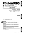
CRAFTSMAN
9HP SNOW THROWER
ENGINE
536.887994
16
2
17
/
2O
22
24
/
18
I0
15
6
11
25-3
\
/8
/
9
Ref. Drive Page
3
Ref. Auger Housing Page
F-0310107L
34
CRAFTSMAN
9HP SNOW THROWER
ENGINE
Key
No.
Part No.
Description
2
143,049001
ENGINE (761611)
3
002x97
BOLT, CARRIAGE
4
028x76
RETAINER, PUSH
5
710026
NUT
6
1501109
PULLEY, ENGINE
7
710247
WASHER
8
71063
WASHER .381D
9
71015
SCREW, 3/6-24Xl.00
10
579932
BELT, V 3L 33.13LG
11
585416
BELT, V 4L 38.1MF16"
12
1501112 YZ
BRACKET ASSEMBLY, IDLER
13
1501065
BUSHING,
14
71060
WASHER, SPLIT
15
910828
SCREW 5/16-24 X 1.00
18
185x164
SPRING, IDLER TRACTION
17
50793
PULLEY, IDLER
18
590
NUT, JAM 3/8-18
20
1501201
GUIDE, BELT
22
71060
WASHER, SPTLK .31X.58X.08
23
1501482
PLATE, ANTI VIBRATION
24
910828
SCREW, 5/16-24X 1.00
25
5-10
IDLER BRACKET
FRAME ASSEMBLY
25-1
1501062E549
PLATE, ENGINE MOUNT
25-2
310169
SCREW, TAP 1/4-20 X .63
25-3
25x020
SCREW, TAP 5/16-18 X .50
25-4
1501049E549
FRAME, MOTOR BOX
25-5
28x263
SCREW
F-0310107L
OWNER'S
--
F-0310107L
536.887994
35
MANUAL
DRIVE
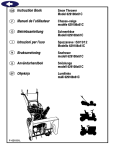
CRAFTSMAN
9HP SNOW THROWER
ELECTRIC STARTER
8
9
7
\
Key No.
F-0310107L
536.887994
Part No.
Description
6
6218
MOTOR, STARTER
7
6216
SCREW
8
6217
SCREW
9
6219
CORD, STARTER
36
CRAFTSMAN
9HP SNOW THROWER
FRAME
536.887994
170
106
1oo
v//
f_---"
162
11_
Ref. Auger
Ref.
Page Engine _
iut
__3
Housing
Page
162_
Ref. Drive
Page
122
103
Key
No.
Pad
90
149
107
Descdption
Key
No.
Pad
1501055E701
COVER, BOTTOM
122
780055
SCREW, TAP
91
310169
SCREW
148
50793
PULLE_IDLER
103
1501226YZ
iDLER, AUGER
149
590
NU_
105
711682
PiN, HAiR
160
1501052
COVER, BELT
106
761761
PiN, CLEVIS
162
26x306
SCREW, TAP
107
165x159
SPRING, TENSION
166
71067
WASHER, FLAT
108
761675YZ
SPRING ATTACH
168
1501200
SPACER
110
585781
BOLT, CARR.
169
760539
LID, TOOLBOX
170
761187
PAD, FOAM
No.
111 711617
F-0310107L
WASHER, FLAT
37
No.
Description
JAM 3_-16
CRAFTSMAN
9HP SNOW THROWER
DRIVE
Ref. Shift Yoke
Page
Ref. Frame
536.887994
_/f-
_
229
2OO
\
225
227
\
/
201
f/
/
/
/
236
204
203
230
220
218
207
215
\
Ref.
Wheel
Page
210
\
208
212
218 217
F-O310107L
/
\
Ref. Whee
Page
206
213
38
238
CRAFTSMAN
F-0310107L
9HP SNOW THROWER
DRIVE
536.887994
Key No.
PaN No.
200
1501092
Description
201
579851
CHAIN, ROLLER #42x19.00
203
334163
BEARING AND RETAINER, ASSY
204
579858
WASHER
206
780055
SCREW, TAP 5/16-18x0.5
207
1501100
ASSY, HEX SHAFT
208
579868
CHAIN, ROLLER #36xl&O0
210
337029
BEARING, TRUNION CLUTCH R
212
1501435
WHEEL,
213
001x38
SCREW, 1/4-20 x 0.63
215
303008
NUT, KEPS HEX 1/4-20
217
579859
RING, RETEXT
218
579858
WASHER
220
334163
BEARING AND RETAINER, ASSY
221
780055
SCREW, TAP 5/16-18 x .5
223
1501115
ASSY, FRICTION PULLEY
225
1501057 YZ
LF PLATE, SWINGING YZ
226
1501158
SPACER, FRICTION PULLEY
227
15X114
NUT, FLANGE LOCK 3/8-24
229
11X30
RETAINER, RING
230
1501107 YZ
LF ASSY, SPRING LINK YZ
232
11X30
RETAINER, RING
234
165X112
SPRING, EXTENSION
236
1501090
WLD, INTERMED SPROCKET
238
71074
WASHER,
YZ
LF AXLE, SWING PLATE YZ
39
LG
FRICTION DISC
FLAT
33T/7
CRAFTSMAN
9HP SNOW THROWER
AUGER HOUSING
536.887994
48O 481
482
527
490
528
522
523
491
\
526 525
493
511
522
\
Ref. Gear
Case Page
5O0
521
524
510
541
\ 527
542 540
F-O310107L
514
40
\
524
520
CRAFTSMAN
F-0310107L
9HP SNOW THROWER
AUGER HOUSING
536.887994
Key No.
Part No.
Description
480
1501211
PULLEY, V4L 8.4X .67
481
577400
SCREW,
482
2001022
KEY, SQUARE 3/16 X 3/4
485
1501158
SPACER, FRICTION PULLEY
490
582957 YZ
RETAINER,
491
43846
BEARING,
493
001X92
BOLT, HEX 5/16-18 X 1/2
499
710026
NUT, 5/16-18 HEXWDFLLK
500
1501185E549
HOUSING,
510
760660E701
BLADE, SCRAPER
511
340720
BOLT, 5/16-18 X 3/4
514
710026
NUT, 5/16-18
520
1501197E701
AUGER, ASSY, LH
521
1501196E701
AUGER, ASSY, RH
522
9524
SCREW
523
3943
SPACER, SLEEVE
524
73826
NUT, 1/4-20
525
9517
BEARING,
526
711862
NUT, 5/16-18
527
9357
SCREW, 5/16-18 X 3/4
540
309016E701
SKID, HEIGHT ADJUST
541
340720
BOLT, 5/16-18 X .75
544
710026
NUT, 5/16-18
550
1501576
BRUSH, CLEANOUT
551
1501672
CLIP, RETAINER
552
06x115
SCREW
553
15x146
NUT
554
578063
BLOCK
--
1501227
KIT, SHEAR BOLT
41
5/16-18X.63
BALL BRNG
BALL
ASSY
FLANGE
CRAFTSMAN
9HP SNOW THROWER
DISCHARGE
CHUTE
536.887994
596
6O0
60O
597
583
600
582
602
603
_
610
601
609
609
606
611
607
\
F-O310107L
42
CRAFTSMAN
Key No.
F-0310107L
9HP SNOW THROWER
DISCHARGE
CHUTE
536.887994
Part No.
Description
582
2X100
BOLT, 5/16-18 X 1.00 CARG.
583
71071
WASHER,
584
15x144
NUT, 5/16-18
596
71071
WASHER
597
1501260
KNOB, WING
599
002x97
BOLT, 5/16-18X1.125
600
762222
CHUTE ASSEMBLY
601
2X100
BOLT
602
71071
WASHER,
603
71038
NUT, 5/16-18 HEXNYL
606
585214 YZ
CHUTE COLLAR
607
02X101
SCREW, 1/4-20 X .75
609
15x145
NUT, 1/4-20 HEX NYLOCK
610
337227
RETAINER RiNG iNNER
611
1501282
RETAINER RING OUTER
43
FLAT
NYLOCK
3.00
FLAT
CRAFTSMAN
9HP SNOW THROWER
GEAR CASE
536.887994
340
3O4
326
324
323
325
\
/
322
/
324
304
301
303
310
\
313
315
320
314
311
303
Key
No.
Pad
Descnption
Key
No.
300
Pad
10577
CASE, GEAR, RH
320
50221
BRNG, FL
301
10576
CASE, GEAR, LH
321
1501191
SHAFT, INPUT
303
710025
SCREW
322
580295
COLLAR,
304
15x143
NUT
323
454565
PIN, SPRING
306
9344
SCREW
324
48275
WASHER,
310
9566
SEAL, OIL
325
50684
BRNG, ROLL
311
50304
BEARING,
326
50304
BRNG, FL
312
48275
WASHER, FLAT
327
9566
SEAL, OIL
313
1501190
SHAF_
340
1501188E701
IMPELLER
314
51279
GASKET
341
454565
PIN, SPRING
315
51405
GEAR, WORM
333431
10oz LUBRIPLATE
316
431787
KE_ WOODRUFF
No.
FL
OUTPUT
No.
Description
THRUST
FLAT
* (NOT ILLUSTRATED)
F-0310107L
44
CRAFTSMAN
9HP SNOW THROWER
SHIFT YOKE
536.887994
796
790
792
801
791
8O0
814
813
802
/
812
Key No.
F-0310107L
Part No.
Description
790
336702E701
ROD, SHIFT
791
302628
SCREW,
792
73826
NUT, 1/4-20
796
331624
KNOB, SLIP
8o0
760564
LEVER, SPRING
801
302628
SCREW,
8o2
73826
NUT, 1/4-20
812
1501085 YZ
ROD ASSY.
813
11X30
RETAINER, RING
814
579944
1/4-20X.75
1/4-20X.75
SPEED SELECT
BEARING, FLANGED
45
CRAFTSMAN
9HP SNOW THROWER
HANDLE
536.887994
731
766
729
734
730
/
734
729
740
741
746
I
756 725
757
758
/
745 f
762
759
745 760
HDL105A
F-O310107L
46
CRAFTSMAN
Key No.
F-0310107L
Pad
9HP SNOW THROWER
HANDLE
No.
536.887994
Description
720
1501205E701
HANDLE, UPPER LH
721
1501206E701
HANDLE, UPPER RH
724
11234
SCREW, 5/16-18X2.75
725
71071
WASHER,
FLAT
726
71060
WASHER,
SPTLK .31X.58X.06
727
15x144
NUT, 5/16-18 REGHEX YZ
728
11261
STOP, RED PLASTIC
729
337399
GRIP-HANDLE
730
337818E701
LEVER, ASSY CLUTCH DRIVE RH
731
337815E701
LEVER, ASSY CLUTCH DRIVE LH
733
337381
ROD, PIVOT CLUTCH
734
761105
NUT, PUSH ON CAP
735
337373
SPACER-HANDLE
739
4049
BUMPER, RECTANGLE
740
1501123
CABLE, CLUTCH
741
761872
CABLE, AUGER CLUTCH
743
313441
BRACKET, CABLE ADJUSTER
744
1673
SPRING, AUGER CLUTCH
745
15x145
NUT, 1/4-20 NYLOCK YZ
746
308146
BOOT, CABLE SPRING
750
339541E701
HANDLE, LOWER
751
25x021
SCREW, TAP 5/16-18 X 0.75
755
337407E701
BRKT, GEAR SELECTOR
756
6751
SCREW, 5/16-18X2.00
757
310169
SCREW, 1/4-20 x 0.63
756
001798
BOLT, HEX 1/4-20 X 1.50
759
579860
SPOOL-CABLE,
760
1501059 YZ
BRACKET, CABLE SPOOL YZ
762
1501122
CABLE, LOWER DRIVE 12"
766
337380
GRIP, CLUTCH HANDLE
47
FINGER
AUGRT CLUTCH
CRAFTSMAN
9HP SNOW THROWER
CHUTE ROD
536.887994
856
855
854
/
855
Ref. Handle Assy
/
!
_
861
\
864
870
852-9
852-5
852-8
852-13
Ref. Auger Housing Assy
/
852-11
852-10
868
852-1
852-2
869
\
\
\
\
/
\
\
/
852-7
/
852-3
F-0310107L
48
CRAFTSMAN
Key No.
F-0310107L
9HP SNOW THROWER
CHUTE ROD
536.887994
Part No.
Description
852-1
1501309 YZ
ASSEMBLY, YOKE & ROD
852-2
313431
WASHER, CURVED SPRING
852-3
1501067
GEAR, CHUTE ROTATION 9T
852-5
579493
PIN, COTTER
852-6
1501306E701
BRACKET, GEAR MOUNT
852-7
1501293
PIN, HAIR
852-8
1501075 YZ
ASSEMBLY, YOKE ADAPTER YZ
852-9
711682
PIN, HAIR
652-10
578060
PIN, UNIVERSAL
852-1 1
578309
PIN, CLEVIS
652-13
578063
HOUSING,
854
51443
KNOB, CRANK
855
309312
FLATWASHER
856
73664
NUT, PUSH
860
581616
EYE BOLT 3/8-16X6.00
861
148
GROMMET,
863
71045
NUT, 3/8-16 HEXJAM
864
71072
FLATWASHER
867
71046
NUT, 3/8-16 HEXNYL
868
002X98
BOLT, CARRIAGE
869
15X145
NUT, 1/4-20 NYLOCK
870
1501074 YZ
CRANK, ASSY CHUTE
49
JOINT
UNIVERSAL
EYE BOLT
.406X.81X.066
1/4-20 X 1.00
YZ
CRAFTSMAN
9HP SNOW THROWER
WHEELS
536.887994
679
678
/
675
671
/
654
650
F_
655
/
652
Re_ Ddve Page
676
655
/
671
673
677
F-0310107L
Key No.
Part No.
Description
650
1501563
SHAFT, AXLE
652
1501089
SPRKT & HUB
653
01x193
SCREW, 1/4-20 x 1.75
654
15X145
NUT. 1/4-20 HEX NYLOCK YZ
655
1501114
BEARING, AXLE
671
712120
WASHER, FLAT
673
1501138
BUSHING,
675
583384
TIRE & RIM -RIGHT
676
577015
SCREW, 1/4-20Xl.75
677
15X145
NUT, 1/4-20 HEX NYLOCK YZ
678
239
RING, RET
679
73842
PIN, KLIK .25 X 1.38 DIA
680
583384
TIRE & RIM -LEFT
50
WHEEL
HH
CRAFTSMAN
9HP SNOW THROWER
PANEL
536.887994
770
771
772
772
Key No.
Part No.
Description
770
1501203E549
PANEL
771
002x99
BOLT, CARRIAGE
772
71067
WASHER
773
15X145
NUT, 1/4-20 NYLOCK
YZ
DECALS
Part No.
Description
48x2034
DECAL
DANGER
48x2036
DECAL
DANGER & FOOT
*
761078
DECAL
DANGER STRIPE
*
48x2038
DECAL
TRACTON/AUGER
48x349
DECAL
SPEED SELECT
760983
DECAL
TOOL BOX - BELT COVER
48x358
NAMEPLATE,
48x389
DECAL, 9/29 CRAFTSMAN
* Not Illustrated
F-O310107L
51
CHUTE - HAND
*
DRIVE - ENGAGE
*
CRAFTSMAN
*
*
*
*
CRAFTSMAN
4-CYCLE
ENGINE
MODEL
NUMBER
143.049001
S7
7O
370C
F-O310107L
52
CRAFTSMAN
KEY
NO,
PART
NO.
4-CYCLE
ENGINE
MODEL
NUMBER
PART
NO.
143.049001
DESCRIPTION
KEY
NO,
RPM High 3550 to 3750
60
33273A
Blower Hsg Extension
DESCRIPTION
RPM Low 2000
65
650128
Screw, 10-24x 1/2"
1
35385
Cylinder (Incl. 2, 20 & 72)
69
37342
Cylinder Cover Gasket
2
3
27652
850820
Dowel Pin
Screw, 1/4-20 x 1/2"
70
35376A
Cylinder Cover
(Incl. 71, 75 & 80)
4
31857
Oil Drain Extension
71
35377
Crankshaft
5
30969
Extension Cap
72
27642
Oil Drain Plug
14
28277
Washer
75
35319
Oil Seal
15
30699C
Governor Rod
(Inc. 1 5A & 1 5B)
60
61
37587
651080
Governor Shaft
Washer
15A
30700
Governor Yoke
62
37588
Governor Gear Ass'y.
15B
850494
Screw, 6-40 x 5/16"
16
33454A
Governor Lever
63
30588A
17
29916
Governor Lever Clamp
64
29193
Retaining Ring
16
851028
Screw, Torx T-15
66
650833
Screw, 1/4-20 x 1-3/16"
bushing
(Incl. 81 )
Governor Spool
19
34663
Speed Control Spring
67
650832
Screw,
20
35319
Oil Seal
69
32589
Flywheel Key
25
37707A
Blower Housing Baffle
90
611093
Flywheel (W/Ring Gear)
26
850561
Screw, 1/4-20 x 5/6"
92
650880
Lock Washer
28
30322
Lock Nut, 8-32
93
650881
Flywheel Nut
30
37231
Crankshaft
100
35135A
Solid State Ignition
35
29826
Screw, 10-32 x 3/4"
101
610118
Spark Plug Cover
36
29918
Lock Washer
102
651024
Solid State Mounting
Stud
37
29216
LockNut,
38
40
29642
40011
Retaining Ring
Piston, Pin & Ring Set
(Std.)
103
110
651007
35187
Screw, Torx T-15
Ground Wire
110A
37047
Ground Wire
40
40012
Piston, Pin & Ring Set
(.010" OS)
119
120
36448
36449
Cylinder Head Gasket
Cylinder Head
41
40009
Piston, Pin Ass'y. (Std.)
(Inck 43)
125
27878A
Exhaust Valve (Std.)
(Incl. 151 )
41
40010
Piston, Pin Ass'y.
(.010" OS) (IncL 43)
125
27880A
Exhaust Valve
( 1/32" OS) (Incl. 151 )
42
40013
Ring Set (Std.)
126
34035
42
40014
Ring Set (.010" OS)
43
27888
Piston Pin Retaining Ring
127
650691
Washer
45
36897
Connecting Rod Assy
(IncL 47 &49)
130
130A
6021A
650727
Screw, 5/16-18 x 1-1/2"
Screw, 5/16-18 x 1-3/4"
47
851033
Connecting
130B
651055
Screw, 5/16-18 x 5/8"
46
34034
Valve Lifter
135
35395
49
36896
Oil Dipper
50
35375
Camshaft
F-0310107L
10-32
1/4-20x 1-11/16"
Intake Valve
(Std.) (IncL 151 )
Rod Bolt
Resistor Spark Plug
(R J1 9LM)
(MCR)
139
53
33369
Governor Gear Bracket
CRAFTSMAN
4-CYCLE
ENGINE
MODEL
NUMBER
30962
143.049001
140
850836
Screw, 10-24 x 1/2"
291
Fuel Line
149
27882
Valve Spring Cap
292
26460
Fuel Line Clamp
149A
35862
Valve Spring Cap
298
650665
Screw, 1/4-15 x 3/4"
150
27881
Valve Spring
300
34186A
151
32581
Valve Spring Keeper
Fuel Tank
(Incl. 292 & 301)
169
27896A
Valve Cover Gasket
301
35355
Fuel Cap
305
35554
Oil Fill Tube
170
28423
Breather Body
171
28424
Breather Element
307
35499
Q" Ring
172
28425
Valve Cover
308
35540
Fill Tube Clip
173
35350
Breather Tube
310
36205
Dipstick
314
650873
Screw, 1/4-20 x 3/4"
315
611111
Alternator Coil (18 Watt)
(Incl, 323)
323
611118
Terminal
325
29443
Wire Clip
327
35392
Starter Plug
328
35593
Ignition Key
329
610973
Terminal
335
36547
Carburetor
336
650765
Screw, 10-32 x 1/2"
338
28942
Screw, 10-32 x 3/8"
340
34154
Fuel Tank Bracket
Terminal
341
34155
Fuel Tank Bracket
342
650561
Screw, 1/4-20 x 5/8"
174
850128
Screw, 10-24 x 1/2"
178
29752
Nut & Lock Washer
182
30088A
Screw, 1/4-28 x 1"
183
34587A
Choke Bracket
184
33263
Gasket
185
33877
Intake Pipe
186
34667
Governor Link
186B
36652
Choke Spring
200
34677
Control Bracket
(Incl. 19,203,294
203
31342
Compression
204
206
851029
810973
& 206)
Spring
Screw, 5-40 x 7/16"
Cover
207
33878
Throttle Link
209
850821
Screw, 10-32 x 1/2"
343
35079A
Bracket, key switch
651060
Screw, 10-23 x 23/64"
Primer Ass'y
215
35440
Control Knob
343A
219
34586
Choke Rod
350
570682A
Choke Knob
351
321800
Primer Line
355
590574
Starter Handle
364
37659
Carburetor
365
650767
Screw, 8-32 x 27/64"
3700
36501
Primer Decal
370G
35077
Control Decal
220
35438
222
28820
Screw, 10-32 x 1/2"
223
850378
Screw, Torx T-30
224
27915A
Intake Pipe Gasket
260
35447A
Blower Housing
Cover Bracket
261
850788
Screw, 5/16-18 x 3/4"
262
851084
Screw, 5/16 24 x 9/16"
3701
37580
Warning Decal
Screw, 1/4-20 x 5/8"
380
640052
Carburetor(Incl.
390
590749
Rewind Starter
264A
850802
184)
265
33272D
Cylinder Head Cover
275
35056
Muffler
396
33329E
Electric Starter (Optional)
400
364500
Gasket Set (]nck items
marked *) Incl. part #'s
27272A, 27896A,
27915A, 29673, 33263,
33629, 34689A, 35262A,
36448
900
756337C
Replacement Short
Block, order from 71-999
276
31588
Locking Plate
277
851002
Screw,
281
33013
Starter Bubble Cover
282
850760
Screw, 8-32 x 3/8"
285
35985B
Starter Cup
287
29752
Nut & Lock Washer
F-O3tOIO7L
5/16-18x4-3/16"
54
CRAFTSMAN
4-CYCLE
12
KEY
NO.
F-0310107L
ENGINE
MODEL
NUMBER
143.049001
13
PART
NO.
DESCRIPTION
0
590749
Rewind Starter
1
590599A
Spring Pin (IncL 4)
2
590600
Washer
3
590679
Retainer
4
590601
Washer
5
590678
Brake Spnng
6
590680
Starter Dog
7
590412
Dog Spring
8
590682
Pulley & Rewind Spring Assembly
11
590750A
Starter Housing Assembly
12
590535
Starter Rope (Length 98" x 9/64" dia.)
13
590574
Mitten Grip Handle(Not included with starter)
55
CRAFTSMAN
4-CYCLE
ENGINE
MODEL
NUMBER
1,,
_o
2
_"
"47
q_-"20
_'_"20A
I
"15
/*
I
I
/ ° ¥.L<::::cC::::_Y _[,.
,TJ.
48 ,-'_'_ I l
29" 0
,)
I
3o
31A'_
28 ...._
1" _::_ 27
0".-.37
l.. o
_41_-....
37
I
I
25
60
44_
40 f t,[_
F-O310107L
56
143.049001
_
CRAFTSMAN
4-CYCLE
KEY
NO.
F-0310107L
ENGINE
MODEL
NUMBER
143.049001
PART
NO.
DESCRIPTION
640052
Carburetor
1
631776A
Throttle Shaft & Lever Assembly
2
631970
Throttle Return Spring
6
631778
Throttle Shutter
7
650506
Shutter Screw
10
632112
Choke Shaft & Lever Assembly
14
632174
Choke Shutter
15
630735
Choke Positioning Spring
16
632164
Fuel Fitting
17
650417
Throttle Crack Screw/Idle Speed Screw
18
630766
Tension Spring
20
640016
Idle Mixture Screw
20A
640053
Idle Restrictor Screw Cap
25
631951
Float Bowl Ass'y. (incl. 32 & 33)
27
631024
Float Shaft
28
632019
Float
29
631028
Float Bowl O Ring
30
631021
Inlet Needle, Seat & Clip (IncL 31)
31
631022
Spring Clip
32
27136A
Bowl Drain Assembly
33
27554
Drain Plunger Gasket
36
640005
Main Nozzle Tube
37
632547
"O" Ring
40
640055
High Speed Bowl Nut
44
27110
Bowl Nut Washer
47
630748
Welch Plug, Idle Mixture Well
48
631027
Welch Plug, Atmospheric
60
632760
Repair Kit
57
(Inc1.184 of Engine Parts List)
Vent
CRAFTSMAN
4-CYCLE
29
\
ENGINE
MODEL
NUMBER
J
23
14---,,-"-16
26
\
10
\7
\6
5A
F-O310107L
143.049001
58
22
CRAFTSMAN
4-CYCLE
KEY
NO.
F-03t0107L
ENGINE
MODEL
NUMBER
PART
NO.
DESCRIPTION
0
33329E
Electric Starter (110 Volt)
1
33451
Dust Cover
2
33842
Retainer Ring
3
33430
Spring Retainer
4
33431
Anti-drift
5A
37050
Gear & Nut (Incl. 2)
6
35449
Drive End Cap Ass'y. (Incl. 7)
7
35450
"O" Ring
8
35915
Armature
9
35451B
Housing Ass'y.
10
35452A
Brush Card Ass'y.
11
35911
Thrust Washer
13
590500
Thrust Washer
14
33441
Ground Screw
15
35453
Commutator
Spring
End Cap Ass'y. (Incl. 7)
16
35454
Switch Box Ass'y.
22
35455
Case Bolt
23
35456
Ground Screw
26
650819
Screw, 6-32 X 2-1/2"
29
32450B
Extension Cord (10'6")
30
30063
Screw, Torx T-30, 1/4-20 X 1/2"
31
650820
Screw, 1/4-20 X 1/2"
59
143.049001
NOTES
F-O310107L
60
[i[o] 11d11II,]{o]
PLEAS DE REPUEST0 ............
PLEAS DE REPUEST0- MOTOR ....
GARANTIA .....................
REGLASDE SEGURIDAD ..........
SIMBOLOSINTERNACIONALES.....
34
52
61
61
64
ENSAMBLAJE...................
66
GARANTIA
OPERACI(_N....................
MANTENIMIENTO ................
SERVICIOYAJUSTES .............
ALMACENAMIENTO ..............
TABLADE LOCAUZACI(_NY
REPARACI(_NDEAVERIAS .....
PEDIDODE PIEZAS/SERVICIO.......
LIMITADA DE DOS AltOS PAPA EL QUITANIEVES
70
76
79
89
90
96
CRAFTSMAN
Durante dos aSos a partir de la fecha de compra, siempre que a este quitanieves Craftsman se le
d6 mantenimiento, lubricaci6n y afinamiento de acuerdo con las instrucciones de operaci6n y mantenimiento presentadas en el manual del usuario, Sears reparar&, sin cargo alguno, cualquier defecto en material y mano de obra.
Si este quitanieves Craftsman es usado con prop6sitos comerciales o de arrendamiento, esta garantia ser_ v_lida solamente por 90 dfas a partir de la fecha de compra.
Esta garantia no cubre Io siguiente:
Elementos de desgaste normal, tales como bujfas, correas de transmisi6n y pasadores de seguridad.
Reparaciones necesarias debido al abuso o negligencia del operador, incluyende variltas deblados y otras reparaciones necesarias por falta del mantenimiento a la unidad seg_n Io recomendado en las instrucciones contenidas en el manual del propietario.
EL SERVICIO DE GARANT|A SE PUEDE OBTENER LLEVANDO EL QUITANIEVES AL CENTRO DE SERVICIO SEARS MAS CERCANO EN LOS ESTADOS UNIDOS. ESTA GARANT|A ES
VALIDA SOLO CUANDO ESTE PRODUCTO ES USADO EN LOS ESTADOS UNIDOS.
Esta garantia le otorga derechos legales especificos, y asimismo es posible que tenga otros derechos los cuales varian de un estado a otto.
Sears, Roebuck and Co., D817WA, Hoffman Estates, IL 60179
I-'tl[e']_._. I11!]!!.1![_1 J-'II=7.'I=]
Preste atenci6n a e.ste slmbolo, le indica precauciones de seguridad importantes.
nifica-iiiA
TENCION!!! iiiESTE ALERTA!!! Se trata de su seguridad.
Sig-
Siempre
desconecte
DVERTENCIA:
el cable de la bujia y
colbquelo
alejado de _sta
para prevenir un arranque
accidental durante la preparacibn mantenimiento
o almacenamiento
del quitanieves.
_
Las emanaciones de escape producidas por este
motor y ciertos componentes de esta m&quina contienen quJmicos reconocidos pot el Estado de California como carcinbgenos, tambi_n pueden producir defectos en los reci_n nacidos o causar otros da_os al sietema reproductivo.
LOS bornes, terminalee y acceeorios relacionados
con la bateria contienen plomo y compuestos del
plomo, adem&s de sustancias quimicas que el Estado de California reconoce que estos compuestos
pueden causar cbncer y defectos como carcinbgenae, adembs eetae sustanciae pueden producir da£zos cong_nitos, a los beb_s y adembs de otros da£zos al sistema reproductivo humano. DEBE LAVARSE MUY BIEN LAS MANOS DESPUES DE MANIPULAR ESTOS COMPONENTES.
F-03t0107L
61
IMPORTANTE:
Para prevenir
lesiones, las normas de seguridad exigen controles en la unidad
que s61o puedan ser manejados
en presencia del operador. Su
quitanieves est_ equipado con
dichos controles. Por ningt_n motivo intente pasar por alto la funci6n del control en presencia del
operador.
CAPACITACION
1.
Lea con atenci6n las instrucciones
y/o del sol hace que el combustible
se expanda.
en el
manual de operaci6n y servicio. Familiaricese completamente con los controles y
el uso apropiado del quitanieves. Aprendaa detener el quitanieves y a desen*
ganchar r_pidamente los controles.
5.
2.
Nunca permita a niSos operar el quitanieves. Nunca permita que adultos ope*
ten el quitanieves sin la instrucci6n
apropiada.
3.
Mantenga el Area ]ibre de personas, especialmente niSos pequeSos y mascotas.
7.
4.
Tenga mucho cuidado para evitar resbaIones o caldas, especialmente cuando
est6 retrocediendo.
8.
6.
PREPARACI6N
1.
Inspeccione completamente el Area donde se usar_ el quitanieves y retire todas
las esteras, trineos, tableros, cables, y
otros objetos extraSos.
2.
Desenganche todos los embragues antes
de hacer arrancar el motor.
3.
No opere el quitanieves sin vestir prendas de inviemo adecuadas para trabajar
a la intemperie. Vista calzado que le d_
buena tracci6n sobre superficies resbalosas.
4.
OPERACION
1.
2.
3.
Maneje el combustible con cuidado; 6ste
es altamente inflamable.
(a) Use un contenedor
combustible.
aprobado para
4.
(b) Nunca quite la tapa del tanque de
combustible ni a5ada combustible a
un motor en marcha o a un motor caliente.
(c) Llene el tanque de combustible al aire libre y con mucho cuidado. Nunca
Ilene el tanque en un recinto cerrado.
(d) Vuelva a colocar la tapa del tanque
de combustible de manera segura, y
limpie el combustible derramado.
(e) Nunca almacene combustible o el
quitanieves con combustible en el
tanque dentro de un edificio donde
los vapores pudiesen alcanzar alguna llama abierta o chispas.
(f)
Para todos los quitanieves con motores
de arranque el6ctrico, use cables de extensi6n con certificaci6n CSA/UL Use
solamente tomacordentes que hayan sk
do instalados de acuerdo con los reglamentos de inspecci6n locales.
Jam_s intente efectuar ningtin ajuste
mientras el motor se encuentra en marcha (excepto cuando el fabricante Io recomiende asf especlficamente).
Permita que el motor y el quitanieves se
ajusten alas temperaturas exteriores antes de comenzar a despejar la nieve.
Siempre use gafas de seguridad o protectores para los ojos durante la operaci6n o mientras efectQa algt_n ajuste o
reparaci6n a la unidad, para proteger sus
ojos de objetos extraSos que pudiesen
ser lanzados pot el quitanieves.
No opere este quitanieves siesta toman*
do medicinas que puedan causar somnolencia o afectar su habilidad para operar
el quitanieves.
No use el quitanieves
si por motivos
emocionales o fisicos se le dificulta manejarlo de forma segura.
No coloque las manos o los pies cerca o
debajo de piezas en movimiento. Mant6ngase en todo momento a buena distancia de la abertura del tubo de
descarga.
Tenga mucho cuidado al operar el quitanieves en o a trav6s de entradas de autos, senderos o caminos de grava.
Mant6ngase alerta de peligros ocultos o
tr_fico.
5..
Si golpea un objeto extraCto, pare el motor, desconecte el cable de la bujia, inspeccione meticulosamente el quitanieves
por si hubiera algt_n da5o, y rep&relo antes de arrancar el motor y operar el quitanieves nuevamente.
6.
Si el quitanieves comienza a vibrar de
manera excesiva, pare el motor y reviseIo inmediatamente para encontrar la causa. Generalmente, la vibraci6n es una
advertencia de alg0n problema.
Pare el motor cuando deje la posici6n de
operaci6n, antes de desobstruir el alojamiento de la barrena/propulsor o el tubo
de descarga, y cuando efectQe cualquier
reparaci6n, ajuste o inspecci6n.
Cuando limpie, repare o inspeccione el
quitanieves, asegt3rese de que la barre-
7.
Verifique que el quitanieves tenga
suficiente combustible antes de cada
use, y deje un espacio adicional en el
8.
tanque puesto que el calor del motor
F-0310107L
62
na/propulsor
ytodas
laspartes
m6viles
seencuentren
detenidas,
yquetodos
los
controles
est6n desenganchados. Desconecte el cable de la bajia y mant_ngalo
alejado de ]a bujia para evitar un arranque accidental.
9.
Tome todas las precauciones posibles al
dejar el quitanieves desatendido. Desenganche la barrena/propulsor, pare el motor y retire la Ilave.
10. No haga arrancar el motor en recintos
cerrados, excepto para arrancar y para
transportar el quitanieves hacia adentro o
hacia afuera del recinto. Abra las puertas
que dan al exterior; los vapores de escape son peligrosos (contienen MONOXIDO DE CARBONO, un GAS INODORO y
LETAL).
ruedas, juegos de arranque el6ctrico,
etc.).
19. Nunca opere el quitanieves sin tener buena visibilidad o ilaminaci6n. Asegerese
siempre que tiene buena estabilidad, y
sajete con firmeza el mango. Camine;
nunca aorta.
20. No trate de alcanzar _reas diffciles. Mantenga la estabilidad y el balance en todo
memento.
21. No trate de usar el quitanieves
piar techos.
MANTENIMIENTO Y
ALMACENAMIENTO
11. No use el quitanieves para limpiar _reas
de terreno inclinadas (cuestas, pendientes). Tenga mucho cuidado cuando cambie de direcci6n. No intente limpiar
pendientes muy pronunciadas.
1.
Revise los pernos con frecuencia para
asegurar que est6n bien apretados y que
el quitanieves est6 en condicionea segaras de funcionamiento.
2.
Nunca guarde el quitanieves con combustible en el tanqae dentro de un recinto
donde hubieran fuentes de ignici6n tales
como calentadores de agua y estufaa,
secadoras de ropa, y similares. Permita
que el motor se enfrie antes de guardar
el quitanieves en caalqaier recinto.
3.
Siva a almacenar el quitanieves por un
periodo prolongado, siempre consulte las
instrucciones del manual del operador
donde encontrara consejos importantes.
4.
Mantenga o reemplace laa etiqaetas de
seguridad e instrucciones, segQn sea necesario.
5.
Mantenga el quitanieves en marcha unos
cuantos minutes despu6s de despejar la
nieve, para evitar qae se congele la barrena/propulsor.
12. Nunca opere el quitanieves sin que los
resguardos, placas u otros dispositivos
de seguridad se encuentren en su lugar.
13. Nunca opere el quitanieves cerca de escaparates de vidrio, autom6viles, vidrieras, sitios de carga/descarga, y similares,
sin el ajuste apropiado del angulo de descarga de la nieve. Mantenga a los niSos y
las mascotas alejados del _rea que est_
despejando.
14. No sobrecargue la capacidad del quitanieves al intentar limpiar la nieve a una
velocidad demasiado r_pida.
15. Nunca opere el quitanieves a a]tas velocidades de transporte sobre superficies
resbalosas. Mire hacia atr_s y tenga cuidado al retroceder.
es
para uso en aceras,
entradas
ADVERTENCIA:
Este quitanieves
de auto y otras superficies de terreno planas. Se debe tenet cuidado al
usar el quitanieves en superficies inclinadas. NO USE EL QUITANIEVES
EN SUPERFICIES SOBRE EL NIVEL DEL SUELO
_lb
16. Nunca descargue directamente hacia espectadores ni permita a nadie frente al
quitanieves.
17. Desenganche la fuerza motriz de la barrena/propulsor cuando el quitanieves
sea trasportado o no est6 en uso.
tales como techos de residencias, de garajes, porches u otras estructuras o construcciones aimilares.
18. Utilice 8nicamente aditamentos y accesorios aprobados por el fabricante del quitanieves (tales como cadenas para ]as
F-0310107L
para ]im-
63
IMPORTANTE: Muchos de estos simbolos est_n colocados en su quitanieves o estan impresos en
los manuales que vienen con el producto. Antes de operar el quitanieves aprenda y comprenda el
objetivo de carla simbolo,
Simbolos de control y operacibn
Despacio
R_pido
Arranque eldctrico
@ @ o
Motoren
marcha
Motor
apagado
Apagado
I',I H
Ahogador
desactivado
Arranque de motor
I
Encendido
N
Ahogador
activado
Neutro
Acelerador
® G
Botbn cebador
Embrague
de propulsibn
Colector
de barrena
F-0310107L
Ignicibn
desactivada
Llave de encendido
Avance
Marcha atr_s
Enganchar
Optima para accionar
el arranque el_ctrico.
64
Ignicibn
activada
Embragoe
de barrena
0
Transmisibn
Simbolos de control y operacibn
Combustible
Descarga hacia
ABAJO
Mezcla de combustible
y aceite
Aceite
Descarga hacia
ARRIBA
Descsrga hacis |s
IZQUIERDA
Descar s hscia |a
DE_ECHA
[]m
Transferencia de peso
Levante el mango
pars enganchar,
Transferencia de peso
Presione et peda|
para desenganchar.
Llave de encendido
Insertsr pars marcha,
Retirar pars parar=
Simbolos de advertencia de seguridad
A
m4
PELIGRO
Objetos lanzados.
Mantenga alejsdos a
los trsnse_ntes.
PELIGRO
Objetos lanzados.
Mantsnga alejsdos a
|os transe_tntes.
IMPORTANTE
Lea el manual del
propietario antes de
opersr esta maquina.
PELIGRO
Evite las lesiones que puede
causar la barrena rotatoria.
Msntenga Iss manos, los pies y
la ropa fuers de su alcance.
ADVERTENCIA
Superficie csliente
F-O310107L
PARE
65
ADVERTENCIA
m
PELIGRO
Pare el motor
antes de desatascar
el tubo de descarga.
CONTENIDO
DE LA BOLSA DE PARTES (TAMANO REAL)
1 - Manual det Propietario (no se muestra)
1 - Paquete de estabiiizador de combustible (no se muestra)
1 - Tarjeta de garantia (no se muestra)
*Las partes que no necesitan ensamblado se encuentran en la caja de herramientas ubicada en la
cubierta de la correa,
PARTES QUE VIENEN EMPAQUETADAS EN FORMA SEPARADA
DE CARTON (NO SE MUESTRAN EN SU TAMAI_IO REAL)
2- Llaves de ignici6n (Adjuntas a
motor en bolsa pl_stica)
F-0310107L
66
EN LA CAJA
La Figura 38 muestra el quitanieves
completamente ensamblado.
La referencia a los lados izquierdo y
derecho del quitanieves se hace desde
la posiciSn del operador cuando 6ste se
encuentra detr_s de la unidad.
gafas
de seguridad
o protectoDVERTENCIA:
Siempre
use
res para los ojos mientras ensambla el quitanieves.
_lb
HERRAMIENTAS
NECESARIAS
1 - Cuchillo para cortar la caja
2 - Llave de tuercas de 1/2 pig
(o Ilave de tuercas ajustable)
2 - Llave de tuercas de 9/16 pig
(o Ilave de tuercas ajustable)
2 - Llave de tuercas de 3/4 pig
(o Ilave de tuercas ajustable)
1 - Alicate (para abrir las patas
del pasador de chaveta)
1 - Destornillador
Palanca de propulsi6n
de la barrena
Palanca
de cambio_
Palanca de
per tracci6n
Cable del
embrague
Manivela
1 - Cinta o regla para medir
Patines de
ajuste de
altura
Figura 37
La Figura 37 muestra el quitanieves en
posici6n de env[o.
Tomillo
C6MO
SACAR EL QUITANIEVES
DE LA CAJA
1. Ubique todas las piezas que vienen
empaquetadas por separado y
s_quelas de la caja.
NOTA: Coloque el estabilizador de
el tornillo que sujeta cada patina
]a plataforma. Yea la Figura 38.
5. Agarre el quitanieves por el mango
y jale para sacado de la plataforma.
PRECAUCl6N:
NO retroceda sobre los cables de control.
6. Quite el material de empaque del
combustible en un lugar seguro
hasta que Io necesite para guardar
]a unidad.
2. Quite y deseche el material de
empaque que rodea la unidad.
3. Haga un corte de arriba hacia abajo
en cada esquina de la caja y deje
los paneles sobre el suelo.
4. Para propSsitos de envio, los patines de ajuste de altura, van sujetos a la plataforma de envio. Saque
F-0310107L
Figura 38
7.
67
conjunto de los mangos.
Corte los amarres que sujetan el
cable de control del embrague al
mango inferior, y col6quelo alejados
del bastidor del motor.
C6MO ENSAMBLAR EL MANGO Y
EL CONJUNTO DE LA MANIVELA
Conexi6n en "Z"
1. Corte los amarres que sujetan la
palanca de cambios al mango
inferior y mueva la palanca a la
primera velocidad de avance.
2.
Corte y deseche el amarre de pl_stico que sujeta el conjunto de la manivela.
Cable de control
3. Afloje pero no quite los tornillos,
arandelas planas, arandelas de
seguridad y tuercas hexagonales
que se encuentran en los agujeros
superiores del mango inferior. Vea
la Figura 39.
4.
Figura 40
6,
Instale los sujetadores que quit6 en
el paso 4. NO los apriete hasta
tener todos los )ernos en su lugar,
Lade izquierdo del \
mango superio_'_.
Retire los sujetadores y el perno de
anilla de los agujeros inferiores del
mango inferior. Vea la Figura 41.
Manivela
mango superior
n_i_u _lreCa
Perno
de anilla
Afloje pero
no quite
Arandela
7.
Conecte el eje de la manivela a la
junta universal con el pasador de
horquilla. Vea la Figura 42.
8. Apriete la tuerca del perno de
anilla. AsegDrese de que el pemo
de anilla est6 bien alineado y que
la manivela pueda girar libremente.
9. Apriete todos los pemos del mango.
Tuerca
5/16 pig
• Tornillo de
5/16 pig
Arandela de segurid
dad (ab erta) de
5/16 pig
Arandela
Figura 41
Figura 39
NOTA: Asegt_rese de que los
cables no queden atrapados entre
los mangos superior e inferior.
5,
Levante el mango superior a la
posici6n de operaci6n.
NOTA: Si los cables se hart desconectado, con6ctelos como se muestra en la
Figura 40.
F-0310107L
Junta universal
Figura 42
68
Cable de
propulsi6n
NOTA: Si los cables se han desconectado, con6ctelos como se muestra en la
Figura 43.
Cable de propulsi6n de la barrena
Figura 43
COMO AJUSTAR LOS PATINES DE ALTURA
Su quitanieves esta equipado con patines de
ajuste de altura ubicados en la parte exterior
del alojamiento de la barrena. Para ajustar
los patines de altura para diferentes condi-
C(3MO ESTABLECER
clones, consulte "Ajuste de los patines de
altura", en la secci6n de Servicio y Ajustes.
LA LONGITUD DE LOS CABLES
Puesto que los cables fueron ajustados en ]a
f_brica, no es necesario que usted los ajuste. Sin embargo, una vez que se instalan los
mangos en la posici6n de operaci6n, es posible que los cables queden muy tirantes o
muy flojos. Si es necesario ajustados, consuite el parrafo "C6mo revisar y ajustar los
cables" que aparece en la secci6n de Servicioy Ajustes.
_-" MSTA DE REVISION
Antes de usar su nuevo quitanieves, y para
asegurar que obtenga el mejor rendimiento y
la mayor satisfacci6n de este producto de
calidad, por favor haga un repaso de la siguiente lista de revisi6n:
AI mismo tiempo que aprende a usar su quitanieves, preste mucha atenci6n a los importantes detalles a continuaci6n:
,..," El aceite del motor est_ al nivel adecuado.
,..," Asegtirese que el tanque de gasolina est_
Ileno con gasolina limpia, fresca y sin plomo.
_' Familiaricese con todos los controles, su
ubicaci6n y funci6n. Opere los controles
antes de hacer arrancar el motor.
_"
Se han completado todas las instrucciones de ensamblado.
,..," El canal de descarga gira libremente.
,..," No quedan piezas sueltas en la caja de
cart6n.
,..," Revise los sujetadores. Compruebe que
todos est6n bien apretados.
_" En los modelos de arranque el_ctfico, la
unidad ha sido enviada con el cable del
sistema de arranque enchufado al motor.
Antes de utilizar la unidad, sirvase desenchufar el cable de arranque del motor.
F-O3tOIO7L
69
CONOZCA
SU QUITANIEVES
LEA ESTE MANUAL DEL USUARIO Y LAS REGLAS DE SEGURIDAD ANTES DE USAR
USAR SU QUITANIEVES. Compare las flguras con su QUITANIEVES para familarizaree con
las posiciones de los diversos controles y ajustes. Guarde este manual para referencia futura.
Palanca de
Bot6n de arranque el_ctrico
de la barrena
,
(mano derecha)
Bot6n cebador
Caja delto-
Palanca de propulsi6n pot tracci6n
(mano izquierda)
Llave de
Manivela
Deflector de
descarga
Canalde
Estrangulado[
Control de
aceleraci6n
Tanque de
combustible
Manija de arranque
manual
Patines de ajuste de aflura _--
Palanca de propulsibn de la barrena Arranca y detiene la barrena y el propulsor
(recoge y lanza la nieve).
Llave de ignicibn - Debe set insertada para
arrancar el motor.
Manija de arranque manual - Para arrancar
el motor de forma manual.
Palanca de propulsibn pot traccibn - Impulsa el quitanieves hacia delante o hacia
arras.
Estrangulador.
motor frio.
Palanca de cambio de velocidades - Selecciona la velocidad del quitanieves (6 velocidades hacia adelante y 2 velocidades hacia
arras).
Se usa para arrancar un
Botbn cabador - Injecta combustible direc_amente dentro del carburador o distribuidor para an arranque r_pido en temperatures bajas.
Control de aceleracibn - Controla la velocidad del motor.
Manivela - Cambia la direcci6n de lanzamiento de la nieve.
Botbn de arranque el_ctrico (si la unided Io
tiene) - Se usa para arrancar el motor usando el arrancador el6ctrico de 120V.
Deflector del canal de descarga -Cambia la
distancia de lanzamiento de la nieve.
Pasadores de seguridad - Pemos diseSados especialmente para romperse (para proteger la mbquina) si un ebjeto se atasca en el
alojamiento de la barren&
Canal de descarga - Cambia la altura de
]anzamiento de la nieve,
Pa_ines de ajuste de a_ura - Ajustan la distancia libre entre el te_eno y el al_amiento de
]aba_ena.
F-0310107L
Pasadores de
seguridad
Barra raspadora
Figura 44
70
Caja de herramientas - Contiene pasadores
de seguridad y espaciadores de repuesto.
Laoperaci6n
decaalquier
quitanieves
puede
ocasionar
queobjetos
extraSos
sean
lanzadosconfuerza
hacia
losojos,Iocualpodrfa
resultar
enlesiones
graves.
Usesiempre
gafas
deseguridad
oprotectores
para
los
ojosmientras
opera
elquitanieves.
Serecomiendan
lasgalas
deseguridad
est_ndar
olam_scara
deseguridad
devisi6n
amplia
para
usarla
sobre
losanteojos.
del propietario antes de operar
ADVERTENCIA: Lea el manual
la mbquina. Nunca dirija la des=
carga hacia los transe_ntes. Pare el motor antes de desobstruir el canal de descarga o el alojamiento de la barrena y antes de dejar la mdquina.
ca de cambio de velocidades a la ranura
apropiada del panel de control de cambios.
2. Para detener las ruedas, suelte la palanca de propulsibn por traccibn.
3. Para parar el motor,empuje la palanca
de control de aceleracibn a la pesici6n
APAGADO y saque la Ilave de ignicibn.
C(_MO CONTROLAR LA DESCARGA DE
NIEVE
1. Gire la manivela de control para establecer
la direc.dlSn del lanzamiento de la nieve.
2. Afloje la tuerca de mariposa en el deflector del canal de descarga y ajuste el
deflector para establecer la distancia.
Mueva el deflector hacia (ARRIBA) para
mayor distancia, hacia (ABAJO) para
una distancia menor. Luego apriete la
tuerca de mariposa
(Figara 45).
3 - Nieve ligera
Velocidad 5, 6 - Para transportar
dad solamente
]a uni-
2.
Enganche la palanca de propulsi6n per
tracci6n (mano izquierda). A medida
que el quitanieves comienza a moverse,
sajete firmemente los mangos, y gale el
quitanieves a Io largo de] camino a despejar. No intente empajarlo.
3.
Para mover el quitanieves en retroceso,
mueva la palanca de cambio de velocidades a la primera o segunda velocidad de
retroceso y enganche la palanca de propulsi6n por tracci6n (mano izquierda).
EL QUITANIEVES
1. Para detener el lanzamiento de nieve,
suelte la palanca de propulsibn de la
barrena.
1, 2 - Nieve mojada, pesada
Velocidad
Velocidad 4 - Nieve may ligera
_
C(_MODETENER
Velocidad
IMPORTANTE: Nunca mueva la palanca de
cambio de velocidades mientras la palanca
de propulsibn por traccibn estb abajo.
LANZAMIENTODE NIEVE
1. Empuje la palanca de propulsi6n de la
barrena (mano derecha) hacia abajo.
2. Su61tela para detener el lanzamiento
nieve.
de
C(_MOUSARELPASADORDE
ENGANCHEDELA RUEDA
1. La rueda del derecho va asegurada al eje
por medio de un pasador de enganche
(pasador klick). Esta unidad fue despachada con el pasador en la posioibn de
enganche (a trav6s del agajero de la
rueda). Figura 46.
Pasador klick
Tuerca de mar
'Figura 45
Posici6n de
enganche
C(_MOAVANZARY RETROCEDER
1. Para cambiar de velocidad, suelte la palanca de propulsi6n por tracci6n (mano
izquierda) y mueva la palanca de cambios a la velocidad deseada. La velocidad en el terreno ser_ determinada por
las condiciones de la nieve. Seleccione la
velocidad que desea moviendo la palanF-03t0107L
71
Tracci6n en
2 ruedas
Figura 46
2.
Para facilitar la maniobra de la unidad en
condiciones de nieve ligera, desconecte
el pasador klick de la posicibn de enganche de la rueda e introd_zcalo en el
agujero para tracci6n de una rueda (desenganche solamente el agujero-del
eje). Figura 47.
J
Figura 47
NOTA: El nivel del aceite deber_ estar
entre la marca FULL (lleno) y la marca
NOTA: AsegOrese de que el pasador klick
est6 en la posici6n de tracci6n de una sola
rueda en el eje solamente, y no est6 insertado a tray,s de la posici6n de enganche.
ADD (agregar)
Figura 48
4. Apriete flrmemente la tapa/varilla cada
vez que revise el nivel de aceite.
ANTESDE ENCENDEREL MOTOR
NOTA: En Areas donde la temperatura se
mantiene constante en los -6,7°C (20°F) o
menos, puede usar aceite del tipo S.A.E.
5W-30 pare facilitar el encendido de] motor.
1. Antes de dar servicio o encender el motor, familiadcese con su quitanieves. AsegQrese de conocer la ubicaciSn de todos
los controles y entender su funci6n.
COMBUSTIBLE
2. Revise la tensidn del cable del embrague
antes de arrancar el motor. Consulte el
Ajuete del cable de control que aparece en la secci6n de Servicio y Ajustes
de este manual.
La certificaci6n del motor indica que _ste
cumple con las estipulaciones de las normas
de regulaci6n de emisiones de California y
de la US EPA para motores ULGE (en equipo de servicio opara prados y jardines). Los
motores ULGE est_n certificados para funcionar con gasolina regular sin plomo.
3. Aseg_rese de que todos los sujetadores
est_n apretados.
4. Compruebe que el ajuste de los patines
de altura est_ correcto. Consulte el parrafo "Ajuste de los patines de altura" que
aparece en la secci6n de Servicio y
Ajustes de este manual,
bles mezclados con alcohol
DVERTENCIA:
Los combusti(llemados gasohol o aquellos
que usen etanol o metanol) pueden
atreer hurnedad le cuel conduce e la se_IL
5. Revise la presi6n de los neumaticos
(14-17 libres). No exceda el limite maximo de presi6n.
parecibn y formacibn de _cidos durante
el elmacenemiento.
Los gases ecidicos
pueden defiar el sistema de combustible
de un motor mientras se encuentra en
almecenamiento.
REVISION AR DEL ACEITE:ANTES DE
ARRANCAR EL MOTOR
NOTA:El motor rue enviado de la f_bdca
conaceite. Revise el nivel de aceite.Afiada
aceite seg_n sea necesario,
NOTA: Para evitar problemas en el motor, el
sistema de combustible debe vaciarse antes
del guardar la unidad por 30 dias o m&s.
Arranque el motor y d6jelo en marcha hasta
que las llneas de combustible y el carburadot est6n vacios. Use gasolina fresca la siguiente temporada. Para mayor informaci6n
consulte la secci6n de Almacenamiento de
este manual.
Paraa_adiraceite
1. AsegQrese de que la unidad se encuentre sobre una superficie nivelada.
NOTA: No revise el nivel de aceite estando el motor en marcha.
2. Quite la tapa/varilla indicadora del nivel
de aceite. Revise el nivel.
Nunca use productos de ]impieza de motor o
carburador en el tanque de combustible, de
Io contrario podria causar dafio permanente
ala unidad.
3. Si es necesario, afiada aceite hasta la
linea FULL (lleno) en la tapa/varilla indicadora del nivel de aceite (Figura 48).
No exceda ]a medida.
F-03t0107L
Tapa/varilla indicadora
72
Llene
eltanque
solamente
congasolina
fres*
ca,limp]a,
regular
sinplomo,
sQper
sinplomoogasolina
automotor
reformulada.
NO
usegasolina
conplomo.
Asegt_rese
deque
el recipiente que contiene la gasolina a utilizar, est6 Iimpio y sin 6xido u otras partlculas
extra£Las. Nunca use gasolina que pueda
estar vencida debido a su prolongado almacenamiento.
arranque estb equipado con un
DVERTENCIA: El motor de
cable de alimentacibn y enchufe trifilar, dise_ados para funcionar con
corriente dom_stica de 120 voltios CA. El
cable de alimentacibn deberb estar co_IL
nectado a tierra en todo momento para
evitar la posibilidad de un choque el_ctrico que podria lesionar al operador.
Siga cuidadosamente todas las instrucciones de la seccibn "Arranque
del motor."
inflamable y debe tenet mucho
DVERTENCIA: La gasolina es
cuidado al manipularla o
alamcenarla.
_i
•
No Ilene el tanque de combustible
mientrae el quitanievea ee encuentre
en marcha, cuando estd caliente, o
cuando el quitanieves
en un &rea cerrada.
•
•
Verifique que el alembrado el_ctrico
de su casa tenga un sistema trifilar
conectado a tierra. Si no estb seguro
de esto, pregt_ntele a un electricista
profesionaL Si su casa no cuenta con
un sistema de alambrado el_ctrico trifilar, no use el arrencador el_ctrico
se encuentre
bajo ninguna circunstancia.
Si su sistema est_ conectado a tierre
Mantenga la unidad alejada de llamas
abiertas o chispas el_ctricas y no fume mientras Ilena el tanque de combustible.
pete no dispone de un tomacorrientes
trifilar, en on punto conveniente para
enchufar su arrancador el_ctrico, pida
a un electricista profesional que le
instale uno.
Nunca Ilene eltanque completamente,
Llene el tanque haeta dejar entre
1/4-1/2 pulgada de la parte superior
para proporcionar espacio para la expansibn del combustible.
•
Siempre Ilene el tanque el aire libre y
use un embudo o boquilla para prevenit el derrame.
•
Asegt_rese de limpiar cualquier combustible derramado antes de arrancar
el motor.
•
Almacene la gasolina en un contendot, limpio y aprobado, y mantenga la
tapa puesta y segura en el
corltenedor.
PARADADEL MOTOR
Para parar la marcha del motor, mueva la
palanca de control de aceleraci6n a la posici6n PARAR y retire la Ilave. Mantenga la
Ilave en un ]ugar seguro. El motor no puede
arrancar sin la Have de ignici6n.
Para conectar el cable de alimentacibn de 120 voltios de CA, siempre
conecte primero el cable a la caje del
tomacorrientes del motor, luego enchufe el otto extremo en el tomacorrientes trifiler coneetado a tierra. AI
desconectar el cable de alimentacibn
el_ctrica, siempre desenchufe primero el extremo en el tomacorrientes conectado a tierra.
C6mo hacerarrancarel motoren fr|o
1. Compruebe que las palancas de propulsi6n de la barrena y de propuisi6n por
tracci6n est6n en la posici6n desenganchado.
2.
Mueva el control de aceleraci6n
ci6n "RAPIDO'.
3.
Inserte la Ilave en ia ranura de ignici6n.
AsegQrese de que al meter la Ilave oye
que 6sta hace un sonido de enganche.
No gire la Ilave.
4.
Gire la perilla del estrangulador hacia la
derecha a la posici6n "ACTIVADO".
5.
(Arranque el_etrico) Conecte el cable
de alimentaci6n a la caja del tomacorrientes en el motor. Enchufe el otro ex*
tremo del cable de alimentaci6n en un
ARRANOUEDELMOTOR
Aseg_rese de que e] motor tenga suficiente
aceite. El motor del quitanieves esta equipado con un arrancador el6ctrico de 120 voltios
de corriente altema y con un arrancador manual. Antes de arrancar el motor, asegt_rese
de haber leldo la informaci6n siguiente:
F-0310107L
73
a la posi-
tomacorrientes
trifilar
de120voltios
CA,
conectado
atierra.
6. Empuje
elbotbn cebador de la manera
indicada a continuaci6n. Quite el dedo
del bot6n cebador entre cebados.
No use la funci6n de cebado si la temperatura est_ sobre 50 ° F (10 ° C).
•
Optima el bot6n dos veces si la temperatura esta entre 50 ° F (10 ° C) y
15 ° F (-10 ° C).
•
Oprima el bot6n cuatro veces si ]a
temperatura se encuentra por debajo
delos 15 ° F (-10 ° C).
•
Optima el bot6n cinco veces si ]a temperature se encuentra por debajo de
los 0 ° F (-18 ° C).
7. (Arranque el#ctrico) Presione el botbn
de arranque hasta encender el motor.
No Io presione por mas de 10 segundos
ala vez. Este motor de arranque el6ctrico cuenta con protecci6n t_rmica. Si se
sobrecalienta se detendr& autom_ticamente y puede set arrancado nuevamente s61o cuando se haya enfriado a una
temperatura segura (debe esperar entre
5 y 10 minutos aproximadamente).
8. (Arranque a manual) Jale rapidamente
la manija del arranque manual. No
suelte la manije inmediatamente despu6s de jalarla. Deje que la manija del
arranque manual se enrolie lentamente.
C6mo hacerarrancarun motorcaliente
Siesta arrancando un motor caliente despu6s de haberlo apagado por un periodo
corto, deje la palanca del estrangulador en ]a
posici6n "DESACTIVADO" y no oprima el
bot6n cebador. Si el motor no arranca, siga
]as instrucciones sobre Arranque del motor
en frfo.
ARRANQUECONGELADO
Si el motor de arranque esta congelado y no
enciende el motor:
1. Jale tanta cuerda del arrancador manual
come sea posible.
2. Suelte la manija de arranque manual y
d6jela enrollarse con fuerza contra el
arrancador. Repita hasta que Iogre encender el motor.
Para ayudar a evitar que se congelen el
arranque manual y los controles del motor,
proceda de la manera siguiente despu6s de
cada trabajo de remoci6n de nieve.
1. Con el motor en march& jale en_rgicamente la cuerda de arranque manual estirando su brazo completamente tres o
cuatro veces seguidas. El jalado de la
cuerda de arranque producir_ un sonido
de repiqueteo fuerte. Esto no causa dafio
al motor ni al arrancador.
2.
9. Si el motor no arranca a los 5 6 6 intentos, lea las instrucciones sobre: Dificultad
para arrancar en la °Tabla de Iocalizaci6n
y reparaci6n de averfas".
10. Una vez que el motor arranque, mueva el
control de estrangulacibn ala posici6n
°1/2". Cuando el motor est_ trabajando
de manera uniforme, mueva el control
de eatrengulacibn
ala posici6n "desactivado".
11. (Arranque el_ctrico) Desconecte el cable de alimentaci6n, pdmero del tomacorrientes y luego de la caja del
tomacorrientes.
12.Opere el motor a una velocidad de acele*
raci6n "RAPIDA" cuando est_ despejando la nieve.
Deje que el motor se caliente per vados minutos antes de empezar a despejar la nieve
en temperaturas infedores a los -18°C (0°F).
F-03t0107L
74
_i
Con el motor apagado, limpie toda la nieve y humedad de la cubierta de] carburadot en el area de las pelancas de control.
Asimismo, mueva varias veces el control
de aceleraci6n, el control del estranguladot y la manija de arranque manual.
que el motor dentro de un reDVERTENCIA:
Nunca
cinto
cerrado o en
_reas arrancon
poca ventilacibn. Los gases de escape
del motor contienen MON(_XIDO DE
CARBONO, UN GAS INODORO Y MORTAL. Mantenga las manos, los pies, el
pelo y las ropas sueltas alejedas de las
partes en movimiento
tanto del motor
como del quitanieves.
La temperatura del silenciador y de
les piezas alrededor del silenciador
puede exceder los 150 ° F. Evite tocar
estas partes.
NO PERMITA que ni_os ni edolescentes operen el quitanieves ni que estdn
cerca cuando estd funcionando.
C6MO QUITAR LA NIEVE Y
ESCOMBROSATASCADOSDE
LA BARRENA
_bl
lice el bast6n de limpieza para quitar la nieve
atasceda en el alojamiento de la barrena.
Suelte la palanca de propulsi6n de la barrena,
Mueva la palanca de control de aceleraciSn a la posicidn "parar'.
Retire (sin girar) la Ilave de [gnici6n,
Desconecte el cable de la bujfa,
No coloque las manos en la barrena o
canal de descarga. Use el bastSn de [impieza para quitar la nieve.
tar la nieve ni escombros atasADVERTENCIA:
No intente
quicadoe en la barrena
sin tomar
las precauciones
siguientes.
En [a parte de arriba de] alojamiento de la barrena se encuentra un bast6n de limpieza. Uti-
C0NSEJOSSOBREEL
LANZAMIENT0DENIEVE
quede a 1/8 de pulgada sobre los patines, Para superficies de nieve sumamente compact& ajuste los patines de altura
hacia arriba de manera que ]a barra raspadora haga contacto con el suelo,
1. Para un rendimiento maximo de su quitanieves, al despejar la nieve ajuste la veIocidad sobre el terreno, NUNCA haga
este ajuste en el control de aceleraci6n,
Avance lentamente en nieve profunda,
congelada, o mojada, Si las ruedas patinan, reduzca la velocidad de avance, El
motor esta diseSado para brindar un rendimiento m_ximo bajo aceleraciSn total y
debe set operado en este valor de potencia en todo momento,
6_
2. El ]anzamiento de nieve es m_s eficiente
si el trabajo se realiza inmediatamente
despu6s de la nevada.
3. Para una remoci6n completa de la nieve,
traslape ]igeramente cada cemino adoptado previamente, En nieve profunda, superponga los barridos entre s[ para evitar
sobrecargar la m_quina,
4. La nieve debefia ser descargada en la
direcciSn del viento siempre que sea posible.
7.
Despu6s de completar el trabajo de despejar la nieve, deje el motor en marcha
pot unos cuantos minutos, esto derretir_
la nieve y hielo acumulados alrededor del
motor.
8.
Limpie completamente el quitanieves
despu6s de cada uso.
9. Quite toda acumulaciSn de hie]o y nieve
y todo material extrafio del quitanieves, y
enjuague con agua (si fuera posible) para
remover toda la sal u otros qufmicos, Seque el quitanieves con un patio,
5. Para uso normal, ajuste los patines de
altura de manera que la barra raspadora
F-03t0107L
En superficies de grava o piedra triturada, ajuste los patines de altura a %1/4
pulgadas por debajo de la barra raspadora. Consulte el p_rrafo °Ajeste de los
patines de altura" en la secci6n de Servicio y Ajustes de este manual Este
ajuste es importante para que la m&quina
no recoja y lance piedras ni grava.
75
hVA
Ef_ i I _ _i hVAIl_
_i tie]
REGISTROSDE
SERVICIO
Anotelas fechas a medidaque completael
servicio
Antes
de cada usa
A
menudo
Cada
5
horas
Cada
10
horas
Cada
25
horas
Cada
Antes
FECHA
tempode
DEL
rada guardar SERVICIO
Lubricaci6n de la cadena
Cambiar el acelte del
motor
_
_
Vaciar el tanque de
combustible
* Ajustar despu6s de 2 a 4 horas de uso.
RECOMENDACIONES
GENERALES
DESPUES
La garantia de este quitanieves no cubre
elementos que ban estado sujetos a abuso o
negligencia por parte del operador. Para recibir el valor total de la garantia, el operador
deber& dar maatenimiento al quitanieves de
acuerdo alas instrucciones contenidas en
este manual.
Ser_ aecesario efectuar algunos ajustes peri6dicamente para maatener su quitanieves
en buenas condiciones de funcionamiento.
F-0310107L
DE CADA
USO
•
Haga funcionar la unidad para que salga
toda la nieve acumulada en la barrena.
•
Para evitar el congelamiento de la
barrena o de los controles, limpie toda la
nieve y el hielo del quitanieves.
•
Revise la unidad per si tuviera alguna
•
Apriete los sujetadores que est_n
sueltos.
•
Revise y d6 mantenimiento
•
Revise los controles para asegurarse de
que funcionan correctamente.
•
Si encaentra alguna pieza gastada o
daSada, c_mbiela inmediatamente.
pieza suelta o daSada.
76
a la barrena.
hVA
r:_f_i I _ _i hVAIl_
_i tie]
ESPECIFICACIONES
CABALLOS
FUERZA
DE
9 HP
6.
;ILINDRADA
CAPACIDAD
Instale el panel inferior.
19.34cu.in
DE
GASOLINA
CAPAClDAD
ACEITE
PRECAUCK_)N: No permite que la
grasa entre en contacto con la rueda
de friccibn ni con la placa del disco de
propulsibn.
4 cuartos
(sin plomo)
DE
20 onzas, 5W30
BUJiA:
Champion RJ19LM
(Entrehierro 0,030pig.)
ESPAClODE
VALVULAS:
Entrada: 0,010 pig.
Escape: 0,010 pig.
Figura 49
CAJA DE ENGRANAJES
BARRENA
QUITANiEVES
CORREA DE PROPULSION
BARRENA
DE LA
La caja de engranajes de la barrena se lubrica en la fabrica y no requiere lubricaciOn. Si
pot alguna raz6n el lubricante se escapa,
haga revisar esta caja de engranajes en un
centro de servicio autorizado.
DE LA
Ajuste la correa de propulsi6n de la barrena
despu6s de las primeras 2 6 4 horas, y nuevamente a mitad de la temporada, y dos
veces cada temporada posteriormente,
(Consulte "Cbmo ajustar las eorreas" en
la seccibn de Servicio y Ajustes.
MOTOR
LUBRICACI_)N
1. Ponga la palanca de selecci6n de velocidad en primera (1).
Revise el nivel de aceite en el carter del motor antes de encendeflo y despu_s de cada
cinco (5) horas de uso continuo. Figura 50.
Agregue aceite de motor S.A.E. 5W30 a medida que sea necesario. Apriete la
tapa/varilla indicadora en forma segura cada
vez que revise el nivel del aceite.
2. Ponga el quitanieves de pie sobre el extremo del alojamiento de la barrena.
Tapa/varilla indicadora del nivel
de aceite
LUBRICACI(_N
25 HORAS
DE LA CADENA - CADA
NOTA: Cuando el cbrter del motor eetd
Ileno de aceite, aseg_reee de no dejar
el quitanieves de pie sobre el
alojamiento de la barrena por mucho
tiempo.
3. Quite el panel inferior.
4. Lubriqae las cadenas con un ]ubricante
especial para cadenas.
5. Cuando vaya a almacenarlo, limpie el eje
hexagonal y los engranajee con aceite
de motor 5W30.
NOTA: Limpie todo exceso de grase o
de aceite de la rueda de friccibn 0 de
la pleca del disco de propulsibn.
F-0310107L
Figura 50
Cambie el aceite cada veinticinco (25) hores
de aso, o por Io menos una vez al afio si el
quitanieves
no se usa por veinticinco (25)
horas,
77
hVA
r:_f_i I _ _i hVAIl_
_i tie]
CAMBIO DE ACEITE
NOTA: El aceite fluira mejor si el motor est_ caliente.
3,
1. Coloque el quitanieves de manera tal que
el tap6n de drenaje del aceite sea el punto m_s bajo del motor.
2. Quite el tap6n de drenaje del aceite y la
tapalvarilla indicadora del nivel de
aceite. Drene el aceite en un recipiente
apropiado.
4,
Una vez que haya sacado todo el aceite,
coloque nuevamente el tap6n de drenaje
en su lugar y apd_telo para que quede
seguro.
Llene lentamente el carter del motor con
aceite S.A.E. 5W30. NO LO LLENE DEMASIADO. Consulte "Para affadir
aceite" en la secci6n de Operaci6n.
BUJiA
con un poco de aceite para que sea mas
facil sacarla, si fuera necesario. Apriete
la bujia a un par de apdete de 15
pie-libra.
Revise la bujia cada veinticinco (25) horas.
Reempl_cela si los electrodos estan picados
o quemados o si la porcelana est& rajada.
Lamina
calibradora
1. Aseg_rese de que la bujia est_ limpia.
Limpiela raspando con mucho cuidado
los electrodos (no use chorro de arena
ni cepillo de alambres).
2. Revise el entrehierro de la bujie usando
una Ibmina calibradora y restablezca el
entrehierro a 0,030 pig. si fuera
necesario. Figura 51.
Bujia
3. Antes de instalar ]a bujia, cobra ]a rosca
F-03t0107L
78
Figura 51
_'_I
_I]
[I]i_]_I__'_III_
4. Afloje las tuercas de montaje que sujetan
los patines de ajuste de altura. Para bajar
la parte delantera del quitanieves, suba
los patines. Apriete las tuercas de montaje. Vea la Figura 52.
el arranque accidental del moADVERTENCIA: Para prevenir
tor, siempre desconecte el cable de la bujia y mant_ngalo alejado de
_sta mientras realiza ajustes o reparaclones a la unidad.
_lk
C(3MO AJUSTAR
ALTURA
LOS PATINES
NOTA: Para las superficies pedregosas o
irregulares, suba la parte delantera del quitanieves bajando los patines de ajuste..
DE
mantener la altura necesaria
DVERTENCIA: Aseg_rese de
sobre el suelo del _rea que se
va a limpiar. Si el impulsor golpea objetos tales como grava, piedras u otros
desechos, los puede lanzar con suficiente fuerza como para causar lesiones personales, daSos a la propiedad o
daSos al quitanieves.
_b
Este quitanieves est_ equipado con dos patines de ajuste de altura, ubicados en el lade
exterior del alojamiento de la barrena. Vea la
Figura 52.
Estos patines de ajuste de altura elevan la
parte deIantera del quitanieves.
Tuercas de montaje
AJUSTE DE LA BARRA
RASPADORA
Despu_s de mucho uso, la barra raspadora
met_lica se gastar& La barra raspadora y
los patines, siempre deben ajustarse de mahera que quede un espacio de 1/8 pig. entre
]a barra raspadora y ]a acera o el area que
se va a despejaE
O
AIojamiento
de la barrena
Ponga el quitanieves
nivelada.
Patin de ajuste
de altura
Figura 52
2. Compruebe que ambos neum_ticos tienen la misma presi6n de aire. La presi6n
correcta es de 14 a 17 PSI. No exceda
Para superficies duras normales, tales come
entradas de auto o senderos pavimentados
ajuste los patines de ajuste de altura de la
de la siguiente manera:
la presi6n maxima indicada en la cara
lateral del neum&tico.
3. Afloje las tuercas y pemos de coche que
sujetan la barra raspadora al alojamiento
de la barren&
1. Ponga el quitanieves en una superficie
nivelada.
4. Ajuste la barra raspadora a la posici6n
correct&
2. Compruebe que ambos neumaticos tengan la misma presi6n de aire. La presi6n
de aire correcta es 14 a 17 PSI. No exeda la presi6n m_xima indicada en la cara
lateral del neum_tico.
5. Apriete las tuercas y pemos de coche..
Asegure que la barra raspadora quede
paralela con la acera o el &tea que se va
a despejar.
3. Coloque los pemos de seguridad adicionales (que se encuentran en la bolsa
de partes) debajo de cada extreme de la
barra raspadora junto a los patines de
ajuste de altura.
F-0310107L
en una superficie
6.
79
Para que la barra raspadora dure m_s
tiempo, qultela y m6ntela al rev6s. Si debe reemplazarla debido al desgaste, quite las tuercas y los pernos de coche e
instale una barra raspadora nueva.
_'_I
_I]
[I]i_]_I__'_III_
AJUSTE DE LAS CORREAS
berfa ceder media pulgada (12,5
mm) con presi6n moderada
(Figura 54), Puede que tenga que
mover la polea gufa m_s de una
vez para conseguir la tensi6n correcta,
Polea de
.._
propulsi6n
/
"_
-dela
Correa de propulsibn
La correa de propulsi6n tiene
presi6n de resorte constante
quiere ning_n ajuste. Si nota
peza a resbalar, reempl_cela.
"C6mo reemplazar la correa"
ci6n de Servicio y Ajustes,
una
y no reque emConsulte
en la sec-
Ao ;:;:cnc
Correa de propulsibn de la barrena
Si el quitanieves no expulsa la nieve,
compruebe el ajuste del cable. Si es
correcto, compruebe que la correa de
propulsi6n de la barrena est6 en buen
estado. SI est_ estropeada o suelta,
reempl_cela (consulte "C6mo desmontar la correa de propulsi6n de la barreha" en esta misma secci6n del manual).
1, Desconecte el cable de la bujia,
2. Quite el tomillo de la cubierta de
la correa. Quite la cubierta de la
correa (Figura 53).
.-Polea _C/_
guia
_
puesta
_
',\
_,_'_\_"_
l;_
','_
1/2 pig.
(12,5mm)
Figura 54
6, Vuelva a poner la cubierta de la
correa,
7,
8,
Siempre que ajuste o reemplace las
correas, tambi6n har_ falta ajustar
los cables, (Consulte "C6mo ajustar
los cables" en esta misma secci6n
del manual).
Conecte el cable de las bujias,
C6MO REEMPLAZAR
LAS CORREAS
Las correas de propulsi6n son especiales y se deben reemplazar con correas
originales del fabricante que podr_ encontrar en su tienda Sears m_s cercaha,
3, Afloje la tuerca de la polea guia de
la barrena y mueva esta _ltima hacia la correa un octavo de pulgada
aproximadamente (3 mm)
(Figura 56),
4, Apriete la tuerca.
5, Pida a alguien que ponga el embrague de la barrena. Compruebe la
tensi6n de la correa (al lado contrario de la polea guia). La correa deF-0310107L
Para completar algunos de estos procedimientos necesitar_ la ayuda de otra
persona.
Cbmo desmontar la correa de propulsibn de la barrena
8O
Si la correa de propulsi6n est_ estropeada, el quitanieves no expulsar_ la
nieve. Reemplace la correa de la siguiente manera.
1. Desconecte el cable de la bujia.
[i[-r_!j[I,][i]
il_.II'
[I}._']
2.
Afloje
panel
los pernos a cada lado del
inferior (Figura 55).
3.
Quite
el panel
inferior.
Pemo
barrena y de la polea del motor.
Instale una ¢orrea de propulsibn
de la barrena nueva original de f_brica que haya comprado en un
centro de servicio Sears.
Ps=nel
inferior
8.
miento
de la barrena
InstaIe la correa de propulsi6n de
la barrena nueva en la polea de
propulsi6n yen la polea.
9. Ajuste la correa de propulsibn de
la barrena. Consulte "Cbmoajustar
la correa de propulsibn de la barreha" en la secci6n de Servicio y
Ajustes.
10. Ajuste la guia de la correa. Consulte "C6mo ajustar la guia de la correa" en la secci6n de Servicio y
Ajustes.
11. Instale la cubierta de la correa.
Apriete el tornillo (Figura 53).
12. Revise los cables. Consulte "C6mo
revisar y ajustar los cables" en la
secci6n de Servicio y Ajustes.
Perno
Figura 55
4.
Quite el tomillo de la cubierta de
la correa. Quite la cubierta
(Figura 53).
5. Afloje la guia de la correa. Separe
la guia de la polea de propulsibn
de la barrena (Figura 56).
6, Separe la polea guia de la correa
de propulsibn de la barrena.
7, Quite la correa de propulsibn vieja
de la polea de propulsibn de la
13. Instale el pane| inferior (Figura 55).
14. Apriete los pernes a cada lado del
panel inferior.
15. Conecte el cable de la bujia.
Correa de
motor J
Guia de la correa
propulsi6n
de la barrena
Polea
Correa de propulsi6n
de ta barrena
Polea guia de a barrena
Resorte de
propulsi6n
de
propulsi6n
AnilloE _,
Polea de
propulsi6n
Eje de la
placa oscilante
Polea del motor
Figura 56
F-0310107L
81
_'_I
_I]
Cbmo desmontar
propulsibn
[I]i_]_I__'_III_
la correa de
sujeta (Figura 57).
Si el quitanieves no se mueve hacia
adelante, aseg6rese de que la correa
de propulsi6n no est6 excesivamente
desgastada o dafiada. Si Io est,,
reempl_cela de la siguiente manera.
1. Desconecte el cable de la bujia.
2.
Quite la correa de propulsi6n de la
barrena. Consulte "C6mo desmontar la correa de propulsi6n de la barrena" en la secci6n de Servicio y
Ajustes.
3.
Quite el anillo E de uno de los extremes del eje de la placa oscilante. Quite este eje para que la placa
oscilante gire hacia adelante
(Figura 56).
4.
Quite el resorte de propulsi6n.
5.
Quite la correa de propulsi6n
vieja
de la polea de propulsi6n y de la
polea del motor. Instale una correa de propulsi6n
original de f_brica disponible en un centre de
servicio Sears.
6.
Instale la nueva correa de propulsibn en la polea de propulsibn y
en la polea del motor.
Marcas de alineamiento
NOTA. Si la transmisibn no funciona una vez que haya substituido la correa de propulsibn,
aseg_rese de que la placa oscilante se encuentre entre las dos
marcas de alineamiento.
11. Instale y ajuste la correa de propulsi6n de la barrena. Consulte
"C6mo desmontar la cerrea de propulsi6n de la barrena" en la secci6n
de Servicio y Ajustes.
12. Ajuste la guia de la correa. Consulte "C6mo ajustar la guia de la correa" en la secci6n de Servicie y
Ajustes.
13. Instale el panel inferior
7. Aseg6rese de que la polea guia de
propulsibn est6 alineada con la
cerrea de propulsibn.
8.
Conecte el resorte de propulsibn.
9.
Instale el eje de la placa oscilante
y suj6teIo con el anillo E.
Figura 57
(Figura 55).
14. Apriete los pernos a ambos lades
del panel inferior.
15. Instale la cubierta de la correa.
Apriete el tornillo (Figura 53).
16. Revise el ajuste de los cables. Consuite "C6mo revisar y ajustar los
cables" en la secci6n de Servicio y
Ajustes.
10. La parte inferior de la placa oscilante debe quedar entre las marcas de alineamiente.
AsegOrese
de que la placa escilante est6 bien
17. Conecte el cable de la bujia.
F-0310107L
82
_'_I
_I]
AJUSTES
DE LA CORREA
[I]i_]_I__'_III_
GUiA
Accesorio "Z"
1. Quite el cable de la bujia.
2. Pida a alguien que ponga el propulsor de la barrena.
3.
Mida la distancia entre la guia de la
correa y la correa. La distancia debe ser de 1/8 de pulgada (3,175
mm) para la guia. (Figura 58).
Gufa de
la correa
Polea
guia
de la
Figura 59
2.
1/8 pig.
(3,175 ram)
en
funcionamiento
Ajuste del cable de propulsibn de la
barrena
1, Deje el motor en marcha hasta que
el tanque de combustible quede vacioy el motor se pare,
2, Levante el quitanieves con el extremo frontal del alojamiente de la barrena hacia abajo,
3, Meta el cable por el resorte hasta
exponer la porci6n roscada del cable (Figura 60).
Figura 58
4.
Si necesita hacer algDn ajuste, afloje el pemo de montaje de la guia de
la correa. Ponga la guia en la posici6n correcta. Apriete el pemo.
5. Vuelva a instalar la cubierta de la
correa.
6. Vuelve a conectar el cable de la bujia.
C6MO REVISAR
LOS CABLES
Y AJUSTAR
Los cables se ajustan en la f_brica y no
deberia ser necesario ajustarlos. Si se
se dan de si o est_n flojos, ajQstelos.
Siempre que cambie o ajuste las
correas tendr_ que ajustar los cables.
Extremoeuadrado
Resorte
del cable
Para asegurarse de que est6n bien
ajustados, suelte el accesorio "Z" en
la palanca de propulsibn
(Figura 59).
Contratuerca
_
1, Mueva la palanca de prepulsi6n todo Io que pueda hacia adelante
(hasta que toque el tope de pl_stico), Sujete bien el cable, observe
la posici6n del accesorio con respecto al agujero en la palanca de
propulsi6n.
F-0310107L
El centro del accesorio "Z" debe estar entre el centro y la parte superior del agujero en la palanca de
propulsi6n. Ajuste el cable de propulsi6n de la barrena o el cable de
propulsi6n por tracci6n segt]n sea
necesario, siguiendo las instrucciones a continuaci6n.
4.
83
Figura 60
Sujete el extreme cuadrado de la
parte roscada con unos alicates y
ajuste la contratuerca hacia afuera
o hacia adentro hasta conseguir el
ajuste correcto. Vuelva a meter el
cable por el resorte y con6ctelo.
_'_I
_I]
[I]i_]_I__'_III_
AJUSTES DEL CABLE DE PROPULSI6N
1, Deje el motor en marcha hasta que
7, Meta la parte inferior del cable de
el tanque de combustible quede vacioy el motor se pare.
2. Levante el quitanieves con el extremo frontal del alojamiento de la barrena hacia abajo.
3. Afloje los pernos a cada lado del
panel inferior (Figura 61).
Perno
propulsibn por el soporte de ajuste del cable hasta que pueda sacar
el gancho "Z".
8. Saque el gancho "Z" del soporte
de ajuste del cable. Mueva el gancho "Z" hacia abajo hasta el siguiente agujero de ajuste.
9. Jale el cable de propulsibn
por el
soporte de ajuste.
16. Ponga el manguito del cable sobre
el soporte de ajuste del cable.
11. Instale el gancho "Z" en la palanca de propulsibn (Figura 59).
12. Para revisar el ajuste, baje la palanca de propulsi6n y compruebe la
Iongitud de uno de los resortes de
propulsibn. Si el ajuste es el correcto, la Iongitud del resorte de
propulsibn es:
min. 3 pig. (76 mm,)
m_x. 3-3!8 pig (85 mm,)
(Figura 63).
Panel inferior
miento
de la
barrena
Figura 61
4.
5.
6.
Quite el panel inferior.
Desconecte el accesorio "Z" de la
patanca de propulsibn (Figura 59).
Saque el manguito del cable del
soporte de ajuste del cable
(Figura 62).
/0
/f)
-._
f
Cable
de
,_4z/
propulsi6n
/
SM_anguito
_
.
/MX?/ "_
_
Soporte de ajuste //
del cable
F-O310107L
Resorte de propulsi6n
_,_//
delcable
/':,;7
min. 3, pig.
GanchO°z"
Rgura 62
84
Figura 63
_'_I
_I]
[I]i_]_I__'_III_
C6MO AJUSTAR 0 REEMPLAZAR
LA RUEDA DE FRICCI6N
Cbmo revisar la rueda de friccibn
12 y 13 pulgs.
4-1/8"
16 pulgs.
4-5/16"
Si la rueda de fricci6n no est_ en la
posici6n correct& aj_stela de acuerdo alas instrucciones siguientes.
Si eI quitanieves no avanza, revise la
correa de propulsibn por tracci6n, el cable de propulsi6n o la rueda de friccibn.
Si la rueda de fricci6n est_ gastada o
daSada, hay que cambiarla. Ver
"Reemplazo de la rueda de fricci6n" en
esta seccibn. Si la rueda de friccibn no
est_ gastada o daSada, revisela de la
siguiente manera.
1. Deje el motor en marcha hasta que
el tanque de combustible quede vacioy el motor se pare.
2.
3.
Ponga el quitanieves en posidbn
vertical sobre la parte delantera del
alojamiento de la barrena
(Figura 64).
Figura 65
Cbmo ajustar la rueda de friccibn
1, Coloque la palanca de cambio de
velocidades en la posici6n m_s
lenta de velocidad de avance.
Desconecte el cable de la bujia.
4. Afloje !os pernos a cada lado del panel inferior (Figura 64).
5. Quite el panel inferior.
6.
2. Afloje los pernos en la vara de
control de velocidad (Figura 66).
Ponga la palanca de cambio de
velocidades en la posici6n m_s
lenta de velocidad de avance.
3. Mueva la rueda de fricci6n
sici6n correcta (Figura 65).
a la po-
4. Apriete los pernos que hay en la
vara de control de velocidad
(Figura 66).
inferior
5. Instale el panel inferior
miento
de la
barrena
(Figura 64).
6. Apriete los pernos que hay a cada
]ado del panel inferior.
Vara de co_
Perno
7.
Figura 64
Afloje los pernos _
Fijese en la posici6n de la rueda de
fricciOn (consulte la Figura 65). La
distancia correcta "A" desde el lado
derecho de la rueda de fdcci6n
hasta la parte exterior de la caja
del motor es la siguiente:
TamaSo Ilanta
Distancia "A"
F-0310107L
_-
Figura 66
85
_'_I
_I]
[I]i_]_I__'_III_
Cbmo reemplazar la rueda de friccibn
Si la rueda de fricci6n est_ gastada o
daSada, el quitanieves no avanza. La
rueda de fricci6n se debe cambiar de la
siguiente manera.
Panel infedor
1. Deje el motor en marcha hasta que
el tanque de combustible quede vacioy el motor se pare.
2,
Ponga el quitanieves en posici6n
vertical sobre la parte delantera del
alojamiento de la barrena (4).
(Figura 64).
3.
Desconecte el cable de la bujia.
4.
Quite los sujetadores que fijan la
Ilanta derecha. Quite la nanta derecha del eje (Figura 67)
Manta
Figura 67
5. Afloje los pernos que haya a cada
lado del panel inferior.
Cadena
6.
Quite el panel inferior.
7.
Quite los sujetadores que fijan el
engranaje de propulsibn al eje
(Figura 68).
8.
Quite la Ilanta izquierda, el eje y el
engranaje de propulsibn.
9.
Quite los cuatro pernos que retienen los cojinetes a cada lado del
eje hexagonal (Figura 69).
Figura 68
10. Quite el eje hexagonal y los cejinetes.
NOTA: Fijese especialmente en la
posicibn de las arandelas en el eje
hexagonal.
F-0310107L
Figura 69
11. Quite los tres sujetadores que retienen la rueda de friccibn en el
cubo (Figura 70).
86
12. Quite la rueda de friccibn del cubo. Deslice la rueda de friccibn
fuera del eje hexagonal
13. Instale la nueva rueda de friccibn
en el cubo con los sujetadores que
quit6 antes.
18. AsegOrese de que la rueda de fricci6ny la placa del prepulsor de disco no tienen ni grasa ni aceite.
19. Instale el panel inferior
(Figura 67).
20. Apriete los pernos a cada lade del
panel inferior.
14. InstaIe el eje hexagonal y los eojinetes con los cuatro pernos que
quit6 antes (Figura 71).
21. Instale la Ilanta derecha en el eje
con los sujetadores que quit6 antes.
Asegt_rese de que haya instalado
eorrectamente las arandelas en
su posicibn original. Asimismo,
compruebe que las dos arandelas est6n correctamente alineadas con los brazos del impulsor.
15. Aseg0rese de que el eje hexagonal
gira libremente.
22. Conecte el cable de la bujia.
Sujetadores
Cubo
Rueda de
fricci6n
Eje hexagonal
16. Instale la Ilanta izquierda, el eje y el
engranaje de propulsibn con los
sujetadores que quit6 antes. Instale
la cadena en el engranaje de propulsi6n (Figura 68).
Sujetadores
Figura 70
17. Revise el ajuste de la rueda de fricci6n. Consulte "C6mo ajustar la rueda de fricci6n" en esta secci6n.
Arandela
C_inetes
Brazos del impulsor
\\
/
Cojinetes
Arandela
\
/
Arandela
F-0310107L
87
Arandela
Figura 71
_'_I
_I]
C(_MOREEMPLAZAR
SEGURIDAD
LOS PERNOS
[I]i_]_I__'_III_
DE
2.
Desconecte el cable de la bujia. AsegQrese de que todas las piezas m6viles se
hayan detenido.
3.
AIinee el agujero de la barrena con el
agujero del eje de la barren& Instale el
nuevo pasador de seguridad y espaciador. Figura 72.
4.
Conecte el cable de la bujia.
DE LA BARRENA
Las barrenas estan sujetas aI eje de la barrena con pernos de seguridad especiales.
Estos pernos estan dise5ados para romperse y proteger la m_quina en caso de que un
objeto se atasque en el alojamiento de la
barrena. No use pernos duros pues perder&
la protecci6n de los pernos de seguridad.
seguridad y para proteger la
DVERTENCIA: Pot razones de
m&quina, use solamente pernos
de seguridad originales.
Para cambiar un pemo de seguddad roto,
proceda de la siguiente manera. En la bolsa
de partes encontrara pemos de seguridad
adicionales.
_
_
1. Mueva el control de aceleracidn a la posicidn de parada. Desenganche todos los
controles.
AJUSTE
_
_5_d
i -jseguridad
_;ador or de
_gura
72
DEL CARBURADOR
Si piensa que su carburador necesita set
ajustado, comuniquese con su Centro de
Servicio Sears m_s cercano.
El rendimiento
del motor no debe verse afectado en altitudes de hasta 2,100 m (7,000 pies). Para
operar este motor en altitudes mas elevadas, comuiquese con su Centro de Servicio
Sears mas cercano,
motor, El exceso de velocidad del motor per
encima del ajuste de alta velocidad de fabrica puede set peligroso. Si usted cree que la
velocidad alta del gobernador del motor necesita set ajustada, comuniquese con su
Centro de Servicio Sears m_s cercano, el
cual tiene el equipo y la experiencia apropiada para efectuar los ajustes necesarios,
Para ubicar el Centro de Servicio Sears mas
cercano, flame al departamento de Servicio
de Sears al 1-800-4-MY-HOME®.
IMPORTANTE: Nunca experimente con el
gobernador del motor, el cual est_ configurado de fabrica para la velocidad apropiada del
F-0310107L
88
1. Deje el motor en marcha hasta que
el tanque quede vacio y el motor se
pare.
2. Si no quiere sacar la gasolina, use el
estabilizador de combustible provisto con la unidad, o compre estabilizador de combustible Craftsman
Nero. 3550. Afiada el estabilizador
de combustible a cualquier cantidad
de gasolina que permanezca en el
tanque para minimizar los dep6sitos
de goma y _cido. Si el tanque est_
casi vacio, mezcle el estabilizador
con gasolina fresca en un recipiente
separado y afiada un poco de esta
mezcla al tanque.
deDVERTENCIA:
su quitanieves Nunca
en am*
_
guarbientes interiores o en un
brea cerrada y mal ventilada. Si
queda gasolina en el tanque, los vapores podrian alcanzar alguna llama expuesta, chispa o llama piloto
de una caldera, calentador de
agua, secadora de ropa, cigarrillo,
etc.
Para prevenir el dafio (si el quitanieves
no se usa por m_s 30 dias) prep_relo
como se indica a continuaci6n.
QUITANIEVES
1. Limpie todo el quitanieves.
2. Lubrique todos los puntos de lubricaci6n. Consulte la secci6n de Mantenimiento.
3. Aseg_rese de que todas las tuercas,
pemos y tomillos est6n bien apretados. Inspeccione todas las piezas
m6viles visibles para detectar dafios, roturas y desgaste. Haga los
reemplazos necesarios.
4. Retoque todas las superficies oxidadas o que tengan la pintura saltada;
lijelas suavemente antes de aplicar
la pintura.
5. Cubra las piezas de metal expuesto
del soplador del alojamiento de ]a
barrena y del impulsor, con un anticorrosivo, tal como un lubricante en
aerosol.
NOTA: Una revisi6n o afinamiento
anual hecho en un Centro de Servicio
Sears es una buena manera de asegurar que su quitanieves le brinde el m_ximo rendimiento la siguiente
temporada.
MOTOR
Deber_ sacar la gasolina del tanque o
prepararla para prevenir la formaci6n
de dep6sitos de goma en el tanque, illtro, manguera y carburador durante el
almacenamiento. Adem_s, durante el
almacenamiento, la gasolina mezclada
con alcohol que contiene etanol o metanol (llamada a veces gasohol) atrae
agua, y 6sta actDa sobre la gasolina
formando _cidos que dafian el motor.
F-0310107L
3. Siempre siga las instrucciones del
envase del estabilizador. Luego de
afiadir el estabilizador, encienda el
motor y d6jelo correr por 10 minutos
por Io menos para permitir que la
mezcla alcance el carburadon
4. Cambie el aceite del motor
5. Lubrique el _rea del pist6n/cilindro.
Para hacerlo, saque primero la bujia
y coloque una gotas de aceite de
motor limpio en el z6calo de la bujia.
Luego cubra el z6calo con un patio
para absorber el exceso de aceite. A
continuaci6n, jale la manija de arranque manual unas dos o tres veces
para hacer girar el motor. Finalmente, reinstale la bujia y conecte el cable.
OTRAS INDICACIONES
1. Si fuera posible, guarde su quitanieves dentro de un recinto, cubri6ndolo para protegerlo del polvo y la
suciedad.
2. Si debe guardar el quitanieves afuera, col6quelo sobre bloques para levantarlo del suelo.
3. Cubra el quitanieves con una cubierta protectora apropiada que no retenga humedad. No use pl_stico.
IMPORTANTE: Nunca cubra el quitanieves mientras las _reas del motor y
del escape est6n todavia calientes.
89
| f:1:]_:_ Im]_I[eZ_:WIIlrJ_e,][_
I"];=IV:\VJ_fP:_"]
PROBLEMA
CAUSA
CORRECCION
Dificultad de
arranque
Bujia defectuosa.
Reemplacela bujfa defectuosa.
Agua o suciedad en el sistema
de combustible.
Saque el combustible del tanque.
A_ada combustible fresco.
El motor funciona
err_ticamente
Linea de combustible bloqueada,
falta de combustible o mezcla de
combustible vieja,
Limpie la llnea de combustible;
revise la existencia de
combustible en el tanque,
agregue gasolina fresca si es
necesario.
El motor se para
Unidad funcionando con
estrangulador activado,
Coloque la palaaca de
estrangulador en la posici6n
DESACTIVADO.
El motor fonciona
err_ticamente;
_rdida de
)otencia
Agua o suciedad en el sistema
de combustible.
Saque el combustible del tanque.
ASada combustible fresco.
Vibracibn
Piezas sueltas; propulsor
daSado.
Pare el motor inmediatamente.
Saque la Ilave de encendido.
Apriete todos los sujetadores y
realice todas las reparaciones
necesarias. Si la vibraci6n
contint_a, ]leva la unidad a su
Centro de Servicio Sears.
Correa de propulsi6n por
tracci6n floja o daSada,
Reemplace la correa de
propulsi6n por tracci6n.
Ajuste incorrecto del cable de
propulsi6n por tracci6n,
Ajuste cable de propulsi6n por
tracci6n.
Rueda de fricci6n gastada o
daSada.
Reemplace
Correa de propulsi6n de la
barrena suelta o daSada,
Reemplace la correa de
propulsi6n de la barren&
El cable de control de la barrena
no est& ajustado correctamente,
Ajuste el cable de control de la
barrena.
Perno de seguridad
Reemplace
seguridad.
excesiva
Le unidad no se
puede propulsar a
ei miema
La unidad no
descarga la nieve
F-0310107L
roto.
la rueda de fricci6n.
el pemo de
Canal de descarga obstruido
Pare el motor inmediatamente y
desconecte el cable de la bujia.
Limpie el canal de descarga y la
parte de adentro del alojamiento
de la barrena.
Qbjeto extraSo atascado en la
barrena.
Pare el motor inmediatamente y
desconecte el cable de la bujia.
Retire el objeto atascado en la
barrena.
90
SEARS, ROEBUCK
AND CO.
Garantia limitada de cumplimiento con el Sistema Federal
de control de emisiones y con el sistema de control de
emisiones del Estado de California
Motores peque_os para vehiculos todo terreno
CONTROL DE EMISIONES DE
CALIFORNIA Y DE LA AGENCIA DE
PROTECCI(3N AMBIENTAL (EPA) DE
E.U.A. - DECLARACI(3N DE LA
GARANT|A
SISTEMA PARA EL CONTROL DE
EMISIONES DEL FABRICANTE COBERTURA DE LA GARANT|A
Los sistemas para el control de emisiones del
modelo 1995 y modelos de aSos postedores
de motores pequeSos para vehfculos todo terreno en California est_n garantizados por dos
aSos, tal y como se menciona en ]a presente
garantfa. En otros estados, los motores modeIo 1997 y modelos de aSos postedores tambi6n est_n garantizados pot dos aSos. En
caso de que, durante dicho pedodo de la garantfa, cualquier pieza del motor, relacionada
con emisiones est6 defectuosa en sus matedales o mano de obra, Sears, Roebuck and
Co., reparar_ o cambiara dicha pieza.
La Agencia de Protecci6n Ambiental de los
Estados Unidos ("EPA'), el Consejo de California para los Recursos del Aire ("CARB") y
Sears, Roebuck and Co. tienen el placer de
explicar Io que es la Garantia Federal y de California para Sistemas de Control de Emisiones de su nuevo motor pequeSo para
vehicalos todo terreno. En California, los motores pequeSos para vehfculos todo terreno
de mode]o 1995 y modelos de aSos postedores deben ser diseSados, construidos y equipados para cumplir con las estdctas normas
anti contaminaci6n del Estado. En otros esta-
RESPONSABILIDADES
DEL
PROPIETARIO DE LA GARANTiA
dos, los motores modelo 1997 y modelos de
aSos postedores deben estar diseSados,
construidos y equipados, al momento de su
venta, para que cumplan con las disposiciones de la EPA acerca de motores pequeSos
para vehiculos todo terreno. Sears, Roebuck
and Co., garantizar_ el sistema para el control
de emisiones de su motor pequeSo para vehiculos todo terreno por los periodos de tiempo
que se mencionan m_s adelante, siempre y
cuando su motor pequeSo para vehfculos todo
terreno no haya sufddo algt_n abuso, negligencia, modificaci6n no aprobada o mantenimiento indebido.
Como propietado del motor pequeSo para vehfculos todo terreno usted es responsable de
que se Ileve a cabo el mantenimiento requeddo que se menciona en el Manual del usuado,
pero Sears, Roebuck and Co., no negar& la
garantfa t)nicamente debido a la falta de un recibo o a que usted no proporcione una prueba
escdta de que se ha ]levado a cabo el mantenimiento programado.
No obstante, usted, como propietario del motor pequeSo para vehicalos todo terreno, deber_ estar consciente de que Sears, Roebuck
and Co., le puede negar ]a cobertura de la garantfa si su motor o alguna parte del mismo ha
fallado debido a abuso, negligencia, mantenimiento inadecuado o modificaciones no aprobadas.
Su sistema para el control de emisiones puede
incluir partes como el carburador, el sistema
de encendido y el sistema de escape. Tambi6n
puede incluir el sistema de descompresi6n y
otras unidades relacionadas con las emisiones.
Usted es responsable de presentar su motor
pequeSo para vehiculos todo terreno en el Taller de Servicio Autodzado de Sears, Roebuck
and Co., en cuanto surja el problema. Las reparaciones bajo la garantia deben Ilevarse a
cabo dentro de un pedodo de tiempo razonable que no exceda de 30 dias.
Cuando surja una condici6n protegida por la
garantfa, Sears, Roebuck and Co., reparara
su motor pequeSo para vehfculos todo terreno
sin costo alguno para usted por concepto de
diagnSstico, partes y mano de obra.
F-0310107L
Se puede programar el servicio de garantia
]]amando al Taller de Servicio Autorizado de
91
Sears, Roebuck and Co., o a Sears, Roebuck
and Co., al 1-800473-7247
(]lamada gratuita en E.U.A.).
NOTA IMPORTANTE
Esta declaraci6n de garantfa explica los derechos y las obligaciones que usted tiene de
conformidad con la Garantia del Sistema para
el Control de Emisiones ("Garantfa SCE'), la
coal Sears, Roebuck and Co., le proporciona
de conformidad con las leyes de California.
Consulte tambi6n las Garantias Limitadas de
Sears, Roebuck and Co., que se adjuntan a la
Garantia SCE en una hoja aparte y que tambi6n le proporciona Sears, Roebuck and Co.,
La Garantfa SCE t_nicamente se aplica en el
sistema para el control de emisiones de su
motor nuevo. Hasta el punto en donde no haya
ning_n conflicto en t6rminos entre la Garantia
SCE y la Garantfa de Sears, Roebuck and Co.,
la Garantfa SCE aplicara para caalquier circunstancia a excepci6n de aquella en que la
Garantia de Sears, Roebuck and Co., pueda
proporcionar un periodo de garantia m_s largo. La Garantfa SCE y la Garantfa de Sears,
Roebuck and Co., describen importantes derechos y obligaciones que usted tiene con respecto a su motor nuevo.
SSIo se puede Ilevar a cabo el servicio de garantfa en un Taller de Servicio Autorizado de
Sears, Roebuck and Co. AI momento de solicitar un servicio de garantfa, se debe presentar
una prueba de la fecha de compra pot parte
del comprador original. El comprador pagara
cualquier cargo pot concepto de Ilamadas de
servicio y/o transportaci6n de productos desde y para el lugar en donde se Ileve a cabo el
trabajo de inspecci6n y/o garantia. El comprador ser& responsable de cualquier daSo o p6rdida en el que se incurra con relaci6n a la
transportaci6n de caalquier motor o caalquier
parte del mismo que se presente para inspecci6n y/o trabajo de garantla.
Si tiene alguna pregunta con relaci6n a sus derechos y responsabilidades,
deber_ Ilamar a
Sears, Roebuck and Co., al 1-800473-7247.
GARANT|A DEL SISTEMA PARA EL
CONTROL DE EMISIONES
Garantia del Sistema para el Control de Emisiones ("Garantfa SCE") de motores peque5os para vehfcolos todo terreno modelo 1995
y modelos de aSos postedores en California
(para otros estados, motores modelo 1997 y
aSos posteriores):
F-0310107L
92
A. CAMPO DE APLICACI(3N: Esta garantia
debera aplicarse a los motores pequeSos para
vehiculos todo terreno modelo 1995 y modelos de aSos posteriores en California (para
otros estados, motores modelo 1997 y modelos de aSos posteriores). El Periodo de la Garantfa SCE se iniciar& en la fecha de entrega
del nuevo motor o equipo al comprador original y continuara durante los siguientes 24 meses consecutivos.
B. COBERTURA
GENERAL DE LA GARANTiA DEL SISTEMA PARA EL CONTROL DE EMISIONES: Sears, Roebuck and
Co. garantiza al comprador original del nuevo
motor o equipo y a cada comprador subsecuente que su motor pequeSo para vehiculos
todo terreno est,:
1. DiseSado, construido y equipado para que
cumpla con todas las disposiciones aplicables
adoptadas por el Consejo para los Recursos
del Aire de conformidad con su autoridad especificada en los Capitulos 1 y 2, Pade 5, DivisiSn 26 de] CSdigo de Salud y Seguddad, y
2. Libre de defectos en sus materiales y mane
de obra, Io cual cause en cualquier momento
durante el Periodo de la Garantfa SCE, la falla
de una parte relacionada con emisiones y que
este bajo la garantia en caanto a que no sea
id6ntica en sus materiales a la parte descrita
en la solicitud de motor del fabdcante para su
certificaci6n.
C. La Garantia SCE s61o ataSe alas partes de
su motor relacionadas con emisiones de la siguiente manera:
1. Cualquier parte relacionada con emisiones
que no se especifique come de cambio, tal y
come se requiere en el mantenimiento especificado en el Manual del Propietario, deber& garantizarse por el Periodo de la Garantia SCE.
Si dicha parte falla durante el Periodo de la Garantfa SCE, Sears, Roebuck and Co. la reparar_ o cambiar_ de acuerdo con la Subsecci6n
4 que se menciona m_s adelante. Cualquier
parte reparada o cambiada de conformidad
con la Garantia SCE debera estar garantizada
pot el resto del Periodo de la misma.
2. Cualquier parte garantizada y relacionada
con emisiones que est6 especificada s61o para inspecciones regulates conforme al Manual
del Propietario deber& estar garantizada pot el
Periodo de la Garantia SCE. Una declaraci6n
en dichas instrucciones por escrito a efecto de
"reparar o cambiar tal y como sea necesario"
no reducir_ el Periodo de la Garantia SCE. Dicha parle reparada o cambiada conforme a la
Garantia
SCE
debera
garantizarse
potelresto aprobada por Sears, Roebuck and Co. para
delPeriodo
delamisma.
utilizarse en el desempeSo de cualquier mantenimiento o cambio de la Garantia SCE, la
3.Cualquier
parte
garantizada
yrelacionadacoal se proporcionar& sin cargo alguno para el
conemisiones
queseespecifique
para
camDicho uso no reducira las obligabio,deconformidad
conelManual
delPropie- propietario.
clones de Sears, Roebuck and Co. conforme
tario,debera
garantizarse
porelperiodo
de a la Garantia SCE.
tiempo
previo
alprimer
punto
decarnbio
de
9. Las partes que se agreguen o modiflquen
sin aprobaci6n no se podran utilizar para modificar o reparar un motor de Sears, Roebuck
and Co. Dicho uso anula esta Garantia SCE y
conformara las bases suficientes para rechazar la demanda de una Garantia SCE. Sears,
Roebuck and Co. no ser& responsable, conforme a esta garantia, por las fallas de coalquier parte garantizada de un motor de Sears,
Roebuck and Co. causadas per el uso de dicha parte agregada o modificada sin aprobaci6n.
esa parte. Si la parte falla antes del primer
cambio programado, Sears, Roebuck and Co.
reparar& o cambiara esa parte de acoerdo con
la Subsecci6n 4 que se menciona mas adelante. Cualquier parte relacionada con emisiones
que se repare o cambie de conformidad con la
Garantia SCE deber_ estar garantizada por el
resto del Periodo de la misma previo al primer
punto de cambio programado de esa parte relacionada con emisiones.
4. La reparaci6n o el cambio de cualquier parte
garantizada y relacionada con emisiones de
conformidad con esta Garantia SCE se deber_ Ilevar a cabo, sin cargo alguno para el propietario, en un Taller Autorizado de Servicio de
Sears, Roebuck and Co.
LAS PARTES RELACIONADAS
CON
EMISIONES
INCLUYEN
A LAS
SIGUIENTES:
1. Unidad del carburador
internes
5. No se cargara al propietario el costo per trabajo de diagn6stico, el coal Ileva a la determinaci6n de que una parte protegida per la
Garantia SCE si eat_ defectuosa, provisto que
dicho trabajo de diagndstico se Ileve a cabo en
un Taller Autorizado de Servicio de Sears,
Roebuck and Co.
y sus componentes
a) Filtro de combustible
b) Empaques (juntas) del carburador
c) Tubo de entrada
2. Unidad de filtro de aire
6. Sears, Roebuck and Co. sera responsable
de dafios a otros componentes originales del
motor o modificaciones aprobadas que probablemente sean causados por una falla comprendida
en la garantia
de una parte
relacionada con emisiones cubierta por la Garantfa SCE.
a) Elemento del filtro de aire
3. Sistema de encendido, que incluye:
a) Bujia de encendido
b) M6dulo de encendido
7. Durante el Periodo de la Garantia SCE,
Sears, Roebuck and Co. deber_ conservar un
suministro de partes garantizadas y relacionadas con emisiones que sea suficiente para
cumplir la demanda esperada de esas partes
relacionadas con emisiones.
c) Ensamblaje
del volante
4. Silenciador
catalitico (siesta equipado)
a) Empaque del silenciador (si est_ equipado)
b) Colector de escape (siesta equipado)
5. Ensamblaje del respiradero del carter del cig(ieftal y sus componentes
8. Se puede utilizar cualquier parte de repuesto relacionada con emisiones autorizada y
a) Tubo de conexi6n del respiradero
10/22/99 EPA/CARB
Sears, Roebuck
F-03t0107L
and Co., Hoffman Estates, IL 60179 U.S.A.
93
NOTA
F-O310107L
94
NOTA
F-O310107L
95
Your Home
For repair - in your home - of all major brand appliances,
lawn and garden equipment, or heating and cooling systems,
no matter who made it, no matter who sold it!
For the replacement parts, accessories and
6E/ARS
@Sears, Roel_
and Co.
® Registered Trademark
/
TM
Trademark
/ SMService Mark of Sears, Roebuck
and Co
@ Mama Registrada / TMMama de Fabrica / sM Mama de Servicio de Sears, Roebuck and Co
MCMarque de commerce / MUMarque depos_e de Sears, Roebuck and Co
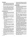
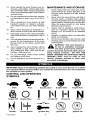
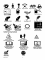
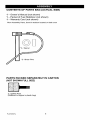
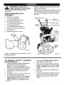

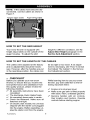
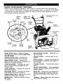
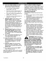
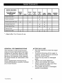
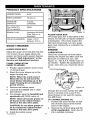

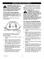
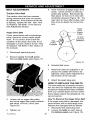
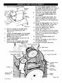
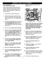
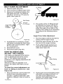
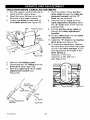
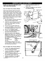


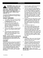

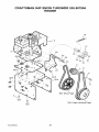
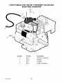


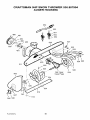

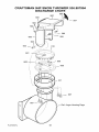
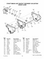

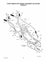

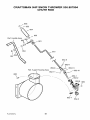
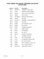
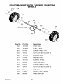
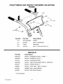
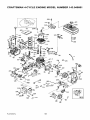

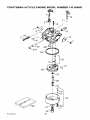
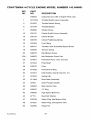
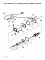


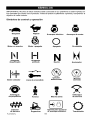
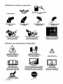
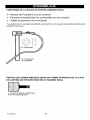
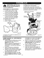
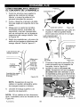
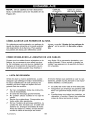
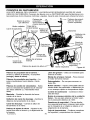
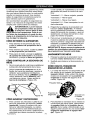
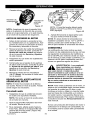

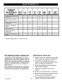

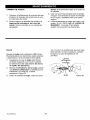
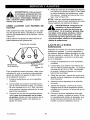
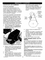
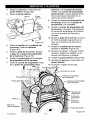
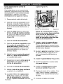
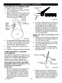
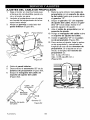
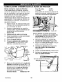
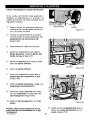
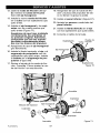

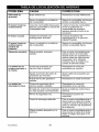


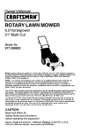
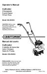
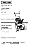
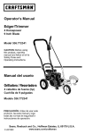

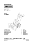
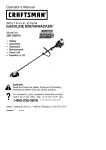
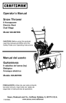


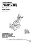
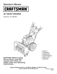
![CRRFTSMRN °] - at snowblowerguide.com](http://vs1.manualzilla.com/store/data/006202620_1-711fb90bb2c79d693479b4ac54c29ad0-150x150.png)