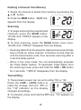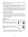
1
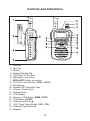
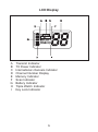
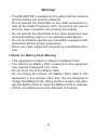
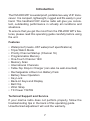
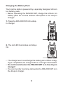
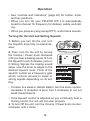
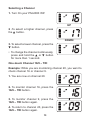
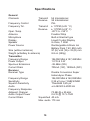
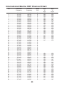
PM-2000 WP
OWNER’S MANUAL
Contents
Controls and Indications ..................................................... 4
LCD Display ........................................................................ 5
Warning! ............................................................................. 6
Lithium Ion Battery Pack Warning ................................. 6
Introduction ......................................................................... 7
Features ........................................................................ 7
Technical Support and Service ..................................... 7
Included in your Package ................................................... 8
Getting Started .................................................................... 9
Mounting the Drop-in Charger ....................................... 9
Attaching the Antenna ................................................... 9
Attaching the Battery Pack .......................................... 10
Attaching the Beltclip ................................................... 10
Charging the Battery Pack ........................................... 11
Operation .......................................................................... 12
Turning On the Unit and Setting Squelch .................... 12
Selecting a Channel .................................................... 13
One-touch Channel 16/9 – TRI ................................... 13
Triple Watch ................................................................ 14
Programming a Channel into Memory ........................ 15
Deleting a Channel from Memory ............................... 15
Scanning ..................................................................... 15
Transmitting ................................................................. 16
Lighted Keys and Display ........................................... 16
Battery Indicator .......................................................... 16
Key Lock ...................................................................... 17
Troubleshooting ................................................................ 17
Warranty ........................................................................... 18
Specifications .................................................................... 19
International Marine VHF Channel Chart .......................... 20
Certificate of conformity .................................................... 21
3
Controls and Indications
1.
2.
3.
4.
5.
6.
7.
8.
9.
10.
11.
12.
13.
14.
15.
16.
17.
18.
19.
Antenna
Belt Clip
Battery
Battery Release Clip
PTT (Push to Talk) Key
UIC Button: non active
WX/ALERT Button: non active
TX Power / Lock Button (1/5W – LOCK)
Microphone
Speaker MIC (Optional) Jack
Volume / Power Knob
Squelch Knob
LCD Display
Memory / FIPS Button (MEM – FIPS)
Scan Button (SCAN)
Channel Up Button ▲
16/9 / Triple Watch Button (16/9 – TRI)
Channel Down Button ▼
Speaker
4
LCD Display
A
B
C
D
E
F
G
H
I
Transmit Indicator
TX Power Indicator
International channels Indicator
Channel Number Display
Memory Indicator
Scan Indicator
Battery Indicator
Triple Watch Indicator
Key Lock Indicator
5
Warning!
• The PM-2000 WP is waterproof only when both the antenna
and the battery are properly attached.
• Do not operate the transmitter of any radio equipment unless all the Radio Frequency (RF) connectors are secure
and any open connectors are properly terminated.
• Do not operate the transmitter of any radio equipment near
electrical blasting caps or in an explosive atmosphere.
• Do not let children operate any transmitter-equipped radio
equipment without proper supervision.
• Have your radio equipment serviced by a qualified technician.
Lithium Ion Battery Pack Warning
• This equipment contains a Lithium Ion Battery Pack.
• The Lithium Ion Battery Pack contained in this equipment
may explode if disposed of in a fire.
• Do not short-circuit the Battery Pack.
• Do not charge the Lithium Ion Battery Pack used in this
equipment in any charger other than the one designed to
charge this Battery Pack. Using another charger may damage the Battery Pack or cause the Battery Pack to explode.
• Lithium Ion batteries must be disposed of properly.
6
Introduction
The PM-2000 WP is a waterproof, portable two-way VHF transceiver. It is compact, lightweight, rugged and fits easily in your
hand. This handheld VHF marine radio will give you consistent, outstanding performance in virtually all conditions and
situations.
To ensure that you get the most from the PM-2000 WP’s features, please read this operating guide carefully before using
the unit.
Features
•
•
•
•
•
•
•
•
•
•
•
•
•
•
•
Waterproof (meets JIS7 waterproof specifications)
Triple Watch Mode
Priority Channel Startup (Channel 16)
Programmable Memory
One-Touch Channel 16/9
Memory Scan
International Channels
Table-Top Drop-In Charger (can also be wall-mounted)
Rechargeable Lithium Ion Battery Pack
Battery Save Operation
Key Lock
Back-Lit Keys and Display
Belt Clip
Wrist Strap
TX Power 1W/5W
Technical Support and Service
If your marine radio does not perform properly, follow the
troubleshooting tips in the back of this operating guide.
Unauthorized adjustment will void the warranty.
7
Included in your Package
PM-2000 WP
DC Adapter
Beltclip
AC Adapter
Drop-in Charger
Wrist Strap
Antenna
Lithium Battery
Mounting Screws
Owner’s Manual
If any of these items are missing from the box, contact your
Dealer.
8
Getting Started
Mounting the Drop-in Charger
1. Mount the drop-in charger to either a counter or wall.
To counter:
Attach the drop-in charger
using the mounting screws
and washers as follows.
To wall:
Insert the two mounting
screws into the wall keeping
the same space as the holes
on the charger.
Place the charger with the
screws through the larger
holes then turn the charger.
2. Plug one end of the AC
adapter into the wall outlet
and the other end
into the drop-in charger.
When you mount the dropin charger on your boat, use
the DC adapter instead.
Attaching the Antenna
Attach the antenna to the
PM-2000 WP.
Be sure the antenna is firmly
seated.
9
Attaching the Battery Pack
1. Place the battery pack onto the
back of the radio. It will only fit in
one way.
2. Snap the battery release clip
until it clicks. Be sure the battery
pack fits tightly against the PM2000 WP’s body.
Attaching the Beltclip
1. Hold the beltclip in the direction as follows.
2. Apply it to the hanger piece on
the back of the radio. Then slid it
up.
3. You will hear a click. The
beltclip is firmly attached.
4. To take the beltclip off the radio, turn it and slid it up.
10
Charging the Battery Pack
Your marine radio is powered by a specially designed Lithium
Ion battery pack.
• Before operating the PM-2000 WP, charge the Lithium Ion
battery pack for 6 hours without interruption in the drop-in
charger.
1. Place the PM-2000 WP in the dropin charger.
2. The red LED illuminates and stays
On.
• The charger won’t overcharge the battery pack. When charging is completed, the charge LED is no longer illuminated.
• Do not transmit when the PM-2000 WP is in the drop-in
charger!
• You can monitor incoming calls while the PM-2000 WP is in
the drop-in charger.
11
Operation
• See “controls and Indicators” (page 40) for button, knob,
and key positions.
• When you turn On your PM-2000 WP, it is automatically
tuned to channel 16, frequency for distress, safety, and calling.
• When you press any key (except PTT), a short tone sounds.
Turning On the Unit and Setting Squelch
1. Before you turn On the unit, turn
the Squelch knob fully counterclockwise.
2. Then, turn On the unit by turning
the Volume / Power knob clockwise
until you hear a hissing sound. 3. Turn
the Squelch knob clockwise, just until Strong Signals the hissing sound
stops. Use the knob to adjust to the
desired squelch level. Think of the
squelch control as a frequency gate
which controls access to weak or
strong signals depending on its setting.
• To listen to a weak or distant station, turn the knob counterclockwise. If reception is poor, turn it clockwise to cut out
weak transmissions.
• If the squelch control is adjusted so you continually hear a
hissing sound, the unit will not scan properly.
4. To turn Off the unit, turn the Volume / Power knob counterclockwise until it clicks.
12
Selecting a Channel
1. Turn On your PM-2000 WP.
UP
2 .To select a higher channel, press
the ▲ button.
DOWN
3. To select a lower channel, press the
▼ button.
• To change the channel continuously,
press and hold the ▲ or ▼ button
for more than 1 second.
One-touch Channel 16/9 – TRI
Example: While you are monitoring channel 20, you want to
check channel 16 or channel 9.
1. You are now on channel 20.
2. To monitor channel 16, press the
16/9 – TRI button.
3. To monitor channel 9, press the
16/9 – TRI button again.
4. To return to channel 20, press the
16/9 – TRI button again.
13
Triple Watch
Triple Watch mode monitors channels 16 and 9 for a signal
while you listen to the currently selected channel. The marine
radio checks channel 16 and 9 for activity every 2 seconds.
1. To select Triple Watch mode, press
and hold the 16/9 – TRI button for 1.5
seconds. A double confirmation tone
sounds.
2. To exit from Triple Watch, press and
hold 16/9 – TRI for 1.5 seconds. A
double confirmation tone sounds.
• While in Triple Watch mode, you
can change the currently selected
channel using the s or t button.
• A momentary press of the 16/9 –
TRI button interrupts Triple Watch
mode and remains on 16, or on
channel 9 if you press once more.
To return to the previous mode, simply press the button again.
Programming a Channel into Memory
Before using the scanning feature, you have to program channels into memory.
1. Select the channel to enter into memory by pressing the ▲
or ▼ button.
2. Press the MEM button to store the
channel. “MEM” appears on the display.
14
Deleting a Channel from Memory
1. Select the channel to delete from memory by pressing the
▲ or ▼ button.
2. Press the MEM button. “MEM” disappears from the display.
Scanning
1. To begin scanning the programmed
channels, press the SCAN button.
“SCAN” and “TRIPLE” appear on the
display.
2. To stop scanning, press the SCAN button once more.
“SCAN” and “TRIPLE” disappear from the display.
• Scanning starts from the lowest to highest channel and stops
when it finds an active channel. It remains on that channel
until the transmission ends, then resumes scanning after a
3 second delay period.
• When in the scan mode, the unit automatically activates
the Triple Watch feature. To deactivate Triple Watch from
the scanning mode, press and hold the 16/9 – TRI button
for 2 seconds. “TRIPLE” disappears from the display.
Transmitting
1. Transmission power can be set to either 5W or 1W.
Press the 1/5W – LOCK button to
make the change, then the “5W” or
the “1W” indicator on the display
changes accordingly.
2. To transmit, press and hold the PTT key. “TX” appears on
the display.
15
3. To return to receive, release the “MEM” key. “TX” disappears from the display.
• If the PTT key is pressed for more than 5 minutes, “TX”
starts blinking and the transmission ends. The TX time out
tone will sound until the PTT key is released.
• If the battery indicator drops to the 1-mark level on the display, when the PTT key is pressed, the radio will not transmit and the “TX” icon starts blinking (refer to the description
of the Battery Indicator).
Lighted Keys and Display
To light the display, press any key excluding the PTT key.
• If you press any button other than the PTT key while the
display and keypad are illuminated, it remains illuminated
for another 5 seconds.
Battery Indicator
When the unit is On, battery power is always indicated on the
display.
When the battery is fully charged, the
battery indicator appears as follows:
When the battery is nearly discharged, the battery indicator appears
as follows:
• When the battery indicator drops to the 1-mark level on the
display, the radio will receive but will not transmit.
16
Key Lock
To prevent accidental entries, you can lock the keypad.
1. Press and hold the 1/5W – LOCK key for 1.5 seconds. The
unit will beep two timesto confirm that the keypad is locked
with “LOCK” indication on the display.
2. To unlock the keypad, press and hold the 1/5W – LOCK
key again for 1.5 seconds. The unit will beep twice to confirm
that the keypad is unlocked, and “LOCK” will disappear.
• You can also unlock the keypad by turning the radio Off and
then On again.
Troubleshooting
• Will not transmit on 5 watt range but will transmit on
the 1 watt range
Cause: Low voltage
ÞRecharge or replace the batteries
• Will not transmit while on the charger
Cause: Low voltage
ÞThe unit is not designed to transmit while on the charger.
The charger does not supply enough power for transmitting
• Battery will not charge
Cause: Charger inoperative
ÞReplace charger. Damage to the charger can be a result
of keying up the radio while on the charger
17
Warranty
This transceiver has a 2 YEARS warranty for materials and
workmanship in its country of purchase against any manufacturing defect recognized by our technical department. It is recommended to read carefully following conditions and to respect them in order not to loose it.
• Any repair under warranty will be free of charge and the
transport costs for sending back will be on charge of our
company.
• A proof of purchase must compulsorily be added to the transceiver in need of repair.
• Don’t install your transceiver without having read this instructions manual.
• Our technical department won’t send nor exchange any
spare parts as part of warranty.
Are not covered
• The battery pack.
• Damages caused by accident , shock , inadequate packing
or the use of accessories that are not in conformity.
• Interventions that modified the conformity features, repairs
or modifications done by third parties which are not agreed
by our company.
• Any opening of the housing cancels the warranty.
18
Specifications
General
Channels
Frequency Control
Frequency Tol.
Transmit
Receive
Transmit
Receive
Oper. Temp.
Antenna
Microphone
Display
Speaker
Power Source
Size (without antenna)
Weight (w/battery & antenna)
Transmitter
Frequency Range
Power Output
Spurious Emissions
Current Drain
Receiver
Receiver Type
Frequency Range
Sensitivity
Squelch Sensitivity
Audio
Frequency Response
Adjacent Channel
Audio Output Power
Current Drain
54 International
55 International
PLL
± 1 PPM (à 25 ° C)
± 1 PPM (à 25° C)
-20°C à + 55°C
Flexible Whip
Built-in Electret type
Liquid Crystal Display
8 ohms, 1 Watt
Rechargeable Lithium Ion
Battery Pack 7.4V 850 mAh
97 (H) x 62 (W) x 33 (D) mm
8.8 oz (250g)
156,050 MHz à 157,425 MHz
1.0 W & 5 W
-38 dBm (5W)
700mA (1W), 1500mA (5W)
Double Conversion Super
Heterodyne Phase
156,300 MHz à 162,025 MHz
0,35 µV pour 12dB SINAD
Threshold 0,25 µV
± 6 dB 500 à 2000 Hz
70 dB @ ± 25 kHz
0.6 W @ 10 % THD
Squelched 40 mA
Max. audio 170 mA
19
International Marine VHF Channel Chart
Chl
Transmitter
Frequency
1 ..................... 156.050
2 ..................... 156.100
3 ..................... 156.150
4 ..................... 156.200
5 ..................... 156.250
6 ..................... 156.300
7 ..................... 156.350
8 ..................... 156.400
9 ..................... 156.450
10 .................... 156.500
11 .................... 156.550
12 .................... 156.600
13 .................... 156.650
14 .................... 156.700
15 .................... 156.750
16 .................... 156.800
17 .................... 156.850
18 .................... 156.900
19 .................... 156.950
20 .................... 157.000
21 .................... 157.050
22 .................... 157.100
23 .................... 157.150
24 .................... 157.200
25 .................... 157.250
26 .................... 157.300
27 .................... 157.350
28 .................... 157.400
60 .................... 156.025
61 .................... 156.075
62 .................... 156.125
63 .................... 156.175
64 .................... 156.225
65 .................... 156.275
66 .................... 156.325
67 .................... 156.375
68 .................... 156.425
69 .................... 156.475
70 .................... RX only
71 .................... 156.575
72 .................... 156.625
73 .................... 156.675
74 .................... 156.725
77 .................... 156.875
78 .................... 156.925
79 .................... 156.975
80 .................... 157.025
81 .................... 157.075
82 .................... 157.125
83 .................... 157.175
84 .................... 157.225
85 .................... 157.275
86 .................... 157.325
87 .................... 157.375
88 .................... 157.425
Receiver
Frequency
Mode
S/D
................ 160.650 ............... D
................ 160.700 ............... D
................ 160.750 ............... D
................ 160.800 ............... D
................ 160.850 ............... D
................ 156.300 ............... S
................ 160.950 ............... D
................ 156.400 ............... S
................ 156.450 ............... S
................ 156.500 ............... S
................ 156.550 ............... S
................ 156.600 ............... S
................ 156.650 ............... S
................ 156.700 ............... S
................ 156.750 ............... S
................ 156.800 ............... S
................ 156.850 ............... S
................ 161.500 ............... D
................ 161.550 ............... D
................ 161.600 ............... D
................ 161.650 ............... D
................ 161.700 ............... D
................ 161.750 ............... D
................ 161.800 ............... D
................ 161.850 ............... D
................ 161.900 ............... D
................ 161.950 ............... D
................ 162.000 ............... D
................ 160.625 ............... D
................ 160.675 ............... D
................ 160.725 ............... D
................ 160.775 ............... D
................ 160.825 ............... D
................ 160.875 ............... D
................ 160.925 ............... D
................ 156.375 ............... S
................ 156.425 ............... S
................ 156.475 ............... S
................ 156.525 ............... S
................ 156.575 ............... S
................ 156.625 ............... S
................ 156.675 ............... S
................ 156.725 ............... S
................ 156.875 ............... S
................ 161.525 ............... D
................ 161.575 ............... D
................ 161.625 ............... D
................ 161.675 ............... D
................ 161.725 ............... D
................ 161.775 ............... D
................ 161.825 ............... D
................ 161.875 ............... D
................ 161.925 ............... D
................ 161.975 ............... D
................ 162.025 ............... D
20
Ship
To
Ship
Ship
To
Shore
.............. YES .............. YES
.............. YES .............. YES
.............. YES .............. YES
.............. YES .............. YES
.............. YES .............. YES
.............. YES ............... NO
.............. YES .............. YES
.............. YES ............... NO
.............. YES .............. YES
.............. YES .............. YES
.............. YES .............. YES
.............. NO ............... YES
.............. YES .............. YES
.............. YES .............. YES
.............. YES .............. YES
.............. YES .............. YES
.............. YES .............. YES
.............. YES .............. YES
.............. NO ............... YES
.............. NO ............... YES
.............. NO ............... YES
.............. NO ............... YES
.............. NO ............... YES
.............. YES .............. YES
.............. YES .............. YES
.............. YES ............... NO
.............. YES .............. YES
.............. YES .............. YES
.............. YES ............... NO
.............. YES .............. YES
.............. YES ............... NO
.............. YES .............. YES
.............. YES .............. YES
.............. YES ............... NO
.............. YES .............. YES
.............. YES .............. YES
.............. YES .............. YES
.............. YES .............. YES
.............. YES .............. YES
.............. YES .............. YES
.............. YES .............. YES
.............. NO ............... YES
.............. NO ............... YES
.............. NO ............... YES
.............. NO ................ NO
CERTIFICATE OF CONFORMITY
We, GROUPE PRESIDENT ELECTRONICS, Route de Sète,
BP 100 – 34540 Balaruc – FRANCE,
Declare, on our own responsibility that the Marine VHF radio-communication transceiver,
Brand: PRESIDENT
Model: PM-2000 WP
Manufactured in China
is in conformity with the essential requirements of the Directive 1999/5/CE (Article 3) adapted to the national law, as well
as with the following European Standards:
EN 60215 / EN 301 178 / EN 60945
Balaruc, the 07/01/2003
Jean-Gilbert MULLER
General Manager
21
22
Siège Social / Head Office France – Route de Sète
BP 100 – 34540 BALARUC
Site internet : http://www.president-electronics.com
E-mail : [email protected]
0341
0497/07-03